
Fatigue Properties of Hot-Dip Galvanized AISI 1020 Normalized Steel in Tension–Compression and Tension–Tension Loading


Abstract
1. Introduction
2. Materials and Methods
2.1. Materials
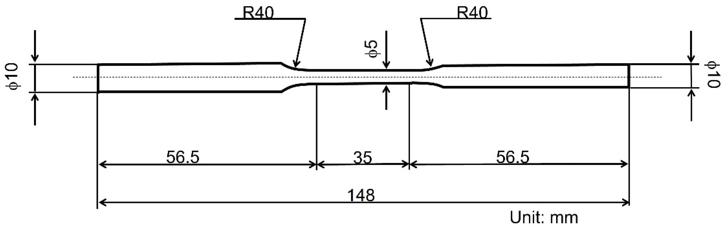
2.2. Methods
3. Results
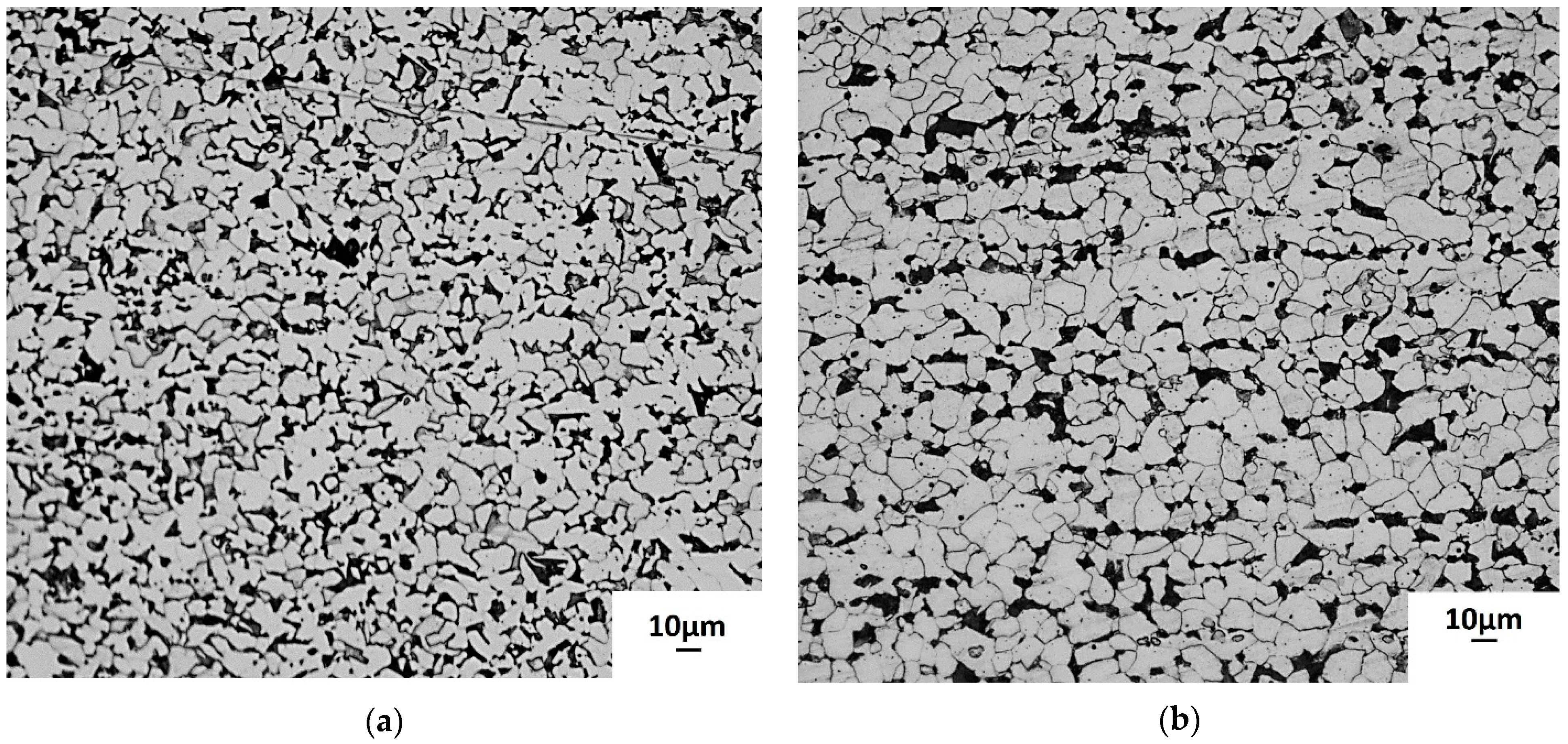
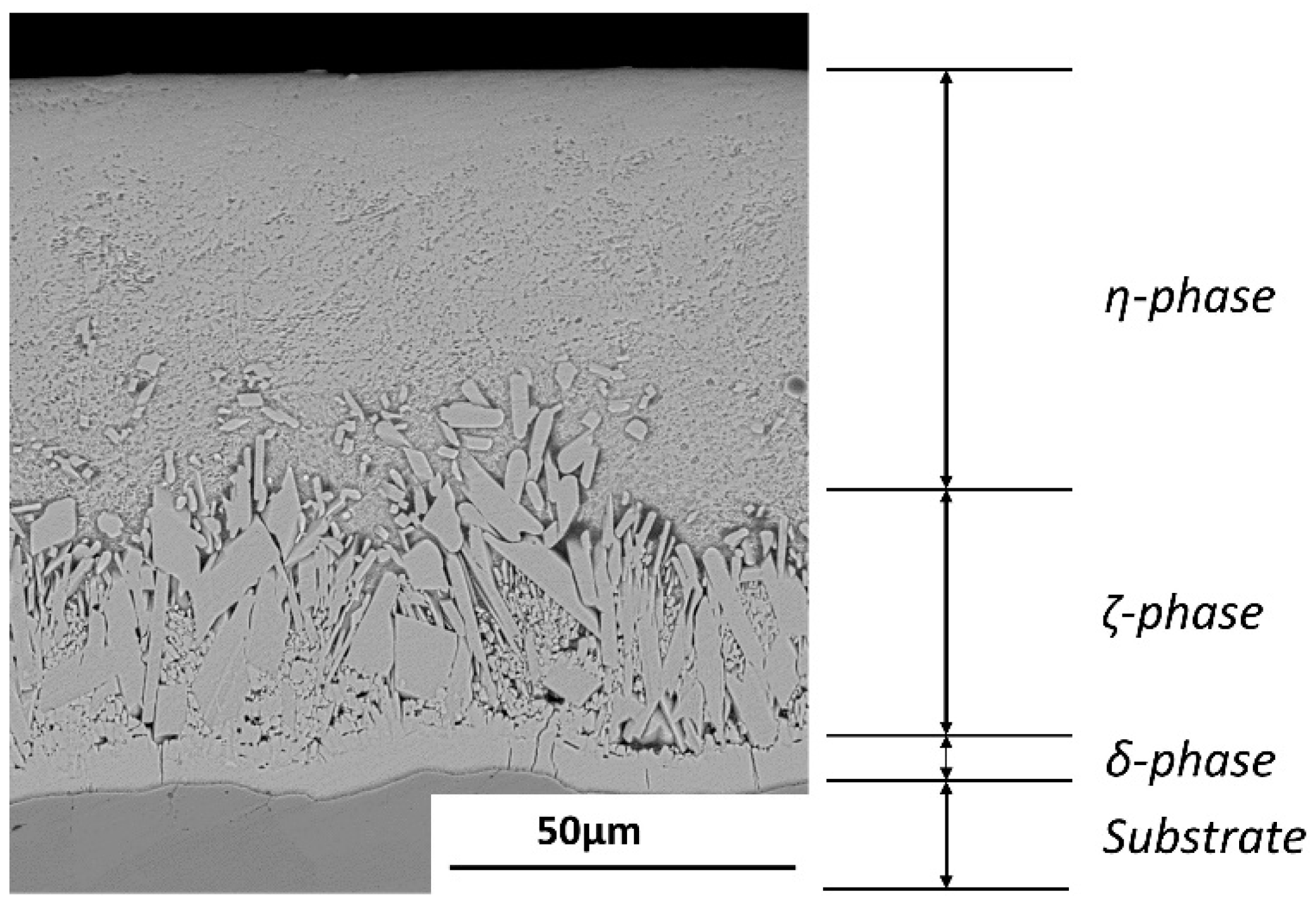
3.1. Microstructural Analysis
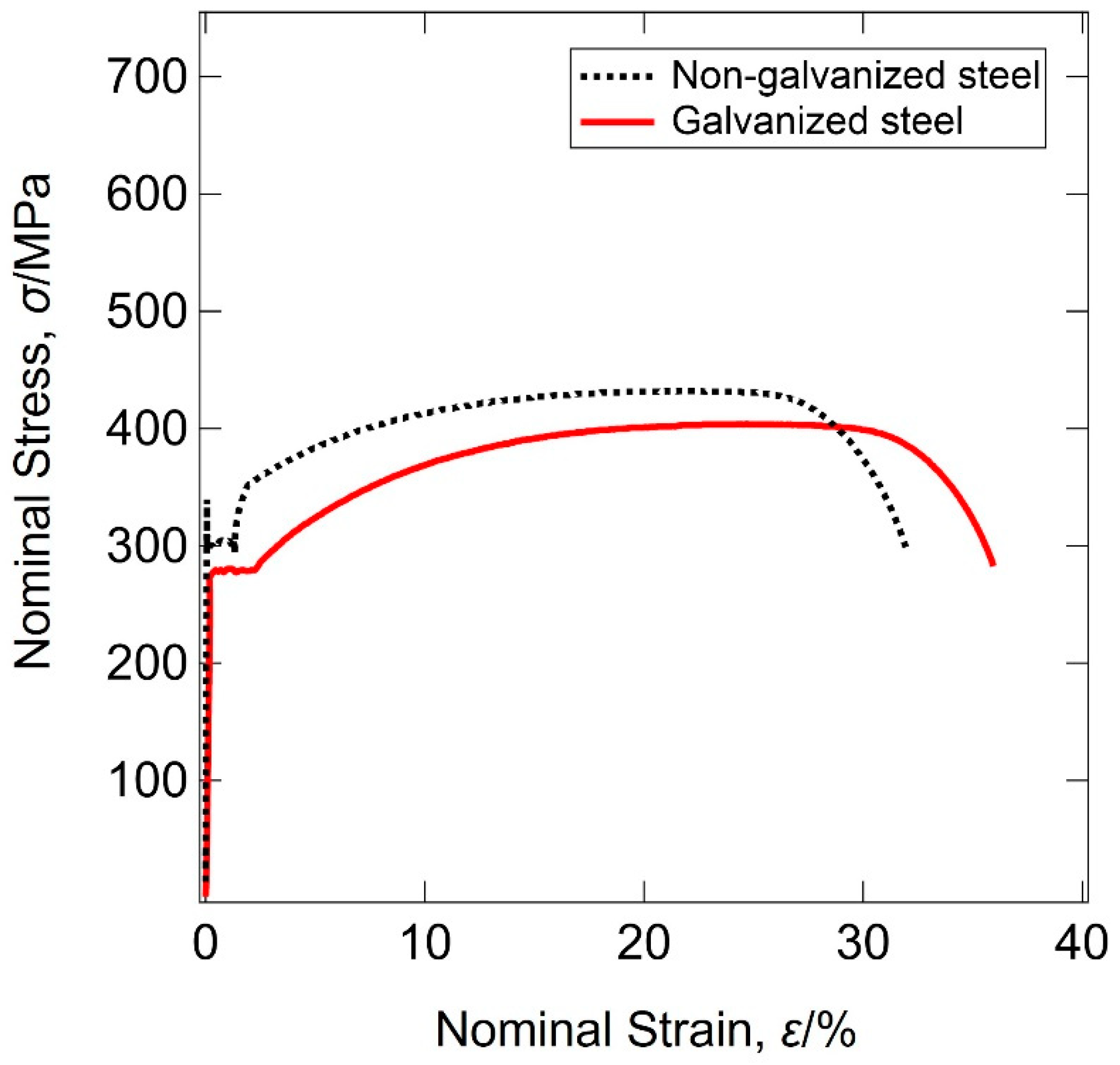
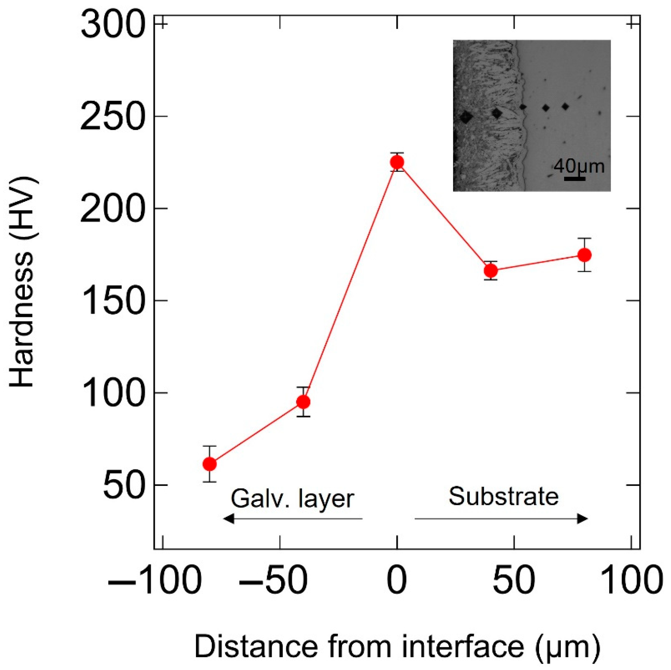
3.2. Mechanical Properties
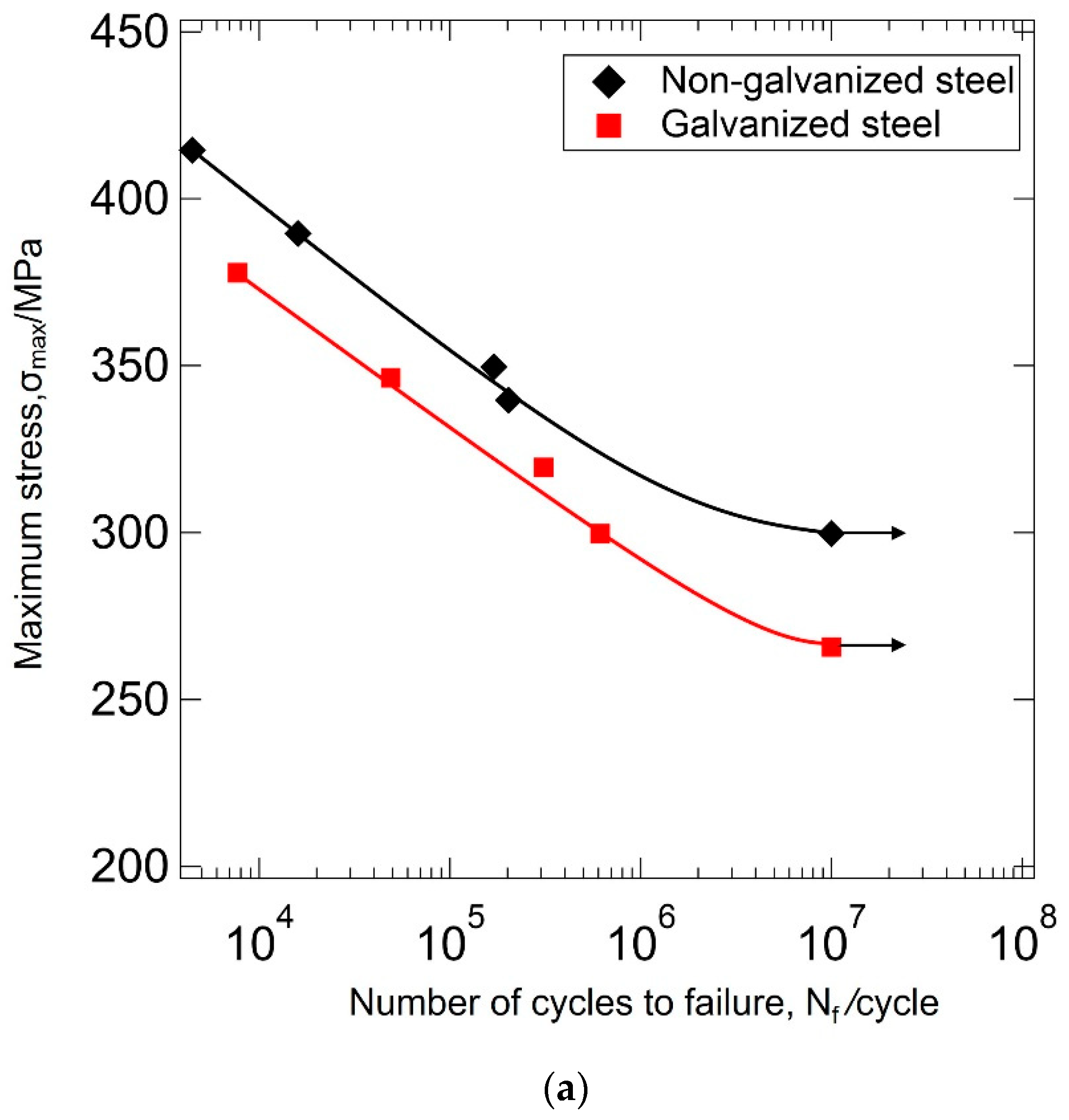
3.3. Fatigue at Different Stress Ratios
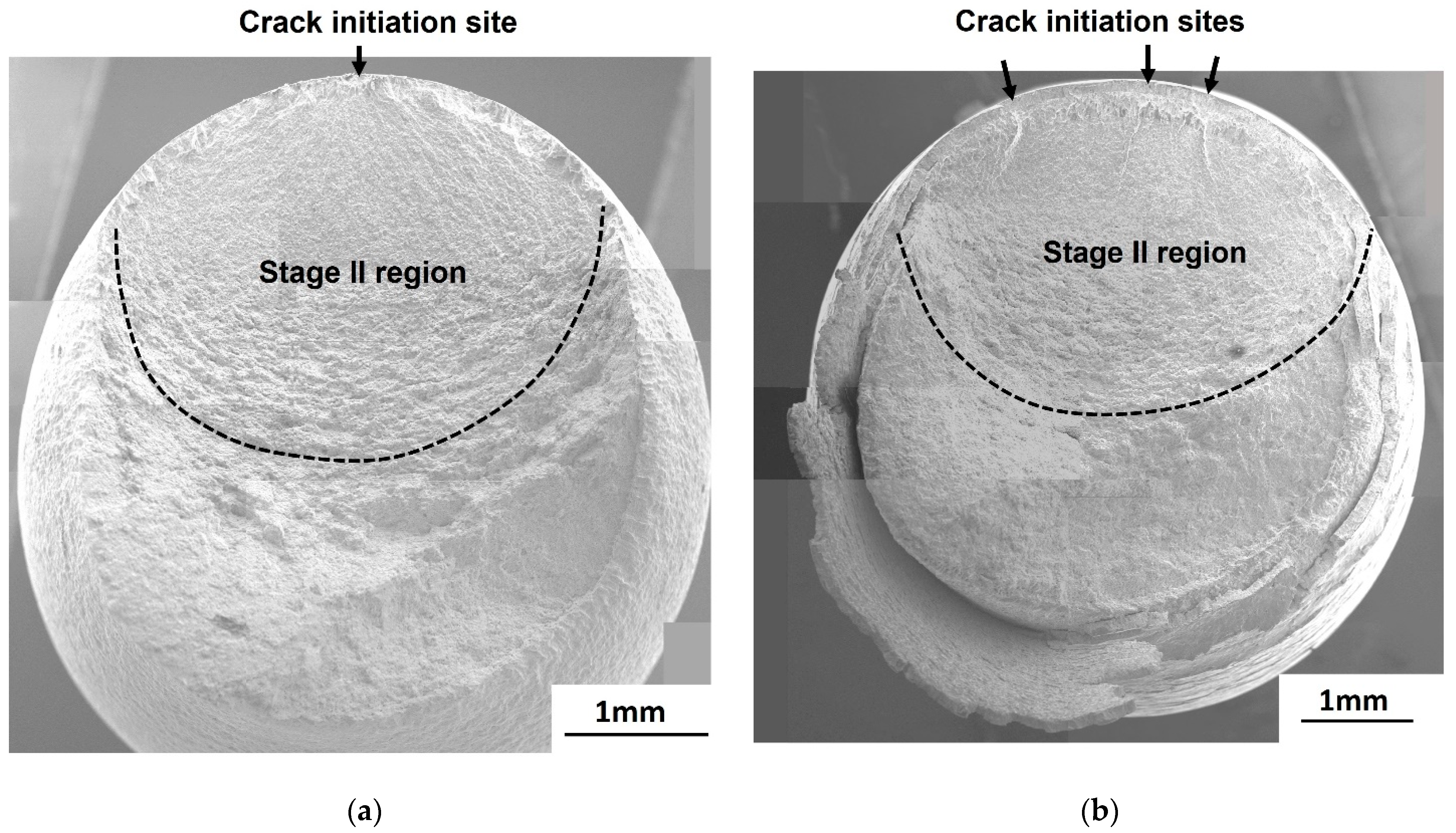
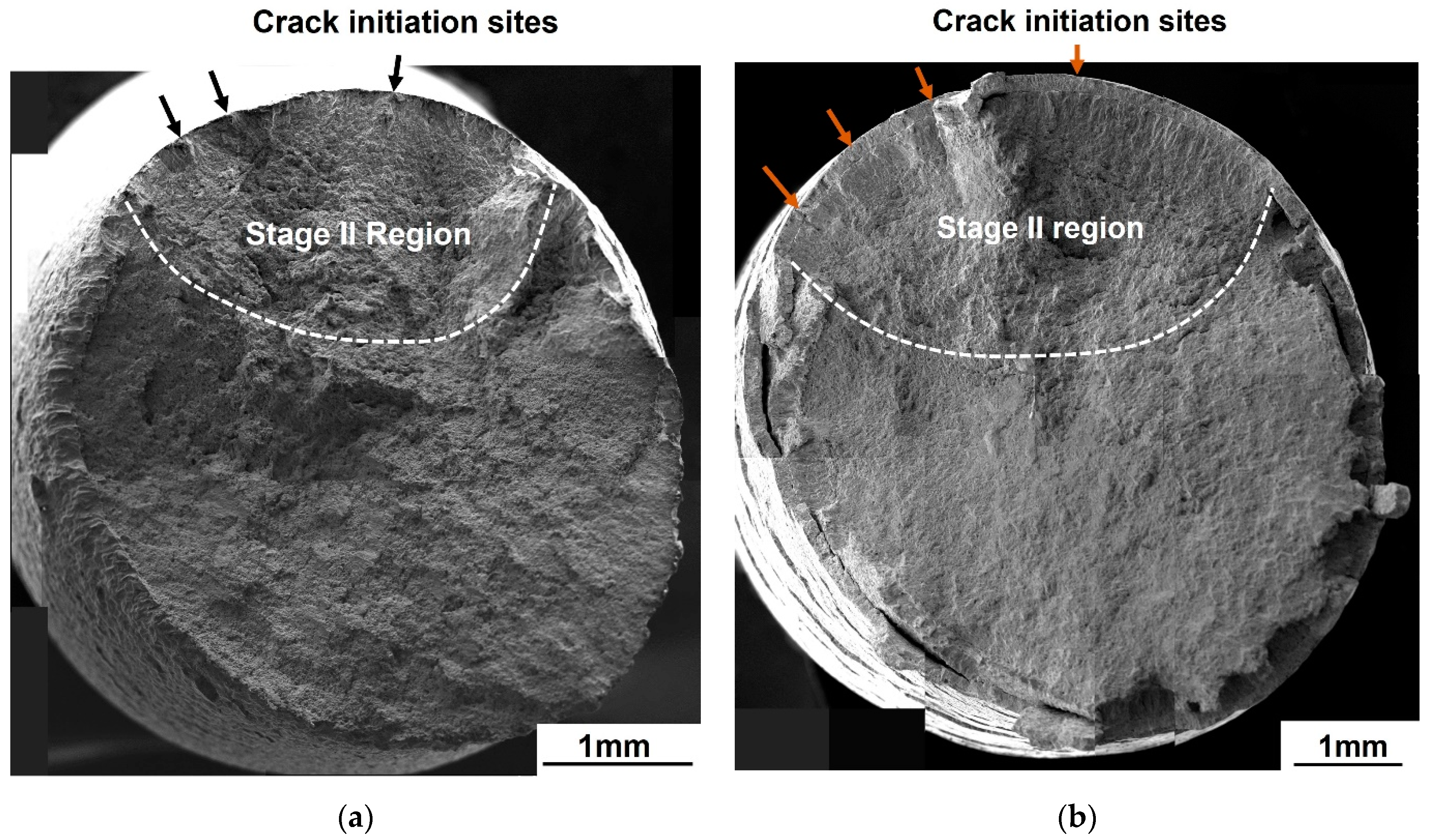
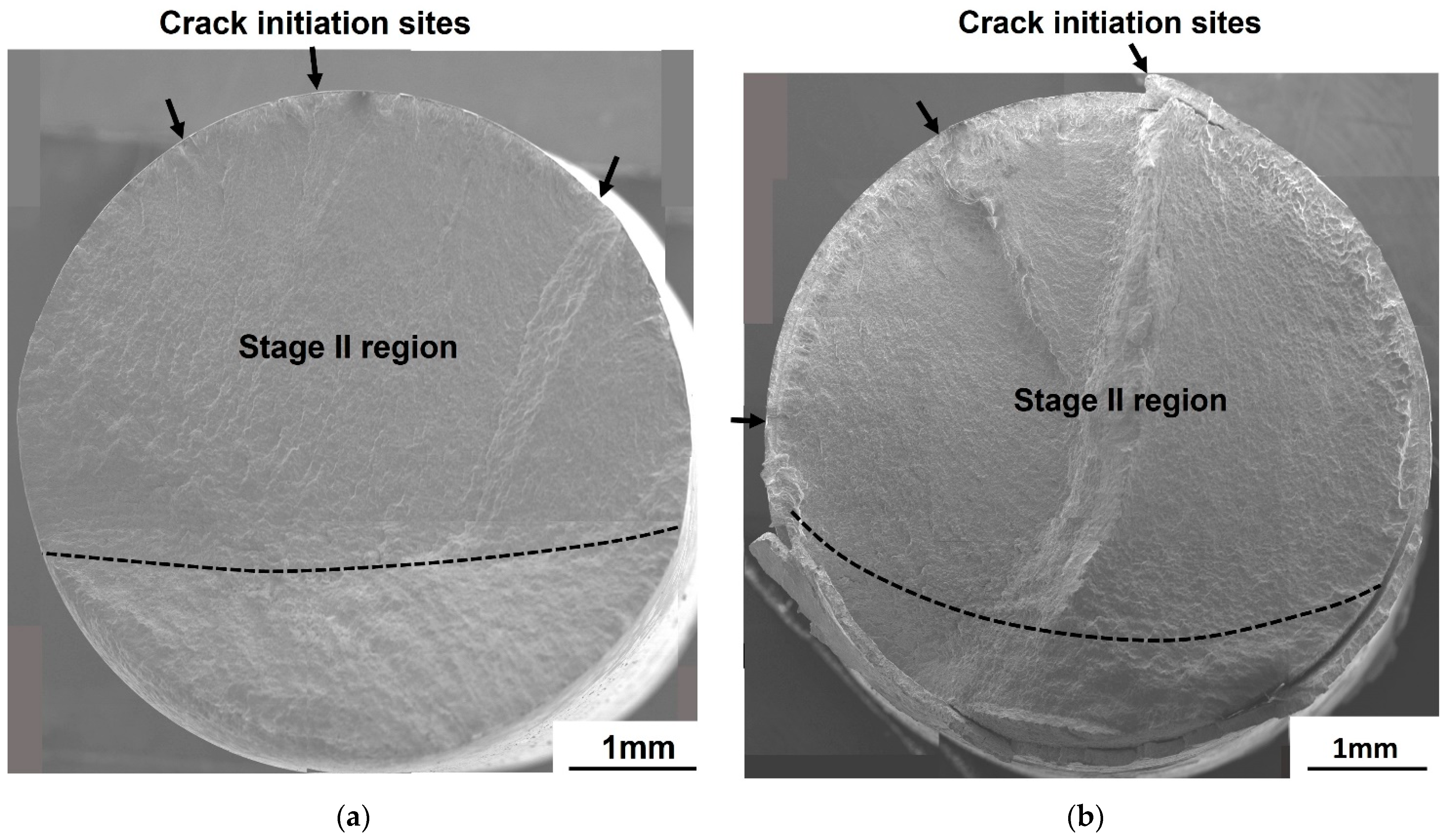
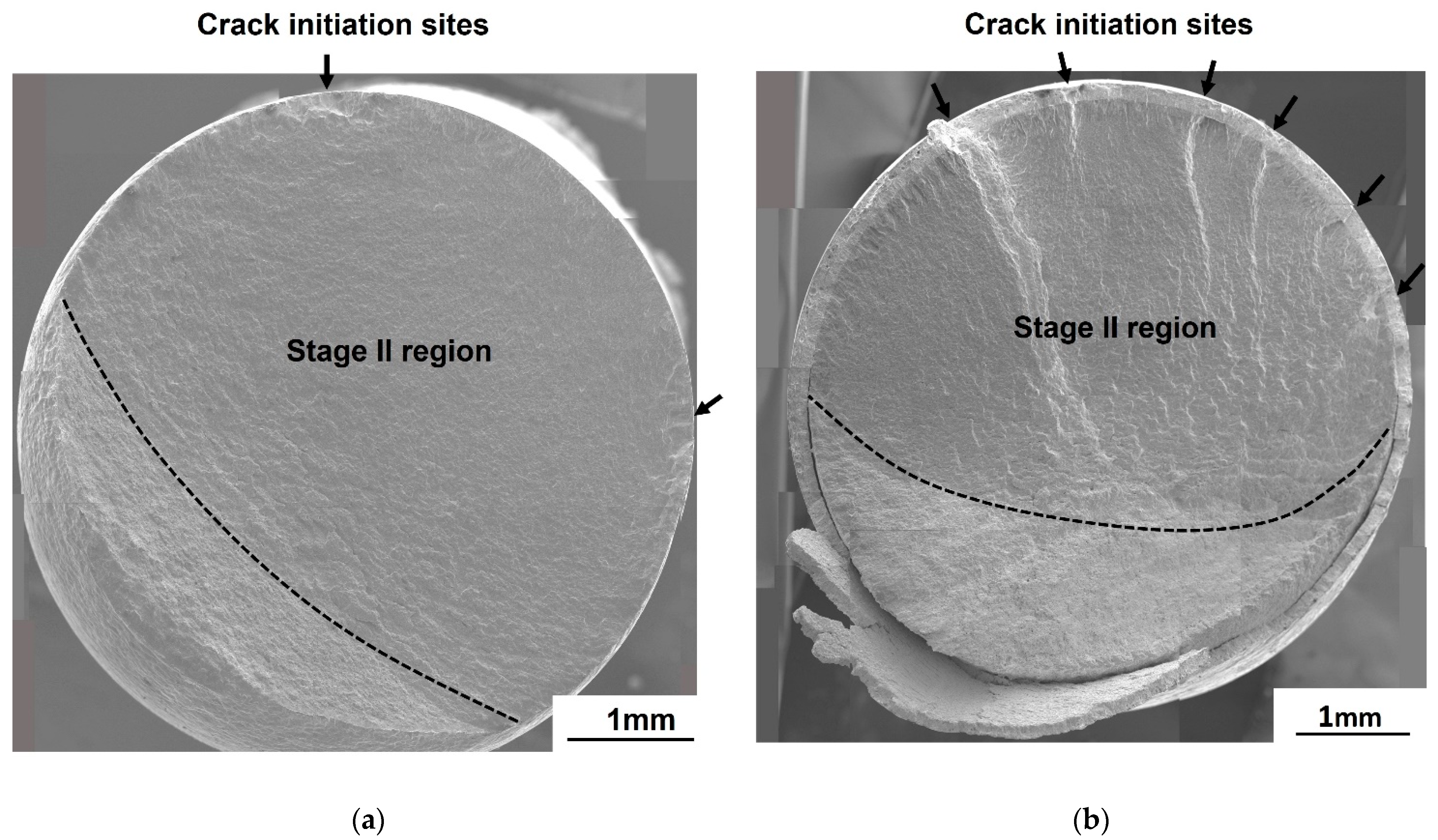
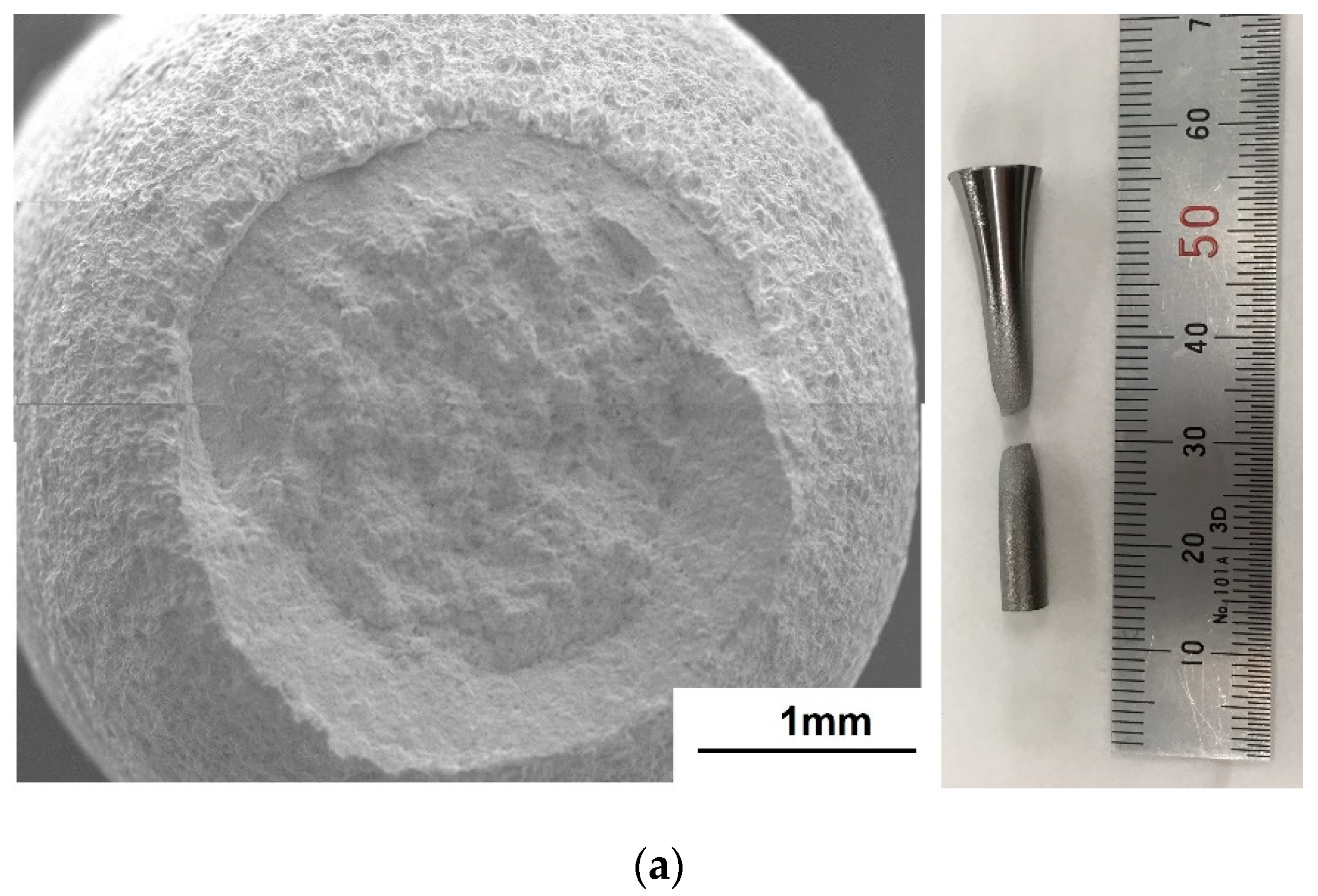
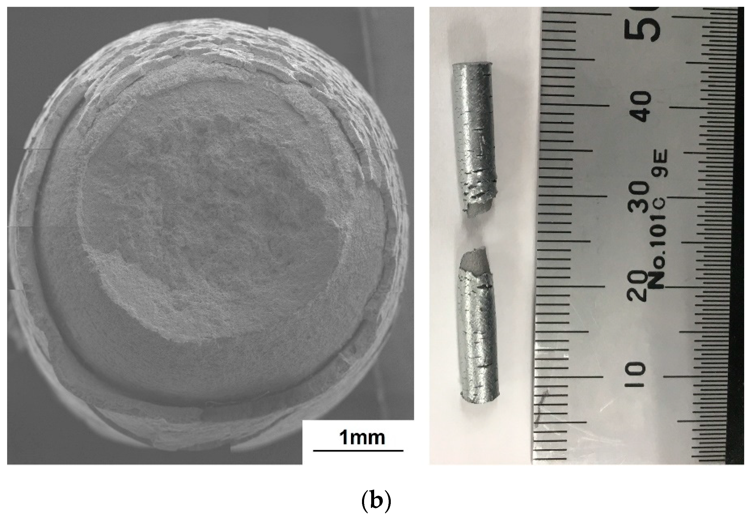
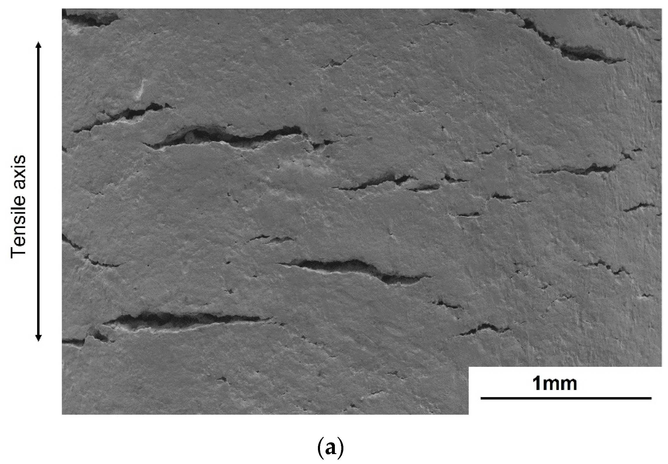
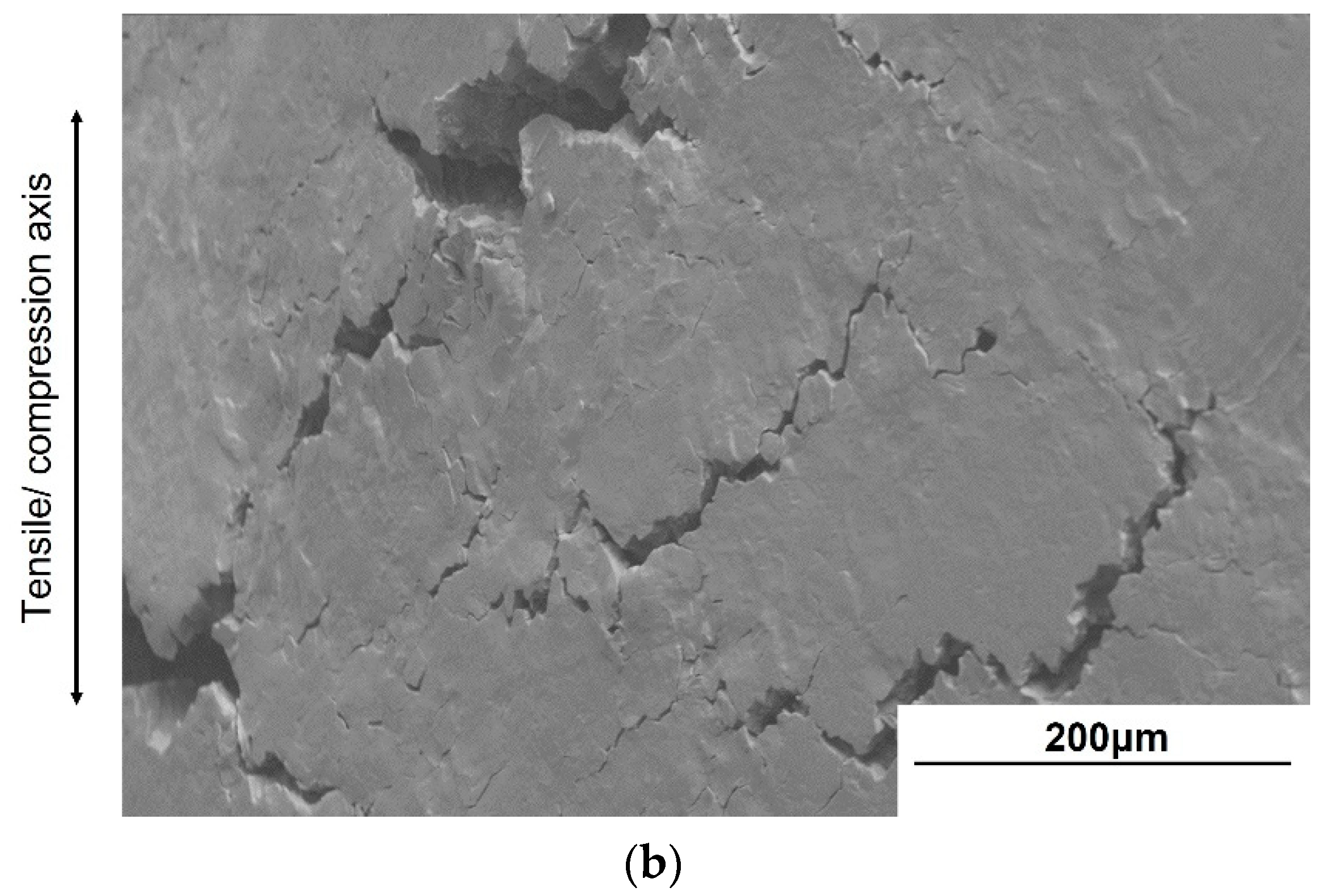
3.4. Fractography at the Different Stress Ratios
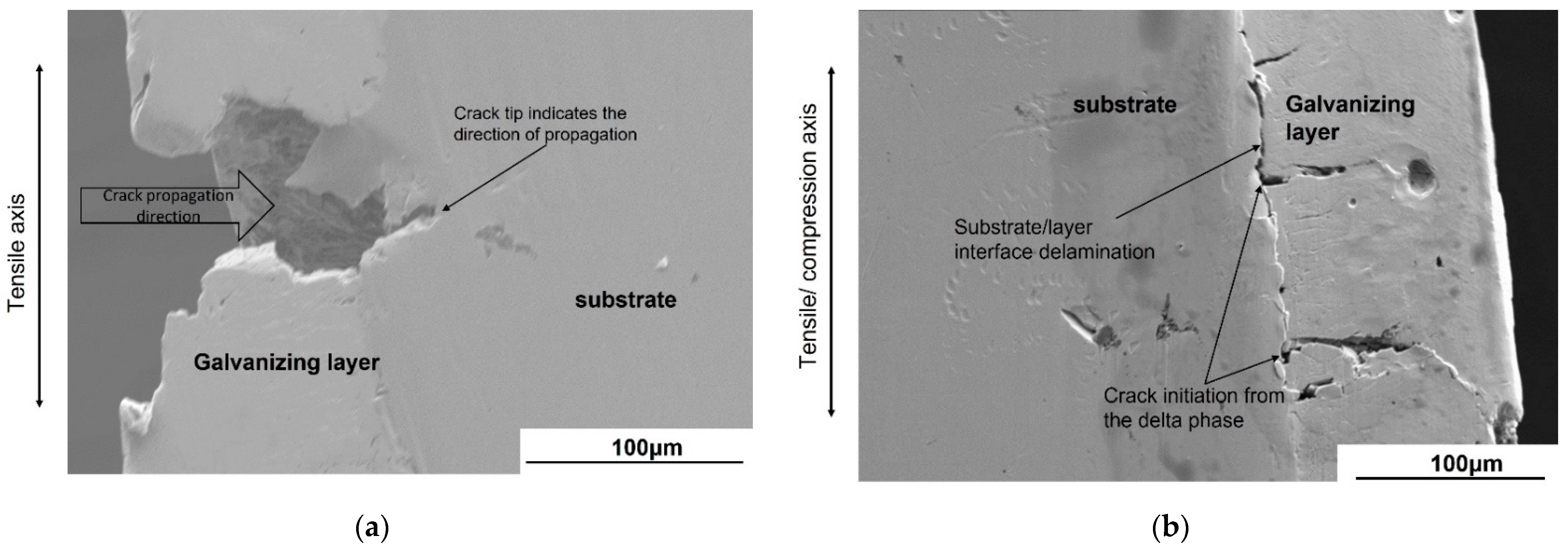
3.5. Crack Initiation and Subcracks
4. Discussion
4.1. Effect of the Plating Layer on the Tensile Properties
4.2. Effect of Cyclic Deformation Mode on the Fatigue Strength of Galvanized Steel
4.3. Effect of Subcracks Initiated from the Galvanizing Layer on the Microcrack Propagation
5. Conclusions
- The reduction in fatigue strength by the galvanizing layer was more pronounced in tension–tension fatigue (R = 0.01 and 0.5). The reduction in fatigue strength was remarkable in the low cycle fatigue at R = 0.5, while it was remarkable in the high cycle fatigue at R = 0.01. The fatigue strength was not significantly affected by the galvanizing layer under tension–compression fatigue (R = −1.0).
- The subcracks in tension–tension fatigue initiated from the eta phase of the galvanizing layer and propagated to substrate. The subcracks in tension–compression fatigue initiated from the delta phase of the galvanizing layer, which is at the layer/substrate interface and propagated to zeta and eta phases. Since the propagation of subcracks from the galvanizing layer to the substrate was only evident in tension–tension fatigue, the fatigue strengths in tension–tension fatigue decreased.
Author Contributions
Funding
Institutional Review Board Statement
Informed Consent Statement
Data Availability Statement
Conflicts of Interest
References
- Ferraz, G.; Rossi, B. On the fatigue behaviour of hot dip galvanized structural steel details. Eng. Fail. Anal. 2020, 118, 104834. [Google Scholar] [CrossRef]
- Kuklík, V. Post on the Issue of Safety of Steel Structures of Hot Dip Galvanized Structural Components. Procedia Eng. 2012, 40, 241–246. [Google Scholar] [CrossRef][Green Version]
- Tayyebi, K.; Sun, M.; Karimi, K. Residual stresses of heat-treated and hot-dip galvanized RHS cold-formed by different methods. J. Constr. Steel Res. 2020, 169, 106071. [Google Scholar] [CrossRef]
- Bellini, C.; Carlino, F.; Natali, S. Analysis of the Al and Ti additions influences on phases generation and damage in a hot dip galvanizing process. Procedia Struct. Integr. 2019, 18, 688–693. [Google Scholar] [CrossRef]
- Bondareva, O.S.; Melnikov, A. Effect of the silicon content in steel on the hot-dip zinc coating microstructure formation. IOP Conf. Ser. Mater. Sci. Eng. 2016, 156, 012015. [Google Scholar] [CrossRef]
- Kania, H.; Mendala, J.; Kozuba, J.; Saternus, M. Development of Bath Chemical Composition for Batch Hot-Dip Galvanizing—A Review. Materials 2020, 13, 4168. [Google Scholar] [CrossRef] [PubMed]
- Katiforis, N.; Papadimitriou, G. Influence of copper, cadmium and tin additions in the galvanizing bath on the structure, thickness and cracking behaviour of the galvanized coatings. Surf. Coat. Technol. 1996, 78, 185–195. [Google Scholar] [CrossRef]
- Pistofidis, N.; Vourlias, G.; Konidaris, S.; Pavlidou, E.; Stergiou, A.; Stergioudis, G. The effect of bismuth on the structure of zinc hot-dip galvanized coatings. Mater. Lett. 2007, 61, 994–997. [Google Scholar] [CrossRef]
- Suliga, M.; Wartacz, R. The influence of the angle of working part of die on the zinc coating thickness and mechanical properties of medium carbon steel wires. Arch. Metall. Mater. 2019, 64, 1295–1299. [Google Scholar] [CrossRef]
- Vogt, J.-B.; Boussac, O.; Foct, J. Prediction of fatigue resistance of a hot-dip galvanized steel. Fatigue Fract. Eng. Mater. Struct. 2001, 24, 33–39. [Google Scholar] [CrossRef]
- Vourlias, G.; Pistofidis, N.; Stergioudis, G.; Tsipas, D. The effect of alloying elements on the crystallization behaviour and on the properties of galvanized coatings. Cryst. Res. Technol. 2004, 39, 23–29. [Google Scholar] [CrossRef]
- Sirin, S.Y. Effect of hot dip galvanizing on the fatigue behavior of hot rolled and ion nitrided AISI 4340 steel. Int. J. Fatigue 2019, 123, 1–9. [Google Scholar] [CrossRef]
- Wood, J.; Alexander, L.; Taylor, I. An experimental and finite element study of the low-cycle fatigue failure of a galvanised steel lighting column. In Proceedings of the NAFEMS World Congress and Exhibition, Crete, Greece, 16–19 June 2009. [Google Scholar]
- Oechsner, M.; Wuttke, U.; Ungermann, D.; Rademacher, D.; Friedrich, S.; Lebelt, S.F.I.P. Galvanizing of highway and railway bridge constructions under dynamic loads. In Proceedings of the EGGA-Assembly, Dresden, Germany, 1 June 2013. [Google Scholar]
- Michailidis, N.; Stergioudi, F.; Maliaris, G.; Tsouknidas, A. Influence of galvanization on the corrosion fatigue performance of high-strength steel. Surf. Coat. Technol. 2014, 259, 456–464. [Google Scholar] [CrossRef]
- Aden-Ali, S.; Chamat, A.; Gilgert, J.; Petit, E.; Dominiak, S.; Schmitt, L.; Gilles, M.; Azari, Z. On the degradation the endurance of silicon-rich TRIP800 steel after hot-dip galvanization. Eng. Fail. Anal. 2009, 16, 2009–2019. [Google Scholar] [CrossRef]
- Carpio, J.; Casado, J.; Álvarez, J.; Gutiérrez-Solana, F. A micromechanical model of the cracking failure on structural steel components during hot-dip galvanizing. Surf. Coat. Technol. 2016, 86, 335–346. [Google Scholar] [CrossRef]
- Eder, M.A.; Haselbach, P.U.; Mishin, O.V. Effects of Coatings on the High-Cycle Fatigue Life of Threaded Steel Samples. J. Mater. Eng. Perform. 2018, 27, 3184–3198. [Google Scholar] [CrossRef]
- Petit, E.; Grosbety, Y.; Aden-Ali, S.; Gilgert, J.; Azari, Z. Microstructure of the coating and mechanical properties of galvanized chromium-rich martensitic steel. Surf. Coat. Technol. 2010, 205, 2404–2411. [Google Scholar] [CrossRef]
- Sun, M.; Packerb, J.A. Hot-dip galvanizing of cold-formed steel hollow sections: A state-of-the-art review. Front. Struct. Civ. Eng. 2019, 13, 49–65. [Google Scholar] [CrossRef]
- Sun, M.; Ma, Z. Effects of heat-treatment and hot-dip galvanizing on mechanical properties of RHS. J. Constr. Steel Res. 2019, 153, 603–617. [Google Scholar] [CrossRef]
- Connor, J.T.; Digges, T.G.; Rosenberg, S.J.; Geil, G.W. Heat Treatment and Properties of Iron and Steel; National Bureau of Standards: Gaithersburg, MD, USA, 1966; pp. 1–48. [Google Scholar]
- Seok, M.-Y.; Choi, I.-C.; Moon, J.; Kim, S.; Ramamurty, U.; Jang, J.-I. Estimation of the Hall–Petch strengthening coefficient of steels through nanoindentation. Scr. Mater. 2014, 87, 49–52. [Google Scholar] [CrossRef]
- Coni, N.; Gipiela, M.L.; D’Oliveira, A.S.C.M.; Marcondes, P.V.P. Study of the mechanical properties of the hot dip galvanized steel and galvalume®. J. Braz. Soc. Mech. Sci. Eng. 2009, 31, 319–326. [Google Scholar] [CrossRef]
- Li, G.; Long, X.Y.; Cui, S.S.; Huang, Q.W.; Chen, Z.P.; Tan, S.H. Influence of zinc coating on anisotropic mechanical properties of hot dip galvanized steel sheet DP600. J. Phys. Conf. Ser. 2018, 1063, 012164. [Google Scholar] [CrossRef]
- Marder, A. The metallurgy of zinc-coated steel. Prog. Mater. Sci. 2000, 45, 191–271. [Google Scholar] [CrossRef]
- Liu, Z.; Li, R.; Jiang, R.; Li, X.; Zhang, M.-X. Effects of Al addition on the structure and mechanical properties of Zn alloys. J. Alloys Compd. 2016, 687, 885–892. [Google Scholar] [CrossRef]
- William, F.H. Fatigue. In Mechanical Behavior of Materials, 2nd ed.; Cambridge University Press: New York, NY, USA, 2010; pp. 275–301. [Google Scholar]
- Sangid, M.D. The physics of fatigue crack initiation. Int. J. Fatigue 2013, 57, 58–72. [Google Scholar] [CrossRef]
- Hasegawa, K.; Morita, M.; Motoda, S. Effect of Microstructure at Coating Layer on Fatigue Strength in Hot-Dip Galvanized Steel. ISIJ Int. 2020, 60, 2525–2532. [Google Scholar] [CrossRef]
- Dimatteo, A.; Lovicu, G.; De Sanctis, R.; Valentini, R.; Aiuto, F.D.; Salvati, M. Influence of galvanizing process on fatigue resistance of microalloyed steels. In Proceedings of the Atti del XXI Convegno Nazionale del Gruppo Italiano Frattura 2011, Cassino, Italy, 13–15 June 2011; pp. 83–91. [Google Scholar]
- Tang, B.; Zhu, B.; Bi, W.; Liu, Y.; Li, J. Effect of Microstructure on the High-Cycle Fatigue Behavior of Ti(43-44)Al4Nb1Mo (TNM) Alloys. Metals 2019, 9, 1043. [Google Scholar] [CrossRef]
- Chan, K.S. Roles of microstructure in fatigue crack initiation. Int. J. Fatigue 2010, 32, 1428–1447. [Google Scholar] [CrossRef]
- Di Cocco, V.; Iacoviello, F.; Natali, S. Damaging micromechanisms in hot-dip galvanizing Zn based coatings. Theor. Appl. Fract. Mech. 2014, 70, 91–98. [Google Scholar] [CrossRef]


| C | Si | Mn | P | S | Cu | Ni | Cr | Fe |
|---|---|---|---|---|---|---|---|---|
| 0.20 | 0.21 | 0.35 | 0.16 | 0.16 | 0.01 | 0.02 | 0.02 | Bal. |
| Microstructure | Ferrite Grain Size (µm) | Pearlite Block Size (µm) | Interlamellar Spacing (µm) |
|---|---|---|---|
| Non-galvanized steel | 11.4 | 5.2 | 0.4 |
| Galvanized steel | 12.6 | 6.1 | 0.4 |
Publisher’s Note: MDPI stays neutral with regard to jurisdictional claims in published maps and institutional affiliations. |
© 2021 by the authors. Licensee MDPI, Basel, Switzerland. This article is an open access article distributed under the terms and conditions of the Creative Commons Attribution (CC BY) license (https://creativecommons.org/licenses/by/4.0/).
Share and Cite
Alweendo, S.T.; Morita, M.; Hasegawa, K.; Motoda, S. Fatigue Properties of Hot-Dip Galvanized AISI 1020 Normalized Steel in Tension–Compression and Tension–Tension Loading. Materials 2021, 14, 7480. https://doi.org/10.3390/ma14237480
Alweendo ST, Morita M, Hasegawa K, Motoda S. Fatigue Properties of Hot-Dip Galvanized AISI 1020 Normalized Steel in Tension–Compression and Tension–Tension Loading. Materials. 2021; 14(23):7480. https://doi.org/10.3390/ma14237480
Chicago/Turabian StyleAlweendo, Shatumbu Thomas, Motoaki Morita, Kayo Hasegawa, and Shinichi Motoda. 2021. "Fatigue Properties of Hot-Dip Galvanized AISI 1020 Normalized Steel in Tension–Compression and Tension–Tension Loading" Materials 14, no. 23: 7480. https://doi.org/10.3390/ma14237480
APA StyleAlweendo, S. T., Morita, M., Hasegawa, K., & Motoda, S. (2021). Fatigue Properties of Hot-Dip Galvanized AISI 1020 Normalized Steel in Tension–Compression and Tension–Tension Loading. Materials, 14(23), 7480. https://doi.org/10.3390/ma14237480