
Robust Heterojunctions of Metallic Alloy and Carbon Fiber-Reinforced Composite Induced by Laser Processing


Abstract
:1. Introduction
2. Materials and Methods
2.1. Preparation of Specimens
2.2. Laser Joining Procedure
2.3. Property Characterization
3. Results and Discussion
4. Conclusions
Author Contributions
Funding
Institutional Review Board Statement
Informed Consent Statement
Data Availability Statement
Acknowledgments
Conflicts of Interest
References
- Cheon, J.; Kim, M. Impact resistance and interlaminar shear strength enhancement of carbon fiber reinforced thermoplastic composites by introducing MWCNT-anchored carbon fiber. Compos. Part B Eng. 2021, 217, 108872. [Google Scholar] [CrossRef]
- Fox, B.; Subic, A. An Industry 4.0 Approach to the 3D Printing of Composite Materials. Engineering 2019, 5, 621–623. [Google Scholar] [CrossRef]
- Hirahara, T.; Hidai, H. Fiber Implantation for Interfacial Joining of Polymer to Metal. ACS Appl. Polym. Mater. 2020, 2, 3049–3053. [Google Scholar] [CrossRef]
- Adham, A.-S.; Prashant, L.; Bardon, J.; Hirchenhahn, P.; Houssiau, L.; Plapper, P. Laser joining of titanium alloy to polyamide: Influence of process parameters on the joint strength and quality. Int. J. Adv. Manuf. Technol. 2020, 107, 2917–2925. [Google Scholar]
- Sun, H.; Kosukegawa, H.; Takagi, T.; Uchimoto, T.; Hashimotoa, M.; Takeshita, N. Electromagnetic pulse-induced acoustic testing and the pulsed guided wave propagation in composite/metal adhesive bonding specimens. Compos. Sci. Technol. 2021, 201, 108499. [Google Scholar] [CrossRef]
- Pang, V.; Thompson, Z.J.; Joly, G.D.; Bates, F.S.; Francis, L.F. Adhesion Strength of Block Copolymer Toughened Epoxy on Aluminum. ACS Appl. Polym. Mater. 2020, 2, 464–474. [Google Scholar] [CrossRef]
- Zhao, T.; Rans, C.; Villegas, I.F.; Benedictus, R. On sequential ultrasonic spot welding as an alternative to mechanical fastening in thermoplastic composite assemblies: A study on single-column multi-row single-lap shear joints. Compos. Part A Appl. Sci. Manuf. 2019, 120, 1–11. [Google Scholar] [CrossRef]
- Lambiase, F.; Ko, D.-C. Feasibility of mechanical clinching for joining aluminum AA6082-T6 and Carbon Fiber Reinforced Polymer sheets. Mater. Des. 2016, 107, 341–352. [Google Scholar] [CrossRef]
- Lambiase, F.; Paoletti, A.; Durante, M. Mechanism of bonding of AA7075 aluminum alloy and CFRP during friction assisted joining. Compos. Struct. 2021, 261, 113593. [Google Scholar] [CrossRef]
- Hirchenhahn, P.; Al Sayyad, A.; Bardon, J.; Felten, A.; Plapper, P.; Houssiau, L. Highlighting Chemical Bonding between Nylon-6.6 and the Native Oxide from an Aluminum Sheet Assembled by Laser Welding. ACS Appl. Polym. Mater. 2020, 2, 2517–2527. [Google Scholar] [CrossRef]
- Arkhurst, B.M.; Seol, J.B.; Lee, Y.S.; Lee, M.; Kim, J.H. Interfacial structure and bonding mechanism of AZ31/carbon-fiber-reinforced plastic composites fabricated by thermal laser joining. Compos. Part B Eng. 2019, 167, 71–78. [Google Scholar] [CrossRef]
- Wu, L.H.; Xiao, B.L.; Nagatsuka, K.; Nakata, K.; Ma, Z.Y. Achieving strong friction lap joints of carbon-fiber reinforced plastic and metals by modifying metal surface structure via laser-processing pretreatment. Compos. Struct. 2020, 242, 112167. [Google Scholar] [CrossRef]
- Nagatsuka, K.; Yoshida, S.; Tsuchiya, A.; Nakata, K. Direct joining of carbon-fiber–reinforced plastic to an aluminum alloy using friction lap joining. Compos. Part B Eng. 2015, 73, 82–88. [Google Scholar] [CrossRef]
- Automated Joining of Hybrid Metal-Thermoplastic Composite Structures. Available online: https://www.compositesworld.com/articles/automated-joining-of-hybrid-metal-thermoplastic-composite-structures (accessed on 24 November 2021).
- Jiao, J.; Zou, Q.; Ye, Y.; Xu, Z.; Sheng, L. Carbon fiber reinforced thermoplastic composites and TC4 alloy laser assisted joining with the metal surface laser plastic-covered method. Compos. Part B Eng. 2021, 213, 108738. [Google Scholar] [CrossRef]
- Tan, X.; Zhang, J.; Shan, J.; Yang, S.; Ren, J. Characteristics and formation mechanism of porosities in CFRP during laser joining of CFRP and steel. Compos. Part B Eng. 2015, 70, 35–43. [Google Scholar] [CrossRef]
- Chen, Y.J.; Yue, T.M.; Guo, Z.N. Laser joining of metals to plastics with ultrasonic vibration. J. Mater. Process. Technol. 2017, 249, 441–451. [Google Scholar] [CrossRef]
- Gao, X.; Huang, Z.; Zhou, H.; Li, D.; Li, Y.; Wang, Y. Higher Mechanical Performances of CF/PEEK Composite Laminates via Reducing Interlayer Porosity Based on the Affinity of Functional s-PEEK. Polym. Compos. 2019, 40, 3749–3757. [Google Scholar] [CrossRef]
- Wu, Z.J.; Romeijn, A.; Wardenier, J. Stress expressions of single-lap adhesive joints of dissimilar adherends. Compos. Struct. 1997, 38, 273–280. [Google Scholar] [CrossRef]
- Elahi, M.A.; Koch, M.; Bardon, J.; Addiego, F.; Plapper, P. Failure mechanism analysis based on laser-based surface treatments for aluminum-polyamide laser joining. J. Mater. Process. Technol. 2021, 298, 117318. [Google Scholar] [CrossRef]
- Zhang, M.Q.; Lu, Z.P.; Friedrich, K. Thermal analysis of the wear debris of polyetheretherketone. Tribol. Int. 1997, 30, 103–111. [Google Scholar] [CrossRef]
- Ramgobin, A.; Fontaine, G.; Bourbigot, S. A Case Study of Polyether Ether Ketone (I): Investigating the Thermal and Fire Behavior of a High-Performance Material. Polymers 2020, 12, 1789. [Google Scholar] [CrossRef]
- Wang, H.; Chen, Y.; Guo, Z.; Guan, Y. Porosity Elimination in Modified Direct Laser Joining of Ti6Al4V and Thermoplastics Composites. Appl. Sci. 2019, 9, 411. [Google Scholar] [CrossRef] [Green Version]
- Demir, K.; Bayramoglu, S.; Akpinar, S. The fracture load analysis of different support patches in adhesively bonded single-lap joints. Theor. Appl. Fract. Mech. 2020, 108, 102653. [Google Scholar] [CrossRef]
- Wang, H.; Feng, W.; Zhang, Z.; Guan, Y.; Zheng, H. Hybrid laser technique for joining of polymer and titanium alloy. J. Laser Appl. 2019, 31, 042017. [Google Scholar] [CrossRef]
- Sun, C.; Jia, P.; Chen, C.; Moradi, A.; Zhou, J.; Al Teneiji, M.; Cantwell, W.J.; Guan, Z.W. The effect of carbon fibre stitching on the tensile behaviour of secondary bonded single- and double-lap composite joints. Compos. Struct. 2021, 265, 113774. [Google Scholar] [CrossRef]
- Amend, P.; Pfindel, S.; Schmidt, M. Thermal joining of thermoplastic metal hybrids by means of mono- and polychromatic radiation. Phys. Procedia 2013, 41, 98–105. [Google Scholar] [CrossRef] [Green Version]


| Laser Power | Pulse Duration | Frequency | Scanning Speed | Beam Diameter |
|---|---|---|---|---|
| 15 W | 209 fs | 100 kHz | 500 mm/s | ~35 μm |
| Laser Type | Laser Power | Wavelength | Scanning Speed | Beam Diameter | Focal Length |
|---|---|---|---|---|---|
| Continuous fiber laser | 200 W | 1030 nm | 2000 mm/s | ~30 μm | 374 mm |
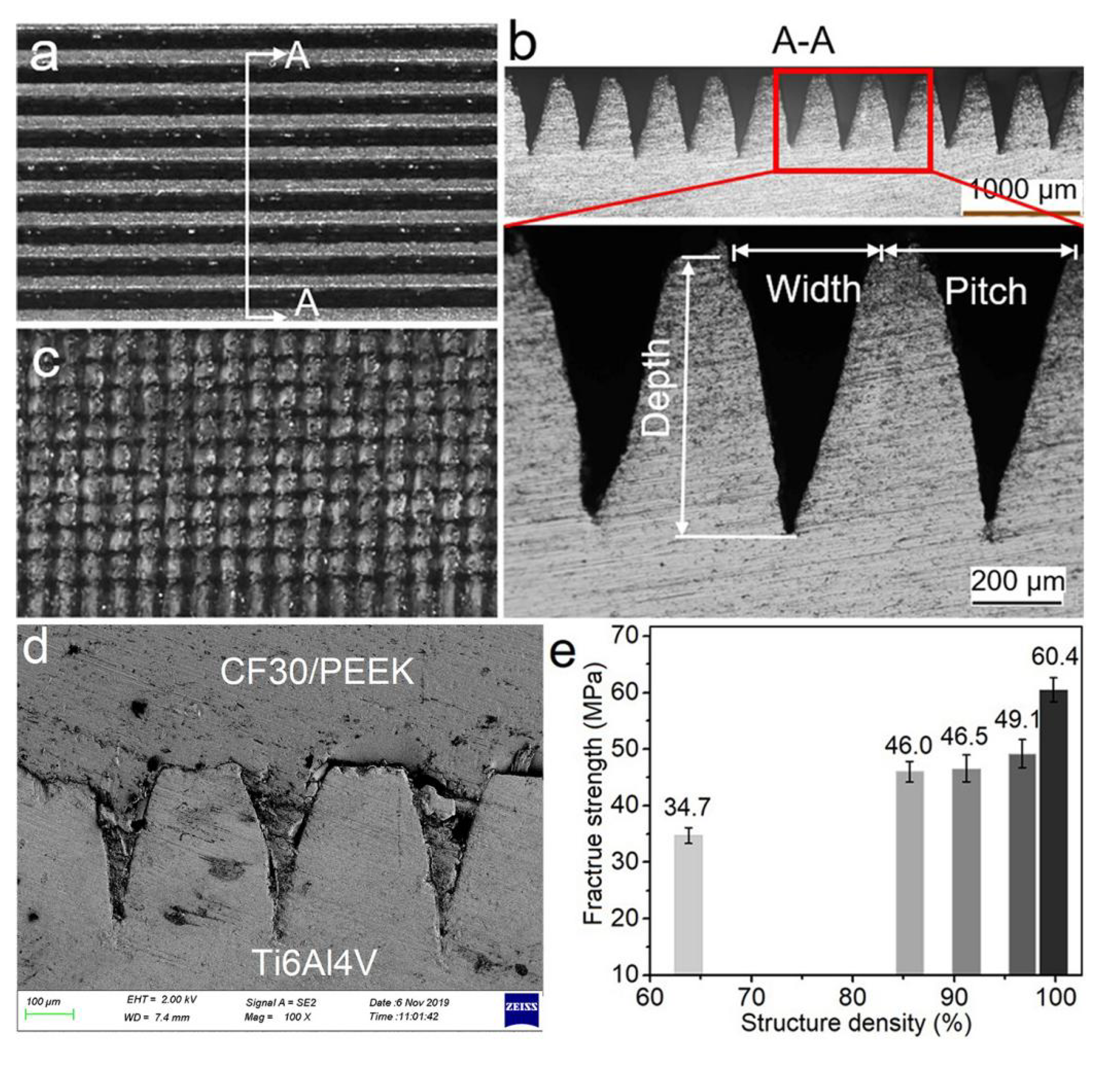
| Case | Microgroove Width (wg), μm | Pitch, μm | Texture | Structure Density, % |
|---|---|---|---|---|
| 1 | 225 | 350 | Groove | 63.8 |
| 2 | 225 | 350 | Pillar | 85.6 |
| 3 | 255 | 350 | Pillar | 91.2 |
| 4 | 290 | 300 | Groove | 96.7 |
| 5 | 290 | 300 | Pillar | 99.8 |
Publisher’s Note: MDPI stays neutral with regard to jurisdictional claims in published maps and institutional affiliations. |
© 2021 by the authors. Licensee MDPI, Basel, Switzerland. This article is an open access article distributed under the terms and conditions of the Creative Commons Attribution (CC BY) license (https://creativecommons.org/licenses/by/4.0/).
Share and Cite
Wang, H.; Yan, P.; Guan, Y. Robust Heterojunctions of Metallic Alloy and Carbon Fiber-Reinforced Composite Induced by Laser Processing. Materials 2021, 14, 7469. https://doi.org/10.3390/ma14237469
Wang H, Yan P, Guan Y. Robust Heterojunctions of Metallic Alloy and Carbon Fiber-Reinforced Composite Induced by Laser Processing. Materials. 2021; 14(23):7469. https://doi.org/10.3390/ma14237469
Chicago/Turabian StyleWang, Haipeng, Peng Yan, and Yingchun Guan. 2021. "Robust Heterojunctions of Metallic Alloy and Carbon Fiber-Reinforced Composite Induced by Laser Processing" Materials 14, no. 23: 7469. https://doi.org/10.3390/ma14237469
APA StyleWang, H., Yan, P., & Guan, Y. (2021). Robust Heterojunctions of Metallic Alloy and Carbon Fiber-Reinforced Composite Induced by Laser Processing. Materials, 14(23), 7469. https://doi.org/10.3390/ma14237469