
Numerical and Experimental Research on the Brushing Aluminium Alloy Mechanism Using an Abrasive Filament Brush

Abstract
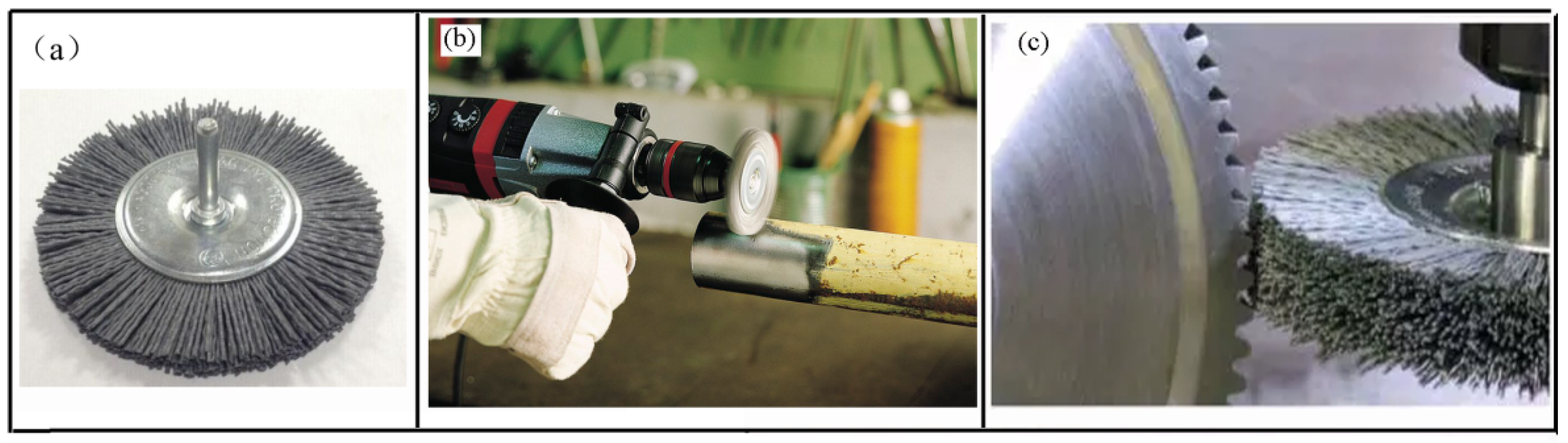
:1. Introduction
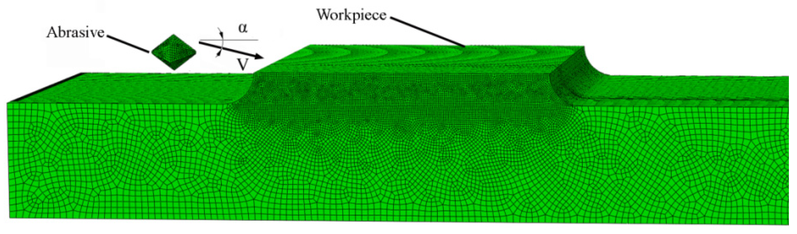
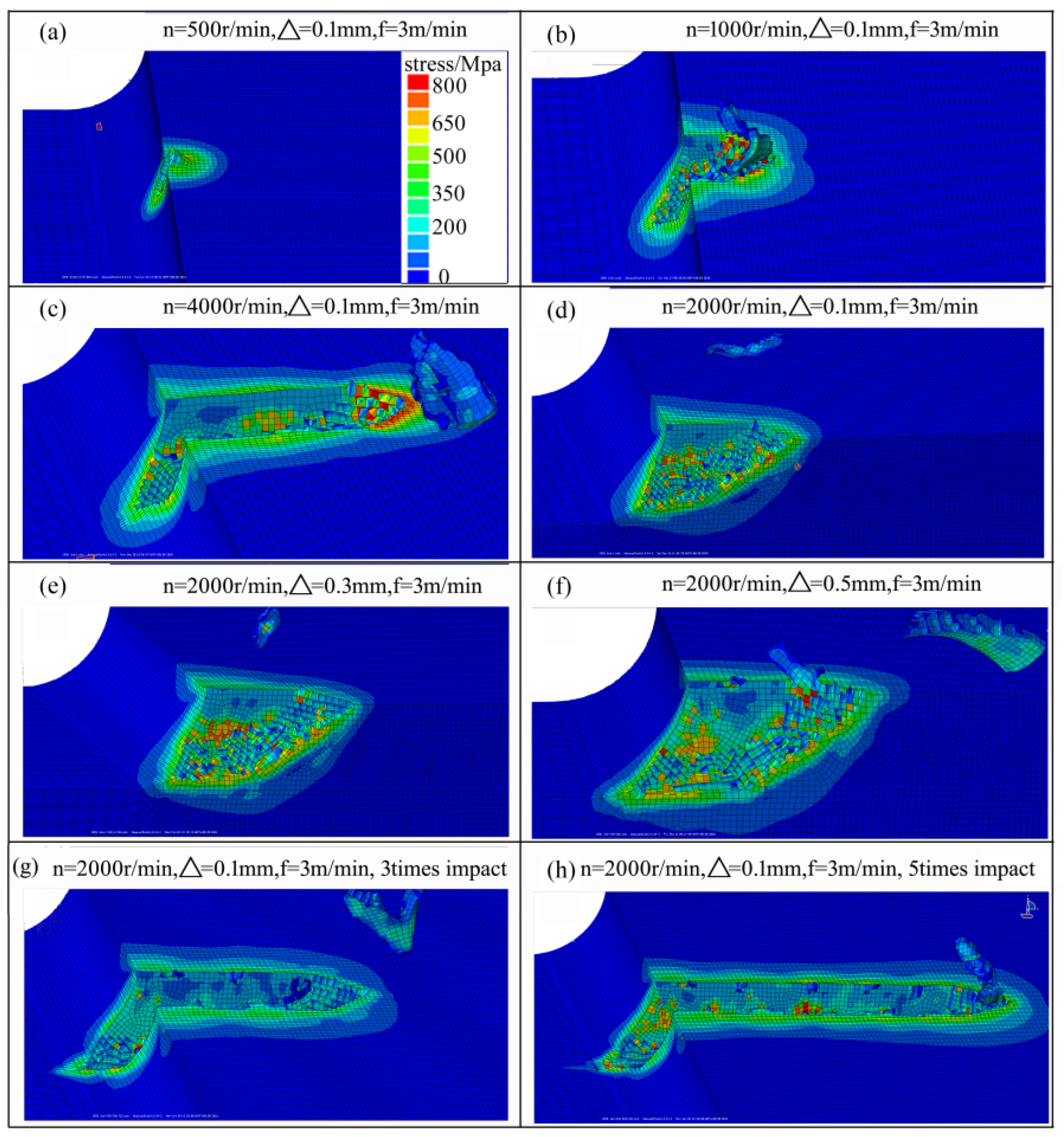
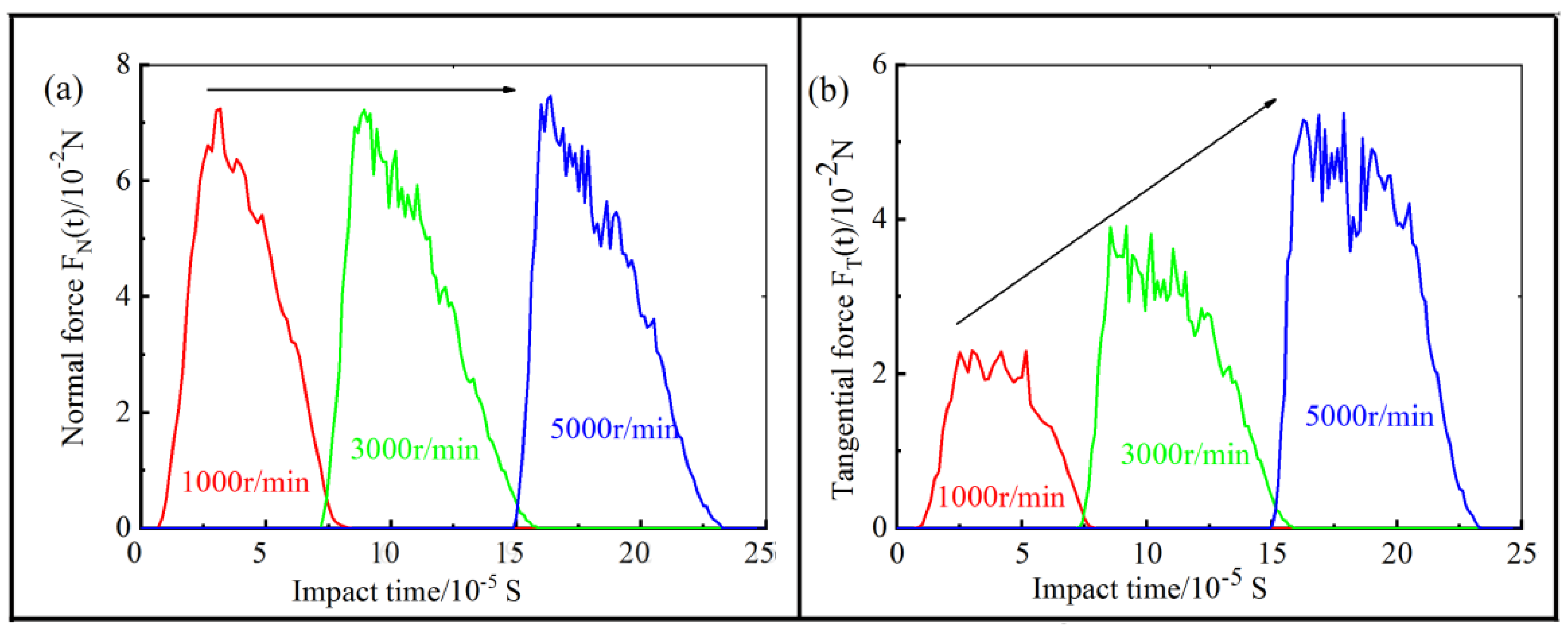
2. Analysis of the Impact Phase
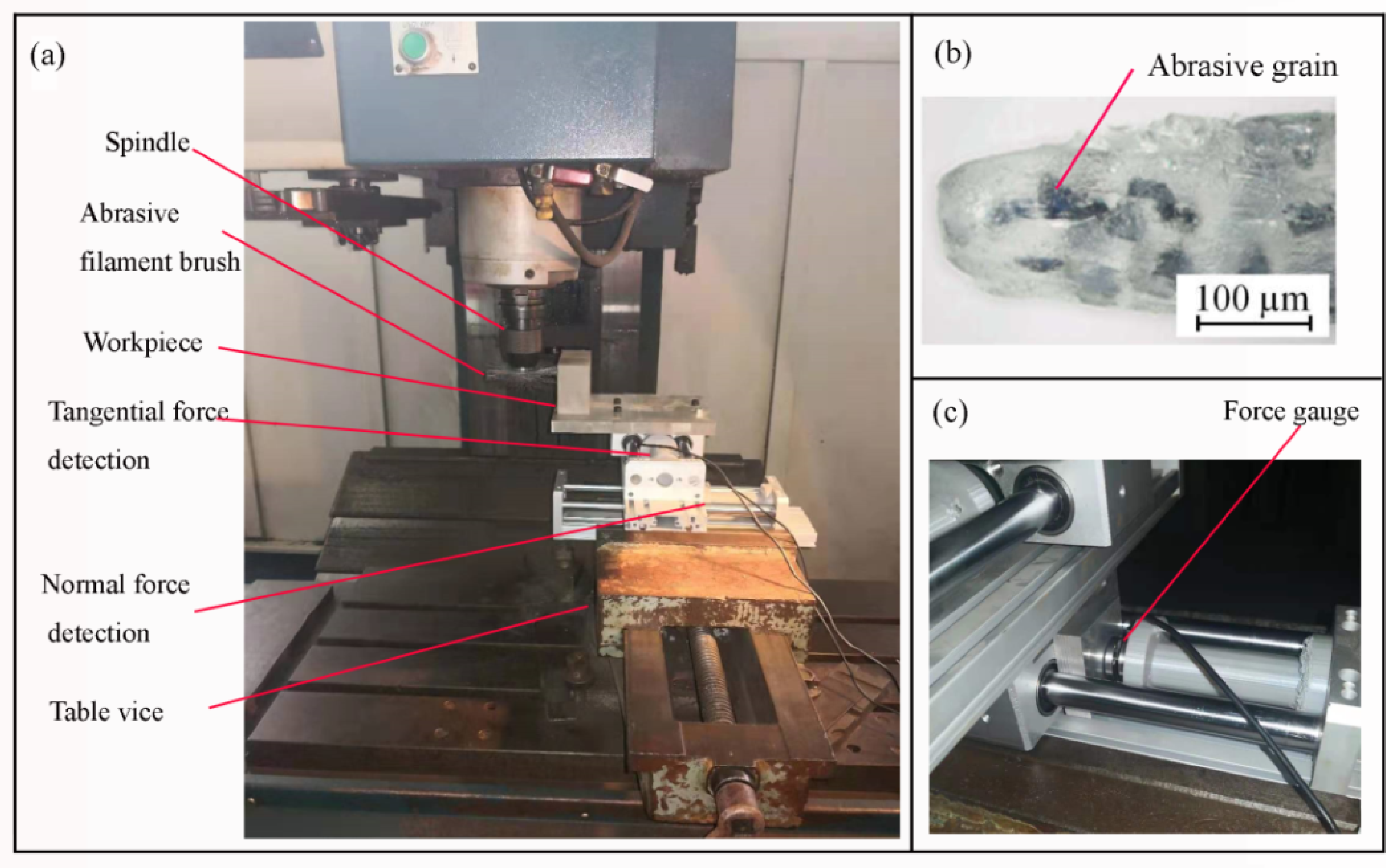
3. Experimental Setup
4. Results
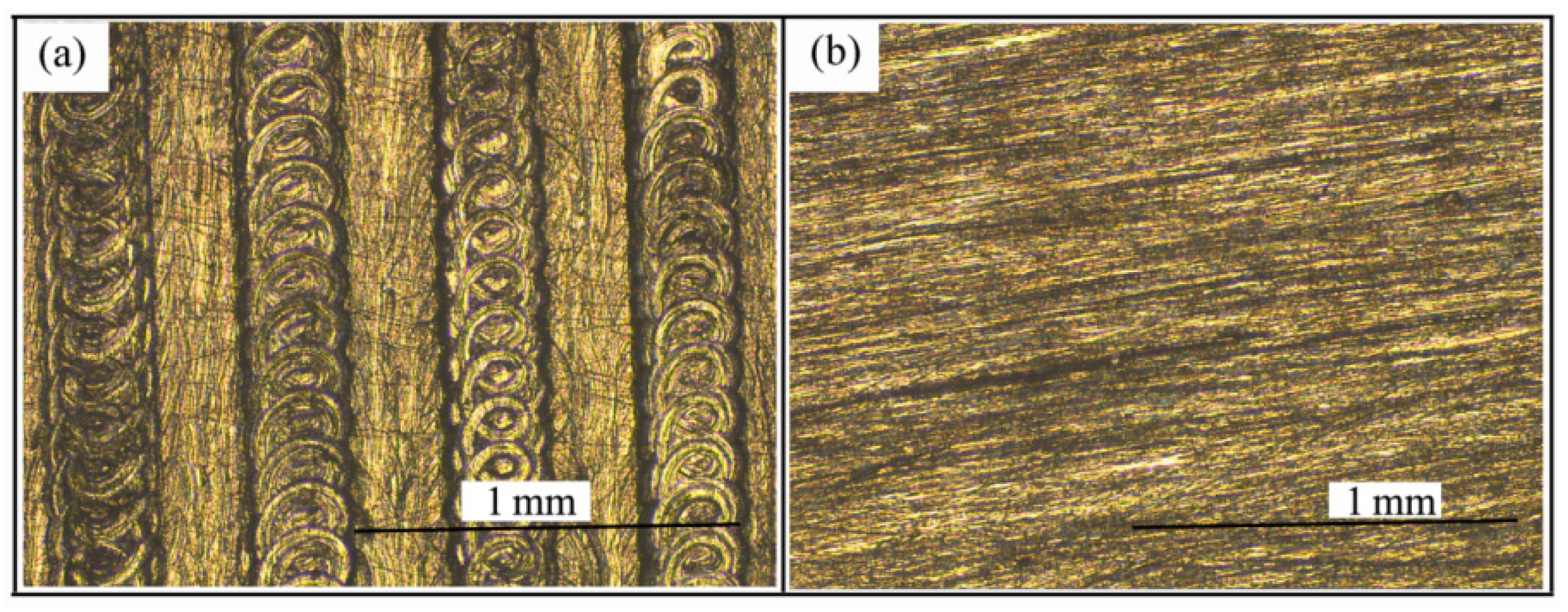
4.1. Surface Topography after Brush Grinding Experiment
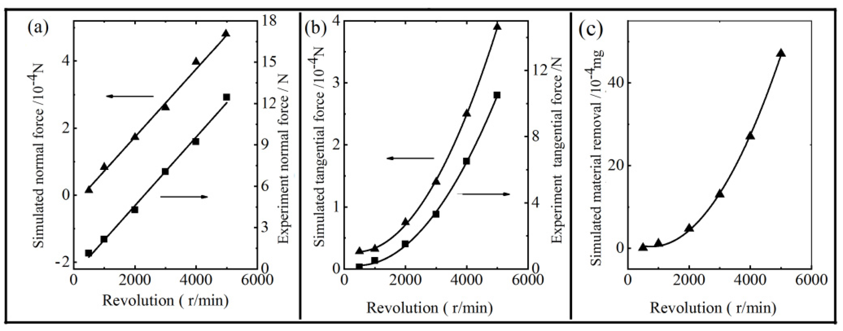
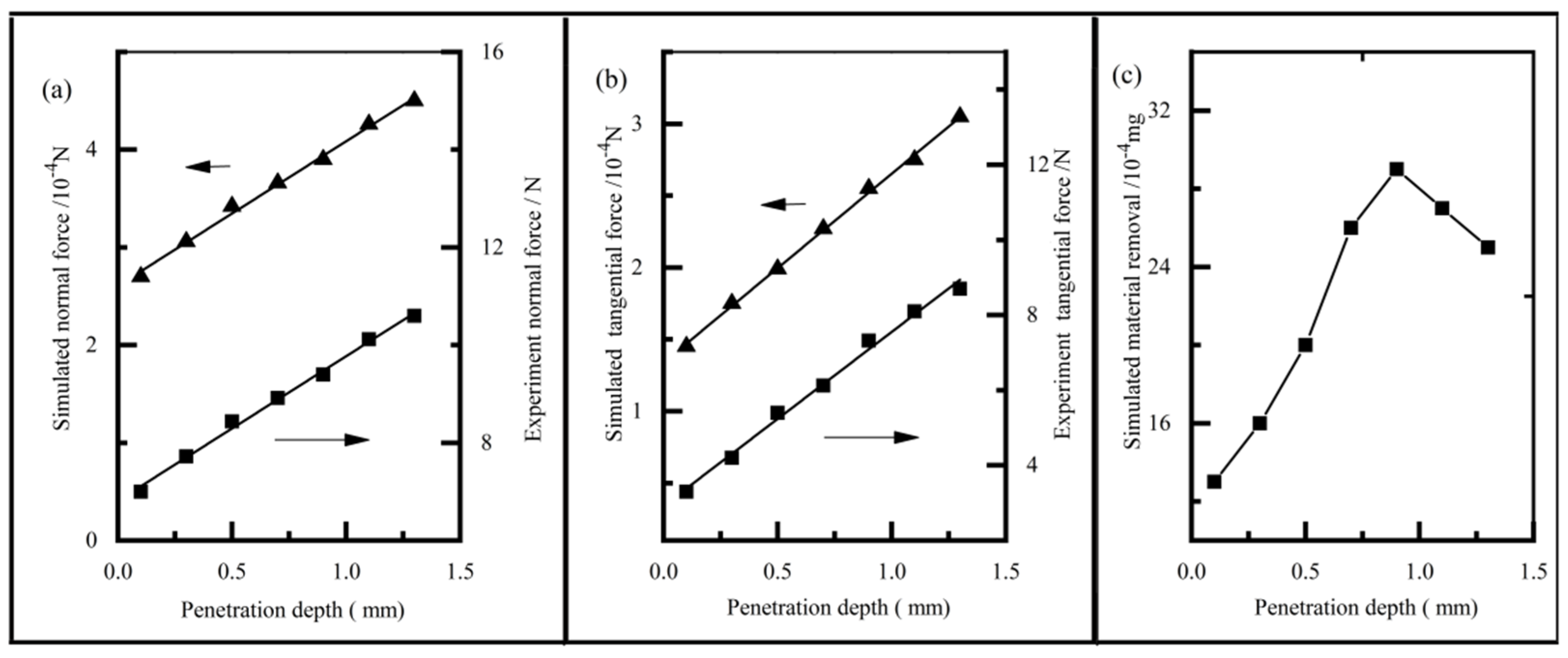
4.2. Aluminium Alloy Removal Mode
4.3. Brush Force
5. Conclusions
Author Contributions
Funding
Institutional Review Board Statement
Informed Consent Statement
Data Availability Statement
Conflicts of Interest
References
- Kim, I.; Kim, H.; Dao, D.K.; Ahn, J.; Jeong, Y. Fatigue resistance improvement of welded joints by bristle roll-brush grinding. In. J. Steel Struct. 2018, 18, 1631–1638. [Google Scholar] [CrossRef]
- Matuszak, J.; Kłonica, M.; Zagórski, I. Measurements of forces and selected surface layer properties of AW-7075 aluminum alloy used in the aviation industry after abrasive machining. Materials 2019, 12, 3707. [Google Scholar] [CrossRef] [Green Version]
- Stango, R.J. Filamentary brushing tools for surface finishing applications. Met. Finish. 2000, 98, 85–94. [Google Scholar] [CrossRef]
- Stango, R.J.; Chen, L.; Cariapa, V. Automated deburring with a filamentary brush: Prescribed burr geometry. J. Mauf. Sci. Eng. 1999, 121, 385–392. [Google Scholar] [CrossRef]
- Cerdà, J.J.; Bona-Casas, C.; Cerrato, A.; Novak, E.V.; Pyanzina, E.S.; Sánchez, P.A.; Kantorovich, S.; Sintes, T. Magnetic responsive brushes under flow in strongly confined slits: External field control of brush structure and flowing particle mixture separation. Soft Matter 2019, 15, 8982–8991. [Google Scholar] [CrossRef] [PubMed]
- Bassett, E.; Köhler, J.; Denkena, B. On the honed cutting edge and its side effects during orthogonal turning operations of AISI1045 with coated WC-Co inserts. CIRP J. Manuf. Sci. Technol. 2012, 5, 108–126. [Google Scholar] [CrossRef]
- Wang, C.; Guo, H.; Zhao, Y.; Sun, Q.; Zhao, L. Statistical Analysis of industrial grinding brush force characteristics based on finite element approach. Math. Probl. Eng. 2018, 2018, 1–9. [Google Scholar] [CrossRef]
- Uhlmann, E.; Hoyer, A. Surface finishing of zirconium dioxide with abrasive brushing tools. Machines 2020, 8, 89. [Google Scholar] [CrossRef]
- Overholser, R.W.; Stango, R.J.; Fournelle, R.A. Morphology of metal surface generated by nylon/abrasive filament brush. Int. J. Mach. Tools Manuf. 2003, 43, 193–202. [Google Scholar] [CrossRef]
- Raymond, N.; Hill, S.; Soshi, M. Characterization of surface polishing with spindle mounted abrasive disk-type filament tool for manufacturing of machine tool sliding guideways. Int. J. Adv. Manuf. Technol. 2016, 86, 2069–2082. [Google Scholar] [CrossRef]
- Nicholas, R.; Soshi, M. Surface polishing of hardened grey cast iron with a compliant abrasive filament tool. Procedia CIRP 2016, 46, 205–208. [Google Scholar]
- Mathai, G.; Melkote, S. Effect of process parameters on the rate of abrasive assisted brush deburring of microgrooves. Int. J. Mach. Tools Manuf. 2012, 57, 46–52. [Google Scholar] [CrossRef]
- Mathai, G.; Melkote, S.; Rosen, D. Material removal during abrasive impregnated brush deburring of micromilled grooves in NiTi foils. Int. J. Mach. Tools Manuf. 2013, 72, 37–49. [Google Scholar] [CrossRef]
- Novotný, F.; Horák, M.; Starý, M. Abrasive cylindrical brush behaviour in surface processing. Int. J. Mach. Tools Manuf. 2017, 118, 61–72. [Google Scholar] [CrossRef]
- Wang, C.; Sun, Q.; Xu, L. Analysis of helical abrasive brush filament force characteristics for surface treatment processes. Adv. Mech. Eng. 2017, 9, 1–8. [Google Scholar] [CrossRef]
- Du, M.; Li, Z.; Dong, X.; Feng, L.; Fan, C. Single pyramid-shaped particle impact on metallic surfaces: A 3D numerical simulation and experiment. Tribol. Lett. 2019, 67, 108–115. [Google Scholar] [CrossRef]
- Kumar, N.; Shukla, M. Finite element analysis of multi-particle impact on erosion in abrasive water jet machining of titanium alloy. J. Comput. Appl. Math. 2012, 236, 4600–4610. [Google Scholar] [CrossRef] [Green Version]
- Rypina, Ł.; Lipiński, D.; Bałasz, B.; Kacalak, W.; Szatkiewicz, T. Analysis and modeling of the micro-cutting process of Ti-6Al-4V titanium alloy with single abrasive grain. Materials 2020, 13, 5835. [Google Scholar] [CrossRef] [PubMed]
- Uhlmann, E.; Sommerfeld, C. Three-dimensional dynamic contact analysis of abrasive filaments with a multi-body system. Procedia CIRP 2018, 72, 615–621. [Google Scholar] [CrossRef]


| No | Revolution Speed (n r/min) | Penetration Depth (Δ mm) | Feed Rate (f m/min) |
|---|---|---|---|
| 1 | 500 | 0.1 | 3 |
| 2 | 1000 | 0.1 | 3 |
| 3 | 2000 | 0.1 | 3 |
| 4 | 3000 | 0.1 | 3 |
| 5 | 4000 | 0.1 | 3 |
| 6 | 5000 | 0.1 | 3 |
| 7 | 3000 | 0.3 | 3 |
| 8 | 3000 | 0.5 | 3 |
| 9 | 3000 | 0.7 | 3 |
| 10 | 3000 | 0.9 | 3 |
| 11 | 3000 | 1.1 | 3 |
| 12 | 3000 | 1.3 | 3 |
| 13 | 1000 | 0.1 | 1 |
| 14 | 3000 | 0.1 | 1 |
| 15 | 3000 | 0.5 | 1 |
Publisher’s Note: MDPI stays neutral with regard to jurisdictional claims in published maps and institutional affiliations. |
© 2021 by the authors. Licensee MDPI, Basel, Switzerland. This article is an open access article distributed under the terms and conditions of the Creative Commons Attribution (CC BY) license (https://creativecommons.org/licenses/by/4.0/).
Share and Cite
Yuan, X.; Wang, C.; Sun, Q.; Zhao, L. Numerical and Experimental Research on the Brushing Aluminium Alloy Mechanism Using an Abrasive Filament Brush. Materials 2021, 14, 6647. https://doi.org/10.3390/ma14216647
Yuan X, Wang C, Sun Q, Zhao L. Numerical and Experimental Research on the Brushing Aluminium Alloy Mechanism Using an Abrasive Filament Brush. Materials. 2021; 14(21):6647. https://doi.org/10.3390/ma14216647
Chicago/Turabian StyleYuan, Xiuhua, Chong Wang, Qun Sun, and Ling Zhao. 2021. "Numerical and Experimental Research on the Brushing Aluminium Alloy Mechanism Using an Abrasive Filament Brush" Materials 14, no. 21: 6647. https://doi.org/10.3390/ma14216647
APA StyleYuan, X., Wang, C., Sun, Q., & Zhao, L. (2021). Numerical and Experimental Research on the Brushing Aluminium Alloy Mechanism Using an Abrasive Filament Brush. Materials, 14(21), 6647. https://doi.org/10.3390/ma14216647