
Strength Parameters of Clay Brick Walls with Various Directions of Force

 ,
,  ,
,  ,
,  , , and
Abstract
:1. Introduction
2. Materials and Methods
2.1. Materials
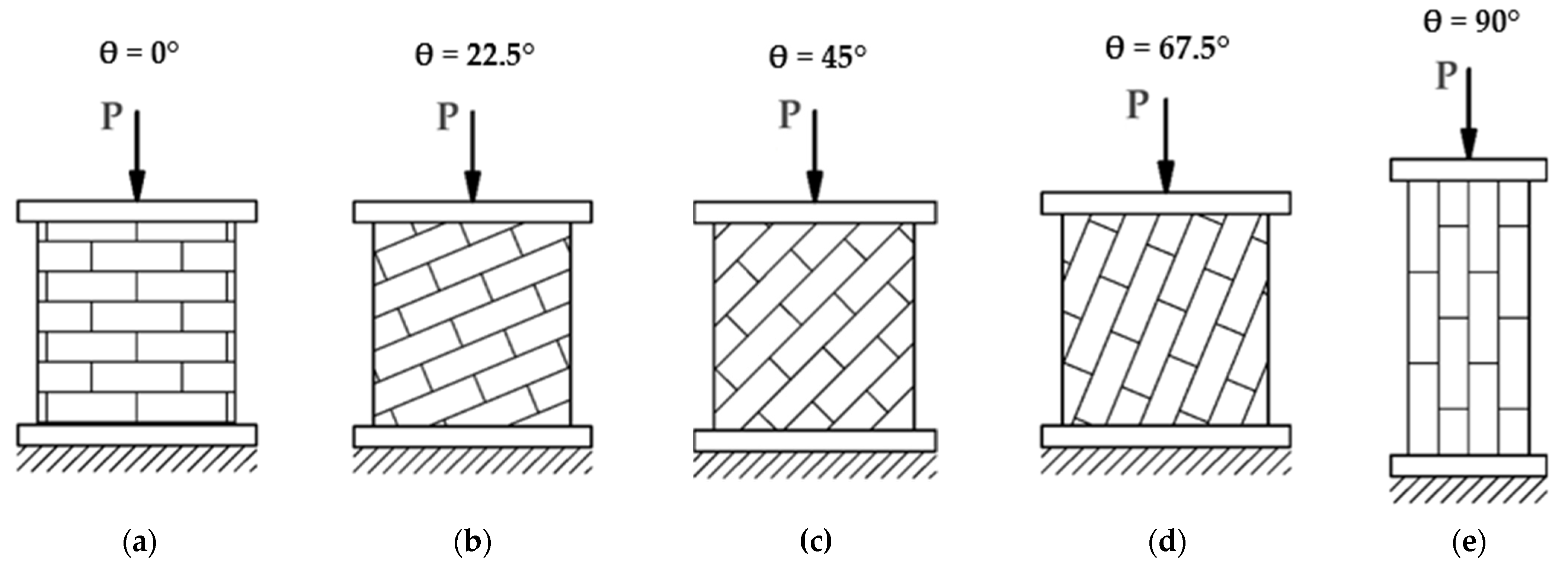
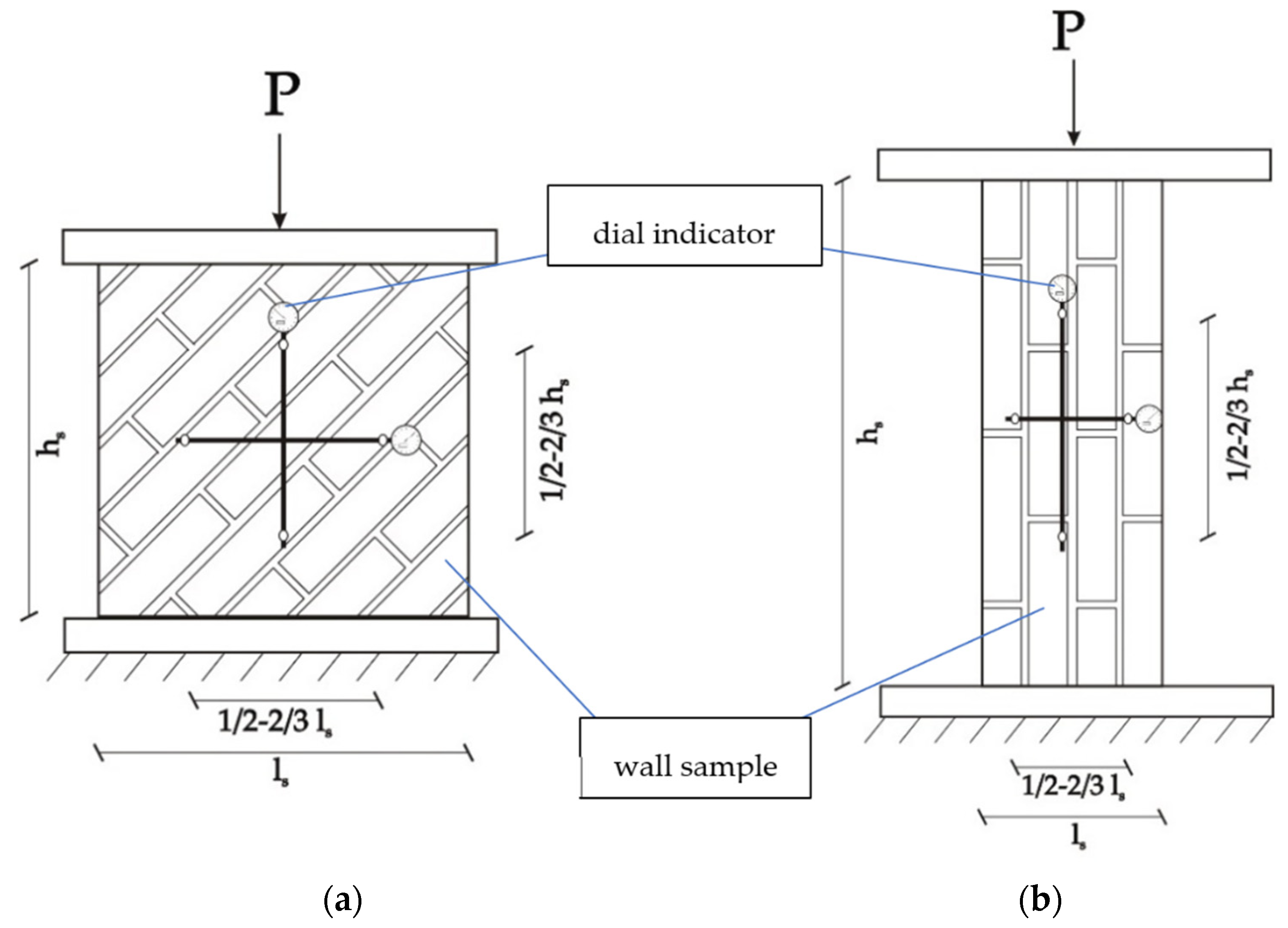
2.2. Methods
3. Results and Discussion
3.1. Results of Compressive Strength Tests
3.2. Results of Deformation, Young’s Modulus, and Poisson’s Coefficient Tests
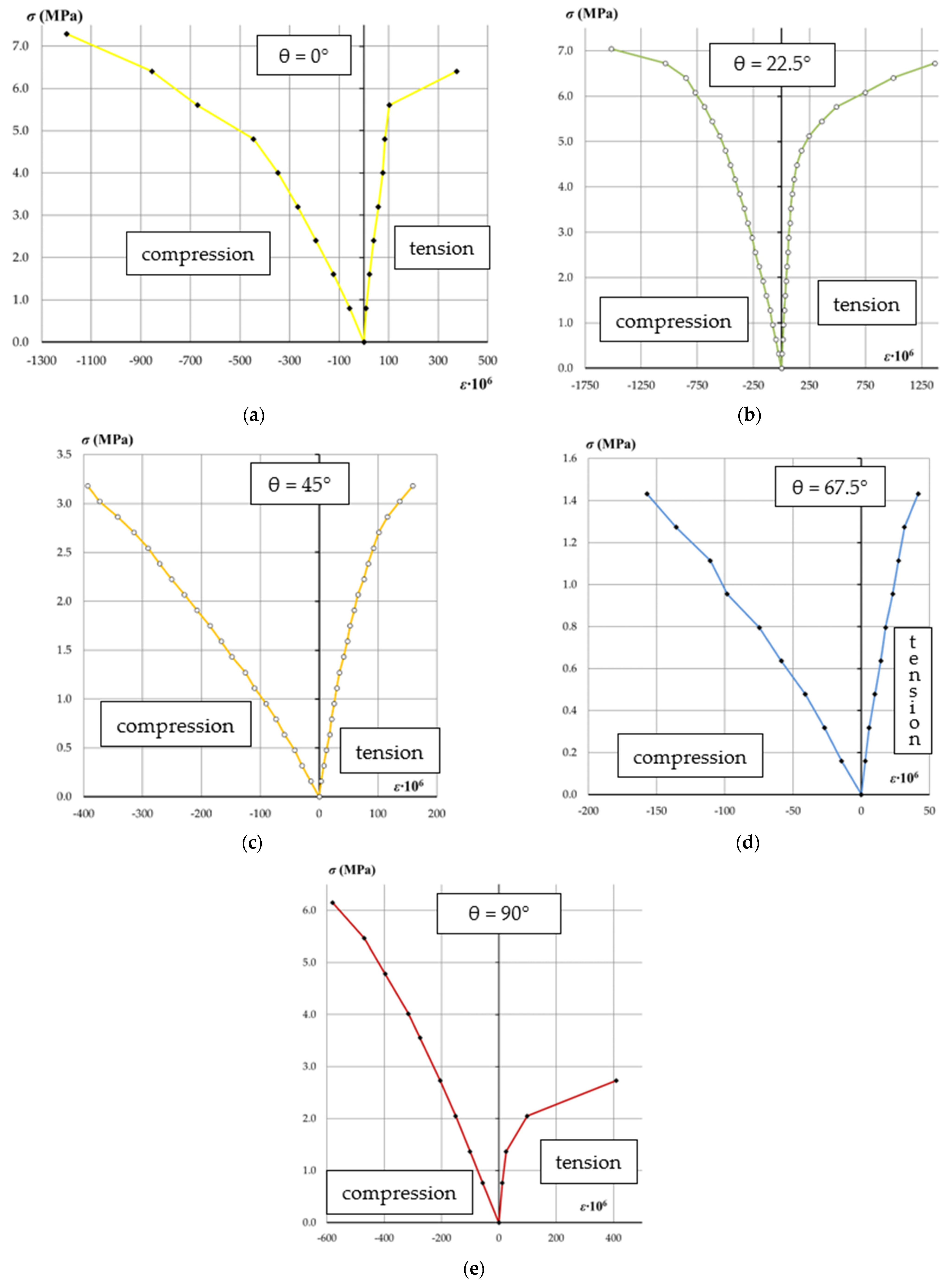
3.2.1. Stress–Strain Dependencies
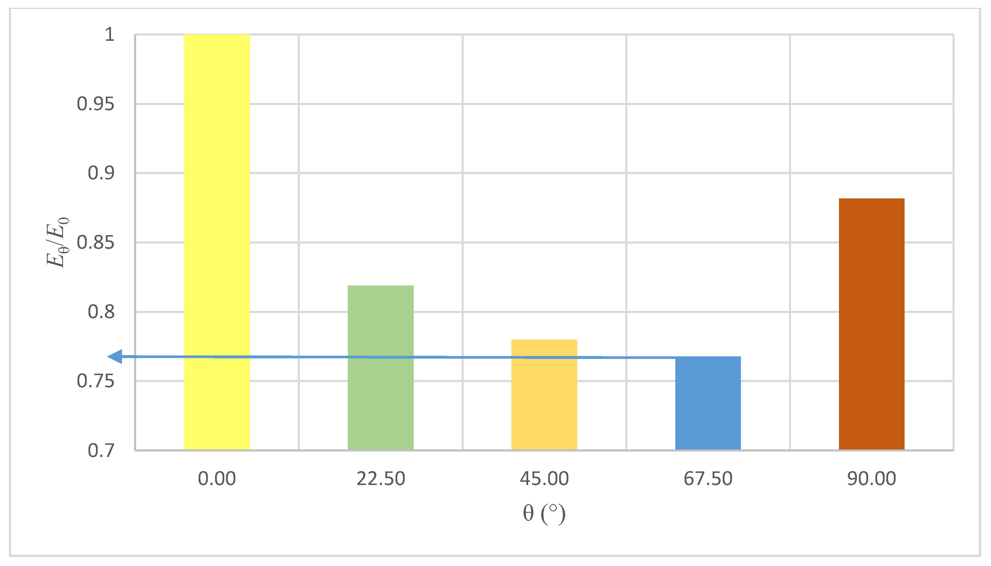
3.2.2. Young Modulus Measurements
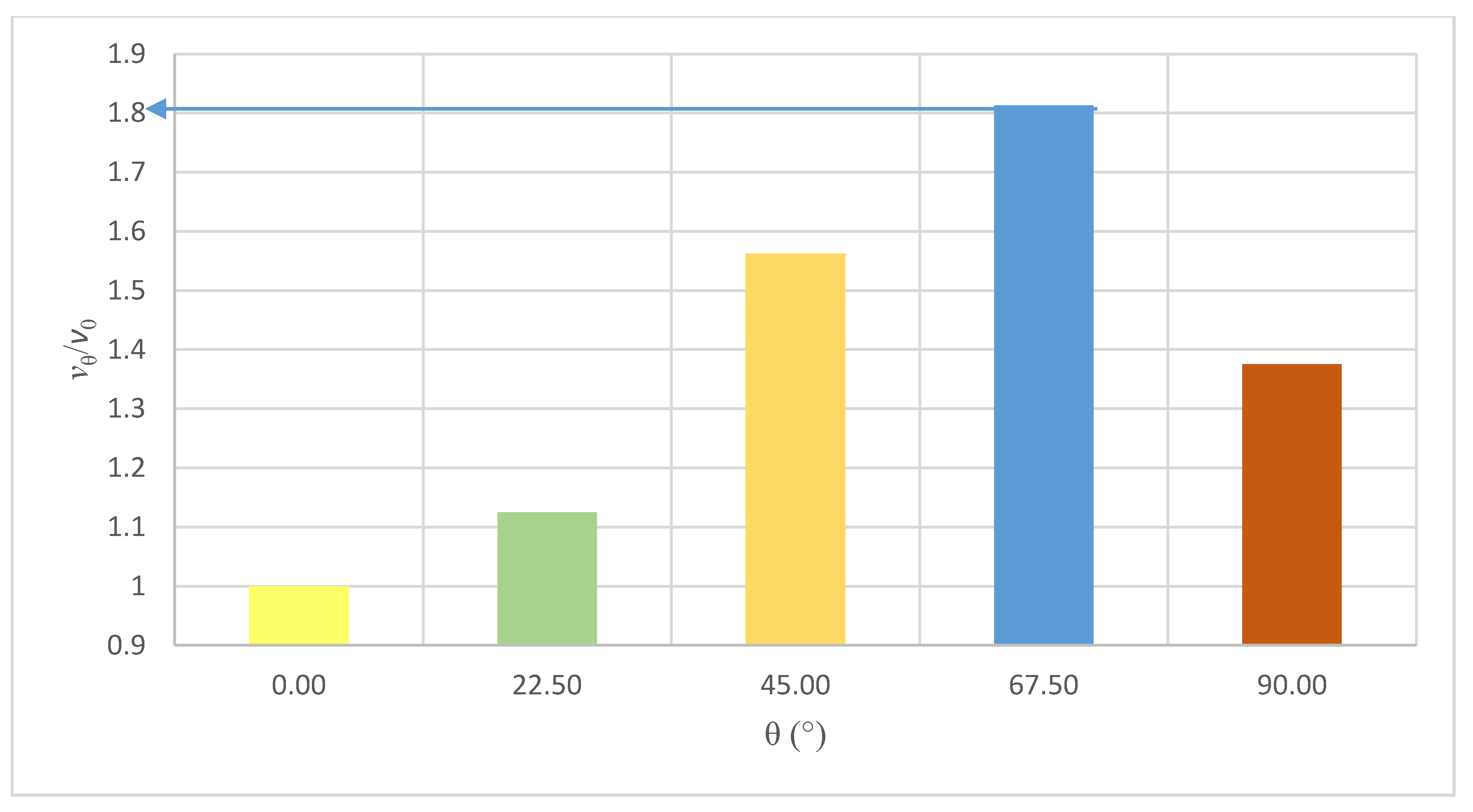
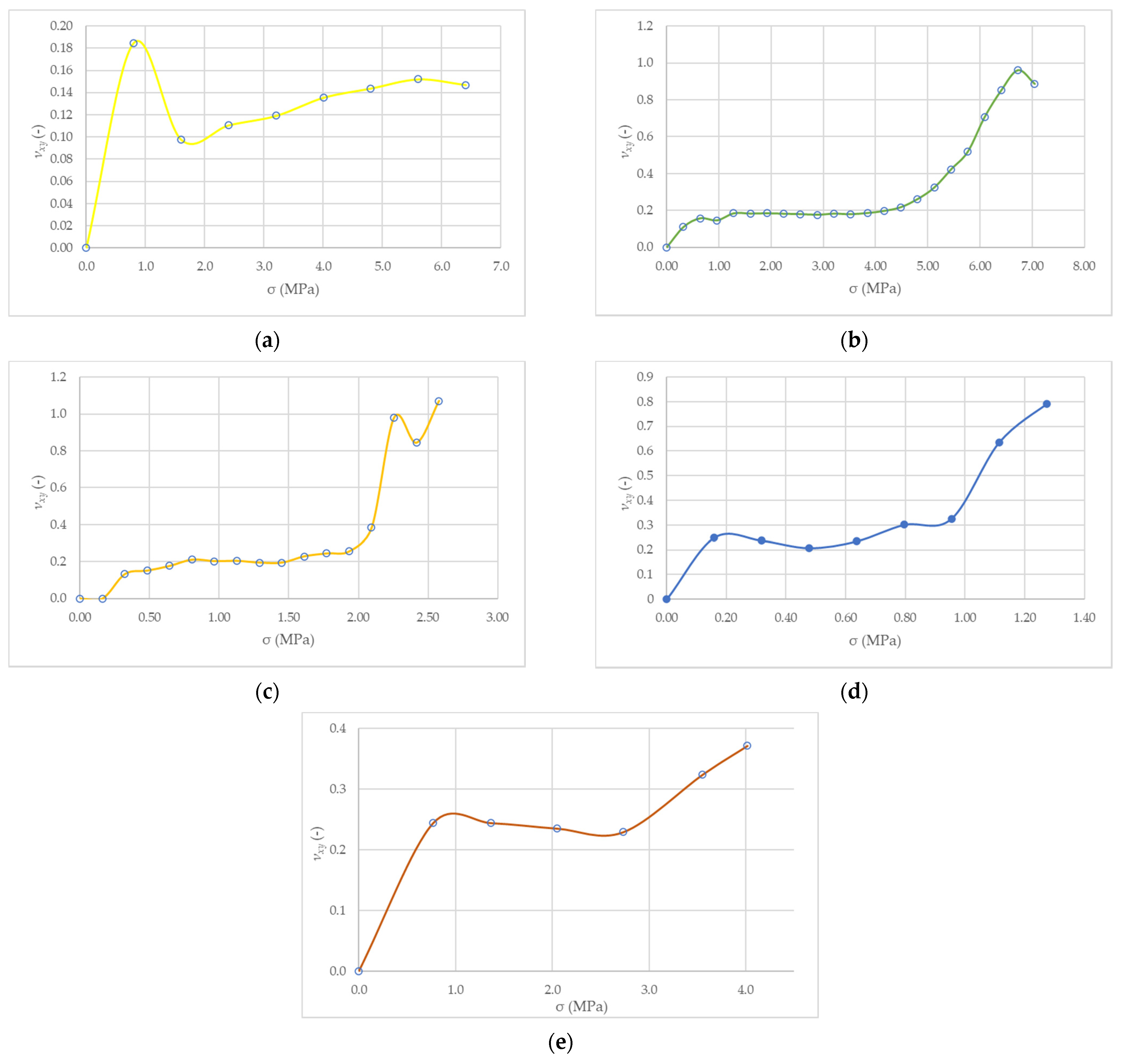
3.2.3. Measurements of the Poisson’s ratio
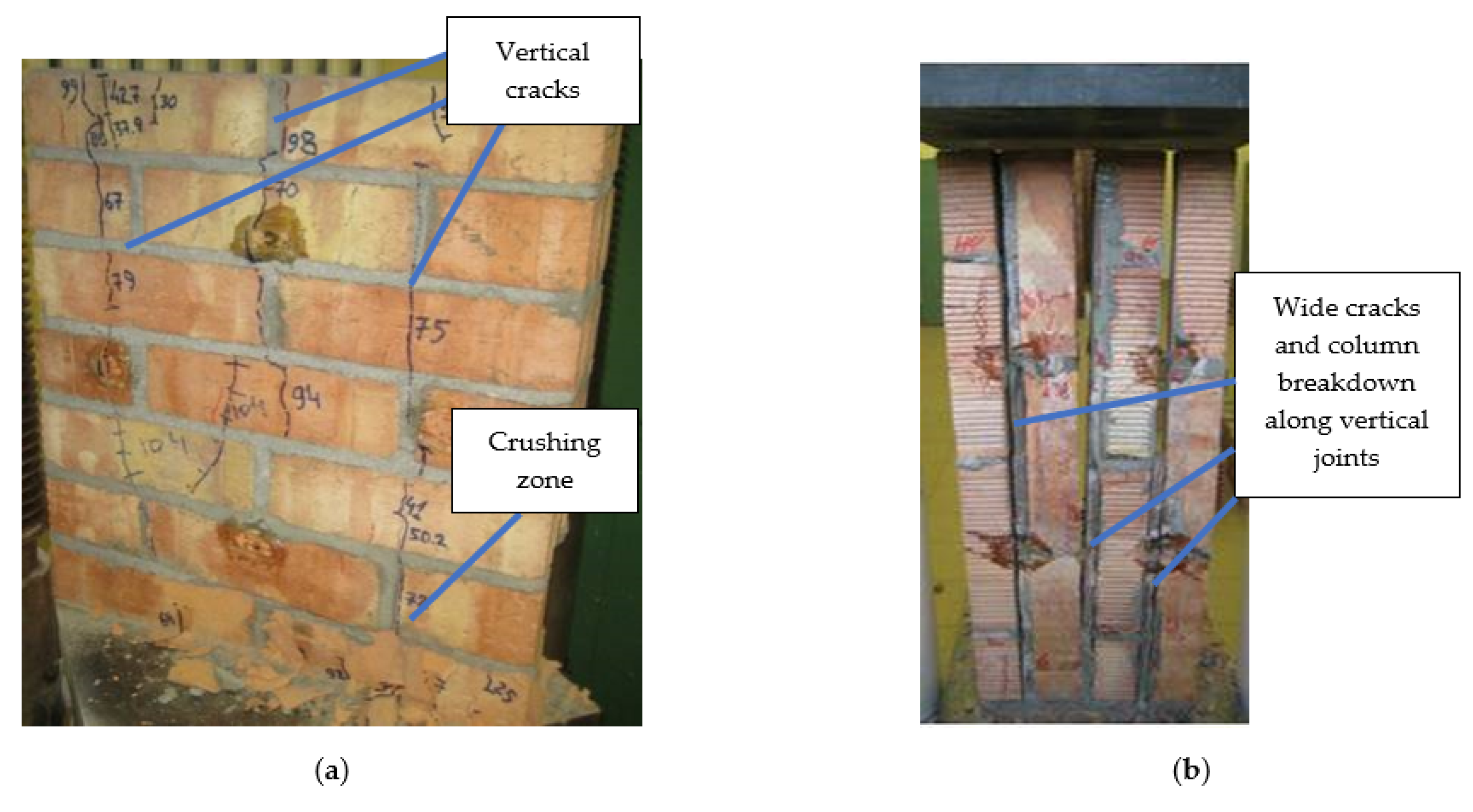
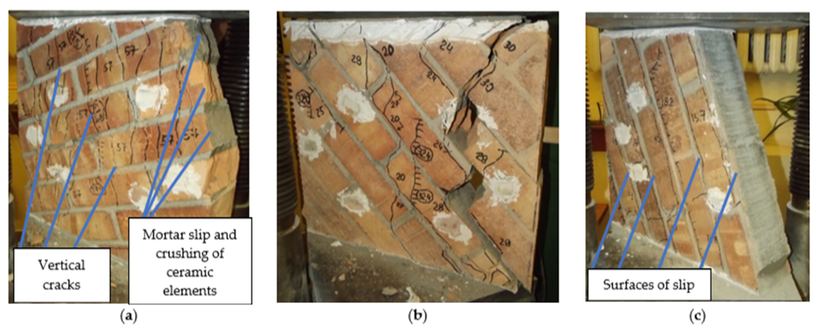
3.3. Failure Mechanism
3.4. General Discussion of the Results
4. Conclusions
- The mechanical properties of the clay brick walls significantly depend on the angle of the compressive force.
- On the basis of the performed tests, the dependencies allowed for the calculation of the mechanical properties for the designed brick walls operating in a uniaxial state of compressive loads were determined.
- The results obtained, together with the results of other studies, allowed a better understand of the problem regarding the degree of anisotropy in the masonry. The results allowed assessing the significance of strength loss for cases with the load applied at an angle to the bed joints.
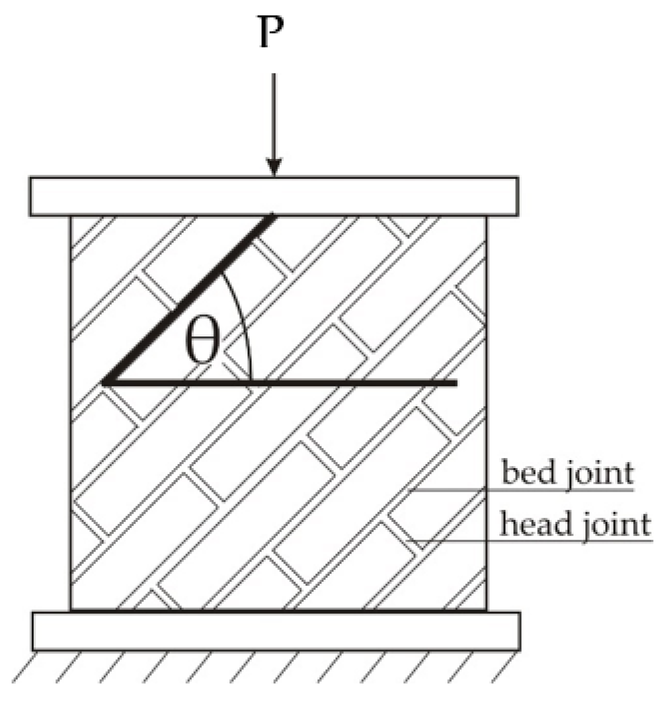
- A minimal compressive strength has been obtained for the load acting at an angle θ = 67.5°. Its value is limited to 24% of the compressive strength for the load acting parallel to the bed joints (θ = 0°).
- The lowest modulus of elasticity was researched on the walls with the bed joint angle of θ = 67.5°. Its value was evaluated as 77% of the initial value (measured for samples θ = 0°).
- The maximum of the Poisson’s ratio was obtained with angle θ = 67.5°, with coefficient νθ/ν0 = 181%.
- The conducted tests allowed identifying and describing the failure mechanism of the tested wall panels.
Author Contributions
Funding
Institutional Review Board Statement
Informed Consent Statement
Data Availability Statement
Acknowledgments
Conflicts of Interest
References
- Bajno, D.; Bednarz, L.; Matkowski, Z.; Raszczuk, K. Monitoring of Thermal and Moisture Processes in Various Types of External Historical Walls. Materials 2020, 13, 505. [Google Scholar] [CrossRef] [PubMed] [Green Version]
- Liritzis, I.; Al-Otaibi, F.; Kilikoglou, V.; Perdikatsis, V.; Polychroniadou, E.; Drivaliari, A. Mortar analysis of wall painting at Amfissa Cathedral for conservation-restoration purposes. Mediterr. Archaeol. Archaeom. 2015, 3, 301–311. [Google Scholar] [CrossRef]
- Michalopoulou, A.; Maravelaki, N.P.; Stefanis, N.A.; Theoulakis, P.; Andreou, S.; Kilikoglou, V.; Karatasios, I. Evaluation of nanolime dispersions for the protection of archeological clay-based building materials. Mediterr. Archaeol. Archaeom. 2020, 3, 221–242. [Google Scholar] [CrossRef]
- PN-EN 1996-1-1+A1 Eurocode 6—Design of Masonry Structures—Part 1-1: General Rules for Reinforced and Unreinforced Masonry Structures; European Committee for Standardization: Brussels, Belgium, 2013.
- Małyszko, L.; Jemioło, S.; Bilko, P.; Gajewski, M. FEM and Constitutive Modelling in Failure Analysis of Masonry Structures. Implementation and Examples; University of Warmia and Mazury: Olsztyn, Poland, 2015. [Google Scholar]
- Małyszko, L.; Orłowicz, R. Konstrukcje Murowe. Zarysowania i Naprawy. (Structural Masonry. Cracks and Repairs); University of Warmia and Mazury: Olsztyn, Poland, 2000. [Google Scholar]
- Jemioło, S.; Małyszko, L. MES i Modelowanie Konstytutywne w Analizie Zniszczenia Konstrukcji Murowych. Tom 1. Podstawy Teoretyczne; University of Warmia and Mazury: Olsztyn, Poland, 2013. [Google Scholar]
- Abdelmoneim Elamin Mohamad, A.-B.; Chen, Z. Experimental and Numerical Analysis of the Compressive and Shear Behavior for a New Type of Self-Insulating Concrete Masonry System. Appl. Sci. 2016, 6, 245. [Google Scholar] [CrossRef] [Green Version]
- Lin, K.; Totoev, Y.Z.; Liu, H.; Wei, C. Experimental Characteristics of Dry Stack Masonry under Compression and Shear Loading. Materials 2015, 8, 8731–8744. [Google Scholar] [CrossRef] [Green Version]
- Jasiński, R.; Drobiec, Ł.; Mazur, W. Validation of Selected Non-Destructive Methods for Determining the Compressive Strength of Masonry Units Made of Autoclaved Aerated Concrete. Materials 2019, 12, 389. [Google Scholar] [CrossRef] [PubMed] [Green Version]
- Lourenco, P.B. Computations on historic masonry structures. Prog. Struct. Eng. Mater. 2002, 4, 301–319. [Google Scholar] [CrossRef]
- Beconcini, M.L.; Croce, P.; Formichi, P.; Landi, F.; Puccini, B. Experimental Evaluation of Shear Behavior of Stone Masonry Wall. Materials 2021, 14, 2313. [Google Scholar] [CrossRef] [PubMed]
- Malomo, D.; DeJong, M.J. A Macro-Distinct Element Model (M-DEM) for out-of-plane analysis of unreinforced masonry structures. Eng. Struct. June 2021, 244, 112754. [Google Scholar] [CrossRef]
- Lourenço, P.B.; Rots, J.G.; Blaauwendraad, J. Continuum model for masonry: Parameter estimation and validation. J. Struct. Eng. 1998, 124, 642–652. [Google Scholar] [CrossRef]
- Celano, T.; Argiento, L.U.; Ceroni, F.; Casapulla, C. In-Plane Behaviour of Masonry Walls: Numerical Analysis and Design Formulations. Materials 2021, 14, 5780. [Google Scholar] [CrossRef]
- Croce, P.; Beconcini, M.L.; Formichi, P.; Landi, F.; Puccini, B.; Zotti, V. Bayesian Methodology for Probabilistic Description of Mechanical Parameters of Masonry Walls. ASCE-ASME J. Risk Uncertain. Eng. Syst. Part A Civ. Eng. 2021, 7, 04021008. [Google Scholar] [CrossRef]
- Zhang, S.; Mohadeseh, S.; Mousavi, T.; Richart, N.; Molinari, J.F.; Beyer, K. Micro-mechanical finite element modeling of diagonal compression test for historical stone masonry structure. Int. J. Solids Struct. 2017, 112, 122–132. [Google Scholar] [CrossRef]
- Mojsilović, N. A Discussion of Masonry Characteristics Derived from Compression Tests. In Proceedings of the 10TH Canadian Masonry Symposium, Banff, AB, Canada, 8–12 June 2005. [Google Scholar]
- Senthivel, R.; Sinha, S.N.; Madan, A. Influence of bed joint orientation on the stress-strain characteristics of sand plast brick masonry under uniaxial compression and tension. In Proceedings of the 12TH International Brick/Block Masonry Conference, New Delhi, India, 25–28 June 2000. [Google Scholar]
- Jasiński, R. Research on the Influence of Bed Joint Reinforcement on Strength and Deformability of Masonry Shear Walls. Materials 2019, 12, 2543. [Google Scholar] [CrossRef] [Green Version]
- ASTM E72 1989 Standard Tests for Conducting Strength Tests on Panels for Building Construction; American Society for Testing and Materials: West Conshohocken, PA, USA, 1989.
- Małyszko, L. Modelowanie Zniszczenia w Konstrukcjach Murowych z Uwzględnieniem Anizotropii; Uniwersytet Warmińsko-Mazurski: Olsztyn, Poland, 2005; p. 157. [Google Scholar]
- Jasiński, R. Nośność I Odkształcalność Zbrojonych Ścian Murowych Ścinanych Poziomo (Strenght and Deformability of Reinforced Clay Brick Masonry Horyzonatally Sheared); Silesian University of Technology: Gliwice, Poland, 2005. [Google Scholar]
- Drobiec, Ł.; Kubica, J.; Piekarczyk, A. Some Remarks on Poisson’s Ratio of Unreinforced Clay Brick Masonry. In Proceedings of the 77th International Scientific Conference; BMO: Brno, The Czech Republic, 1999; Volume 7.2, pp. 113–116. [Google Scholar]
- Capozucca, R. Masonry Panels with Different Mortar Joints under Compression. In Proceedings of the 13th International Brick and Block Masonry Conference, Amsterdam, The Netherlands, 4–7 July 2004. [Google Scholar]
- Hoffmann, G.; Schubert, P. Compresslve strength of masonry parallel to the bed joints. In Proceedings of the 10th IB2MaC, Calgary, AB, Canada, 5–7 July 1994. [Google Scholar]
- Sentler, L. Tests of Swedish Masonry. Mason. Int. 1996, 10, 49–54. [Google Scholar]
- Drobiec, Ł.; Piekarczyk, A.; Kubica, J. AAC Bocks Masonry Compressed Perpendicular and Parallel to the Bed Joints. In Proceedings of the 12th International Brick/Block Masonry Conference, New Delhi, India, 25–28 June 2000. [Google Scholar]
- Bednarz, Ł.; Drygała, I.; Dulińska, J.; Jasieńko, J. Study of Materials Behavior in a Monumental Vault Strengthened by a Carbon Net in a Mineral Matrix Subjected to Seismic Influence. Appl. Sci. 2021, 11, 1015. [Google Scholar] [CrossRef]
- Jasienko, J.; Raszczuk, K.; Frąckiewicz, P.; Kleszcz, K.; Bednarz, Ł. Strengthening of masonry rings with composite materials. Herit. Sci. 2021, 9, 11. [Google Scholar] [CrossRef]
- Page, A. The biaxial compressive strength of brick masonry. ICE Proc. 1981, 71, 893–906. [Google Scholar] [CrossRef]
- Dhanasekar, M.; Kleeman, P.; Page, A. Biaxial Stress-strain Relations for Brick Masonry. J. Struct. Eng. ASCE J. Struct. Eng. ASCE 1985, 111, 1085–1100. [Google Scholar] [CrossRef]
- Dhanasekar, M.; Kleeman, P.W.; Page, A.W. The failure of brick masonry under biaxial stresses. ICE Proc. 1985, 79, 295–313. [Google Scholar] [CrossRef]
- Page, A. The strength of brick masonry under biaxial compression-tension. Int. J. Mason. Constr. 1983, 3, 26–31. [Google Scholar]
- Guggisberg, R.; Thürlimann, B. Versuche zur Festlegung der Rechenwerte von Mauerwerksfestigkeiten; Birkhäuser: Basel, Switzerland, 1988. [Google Scholar] [CrossRef] [Green Version]
- Kania, T.; Derkach, V.; Nowak, R. Testing Crack Resistance of Non-Load-Bearing Ceramic Walls with Door Openings. Materials 2021, 14, 1379. [Google Scholar] [CrossRef] [PubMed]
- Drysdale, R.; Hamid, A.; Baker, L. Masonry Structures: Behavior and Design; The Masonry Society; Prentice Hall: Englewood Cliffs, NJ, USA, 1999. [Google Scholar]
- Radosław, J. Badania i Modelowanie Murowych Ścian Usztywniających. Research and Modeling of Masonry Shear Walls; Silesian University of Technology: Gliwice, Poland, 2017. [Google Scholar]
- Hendry, A.W.; Sinha, B.P.; Davies, S.R. Design of Masonry Structures; E & FN Spon: London, UK, 2004. [Google Scholar]
- Ng’Andu, B.M. Bracing Steel Frames with Calcium Silicate Element Walls; Technische Universiteit Eindhoven: Eindhoven, The Netherlands, 2006. [Google Scholar]
- ASTM E519/E519M-21, Standard Test Method for Diagonal Tension (Shear) in Masonry Assemblages; ASTM International: West Conshohocken, PA, USA, 2021.
- Ali, A.A.A.; Jony, H.H. Shear Wall Analysis Using Framework Method: Comparison with Shell Element Method and Column Analogy. Eng. Technol. J. 2013, 31, 1949–1961. [Google Scholar]
- Roca, P. Assessment of masonry shear-walls by simple equilibrium models. Constr. Build. Mater. 2006, 20, 229–238. [Google Scholar] [CrossRef]
- Roca, P.; Viviescas, Á.; Lobato, M.; Gomez, C.; Serra, I. Capacity of Shear Walls by Simple Equilibrium Models. Int. J. Archit. Herit. 2011, 5, 412–435. [Google Scholar] [CrossRef]
- Kok Choon, V. Bracing Capacity of Partially Grounted Concrete Masonry Walls with Openings; Department of Civil and Enviromental Engineering, The University of Auckland: Auckland, New Zeland, 2006. [Google Scholar]
- En 772-1+a1 Methods of Test for Masonry Units. Determination of Compressive Strength; European Committee for Standardization: Brussels, Belgium, 2015.
- EN 1015-11 Methods of Test for Mortar for Masonry. Determination of Flexural and Compressive Strength of Hardened Mortar; European Committee for Standardization: Brussels, Belgium, 2020.
- EN 1052-3 Methods of Test for Masonry. Determination of Initial Shear Strength; European Committee for Standardization: Brussels, Belgium, 2002.
- EN 1052-1 Methods of Test for Masonry. Determination of Compressive Strength; European Committee for Standardization: Brussels, Belgium, 1998.
- RILEM TC 76-LUM General recommendations for methods of testing load-bearing masonry. RILEM Publ. SARL 1988, 21, 123.


| No. | Load Diagram | Test | Material | Result |
|---|---|---|---|---|
| A |  | Compressive strength (EN 772-1 [46]) | Brick | fb = 44.1 MPa |
| B |  | Young and Poisson | Brick | E = 11,850 MPa ν = 0.11 |
| C |  | Flexural strength | Brick | f = 3.2 MPa |
| D |  | Flexural strength (EN 1015-11 [47]) | Mortar | f = 3.3 MPa |
| E |  | Compressive strength (EN 1015-11 [47]) | Mortar | fm = 10.9 MPa |
| F |  | Young and Poisson | Mortar | E = 10,580 MPa ν = 0.17 |
| G |  | Shear strength (EN 1052-3 [48]) | Masonry | fvo = 0.50 MPa tg(α) = 0.5 |
| Load Angle | Ordinal No | Observed Compressive Strength | Mean Compressive Strength | |
|---|---|---|---|---|
| fc,obs (MPa) | fc, mean (MPa) | Coefficient of variation CoV (%) | ||
| θ = 0° | A1 | 16.79 | 15.1 | 9.0 |
| A2 | 16.94 | |||
| A3 | 12.16 | |||
| A4 | 13.98 | |||
| A5 | 16.14 | |||
| A6 | 13.18 | |||
| A7 | 16.39 | |||
| A8 | 15.08 | |||
| θ = 22.5° | B1 | 6.69 | 8.0 | 11.5 |
| B2 | 7.78 | |||
| B3 | 9.27 | |||
| B4 | 8.12 | |||
| B5 | 7.99 | |||
| θ = 45° | C1 | 5.72 | 4.9 | 13.0 |
| C2 | 3.95 | |||
| C3 | 4.96 | |||
| C4 | 5.16 | |||
| C5 | 4.83 | |||
| θ = 67.5° | D1 | 3.78 | 3.6 | 18.1 |
| D2 | 2.58 | |||
| D3 | 3.42 | |||
| D4 | 4.08 | |||
| D5 | 4.22 | |||
| θ = 90° | E1 | 12.44 | 11.4 | 7.4 |
| E2 | 10.89 | |||
| E3 | 10.31 | |||
| E4 | 11.96 | |||
| E5 | 11.40 | |||
| Load Angle | Ordinal No. | Observed Young’s Modulus in Compression | Mean Value of The Young’s Modulus | |
|---|---|---|---|---|
| Ey,obs (MPa) | Ey,mean (MPa) | CoV (%) | ||
| θ = 0° | A1 | 9058 | 11,146 | 17.81 |
| A2 | 8800 | |||
| A3 | 8750 | |||
| A4 | 12,605 | |||
| A5 | 13,330 | |||
| A6 | 12,719 | |||
| A7 | 12,759 | |||
| A8 | 11,144 | |||
| θ = 22.5° | B1 | 8327 | 9127 | 15.16 |
| B2 | 7982 | |||
| B3 | 10,954 | |||
| B4 | 10,272 | |||
| B5 | 8099 | |||
| θ = 45° | C1 | 7393 | 8696 | 11.16 |
| C2 | 9240 | |||
| C3 | 9454 | |||
| C4 | 7921 | |||
| C5 | 9470 | |||
| θ = 67.5° | D1 | 10,222 | 8563 | 15.77 |
| D2 | 9247 | |||
| D3 | 6685 | |||
| D4 | 8782 | |||
| D5 | 7863 | |||
| θ = 90° | E1 | 10,100 | 9827 | 2.89 |
| E2 | 10,000 | |||
| E3 | 9380 | |||
| E4 | 9932 | |||
| E5 | 9747 | |||
| Load Angle | Ordinal No. | Observed Poisson’s Ratio | Mean Poisson’s Ratio | |
|---|---|---|---|---|
| νxy,obs | νxy,mean | CoV (%) | ||
| θ = 0° | A1 | 0.16 | 0.156 | 7.40 |
| A2 | 0.17 | |||
| A3 | 0.14 | |||
| A4 | 0.16 | |||
| A5 | 0.15 | |||
| θ = 22.5° | B1 | 0.16 | 0.182 | 23.76 |
| B2 | 0.15 | |||
| B3 | 0.25 | |||
| B4 | 0.15 | |||
| B5 | 0.2 | |||
| θ = 45° | C1 | 0.26 | 0.246 | 14.82 |
| C2 | 0.27 | |||
| C3 | 0.19 | |||
| C4 | 0.23 | |||
| C5 | 0.28 | |||
| θ = 67.5° | D1 | 0.24 | 0.290 | 12.19 |
| D2 | 0.30 | |||
| D3 | 0.27 | |||
| D4 | 0.31 | |||
| D5 | 0.33 | |||
| θ = 90° | E1 | 0.24 | 0.220 | 10.66 |
| E2 | 0.19 | |||
| E3 | 0.23 | |||
| E4 | 0.24 | |||
| E5 | 0.20 | |||
Publisher’s Note: MDPI stays neutral with regard to jurisdictional claims in published maps and institutional affiliations. |
© 2021 by the authors. Licensee MDPI, Basel, Switzerland. This article is an open access article distributed under the terms and conditions of the Creative Commons Attribution (CC BY) license (https://creativecommons.org/licenses/by/4.0/).
Share and Cite
Nowak, R.; Kania, T.; Derkach, V.; Orłowicz, R.; Halaliuk, A.; Ekiert, E.; Jaworski, R. Strength Parameters of Clay Brick Walls with Various Directions of Force. Materials 2021, 14, 6461. https://doi.org/10.3390/ma14216461
Nowak R, Kania T, Derkach V, Orłowicz R, Halaliuk A, Ekiert E, Jaworski R. Strength Parameters of Clay Brick Walls with Various Directions of Force. Materials. 2021; 14(21):6461. https://doi.org/10.3390/ma14216461
Chicago/Turabian StyleNowak, Rafał, Tomasz Kania, Valery Derkach, Romuald Orłowicz, Anton Halaliuk, Ewa Ekiert, and Rafał Jaworski. 2021. "Strength Parameters of Clay Brick Walls with Various Directions of Force" Materials 14, no. 21: 6461. https://doi.org/10.3390/ma14216461
APA StyleNowak, R., Kania, T., Derkach, V., Orłowicz, R., Halaliuk, A., Ekiert, E., & Jaworski, R. (2021). Strength Parameters of Clay Brick Walls with Various Directions of Force. Materials, 14(21), 6461. https://doi.org/10.3390/ma14216461