
Cutting Forces during Inconel 718 Orthogonal Turn-Milling


Abstract
:1. Introduction
2. Materials and Methods
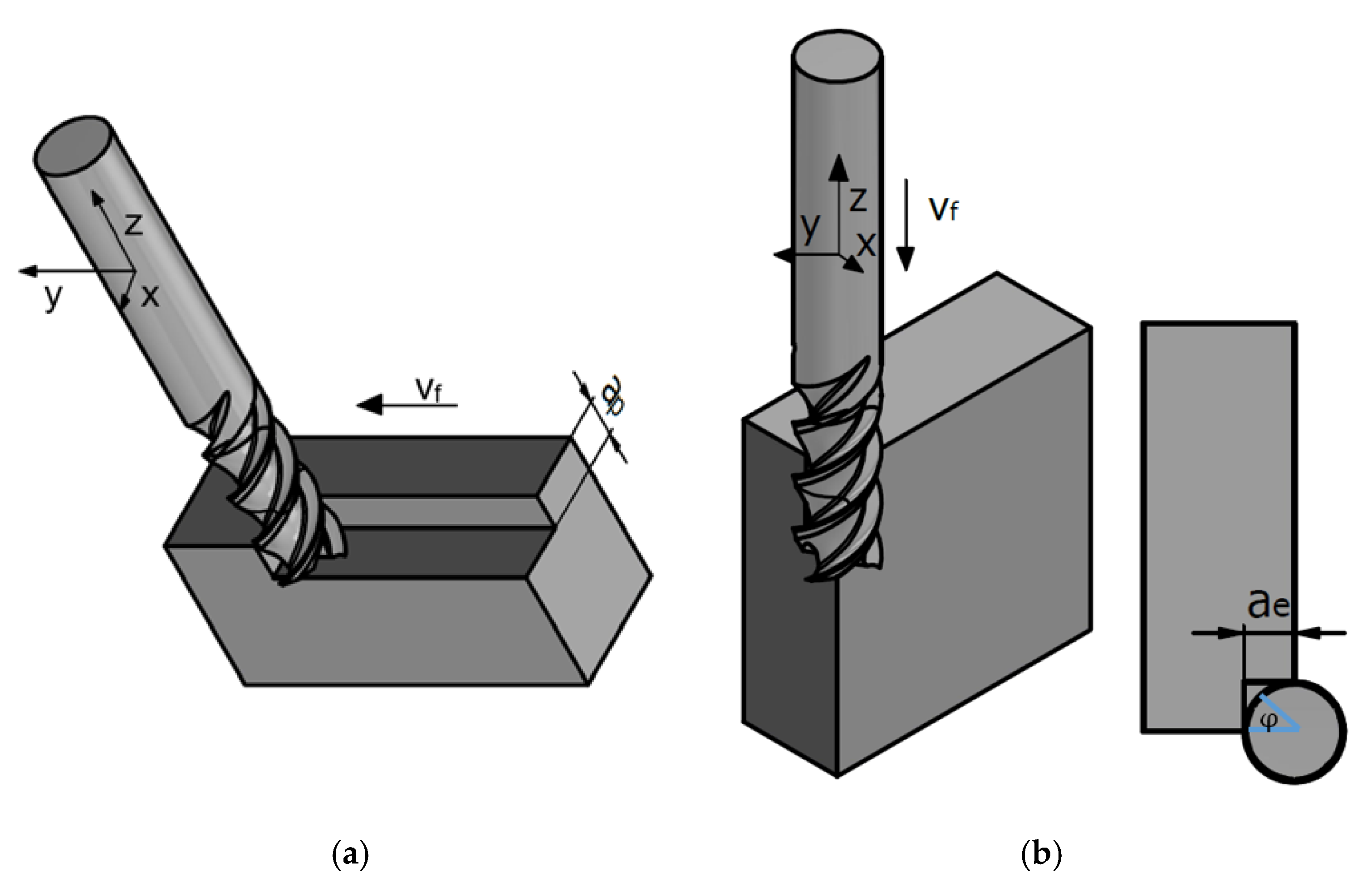
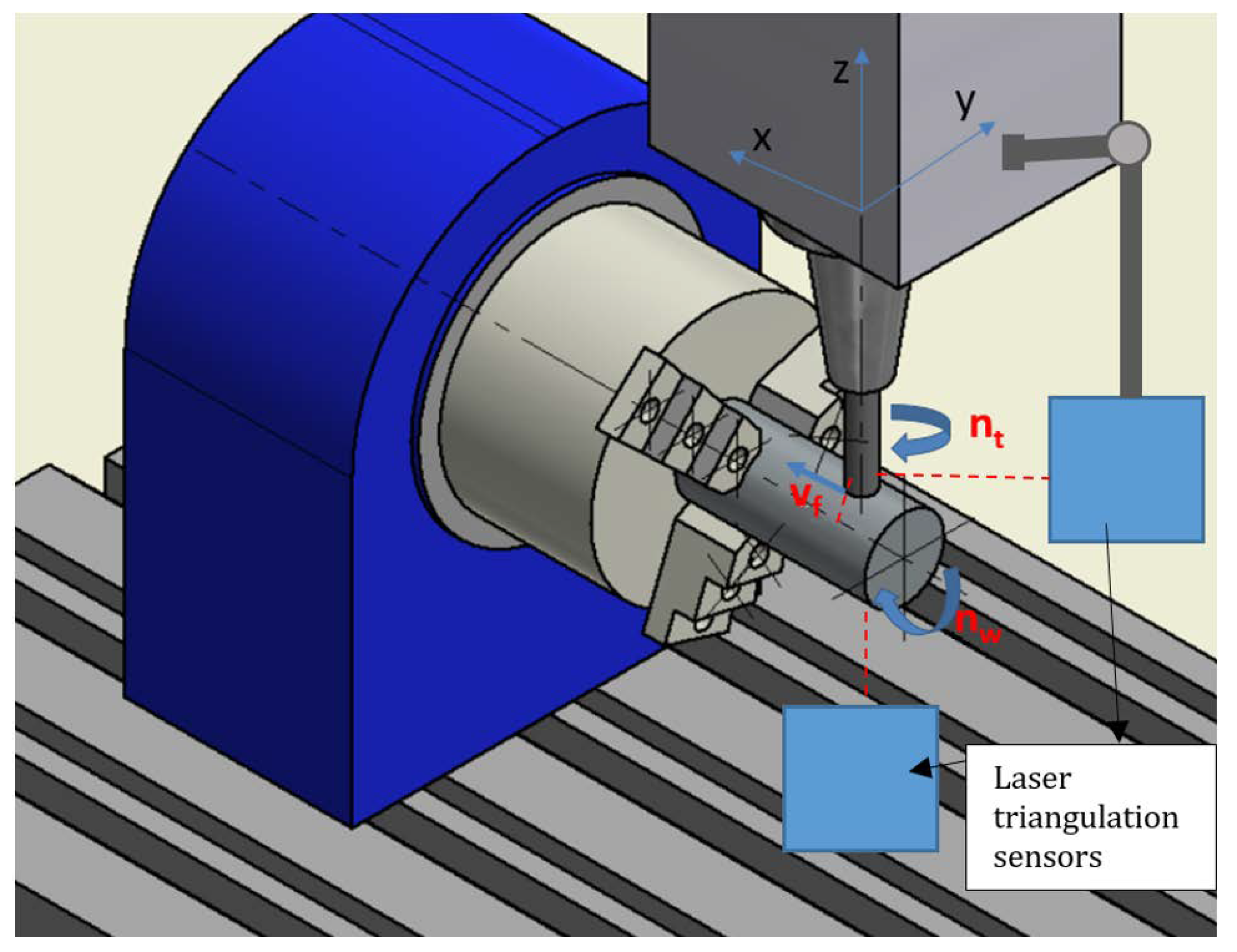
2.1. Kinematic and the Uncut Chip Geometry Model
- vc—cutting speed [m/min]
- va—axial feed speeed [mm/min]
- vt—tangential feed speed [mm/min]
- ft—tangential feed [mm]
- fa—axial feed [mm/workpiece rotation]
- fz—feed per tooth [mm]
- nt—tool rotational speed [rpm]
- nw—workpiece rotational speed [rpm]
- —tool radius [mm]
- Rw—workpiece radius [mm]
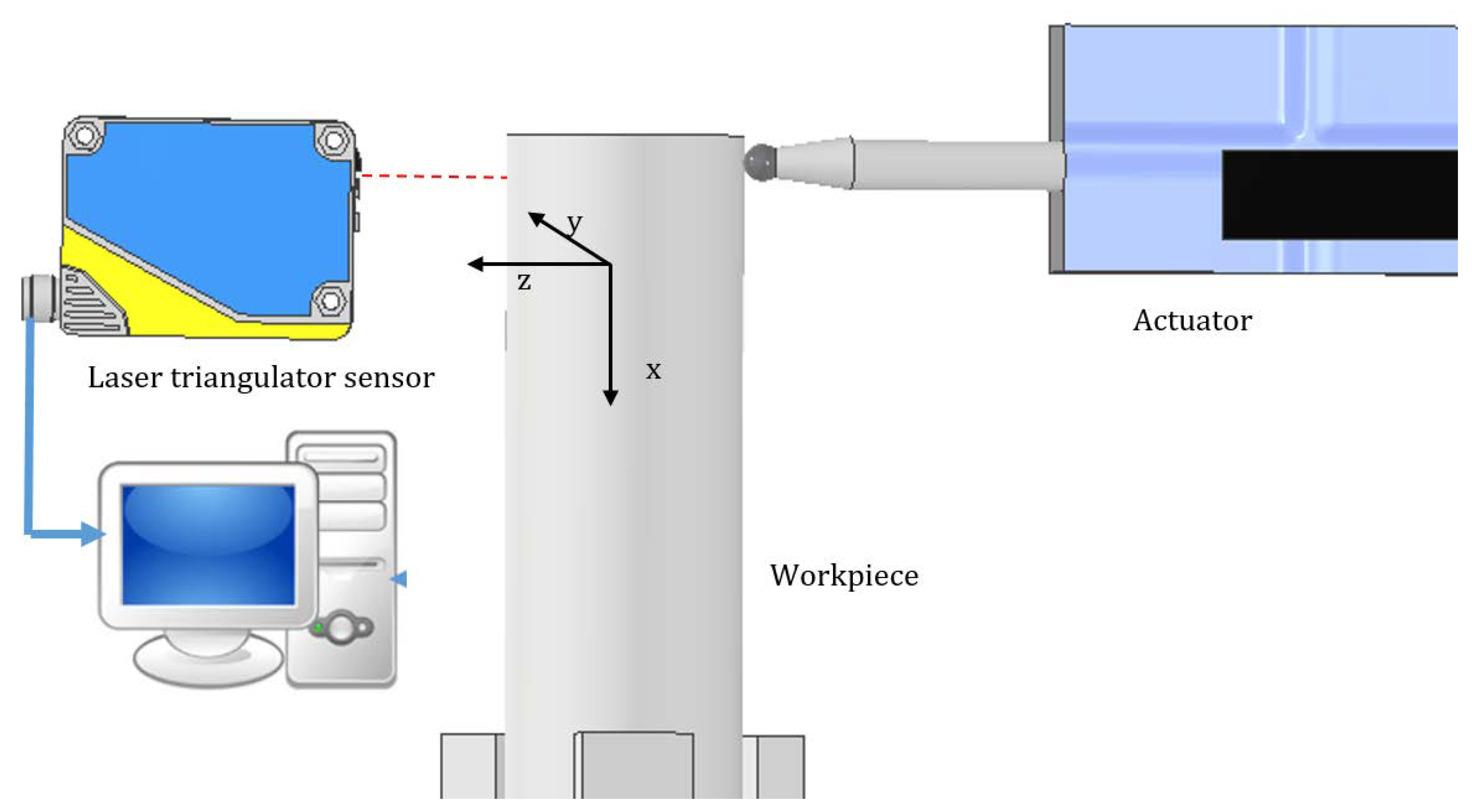
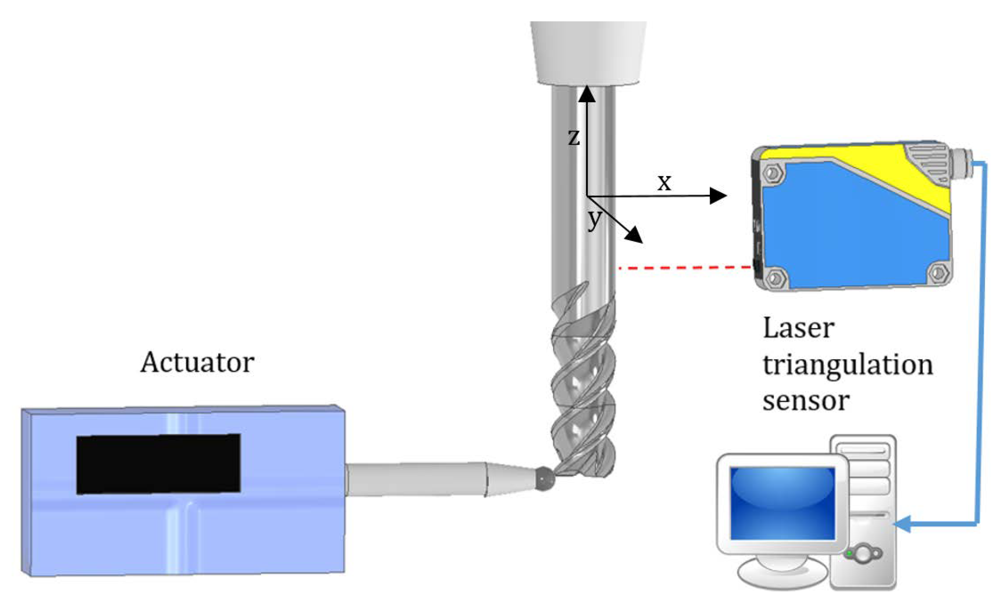
2.2. Stiffness Determination
- —average stifness [N/µm]
- F—applied force [N]
- a—linear displacement [µm]
- n—number of cases
- xz = 2.367 [N/µm]
- xx,y = 3.474 [N/µm].
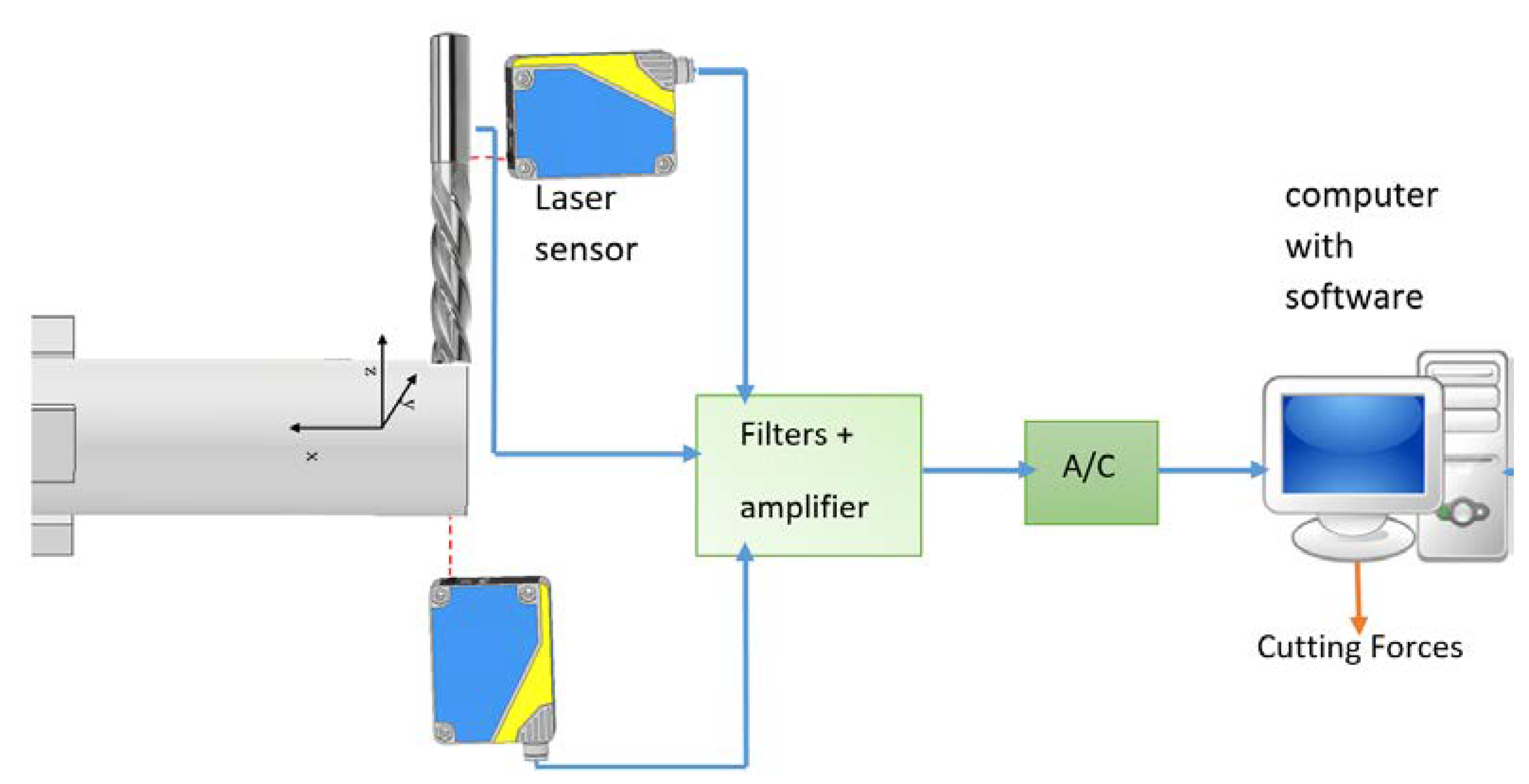
2.3. Calculating Cutting Forces Coefficions
- dFrq—differential of radial force [N]
- dFtq—differential of tangential force [N]
- dFaq—differential of axial force [N]
- Krc, Kre, Ktc, Kte, Kac, Kae—cutting force coefficients [N/mm2]
- e (φ, r)—instantaneous chip thickness [mm]
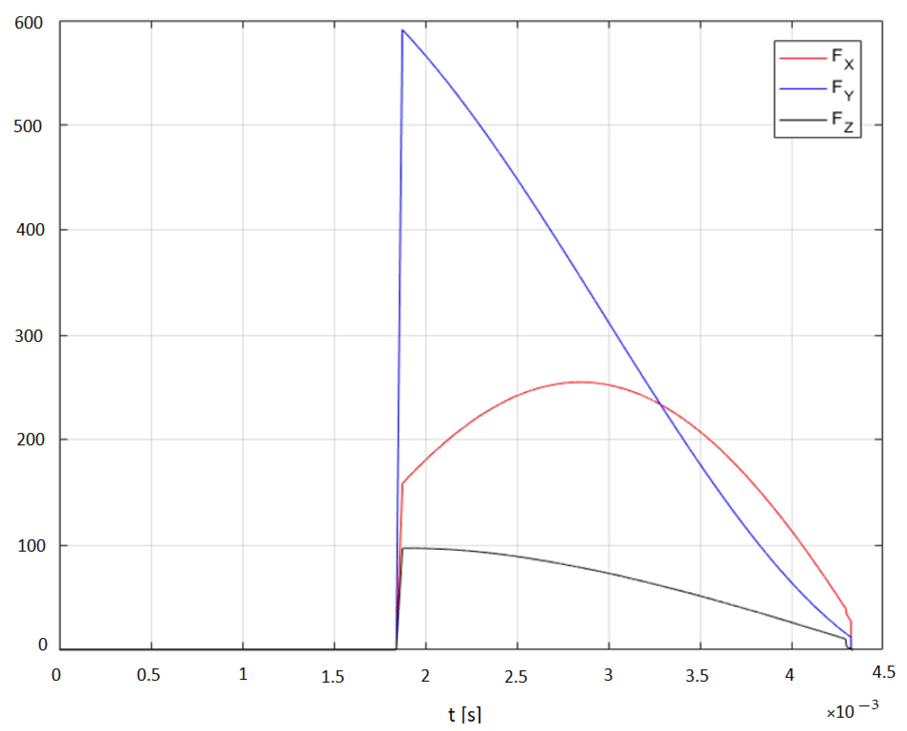
2.4. Cutting Forces
3. Results
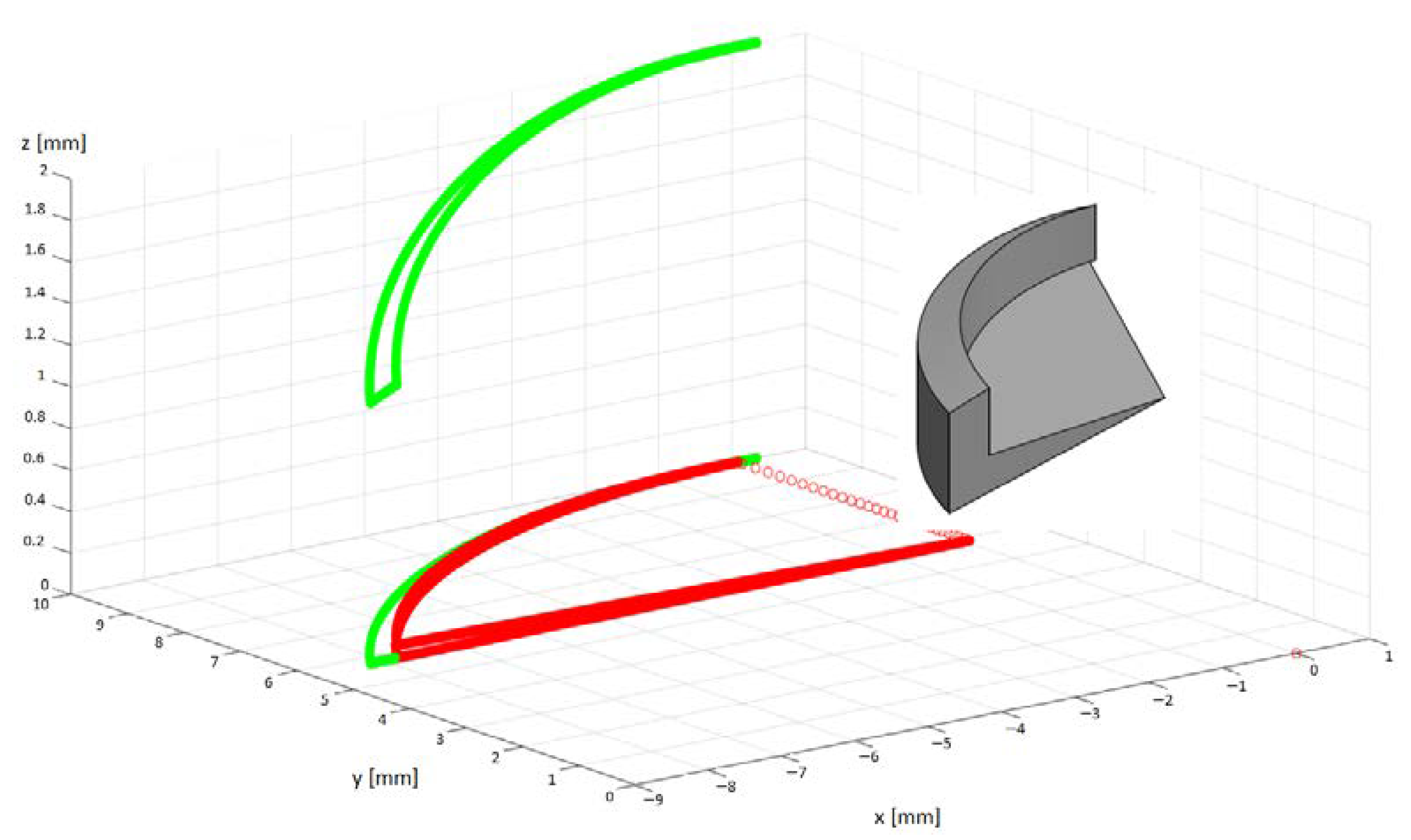
3.1. Uncut Chip Geometry Model
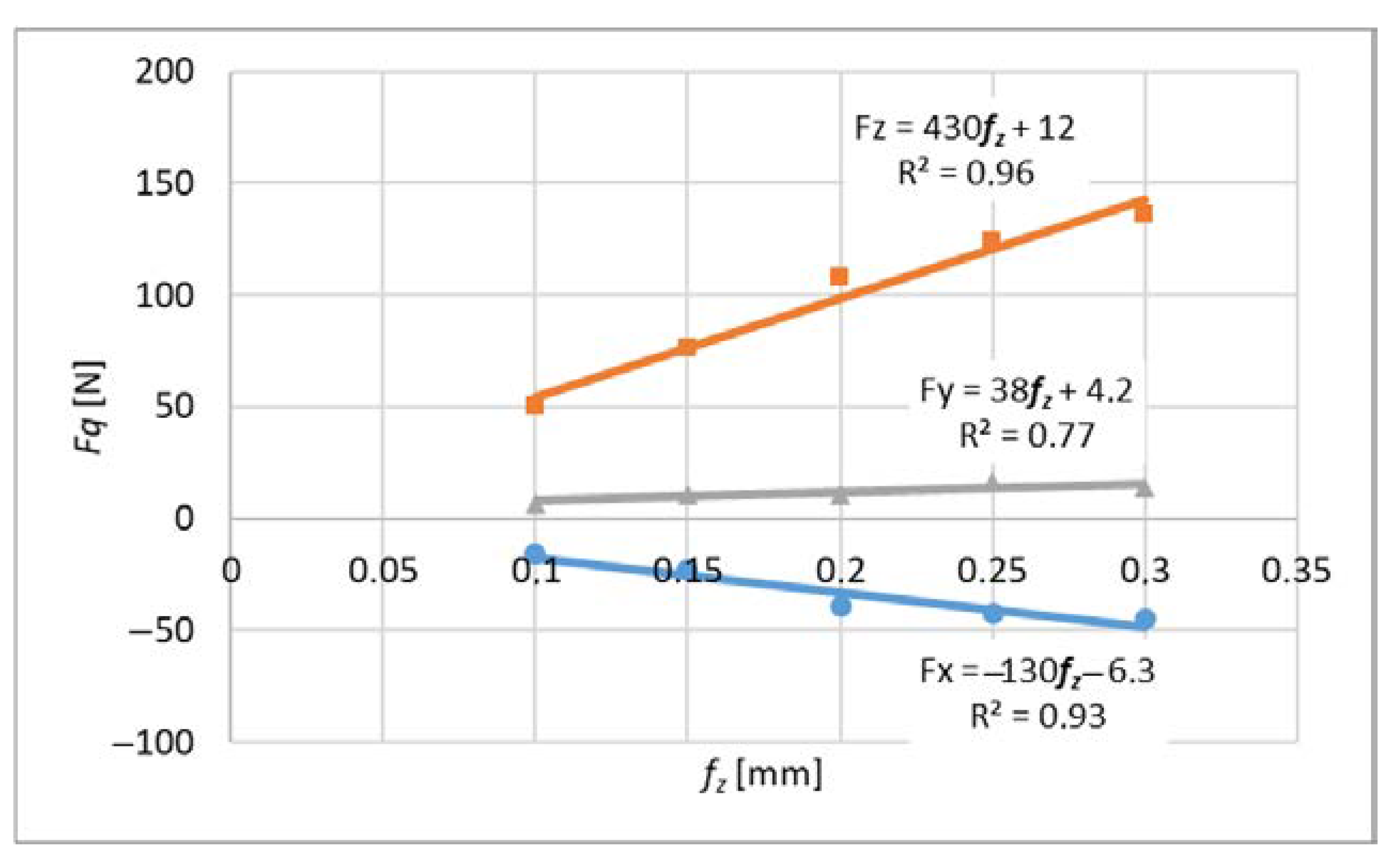
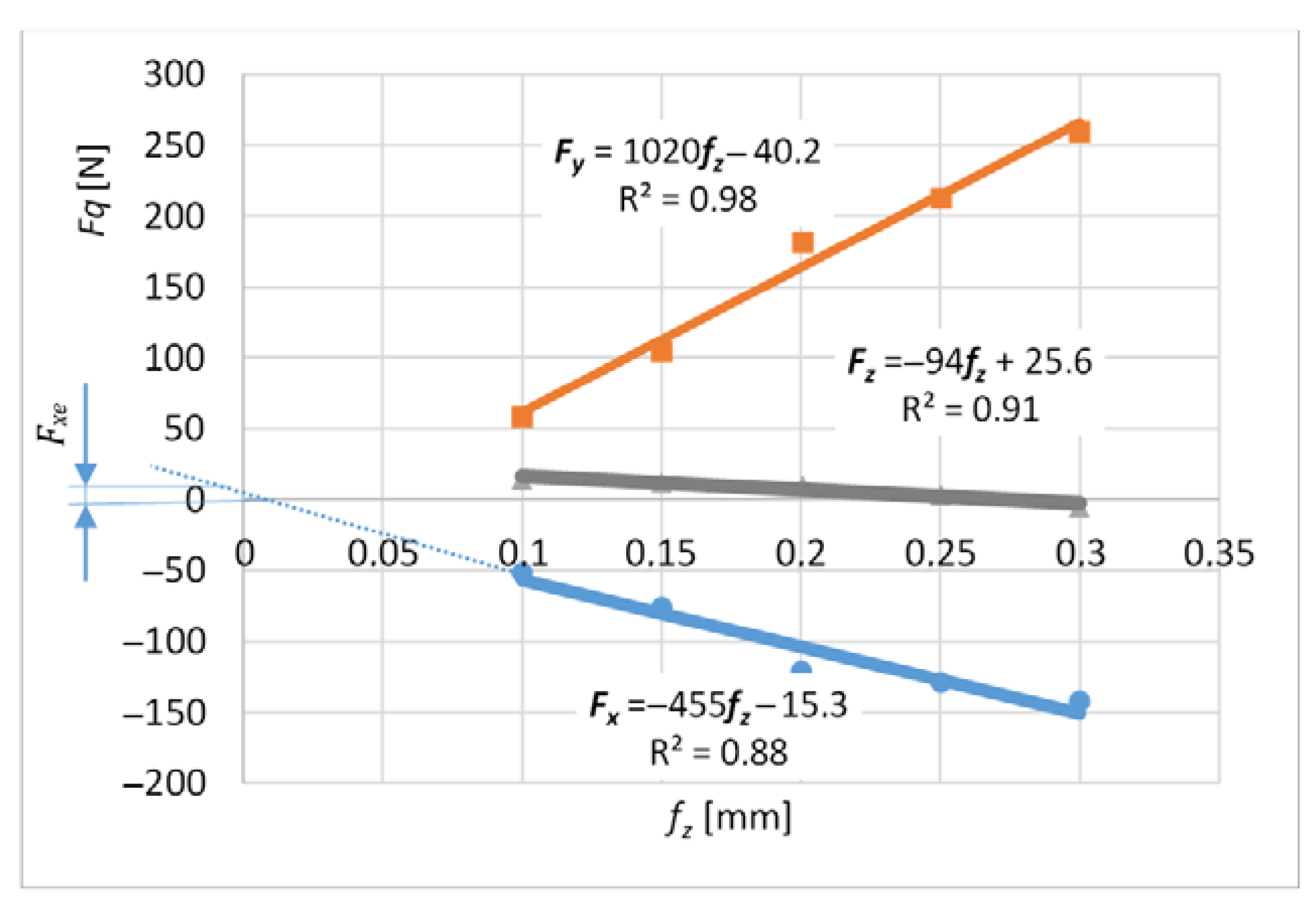
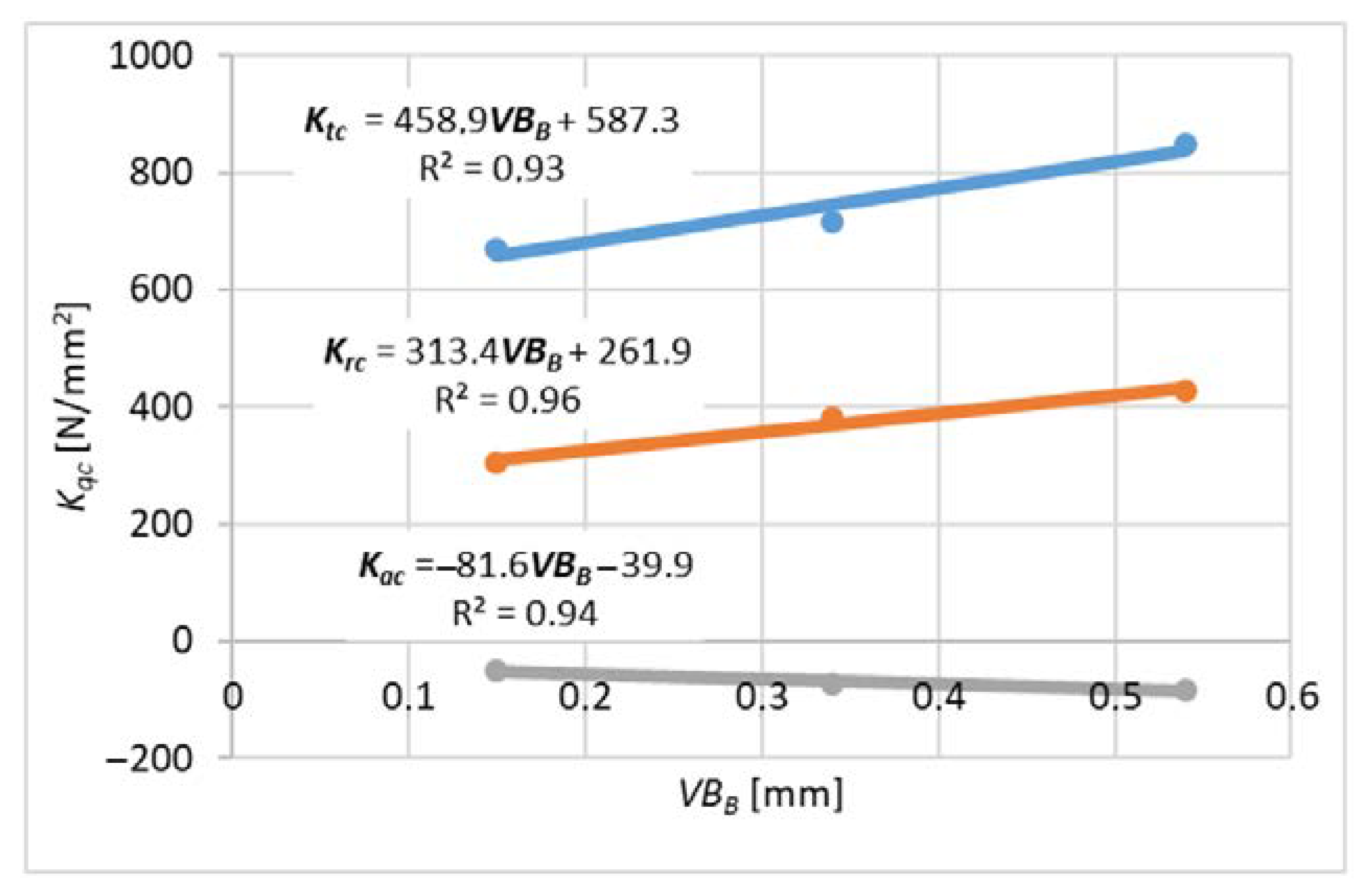
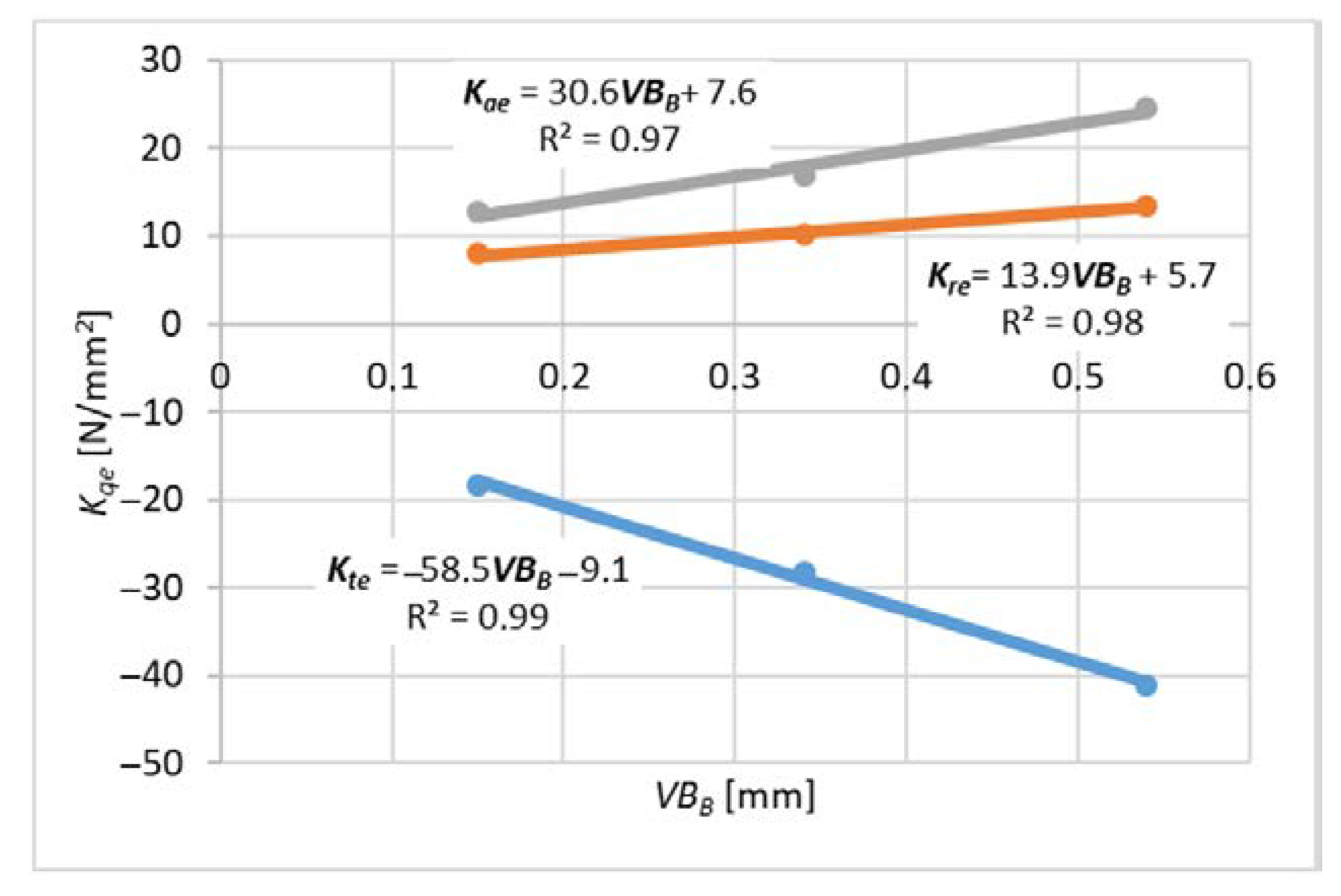
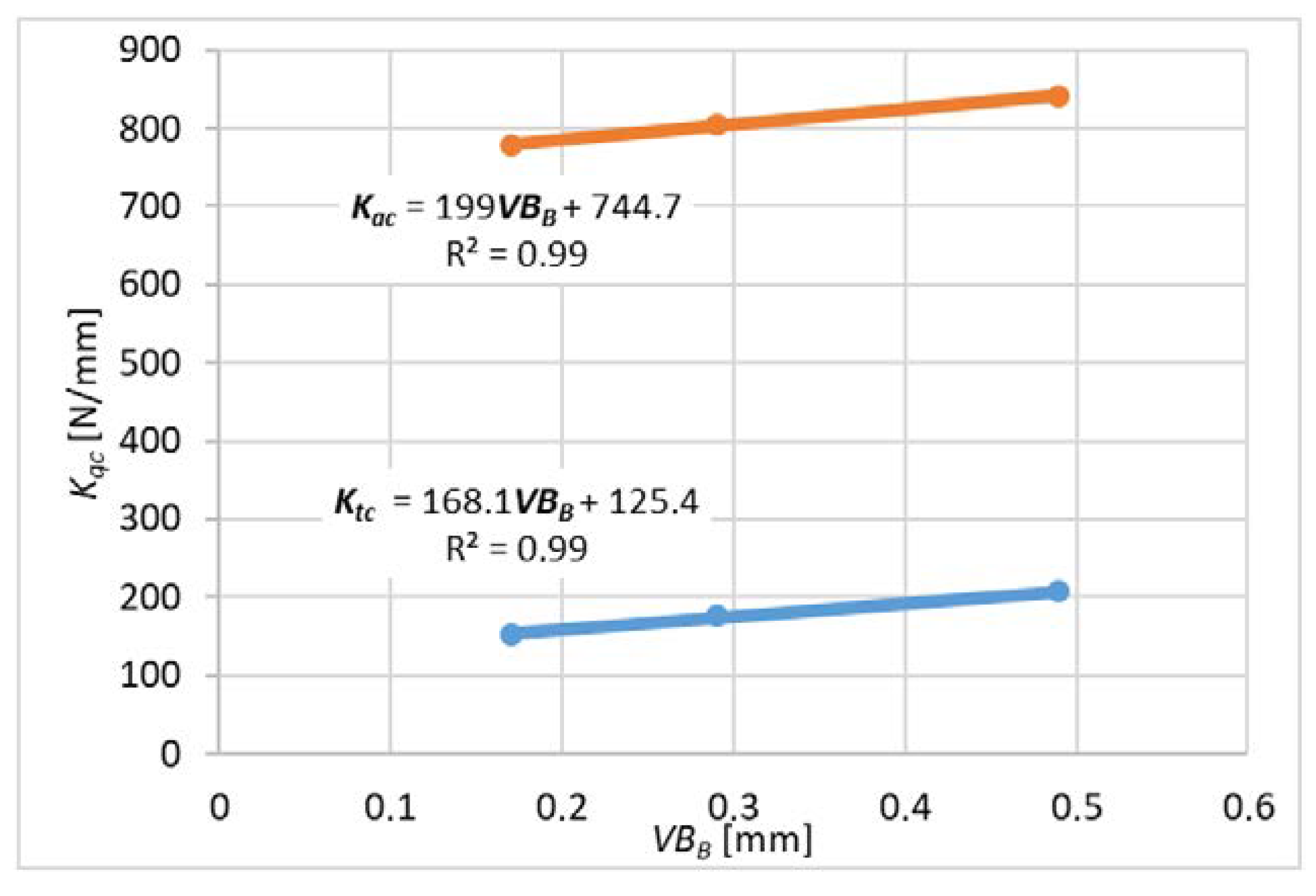
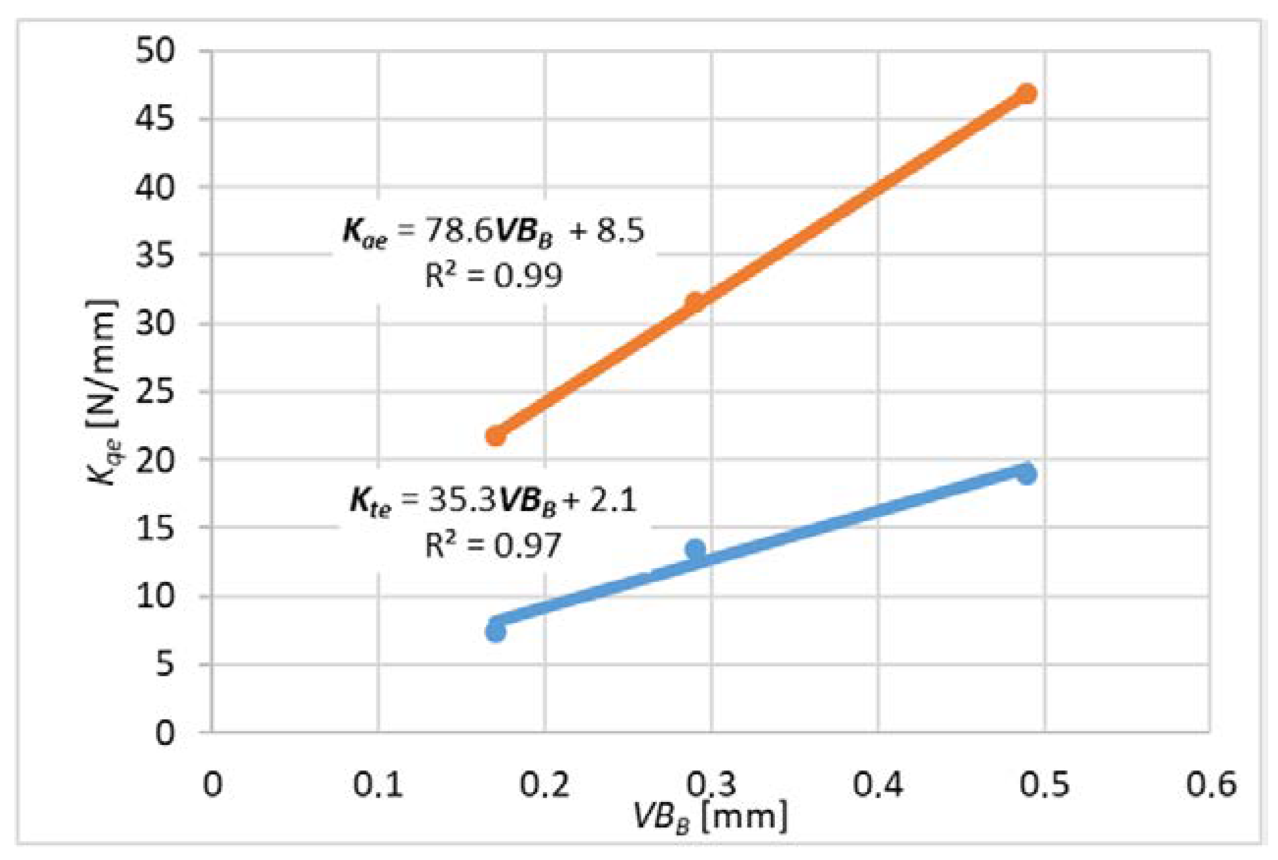
3.2. Cutting Forces Coefficions
- where q is x, y, z
- where Fqc is the slope of the linear function and Fqe is the constant value.
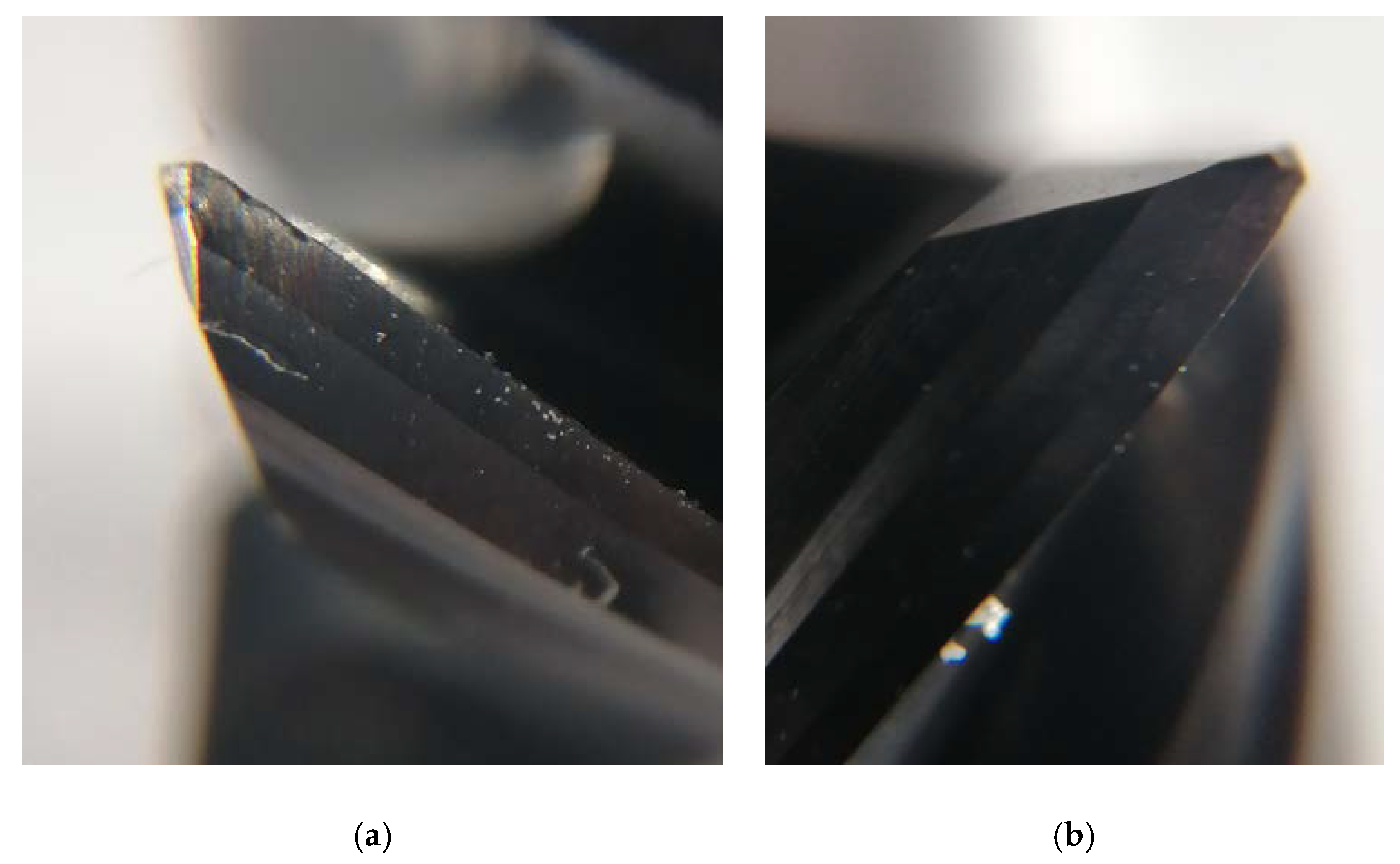
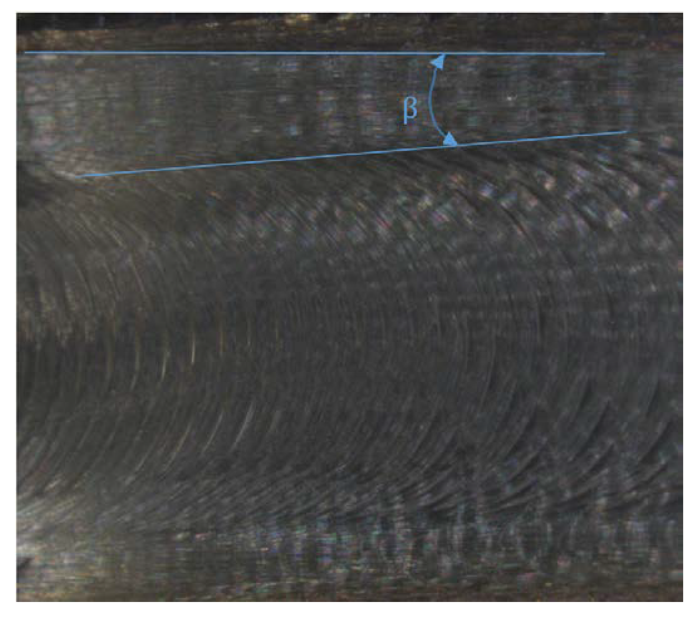
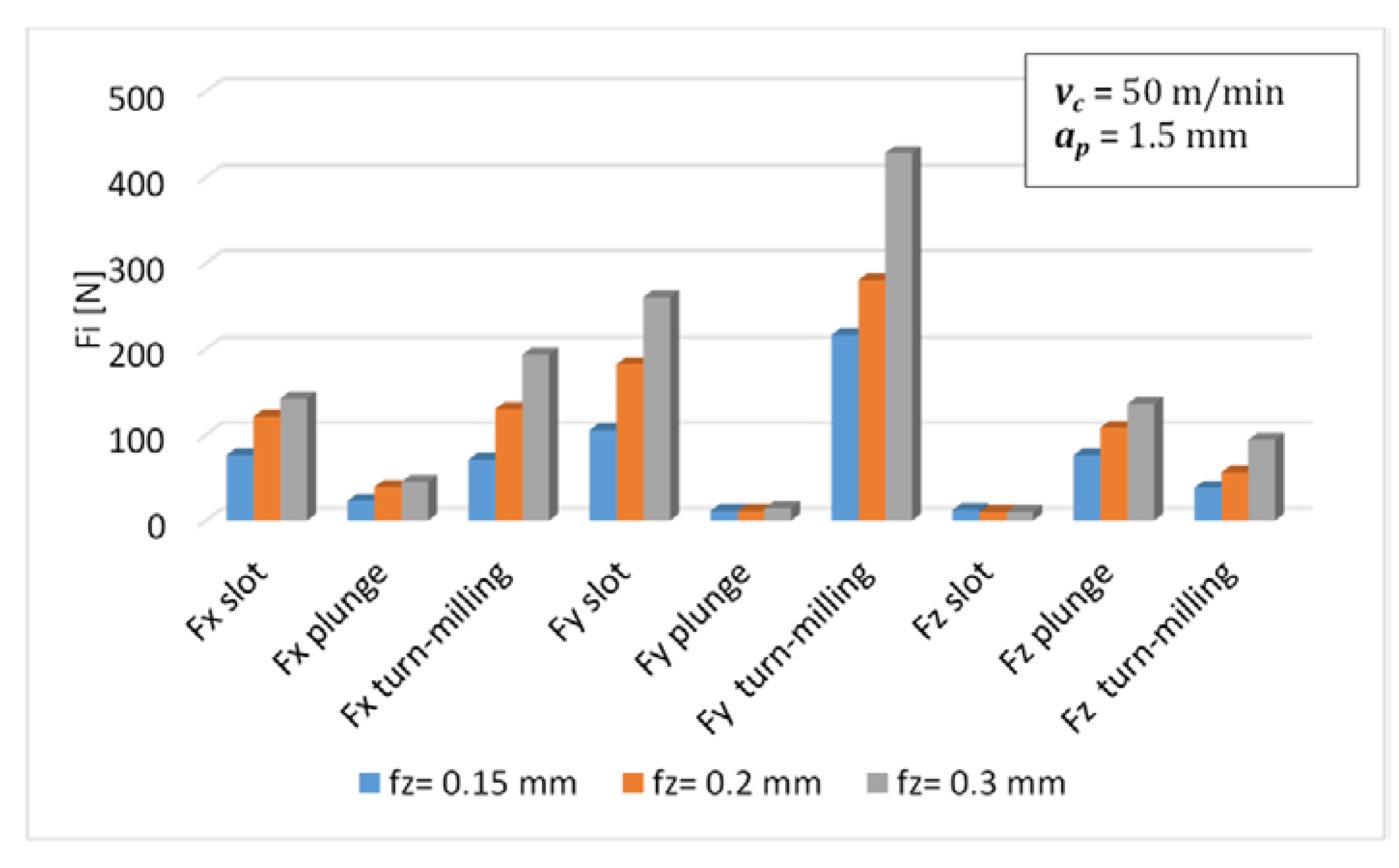
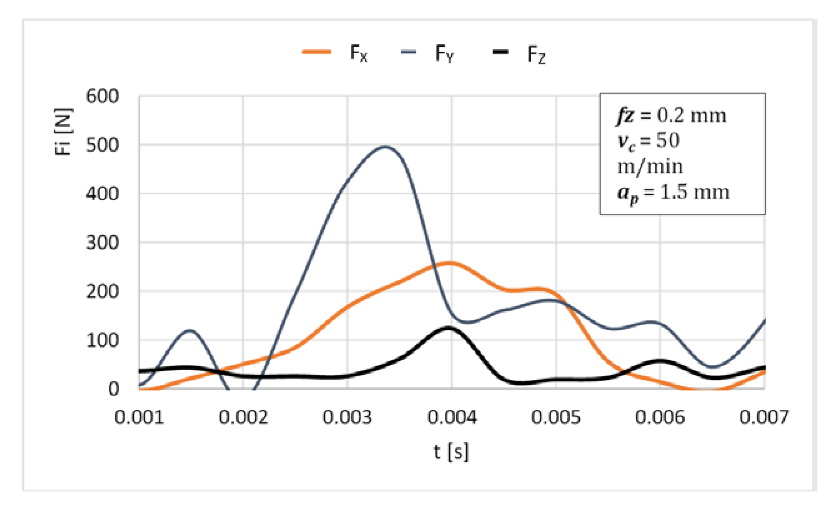
3.3. Research and Analysis for Turn-Milling
4. Conclusions
- The forces occurring during the turn-milling process are higher than in the case of conventional milling (with the same cutting parameters), which may lead to the tool damage during machining. This fact should be taken into account when selecting the process parameters. During the tur-milling process, it is not recommended to use a feed per tooth 0.3 mm. The smallest forces were obtained with a feed 0.15 mm.
- For the milling cutter used, the cutting force coefficients of the flank and end edge are different and therefore must be calibrated individually.
- The simulated results shows that under certain machining conditions, both the flank and leading edge contribute significantly to the total cutting forces.
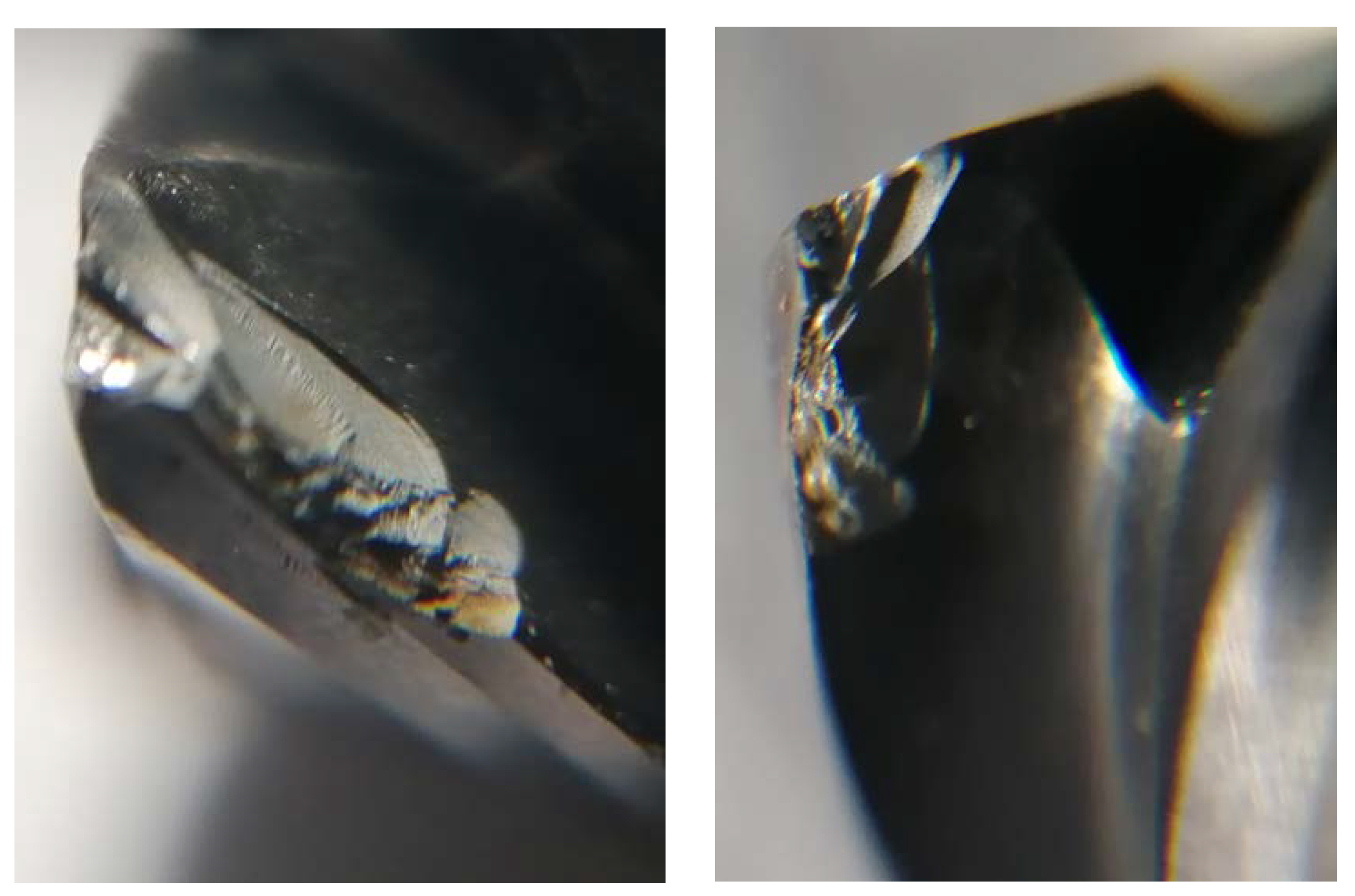
- Tool wear during machining has a significant impact on the values of the cutting force proportional coefficients. In the case of the tested material, it is important to take it into account when creating cutting force models.
Author Contributions
Funding
Institutional Review Board Statement
Informed Consent Statement
Data Availability Statement
Conflicts of Interest
References
- Pervaiz, S.; Kannan, S.; Subramaniam, A. Optimization of cutting process parameters in inclined drilling of inconel 718 using finite element method and taguchi analysis. Materials 2020, 13, 3995. [Google Scholar] [CrossRef] [PubMed]
- Wojciechowski, S.; Przestacki, D.; Chwalczuk, T. The evaluation of surface integrity during machining of inconel 718 with various laser assistance strategies. MATEC Web Conf. 2015, 136, 01006. [Google Scholar] [CrossRef] [Green Version]
- Grzesik, W.; Niesłony, P.; Habrat, W.; Sieniawski, J.; Laskowski, P. Investigation of tool wear in the turning of Inconel 718 superalloy in terms of process performance and productivity enhancement. Tribol. Int. 2018, 118, 337–346. [Google Scholar] [CrossRef]
- Karaguzel, U.; Olgun, U.; Uysal, E.; Buadak, E.; Bakkal, M. Increasing tool life in machining of difficult-to-cut materials using nonconventional turning processes. Int. J. Manuf. Technol. 2015, 77, 1993–2004. [Google Scholar] [CrossRef]
- Aspinwall, D.; Dewes, R.; Mantle, A. The machining of ɣ-TiAl intermetallic alloy. CIRP Ann.-Manuf. Technol. 2005, 54, 99–104. [Google Scholar] [CrossRef]
- Boozarpoor, M.; Teimouri, R.; Yazdani, K. Comprehensive study on effect of orthogonal turn-milling parameters on surface integrity of Inconel 718 considering production rate as constrain. Int. J. Lightweight Mater. Manuf. 2021, 4, 145–155. [Google Scholar] [CrossRef]
- Karagüzel, U.; Uysal, E.; Budak, E.; Bakkal, M. Analytical modeling of turn-milling process geometry, kinematics and mechanics. Int. J. Mach. Tools Manuf. 2015, 91, 24–33. [Google Scholar] [CrossRef]
- Neagu, C.; Gheorghe, M.; Dumitrescu, A. Fundamentals on Face Milling Processing of Straight Shafts. J. Mater. Process. Technol. 2005, 166, 337–344. [Google Scholar] [CrossRef]
- Shichiri, S.; Utsumi, K.; Sasahara, H. Effect of tool posture for tool wear on turn-milling. In Proceedings of the 2018 ISFA-2018 International Symposium on Flexible Automation; The Institute of Systems, Control and Information Engineers: Kyoto, Japan, 2018; pp. 43–46. [Google Scholar]
- Jin, C.-Z.; Jia, C.-D.; Pang, S.-Q. Wearing mechanism of tools in the orthogonal turn-milling of high strength steel. Binggong Xuebao/Acta Armamentarii 2005, 26, 397–400. [Google Scholar]
- Karaguzel, U.; Bakkal, M.; Budak, E. Mechanical and Thermal Modeling of Orthogonal Turn-milling Operation. Procedia CIRP 2017, 58, 287–292. [Google Scholar] [CrossRef]
- Qiu, W.; Liu, Q.; Ding, J.; Yuan, S. Cutting force prediction in orthogonal turn-milling by directly using engagement boundaries. Int. J. Adv. Manuf. Technol. 2016, 86, 963–975. [Google Scholar] [CrossRef]
- Qiu, W.; Liu, Q.; Yuan, S. Modeling of cutting forces in orthogonal turn-milling with round insert cutters. Int. J. Adv. Manuf. Technol. 2015, 78, 1211–1222. [Google Scholar] [CrossRef]
- Otalora-Ortega, H.; Osoro, P.A.; Arrazola Arriola, P.J. Analytical modeling of the uncut chip geometry to predict cutting forces in orthogonal centric turn-milling operations. Int. J. Mach. Tools Manuf. 2019, 144, 103428. [Google Scholar] [CrossRef]
- Otalora-Ortega, H.; Aristimuño Osoro, P.; Arrazola Arriola, P. Uncut chip geometry determination for cutting forces prediction in orthogonal turn-milling operations considering the tool profile and eccentricity. Int. J. Mech. Sci. 2021, 198, 106351. [Google Scholar] [CrossRef]
- Altintas, Y. Manufacturing Automation: Manufacturing Automation: Metal Cutting Mechanics, Machine Tool Vibrations, and CNC Design; Cambridge University Press: New York, NY, USA, 2012; pp. 38–47. [Google Scholar]


| Ni | Cr | Nb | Mo | Ti | Al | Co | Si | |
|---|---|---|---|---|---|---|---|---|
| Min.% | 50 | 17 | 4.75 | 2.8 | 0.65 | 0.2 | - | - |
| Max.% | 55 | 21 | 5.50 | 3.30 | 1.15 | 0.80 | 1.00 | 0.35 |
| Mn | Cu | C | P | S | B | Fe | ||
| Min.% | - | - | - | - | - | - | - | |
| Max.% | 0.35 | 0.30 | 0.08 | 0.015 | 0.015 | 0.006 | balance |
| lp. | vc [m/min] | ap [mm]/ae [mm] | fz [mm] |
|---|---|---|---|
| 1. | 50 | 1.5 | 0.1 |
| 2. | 50 | 1.5 | 0.15 |
| 3. | 50 | 1.5 | 0.2 |
| 4. | 50 | 1.5 | 0.25 |
| 5. | 50 | 1.5 | 0.3 |
Publisher’s Note: MDPI stays neutral with regard to jurisdictional claims in published maps and institutional affiliations. |
© 2021 by the authors. Licensee MDPI, Basel, Switzerland. This article is an open access article distributed under the terms and conditions of the Creative Commons Attribution (CC BY) license (https://creativecommons.org/licenses/by/4.0/).
Share and Cite
Felusiak-Czyryca, A.; Madajewski, M.; Twardowski, P.; Wiciak-Pikuła, M. Cutting Forces during Inconel 718 Orthogonal Turn-Milling. Materials 2021, 14, 6152. https://doi.org/10.3390/ma14206152
Felusiak-Czyryca A, Madajewski M, Twardowski P, Wiciak-Pikuła M. Cutting Forces during Inconel 718 Orthogonal Turn-Milling. Materials. 2021; 14(20):6152. https://doi.org/10.3390/ma14206152
Chicago/Turabian StyleFelusiak-Czyryca, Agata, Marek Madajewski, Paweł Twardowski, and Martyna Wiciak-Pikuła. 2021. "Cutting Forces during Inconel 718 Orthogonal Turn-Milling" Materials 14, no. 20: 6152. https://doi.org/10.3390/ma14206152
APA StyleFelusiak-Czyryca, A., Madajewski, M., Twardowski, P., & Wiciak-Pikuła, M. (2021). Cutting Forces during Inconel 718 Orthogonal Turn-Milling. Materials, 14(20), 6152. https://doi.org/10.3390/ma14206152