
Study on Microstructure and Mechanical Properties of Laser Welded Dissimilar Joint of P91 Steel and INCOLOY 800HT Nickel Alloy


Abstract
:1. Introduction
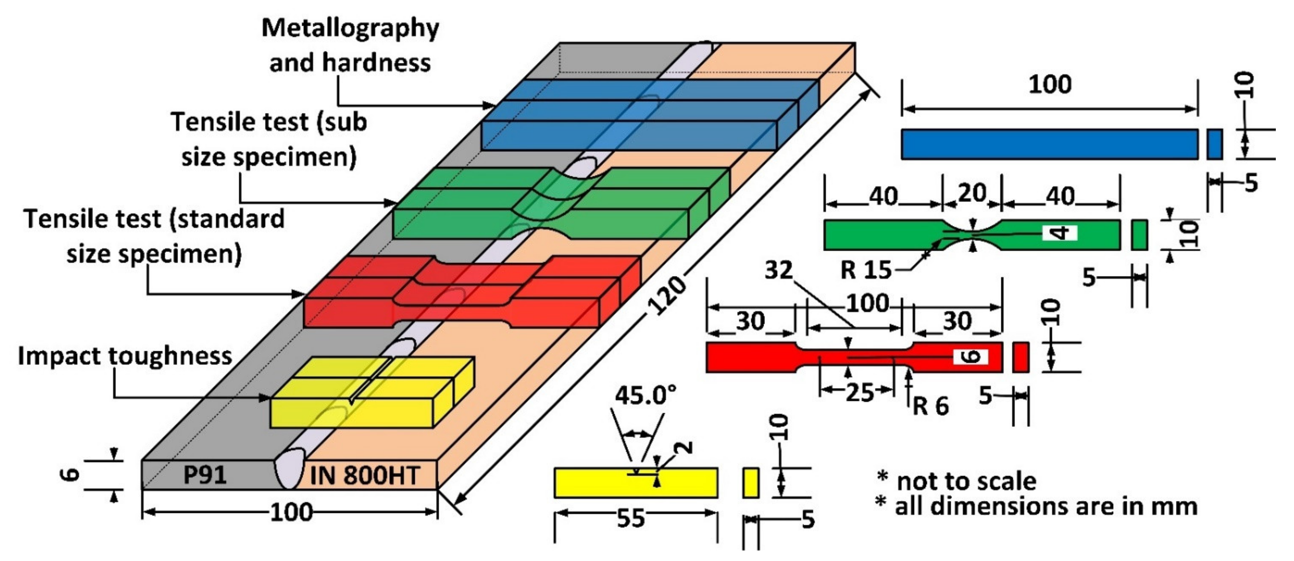
2. Materials and Methods
3. Results and Discussion
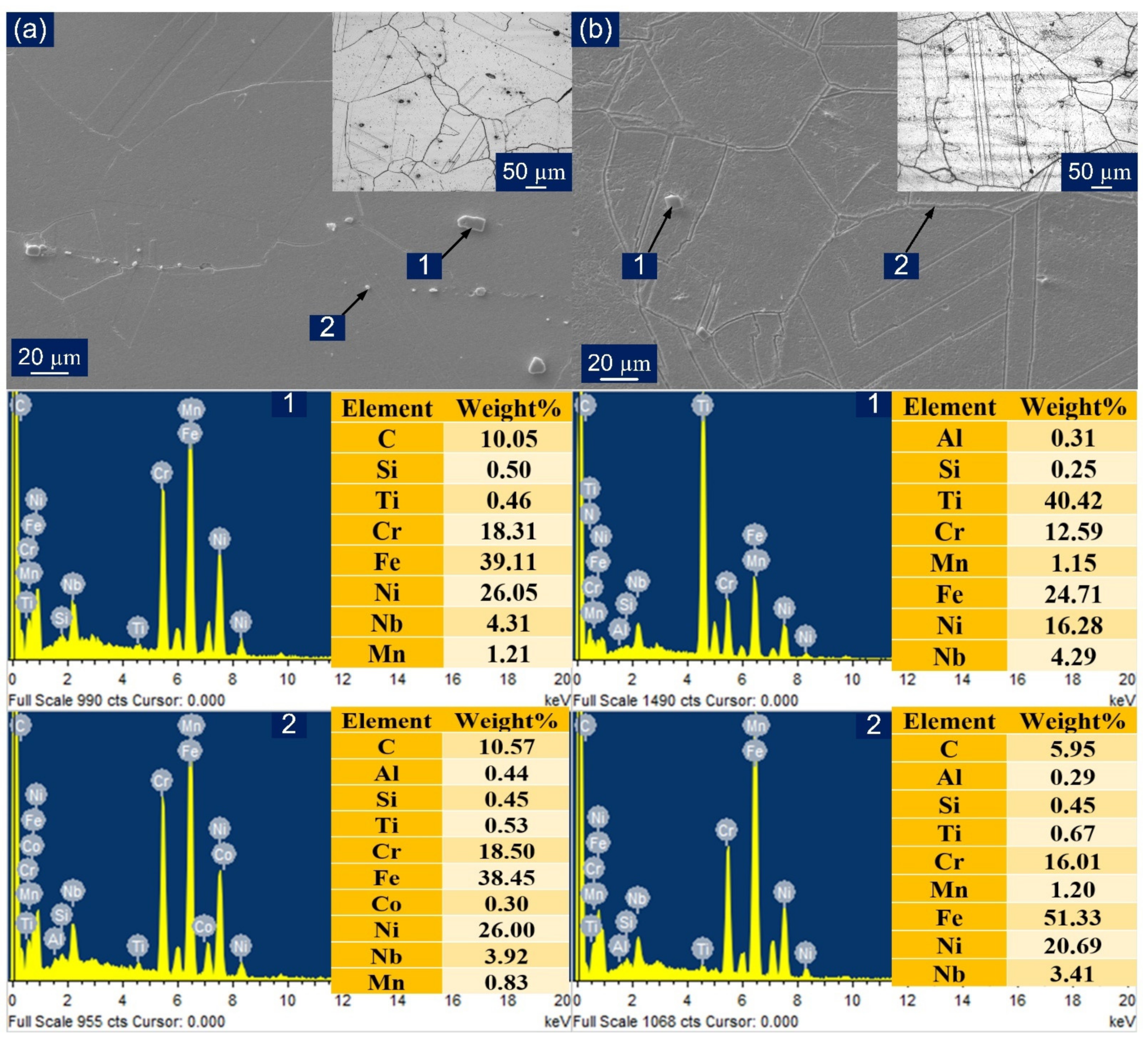
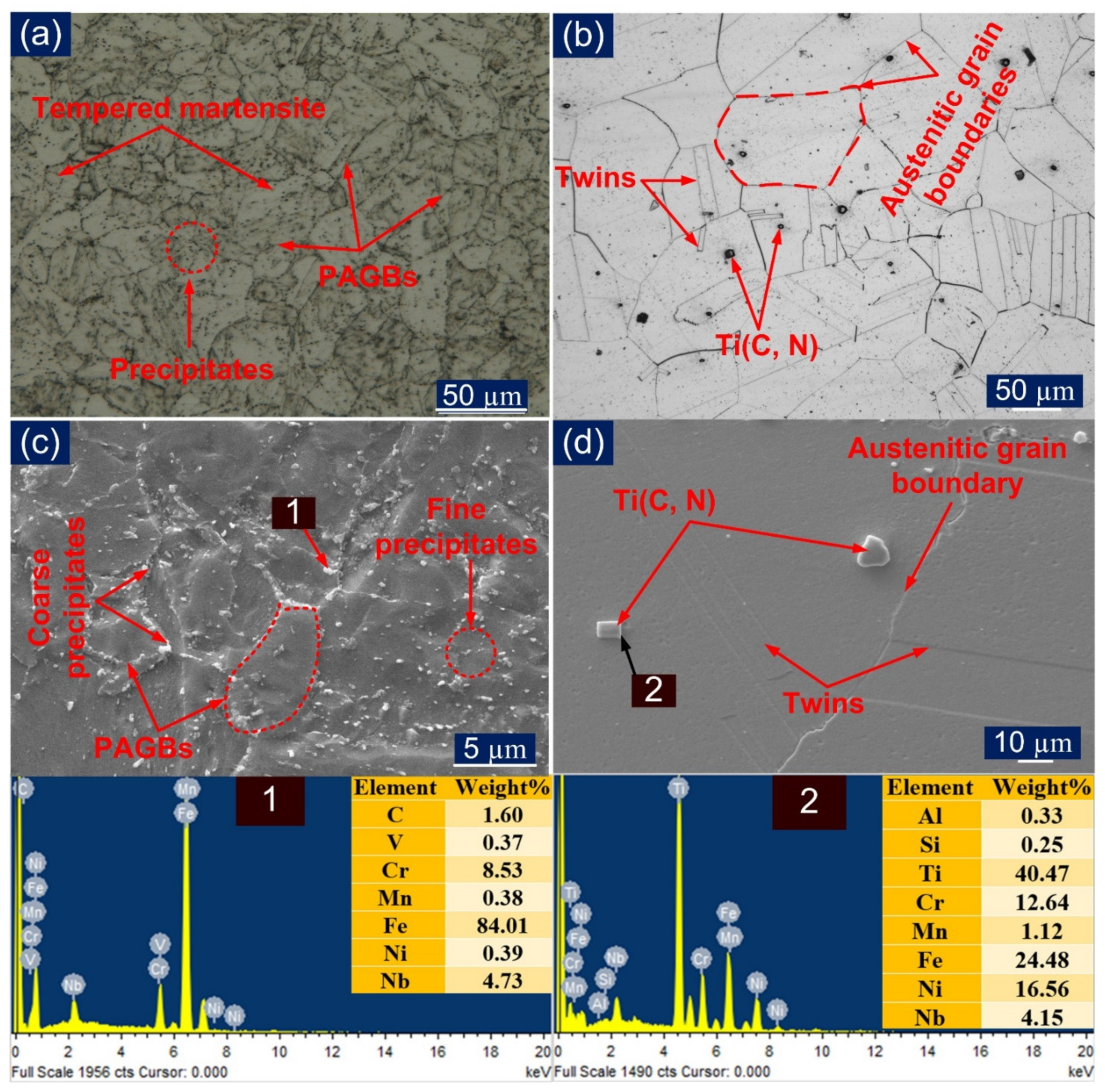
3.1. As-Received Material Microstructure
3.2. Characterization of the Weldments in As-Welded (AW) and Post-Weld Heat Treatment (PWHT) Condition
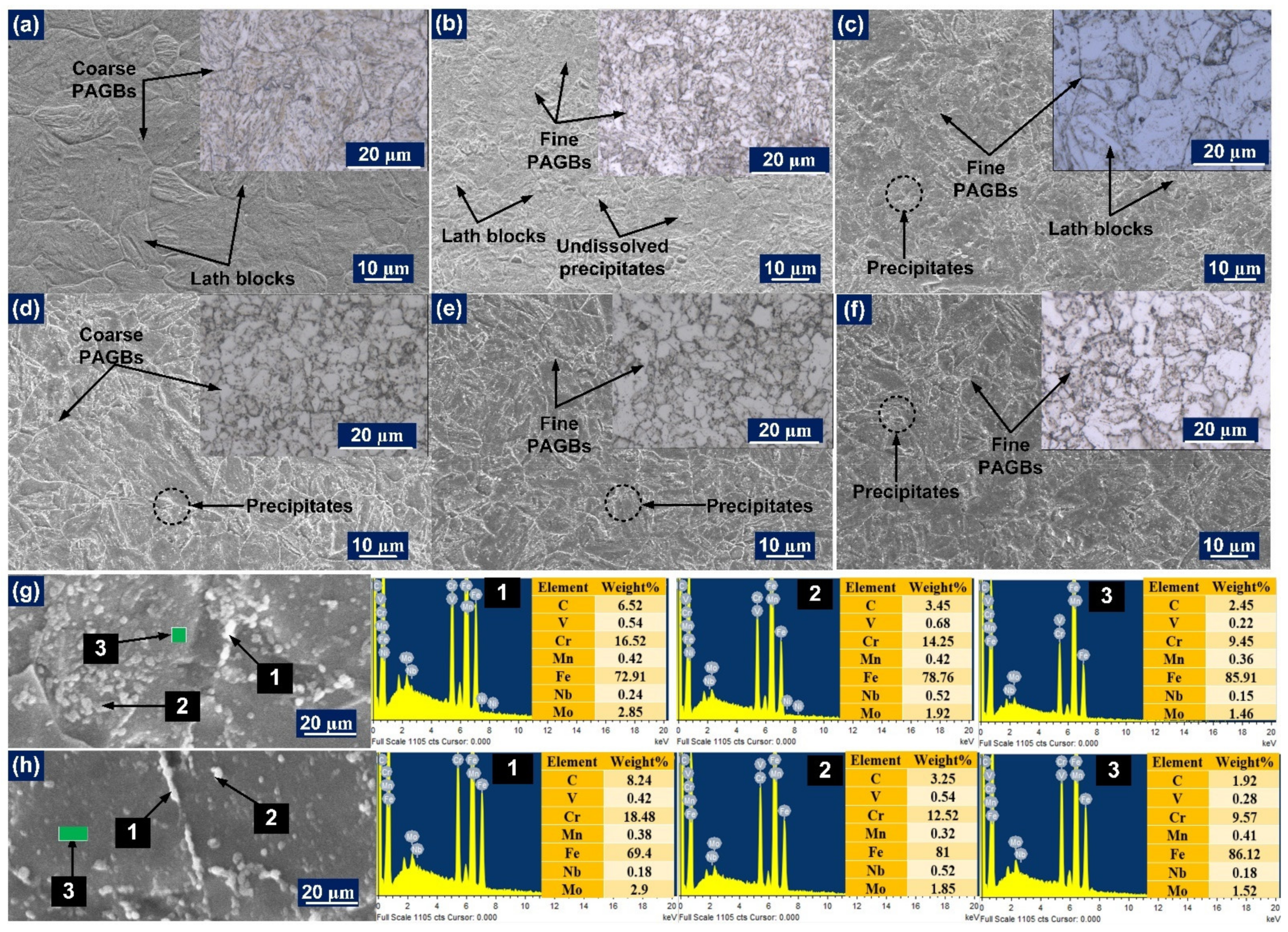
3.2.1. Heat-Affected Zones
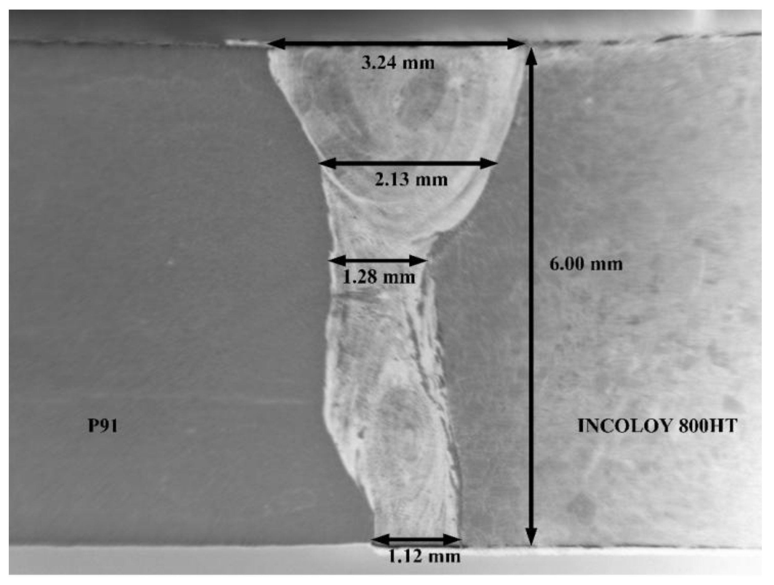
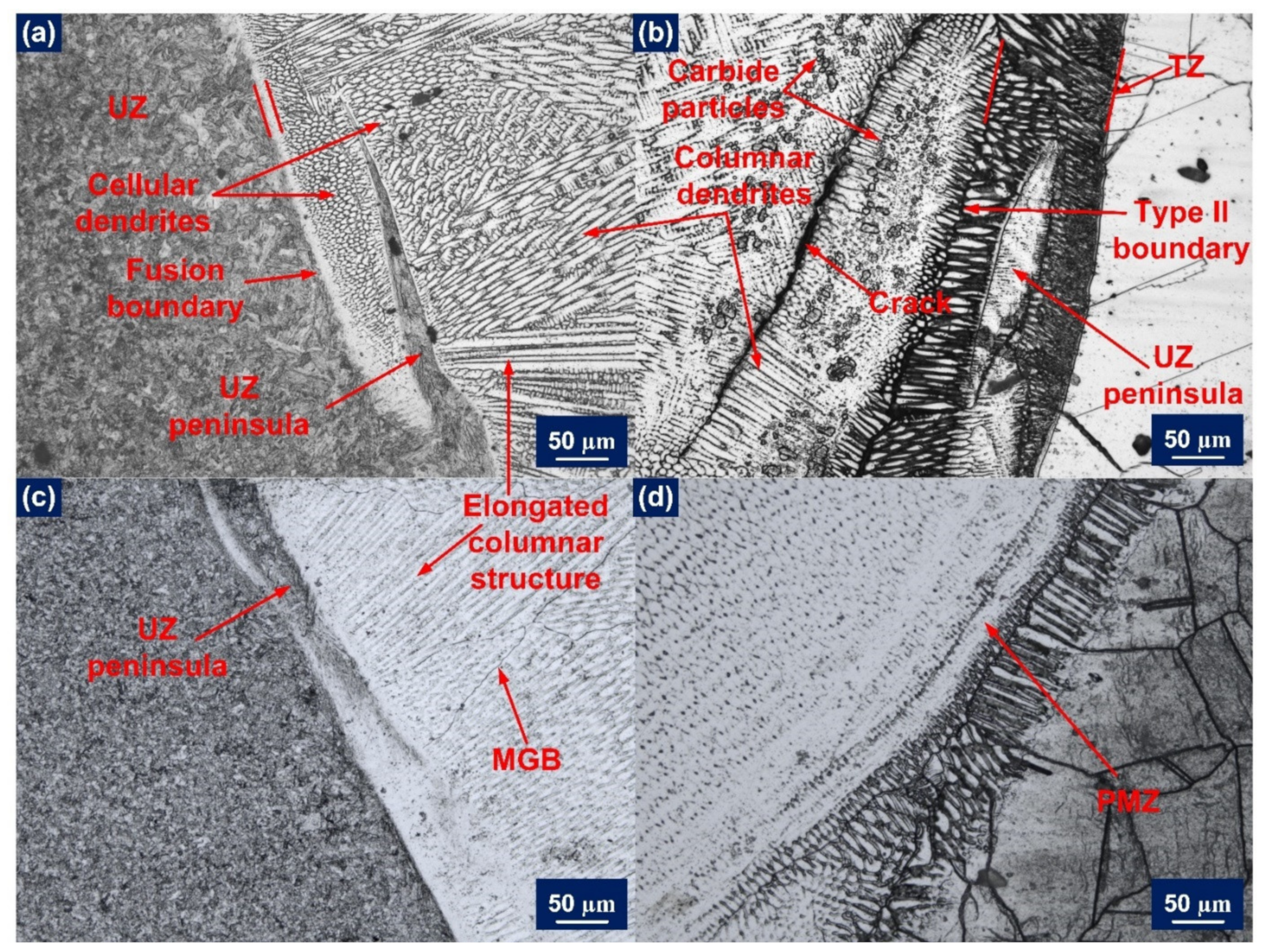
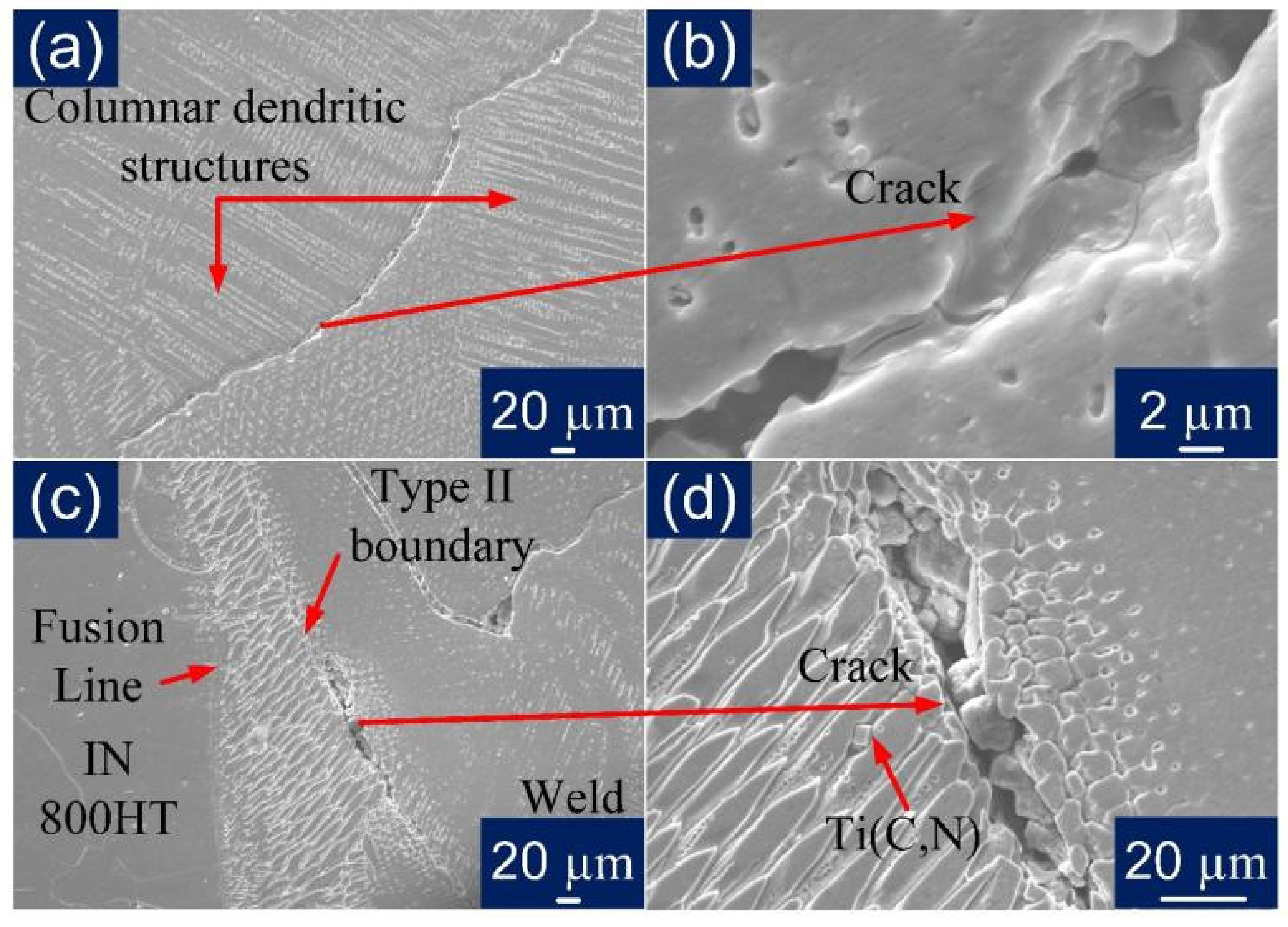
3.2.2. Weld Fusion Boundary
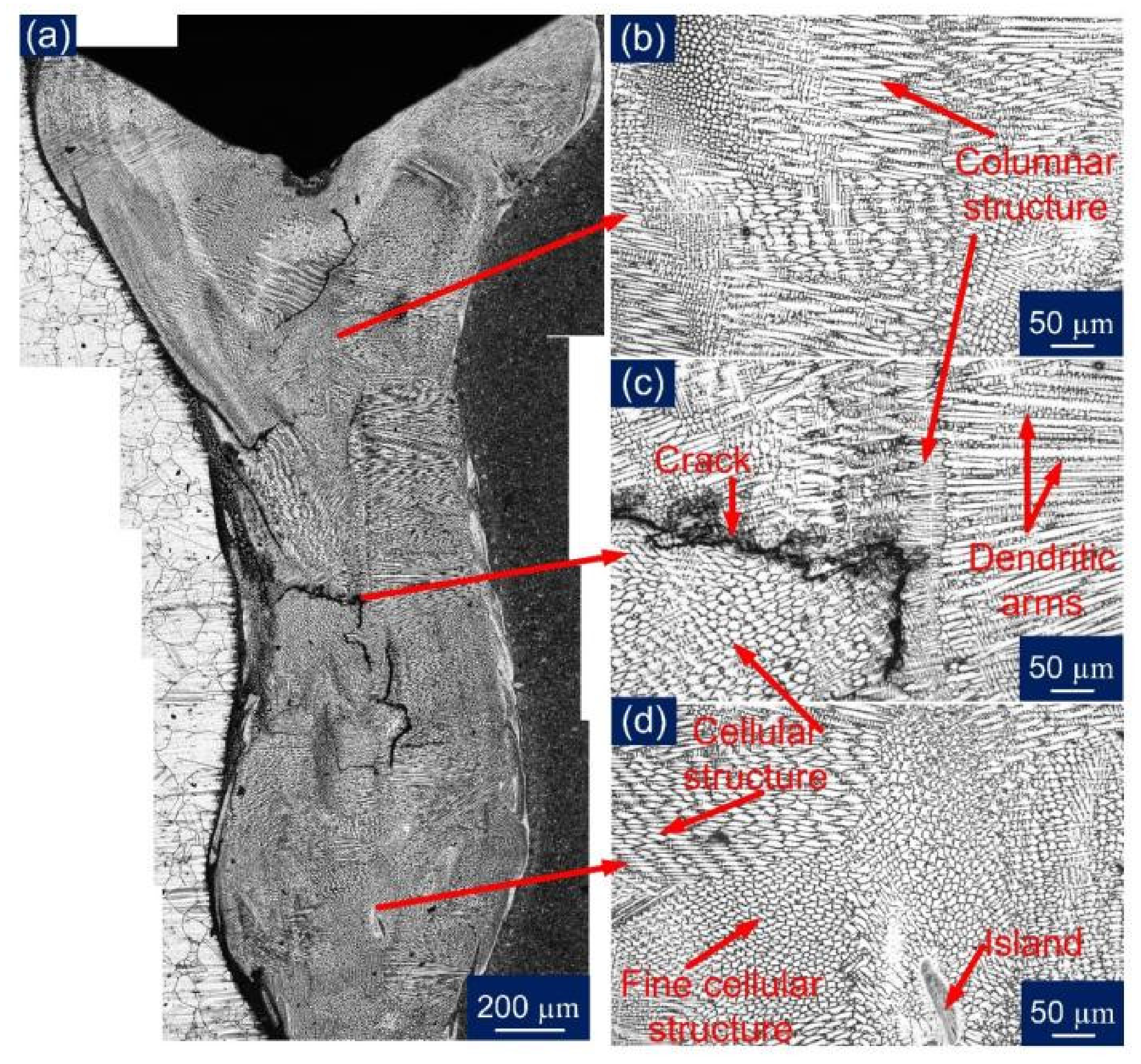
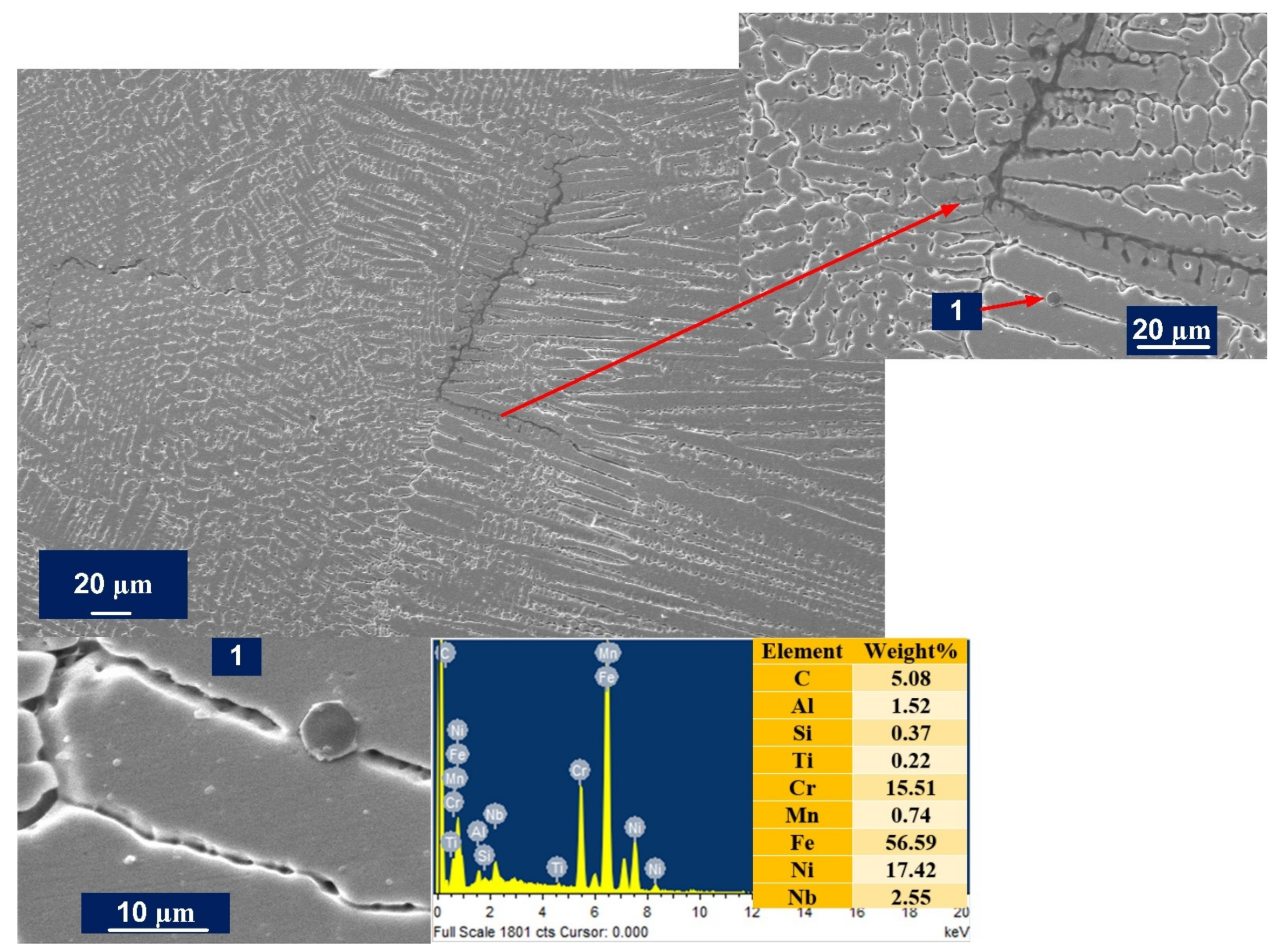
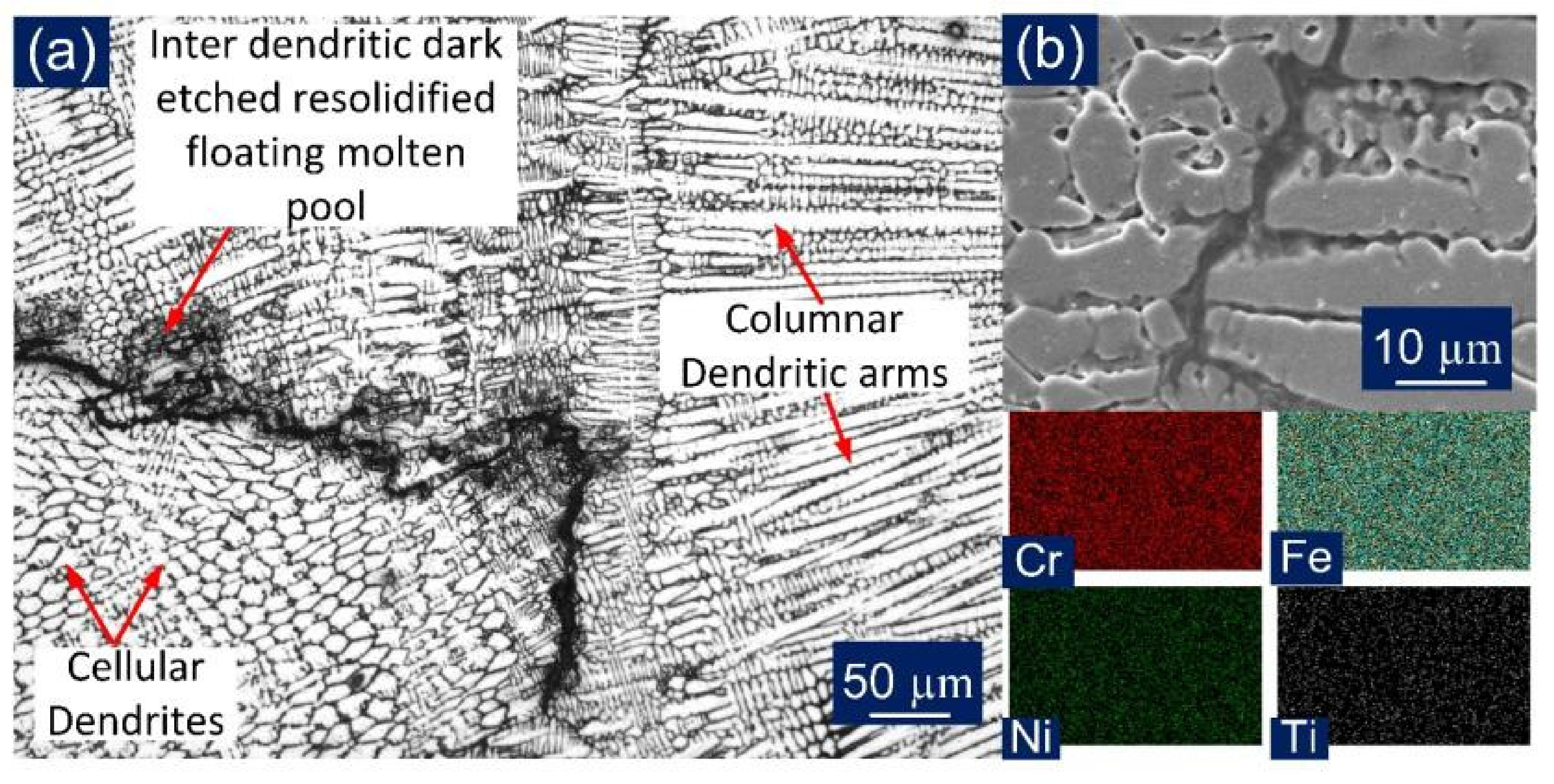
3.2.3. Weld Fusion Zone (WFZ)
3.3. Mechanical Properties of the Welded Joint
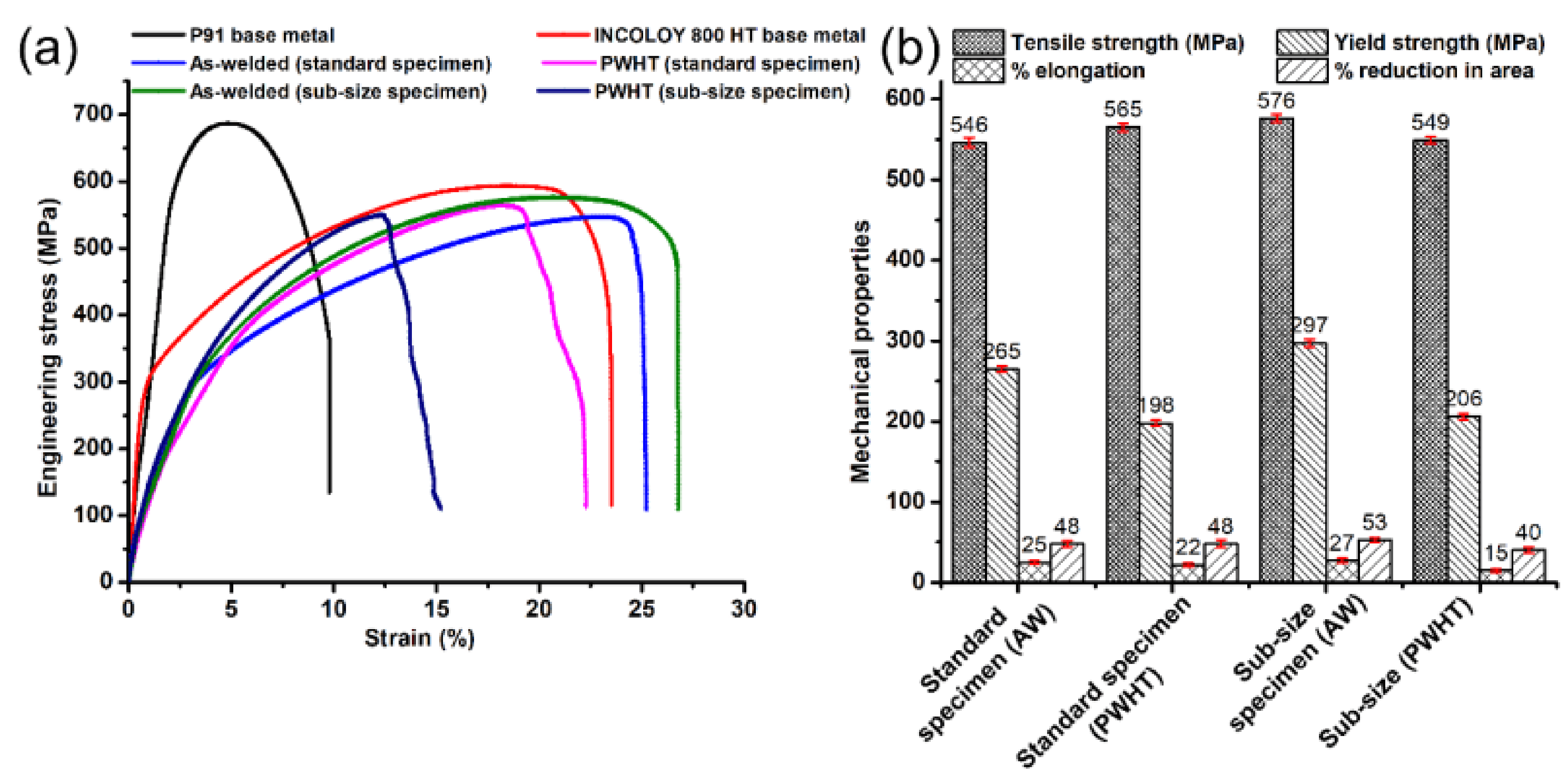
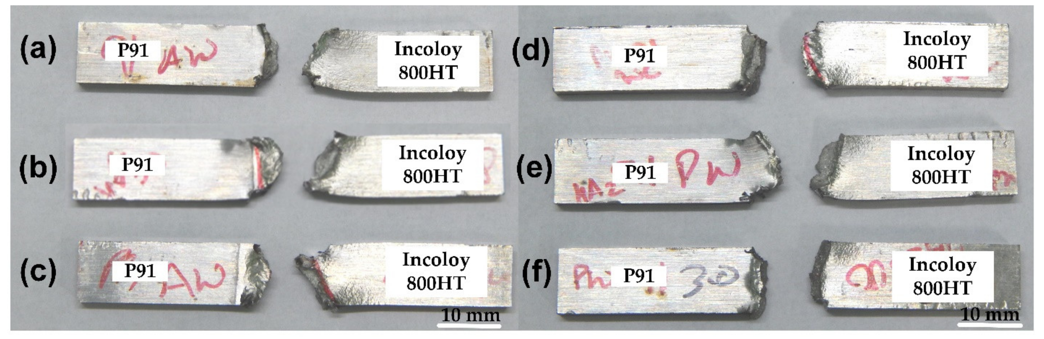
3.3.1. Tensile Properties
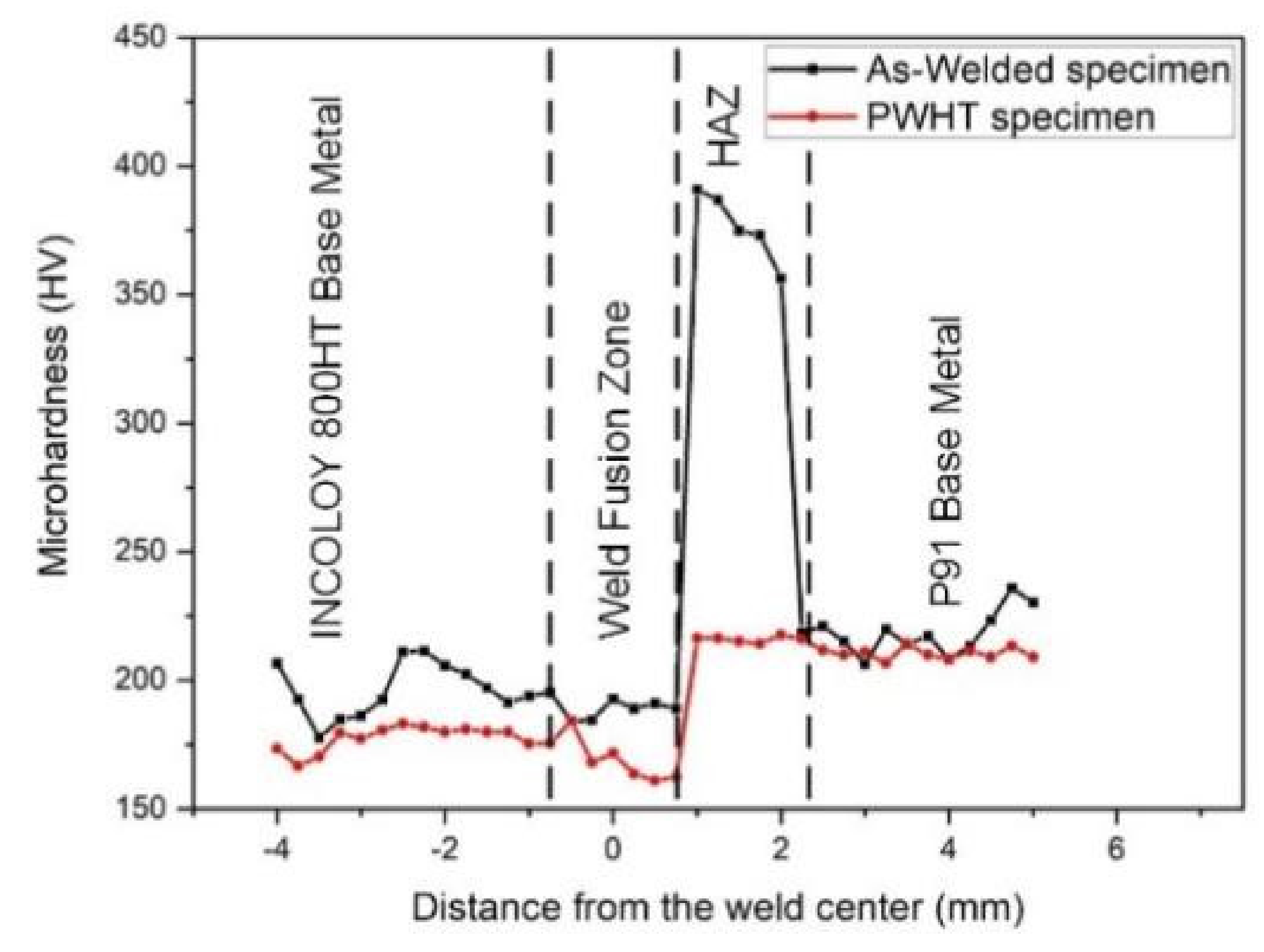
3.3.2. Microhardness Variation
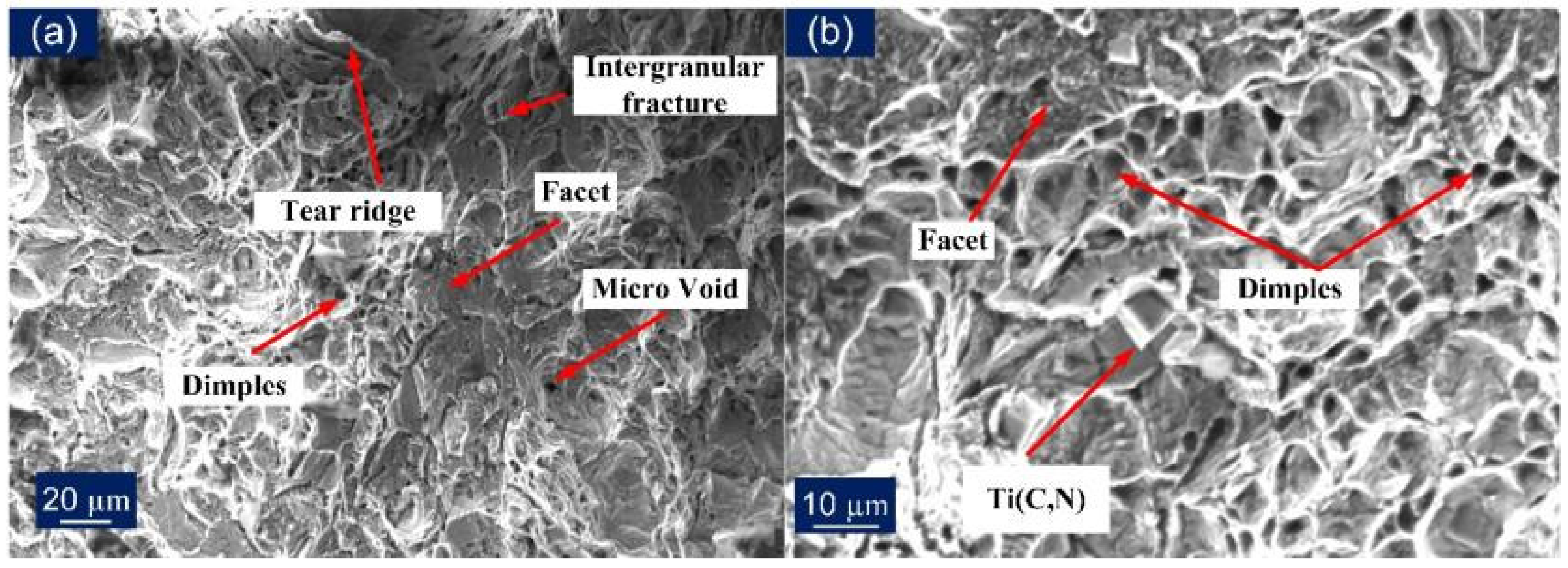
3.3.3. Charpy Impact Toughness
4. Conclusions
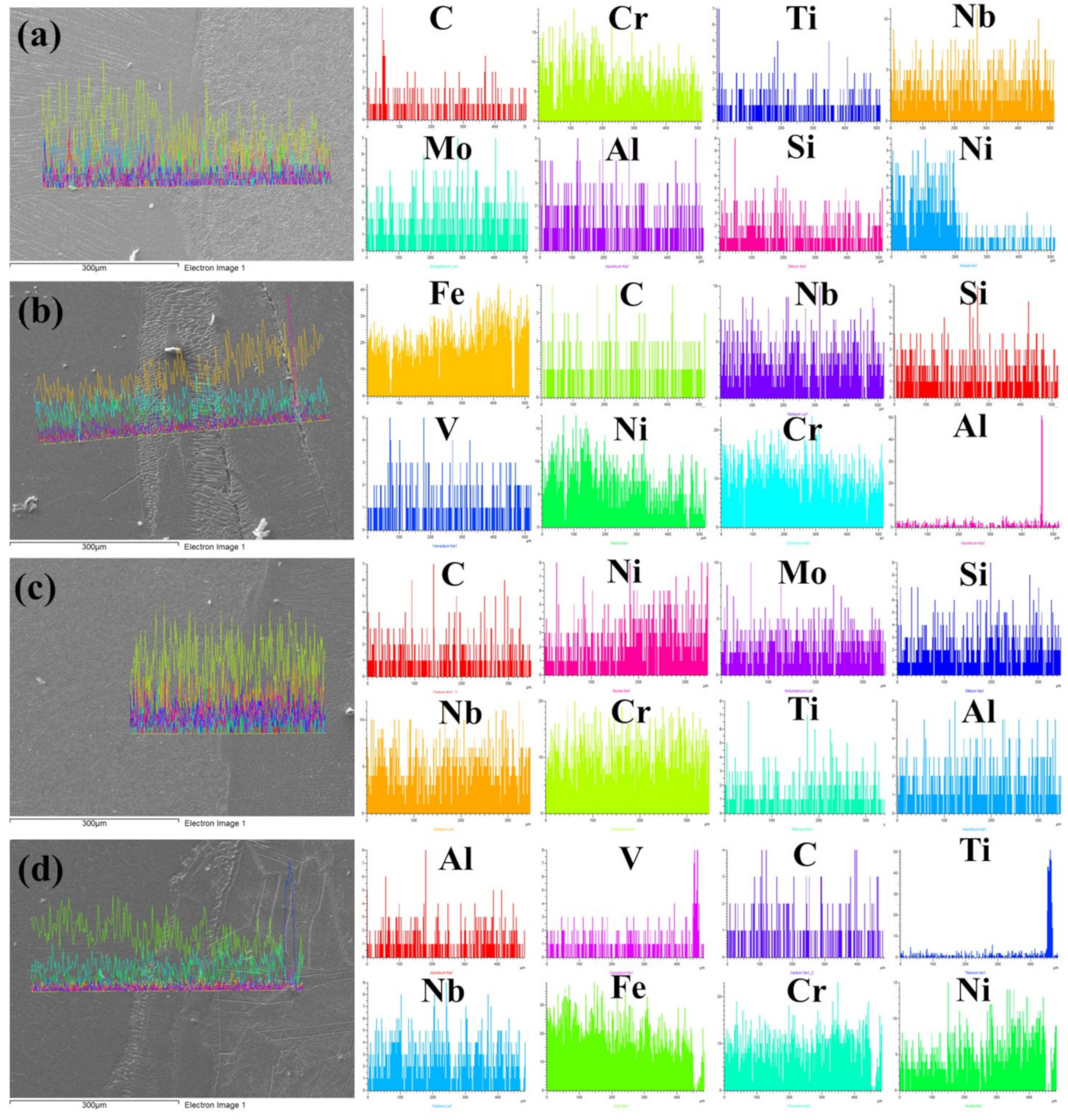
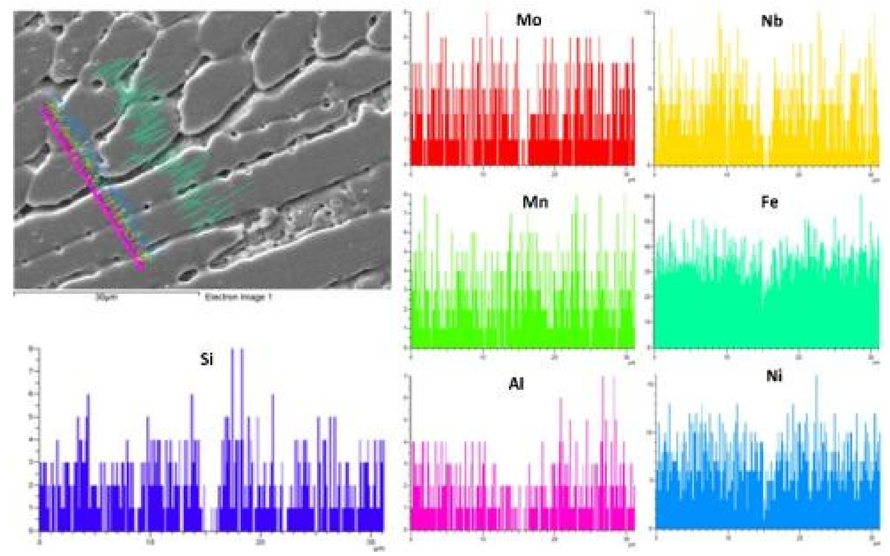
- The significant finding was of solidification cracks occurring in the weld zone only, due to high heat input from laser welding and invariable cooling due to the presence of dissimilar alloys. The solidification temperature difference due to the keyhole effect can account for the cracking that was observed in the weld fusion zone. The segregation of elements, such as Ti, Si, and Nb, was observed in inter-dendritic regions, which caused cracking along solidification boundaries. In addition, the formation of columnar dendritic structures contributes to cracking.
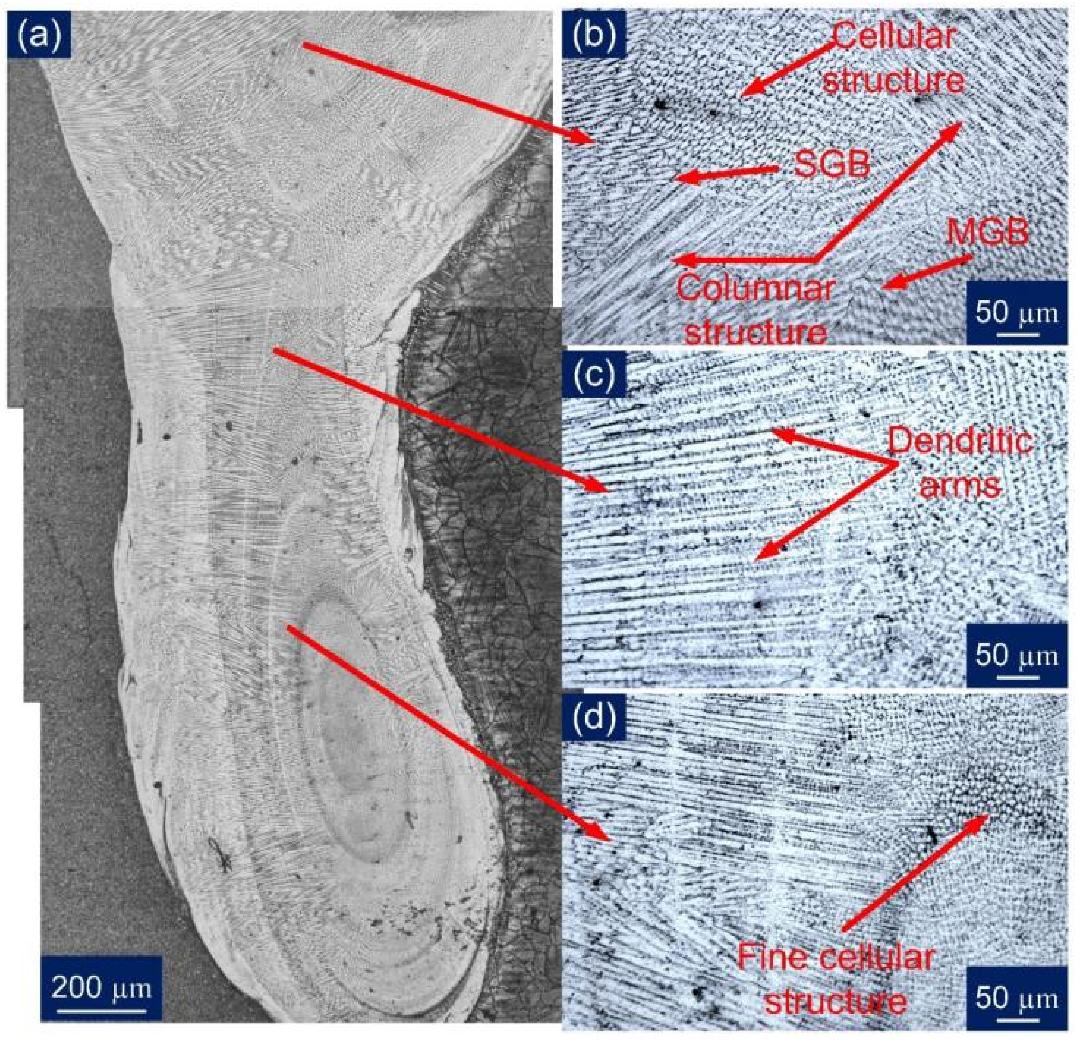
- Microstructural analysis of the weld fusion zone confirmed the presence of columnar, cellular, and equiaxed dendrites distributed in a random fashion. A substantial amount of detrimental elongated columnar dendritic structure was also witnessed. Formation of the unmixed zone near the P91 interface and partially mixed zone near the Incoloy 800HT interface were also observed. In addition, macrosegregation in the form of a peninsula and island was found at the weld fusion boundary of P91 and Incoloy 800HT.
- A comparatively thicker transition zone was formed at the Incoloy 800HT weld fusion boundary. The heat-affected zone of P91 was clearly distinguishable into the CGAHZ, FGHAZ, and ICHAZ zones, while Incoloy 800HT had no distinguishable HAZ formation; however, thickening of grain boundaries was witnessed near the weld fusion boundary of Incoloy 800HT, due to the Ti related precipitation activity near the grain boundary. PWHT did not have any effect on the observed macrosegregation, UZ, TZ, and PMZ.
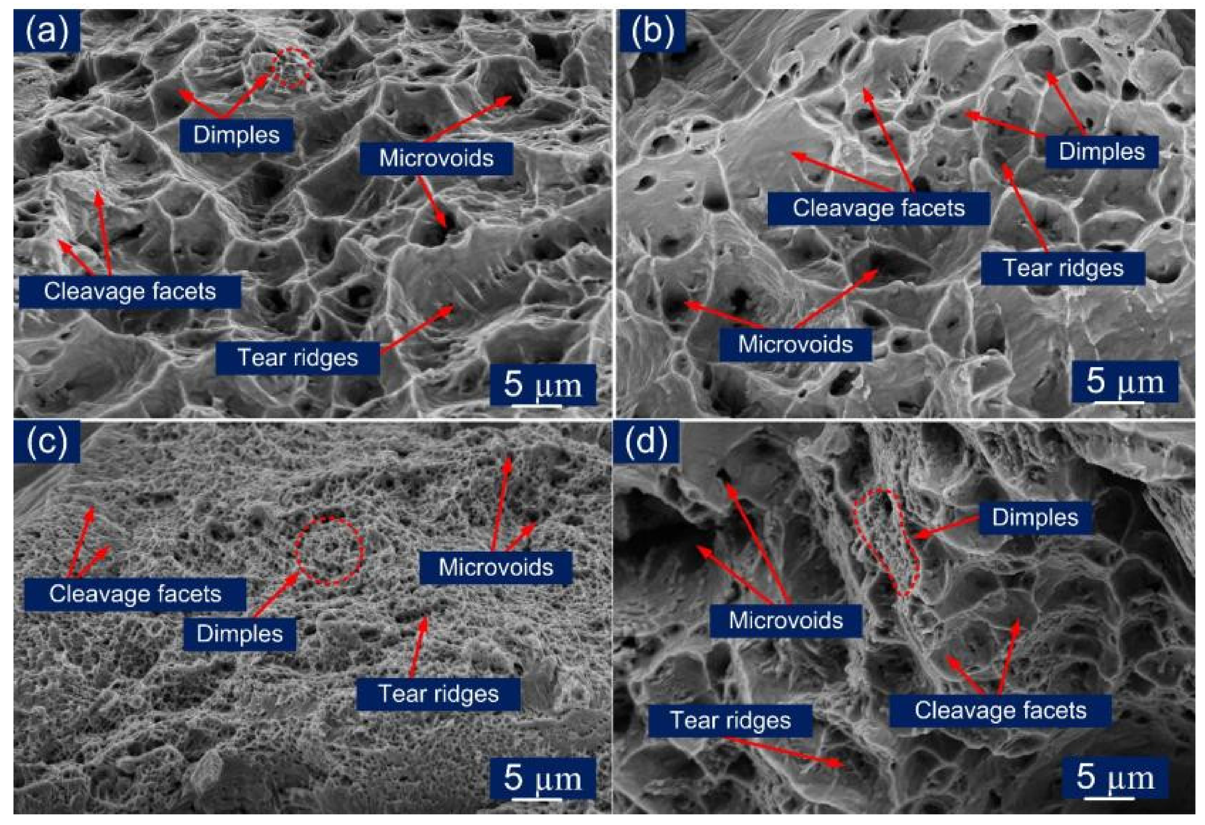
- The tensile strength and impact toughness obtained for the laser beam welded dissimilar joint of P91, and Incoloy 800HT met the boiler requirement. Furthermore, the Incoloy 800HT base metal and HAZ were the parts of the welded joint with relatively weak tensile strength, while the welded joint with relatively poor impact toughness was the weld fusion zone.
- The impact toughness of the weld fusion zone was obtained as 65 ± 4 J in the as-weld condition, which was lower than the parent metal P91 (105 ± 4 J) and Incoloy 800HT (102 ± 5 J). However, it was higher than the ASME standard value (>41 J) and EN 1599:1997 standard value (>47 J), which is required for the safe operation of power plants. The weld fusion zone showed poor impact toughness as compared with other zones of the weldments, and the inferior impact toughness of the weld fusion zone might be due to cracks in the WFZ and secondary carbide formation. The average impact toughness of the P91 HAZ (102 ± 5 J) and Incoloy 800HT HAZ (75 ± 3 J) was measured as lower than the respective base metal impact toughness. The weld fusion zone and Incoloy 800HT HAZ exhibited a noteworthy decrease in impact toughness after the PWHT; however, the impact toughness of P91 HAZ showed a minute increase.
- For a standard specimen, the tensile strength was obtained 546 ± 6 MPa and 576 ± 5 MPa for the as-welded and PWHT joints, respectively, which was lower than the base metals P91 and Incoloy 800HT. The standard tensile specimen of both the AW and PWHT condition failed from the Incoloy 800HT side, establishing it as the weakest part of the weld. For the subsize sample, tensile strength was measured 565 ± 5 MPa and 549 ± 4 MPa for as-weld and PWHT joints. The lowest tensile strength of 549 ± 4 MPa was observed for the PWHT subsize specimen owing to the presence of solidification cracks in the weld center as sudden fracture occurred. The cracks present in the weld center made it difficult to establish the effect of PWHT on the tensile strength.
- Microhardness characterization confirmed the presence of different zones formed as per the different ranges of temperature exposure while welding, which led to the hardness variation across the welded joint for both as-welded and PWHT joints. In the AW condition, a peak hardness of 391 HV was observed in P91 CGHAZ nearest to the fusion boundary owing to the complete dissolution of precipitates at high welding temperature. The minimum hardness of 218 HV was observed in ICHAZ due to the grain and precipitate coarsening. The Incoloy 800HT in AW condition had comparatively low hardness, and its HAZ had the hardness of 195 HV, which was comparable to the base metal owing to the presence of the austenitic structure. The weld fusion zone also had lower hardness in the uniform range of 187 ± 3 HV, again due to the austenitic structure of the weld fusion zone. The PWHT observed a minute effect on the hardness value of the weld fusion zone and Incoloy 800HT HAZ; however, a drastic reduction in P91 CGHAZ/FGHAZ was obtained.
- The outcome of this work can be worthy of exploring the laser-welded joining of the P91 and Incoloy 800HT as complete penetration was obtained in a single pass which is difficult to get using any conventional welding technique. In addition, the welding preparation is simple and avoids the use of any filler material. The focused laser beam single pass gives a narrower weld bead and narrower HAZ, limiting the mechanical properties’ variation.
Author Contributions
Funding
Institutional Review Board Statement
Informed Consent Statement
Data Availability Statement
Acknowledgments
Conflicts of Interest
References
- Liu, X.; Lu, F.; Yang, R.; Wang, P.; Xu, X.; Huo, X. Investigation on Mechanical Properties of 9%Cr/CrMoV Dissimilar Steels Welded Joint. J. Mater. Eng. Perform. 2015, 24, 1434–1440. [Google Scholar] [CrossRef]
- ASTM A335 Standard Specification for Seamless Ferritic Alloy-Steel Pipe for High-Temperature; ASTM International: West Conshohocken, PA, USA, 2003; pp. 1–11. [CrossRef]
- Pandey, C.; Mahapatra, M.; Kumar, P.; Saini, N. Homogenization of P91 weldments using varying normalizing and tempering treatment. Mater. Sci. Eng. A 2018, 710, 86–101. [Google Scholar] [CrossRef]
- Klueh, R.L. Ferritic/martensitic steels for advanced nuclear reactors. Trans. Indian Inst. Met. 2009, 62, 81–87. [Google Scholar] [CrossRef]
- Klueh, R.L. Elevated temperature ferritic and martensitic steels and their application to future nuclear reactors. Int. Mater. Rev. 2005, 50, 287–310. [Google Scholar] [CrossRef] [Green Version]
- Sirohi, S.; Pandey, C.; Goyal, A. Role of the Ni-based filler (IN625) and heat-treatment on the mechanical performance of the GTA welded dissimilar joint of P91 and SS304H steel. J. Manuf. Process. 2021, 65, 174–189. [Google Scholar] [CrossRef]
- Ren, W.; Swindeman, R. A Review of Alloy 800H for Applications in the Gen IV Nuclear Energy Systems. In Proceedings of the ASME 2010 Pressure Vessels and Piping Conference: Volume 6, Parts A and B, Washington, DC, USA, 18–20 July 2010; pp. 821–836. [Google Scholar] [CrossRef]
- Sharma, P.; Dwivedi, D.K. Comparative study of activated flux-GTAW and multipass-GTAW dissimilar P92 steel-304H ASS joints. Mater. Manuf. Process. 2019, 34, 1195–1204. [Google Scholar] [CrossRef]
- Gope, D.K.; Chattopadhyaya, S. Dissimilar Welding of Nickel Based Superalloy with Stainless Steel: Influence of Post Weld Heat Treatment. Mater. Manuf. Process. 2021, 1–7. [Google Scholar] [CrossRef]
- Chludzinski, M.; dos Santos, R.; Churiaque, C.; Ortega-Iguña, M.; Sánchez-Amaya, J. Pulsed Laser Welding Applied to Metallic Materials—A Material Approach. Metals 2021, 11, 640. [Google Scholar] [CrossRef]
- Akram, J.; Kalvala, P.R.; Chalavadi, P.; Misra, M. Dissimilar Metal Weld Joints of P91/Ni Alloy: Microstructural Characterization of HAZ of P91 and Stress Analysis at the Weld Interfaces. J. Mater. Eng. Perform. 2018, 27, 4115–4128. [Google Scholar] [CrossRef]
- Saini, N.; Pandey, C.; Mahapatra, M.M. Microstructure Evolution and Mechanical Properties of Dissimilar Welded Joint of P911 and P92 Steel for Subsequent PWHT and N&T Treatment. Trans. Indian Inst. Met. 2017, 1–14. [Google Scholar] [CrossRef]
- ASTM B409 Standard Specification for Nickel-Iron-Chromium Alloy Plate, Sheet, and Strip; ASTM International: West Conshohocken, PA, USA, 2011; Volume 6, pp. 1–5. [CrossRef]
- Maurya, A.K.; Pandey, C.; Chhibber, R. Dissimilar welding of duplex stainless steel with Ni alloys: A review. Int. J. Press. Vessel. Pip. 2021, 192, 104439. [Google Scholar] [CrossRef]
- Rakoczy, Ł.; Rutkowski, B.; Grudzień-Rakoczy, M.; Cygan, R.; Ratuszek, W.; Zielińska-Lipiec, A. Analysis of γ′ Precipitates, Carbides and Nano-Borides in Heat-Treated Ni-Based Superalloy Using SEM, STEM-EDX, and HRSTEM. Materials 2020, 13, 4452. [Google Scholar] [CrossRef]
- Kumar, S.A.; Sathiya, P. Experimental Investigation of the A-TIG Welding Process of Incoloy 800H. Mater. Manuf. Process. 2015, 30, 1154–1159. [Google Scholar] [CrossRef]
- Xu, L.; Zhu, P.; Jing, H.; Guo, K.; Zhong, S.; Han, Y. Failure analysis of Incoloy 800HT pipe at high temperature. Eng. Fail. Anal. 2013, 31, 375–386. [Google Scholar] [CrossRef]
- Shuai, J.; Zhao, J.; Lei, L.; Zeng, P.; Wu, X.; Sun, L. Characterization of crack propagation of Incoloy 800H by the combination of DIC and XFEM. Nucl. Eng. Des. 2020, 364, 110683. [Google Scholar] [CrossRef]
- Rogalski, G.; Świerczyńska, A.; Landowski, M.; Fydrych, D. Mechanical and Microstructural Characterization of TIG Welded Dissimilar Joints between 304L Austenitic Stainless Steel and Incoloy 800HT Nickel Alloy. Metals 2020, 10, 559. [Google Scholar] [CrossRef]
- Pańcikiewicz, K.; Świerczyńska, A.; Hućko, P.; Tumidajewicz, M. Laser Dissimilar Welding of AISI 430F and AISI 304 Stainless Steels. Materials 2020, 13, 4540. [Google Scholar] [CrossRef]
- Silva, C.C.; Miranda, H.C.; de Sant’Ana, H.B.; Farias, J.P. Austenitic and ferritic stainless steel dissimilar weld metal evaluation for the applications as-coating in the petroleum processing equipment. Mater. Des. 2013, 47, 1–8. [Google Scholar] [CrossRef]
- Dak, G.; Pandey, C. A critical review on dissimilar welds joint between martensitic and austenitic steel for power plant application. J. Manuf. Process. 2020, 58, 377–406. [Google Scholar] [CrossRef]
- Bhaduri, A.; Srinivasan, G.; Gill, T.; Mannan, S. Effect of aging on the microstructure and tensile properties of an alloy 800/9Cr-1Mo steel joint. Int. J. Press. Vessel. Pip. 1995, 61, 25–33. [Google Scholar] [CrossRef]
- Wojsyk, K.; Golański, G.; Jasak, J.; Słania, J.; Zieliński, A.; Urbańczyk, P. Influence of the Annealing Time After Welding on the Mechanical Properties of Welded Joint of T91 Steel. Arch. Met. Mater. 2016, 61, 1425–1430. [Google Scholar] [CrossRef]
- Akram, J.; Kalvala, P.R.; Misra, M.; Charit, I. Creep behavior of dissimilar metal weld joints between P91 and AISI 304. Mater. Sci. Eng. A 2017, 688, 396–406. [Google Scholar] [CrossRef] [Green Version]
- Awale, D.D.; Ballal, A.R.; Thawre, M.M. Dissimilar weld joints of P91 and 316LN for power plants Applications-A review. Mater. Today Proc. 2020, 28, 2505–2510. [Google Scholar] [CrossRef]
- Muthukumaran, V.; Bhaduri Kumar, A.; Baldev, R. Penetration Enhancing Flux Formulation for Tungsten Inert Gas (TIG) Welding of Austenitic Stainless Steel and its Application. US8097826B2, 17 January 2012. [Google Scholar]
- Dak, G.; Pandey, C. Experimental investigation on microstructure, mechanical properties, and residual stresses of dissimilar welded joint of martensitic P92 and AISI 304L austenitic stainless steel. Int. J. Press. Vessel. Pip. 2021, 194, 104536. [Google Scholar] [CrossRef]
- Kulkarni, A.; Dwivedi, D.; Vasudevan, M. Dissimilar metal welding of P91 steel-AISI 316L SS with Incoloy 800 and Inconel 600 interlayers by using activated TIG welding process and its effect on the microstructure and mechanical properties. J. Mater. Process. Technol. 2019, 274, 116280. [Google Scholar] [CrossRef]
- Pandey, C.; Mahapatra, M.M.; Kumar, P.; Saini, N. Dissimilar joining of CSEF steels using autogenous tungsten-inert gas welding and gas tungsten arc welding and their effect on δ-ferrite evolution and mechanical properties. J. Manuf. Process. 2018, 31, 247–259. [Google Scholar] [CrossRef]
- Pandey, C. Mechanical and Metallurgical Characterization of Dissimilar P92/SS304 L Welded Joints Under Varying Heat Treatment Regimes. Met. Mater. Trans. A 2020, 51, 2126–2142. [Google Scholar] [CrossRef]
- Wolf, D.M. Zur Phänomenologie der Heißrissbildung beim Schweißen und Entwicklung aussagekräftiger Prüfverfahren; Wirtschaftsverlag NW, Verlag für Neue Wissenschaften: Bremerhaven, Germany, 2006; ISBN 9783865095992. [Google Scholar]
- Laha, K.; Chandravathi, K.S.; Parameswaran, P.; Goyal, S.; Mathew, M.D. A Comparison of Creep Rupture Strength of Ferritic/Austenitic Dissimilar Weld Joints of Different Grades of Cr-Mo Ferritic Steels. Met. Mater. Trans. A 2012, 43, 1174–1186. [Google Scholar] [CrossRef]
- Silva, F.J.G.; Pinho, A.P.; Pereira, A.B.; Paiva, O.C. Evaluation of Welded Joints in P91 Steel under Different Heat-Treatment Conditions. Metals 2020, 10, 99. [Google Scholar] [CrossRef] [Green Version]
- Sridhar, S.P.; Kumar, S.A.; Sathiya, P. A study on the effect of different activating flux on A-TIG welding process of Incoloy 800H. Adv. Mater. Sci. 2016, 16, 26–37. [Google Scholar] [CrossRef] [Green Version]
- Pandey, C.; Mahapatra, M.M. Effect of Heat Treatment on Microstructure and Hot Impact Toughness of Various Zones of P91 Welded Pipes. J. Mater. Eng. Perform. 2016, 25, 2195–2210. [Google Scholar] [CrossRef]
- Sousa, V.; Silva, F.; Pinho, A.; Pereira, A.; Paiva, O. Enhancing Heat Treatment Conditions of Joints in Grade P91 Steel: Looking for More Sustainable Solutions. Metals 2021, 11, 495. [Google Scholar] [CrossRef]
- ASTM A370: Standard Test Methods and Definitions for Mechanical Testing of Steel Products; ASTM International: West Conshohocken, PA, USA, 2014; pp. 1–50. [CrossRef]
- Arivazhagan, B.; Prabhu, R.; Albert, S.K.; Kamaraj, M.; Sundaresan, S. Microstructure and Mechanical Properties of 9Cr-1Mo Steel Weld Fusion Zones as a Function of Weld Metal Composition. J. Mater. Eng. Perform. 2009, 18, 999–1004. [Google Scholar] [CrossRef]
- Khan, F.; Mahajan, S.; Khan, W.N.; Chhibber, R. Mechanical, microstructure, and hot corrosion investigations on P22/P91 dissimilar tungsten inert gas weld. Proc. Inst. Mech. Eng. Part L J. Mater. Des. Appl. 2021, 235, 2128–2141. [Google Scholar] [CrossRef]
- Mayr, P.; Cerjak, H. The impact of welding on the creep properties of advanced 9–12% Cr steels. Trans. Indian Inst. Met. 2010, 63, 131–136. [Google Scholar] [CrossRef]
- Pandey, C.; Mahapatra, M.M.; Kumar, P. Characterisation of dissimilar P91 and P92 steel welds joint. Mater. High Temp. 2019, 36, 275–284. [Google Scholar] [CrossRef]
- DuPont, J.N. Welding Metallurgy and Weldability of Nickel-Base Alloys; John Wiley & Sons: Hoboken, NJ, USA, 2011; ISBN 9780470087145. [Google Scholar]
- Nelson, T.W.; Lippold, J.C.; Mills, M.J. Investigation of boundaries and structures in dissimilar metal welds. Sci. Technol. Weld. Join. 1998, 3, 249–255. [Google Scholar] [CrossRef]
- Sireesha, M.; Shankar, V.; Albert, S.K.; Sundaresan, S. Microstructural features of dissimilar welds between 316LN austenitic stainless steel and alloy 800. Mater. Sci. Eng. A 2000, 292, 74–82. [Google Scholar] [CrossRef]
- Hosseini, H.S.; Shamanian, M.; Kermanpur, A. Characterization of microstructures and mechanical properties of Inconel 617/310 stainless steel dissimilar welds. Mater. Charact. 2011, 62, 425–431. [Google Scholar] [CrossRef]
- Radhakrishnan, B.; Thompson, R.G. A phase diagram approach to study liquation cracking in alloy 718. Met. Mater. Trans. A 1991, 22, 887–902. [Google Scholar] [CrossRef]
- Vellaichamy, L.; Gerard, P.B.T.; Paulraj, S. Mechanical and Metallurgical Characterization of Laser Welding on P91 Ferritic Steel and Incoloy 800HT Dissimilar Joints. Mater. Res. 2018, 21. [Google Scholar] [CrossRef] [Green Version]
- Wang, Y.; Kannan, R.; Li, L. Identification and Characterization of Intercritical Heat-Affected Zone in As-Welded Grade 91 Weldment. Met. Mater. Trans. A 2016, 47, 5680–5684. [Google Scholar] [CrossRef]
- Pandey, C.; Mahapatra, M.M.; Kumar, P.; Daniel, F.; Adhithan, B. Softening mechanism of P91 steel weldments using heat treatments. Arch. Civ. Mech. Eng. 2019, 19, 297–310. [Google Scholar] [CrossRef]
- El-Salam, M.A.E.-R.A.; El-Mahallawi, I.; El-Koussy, M.R. Influence of heat input and post-weld heat treatment on boiler steel P91 (9Cr–1Mo–V–Nb) weld joints Part 2—Mechanical properties. Int. Heat Treat. Surf. Eng. 2013, 7, 32–37. [Google Scholar] [CrossRef]
- Pandey, C.; Mahapatra, M.M.; Kumar, P.; Giri, A. Microstructure characterization and charpy toughness of P91 weldment for as-welded, post-weld heat treatment and normalizing & tempering heat treatment. Met. Mater. Int. 2017, 23, 900–914. [Google Scholar] [CrossRef]
- Maduraimuthu, V.; Vasudevan, M.; Muthupandi, V.; Bhaduri, A.K.; Jayakumar, T. Effect of Activated Flux on the Microstructure, Mechanical Properties, and Residual Stresses of Modified 9Cr-1Mo Steel Weld Joints. Met. Mater. Trans. A 2012, 43, 123–132. [Google Scholar] [CrossRef]
- Dehmolaei, R.; Shamanian, M.; Kermanpur, A. Microstructural changes and mechanical properties of Incoloy 800 after 15 years service. Mater. Charact. 2009, 60, 246–250. [Google Scholar] [CrossRef]
- Thakare, J.; Pandey, C.; Gupta, A.; Taraphdar, P.; Mahapatra, M. Role of the heterogeneity in microstructure on the mechanical performance of the Autogenous Gas Tungsten Arc (GTA) welded dissimilar joint of F/M P91 and SS304L steel. Fusion Eng. Des. 2021, 168, 112616. [Google Scholar] [CrossRef]
- Thakare, J.G.; Pandey, C.; Mahapatra, M.M.; Mulik, R.S. An assessment for mechanical and microstructure behavior of dissimilar material welded joint between nuclear grade martensitic P91 and austenitic SS304 L steel. J. Manuf. Process. 2019, 48, 249–259. [Google Scholar] [CrossRef]


| Materials | Fe | C | Si | Mn | Cr | Mo | Ni | Al | Nb | Ti | V | W |
|---|---|---|---|---|---|---|---|---|---|---|---|---|
| P91 | 88.8 | 0.0997 | 0.160 | 0.389 | 8.40 | 0.991 | 0.276 | 0.0111 | 0.0687 | 0.0023 | 0.207 | 0.0179 |
| Incoloy 800HT | 43.4 | 0.0838 | 0.464 | 1.02 | 21.1 | 0.124 | 32.7 | 0.353 | 0.0303 | 0.494 | 0.0501 | 0.0325 |
| Parameters | Values |
|---|---|
| Power | 4000 W |
| Speed | 7 mm/s |
| Heat input | 571 J/mm |
| Beam spot diameter | 0.6 mm |
| Focal length | 150 mm |
| Weld penetration | 6 mm |
| Weld angle | 90° |
| Specimens | Tensile Strength (MPa) | Yield Strength [offset 0.2%] (MPa) | Elongation (%) | Reduction of Area (%) | Impact Toughness (J) |
|---|---|---|---|---|---|
| P91 steel base metal | 687 ± 8 | 604 ± 6 | 39 ± 2 | 79 ± 3 | 105 ± 4 |
| Incoloy 800HT base metal | 593 ± 5 | 285 ± 4 | 10 ± 3 | 65 ± 3 | 102 ± 5 |
| Specimens | Tensile Strength (MPa) | Yield Strength [offset 0.2%] (MPa) | Elongation (%) | Reduction in Area (%) |
|---|---|---|---|---|
| AW (Standard specimen) | 546 ± 6 | 265 ± 4 | 25 ± 2 | 48 ± 4 |
| AW (Subsize specimen) | 565 ± 5 | 198 ± 3 | 22 ± 2 | 48 ± 5 |
| PWHT (Standard specimen) | 576 ± 5 | 297 ± 5 | 27 ± 3 | 53 ± 3 |
| PWHT (Subsize specimen) | 549 ± 4 | 206 ± 4 | 15 ± 2 | 40 ± 4 |
| Specimen | AW | PWHT |
|---|---|---|
| Standard | 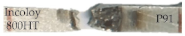 From Incoloy 800HT HAZ | 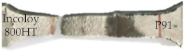 From Base Metal |
| Sub-size | 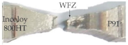 From WFZ | 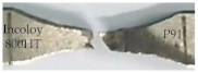 From WFZ |
| Specimens | Impact Zone | Charpy Impact Toughness (J) |
|---|---|---|
| AW | WFZ | 65 ± 4 |
| P91 HAZ | 102 ± 5 | |
| Incoloy 800HT HAZ | 75 ± 3 | |
| PWHT | WFZ | 55 ± 2 |
| P91 HAZ | 108 ± 6 | |
| Incoloy 800HT HAZ | 45 ± 3 |
Publisher’s Note: MDPI stays neutral with regard to jurisdictional claims in published maps and institutional affiliations. |
© 2021 by the authors. Licensee MDPI, Basel, Switzerland. This article is an open access article distributed under the terms and conditions of the Creative Commons Attribution (CC BY) license (https://creativecommons.org/licenses/by/4.0/).
Share and Cite
Bhanu, V.; Fydrych, D.; Gupta, A.; Pandey, C. Study on Microstructure and Mechanical Properties of Laser Welded Dissimilar Joint of P91 Steel and INCOLOY 800HT Nickel Alloy. Materials 2021, 14, 5876. https://doi.org/10.3390/ma14195876
Bhanu V, Fydrych D, Gupta A, Pandey C. Study on Microstructure and Mechanical Properties of Laser Welded Dissimilar Joint of P91 Steel and INCOLOY 800HT Nickel Alloy. Materials. 2021; 14(19):5876. https://doi.org/10.3390/ma14195876
Chicago/Turabian StyleBhanu, Vishwa, Dariusz Fydrych, Ankur Gupta, and Chandan Pandey. 2021. "Study on Microstructure and Mechanical Properties of Laser Welded Dissimilar Joint of P91 Steel and INCOLOY 800HT Nickel Alloy" Materials 14, no. 19: 5876. https://doi.org/10.3390/ma14195876
APA StyleBhanu, V., Fydrych, D., Gupta, A., & Pandey, C. (2021). Study on Microstructure and Mechanical Properties of Laser Welded Dissimilar Joint of P91 Steel and INCOLOY 800HT Nickel Alloy. Materials, 14(19), 5876. https://doi.org/10.3390/ma14195876