
Physicochemical and Biological Properties of Graphene-Oxide-Coated Metallic Materials

 , and
, and
Abstract
:
1. Introduction
2. Materials and Methods
2.1. Materials
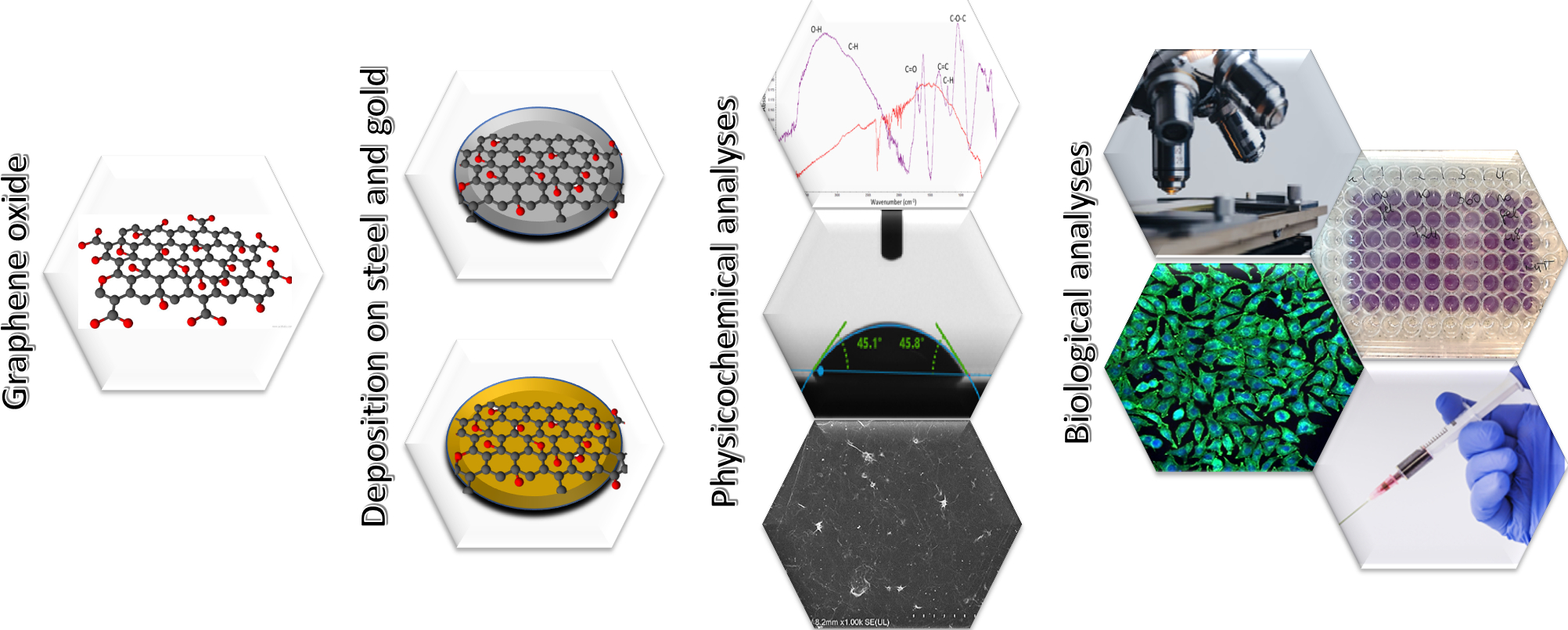
2.2. Synthesis and Characterization of Graphene Oxide
2.3. Preparation of Stainless Steel and Gold Substrates
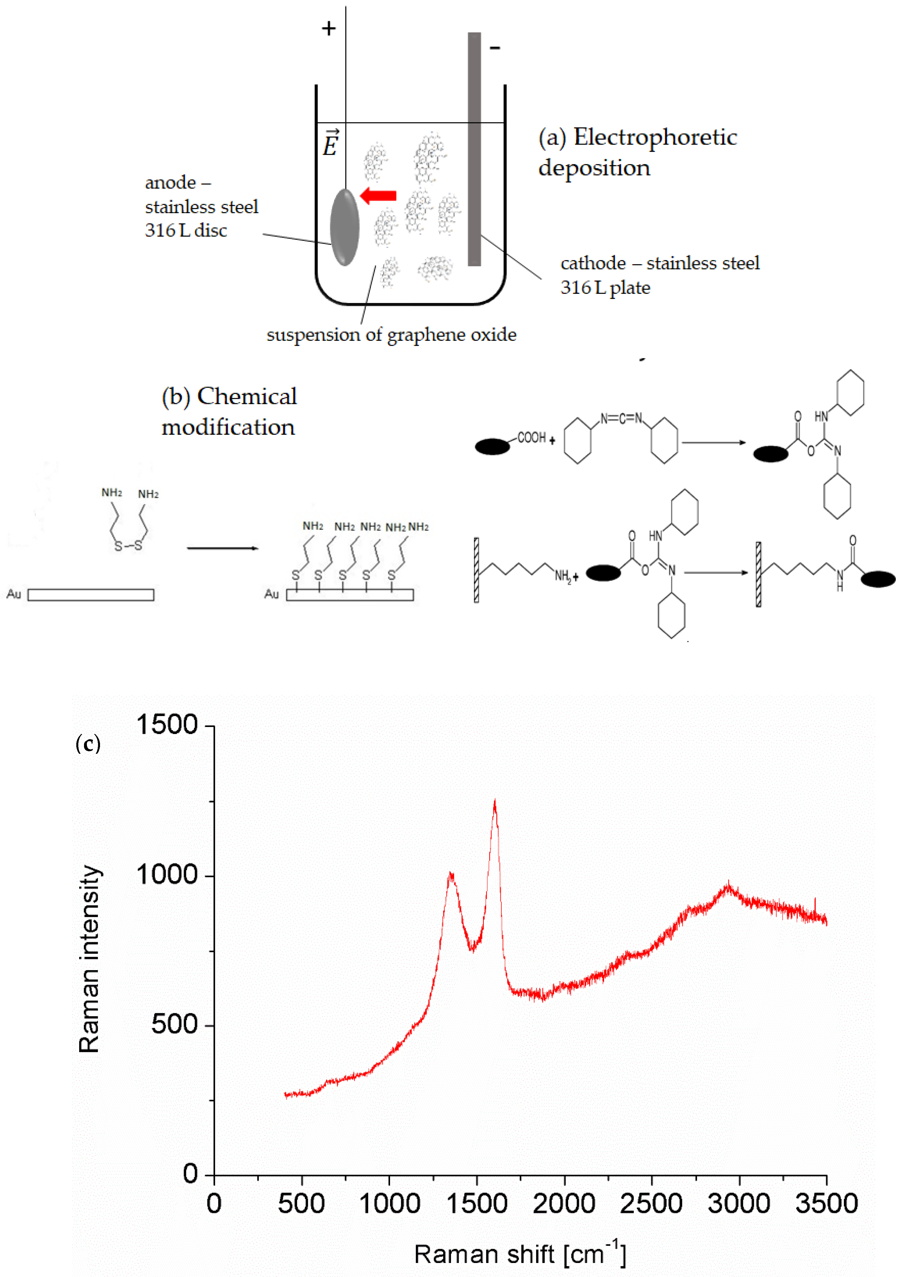
2.4. Electrophoretic Deposition of Graphene Oxide on a Stainless Steel Surface
2.5. Chemical Modification of the Gold Surface with Graphene Oxide
2.6. Physicochemical Properties of GO-Coated Metals
2.7. Biological Properties of GO-Coated Metals
2.7.1. Cell Viability Tests
2.7.2. Protein Adhesion on Surfaces of Obtained Materials
2.7.3. Hemolysis
2.7.4. Cell Adhesion on Surfaces of Obtained Materials
3. Results
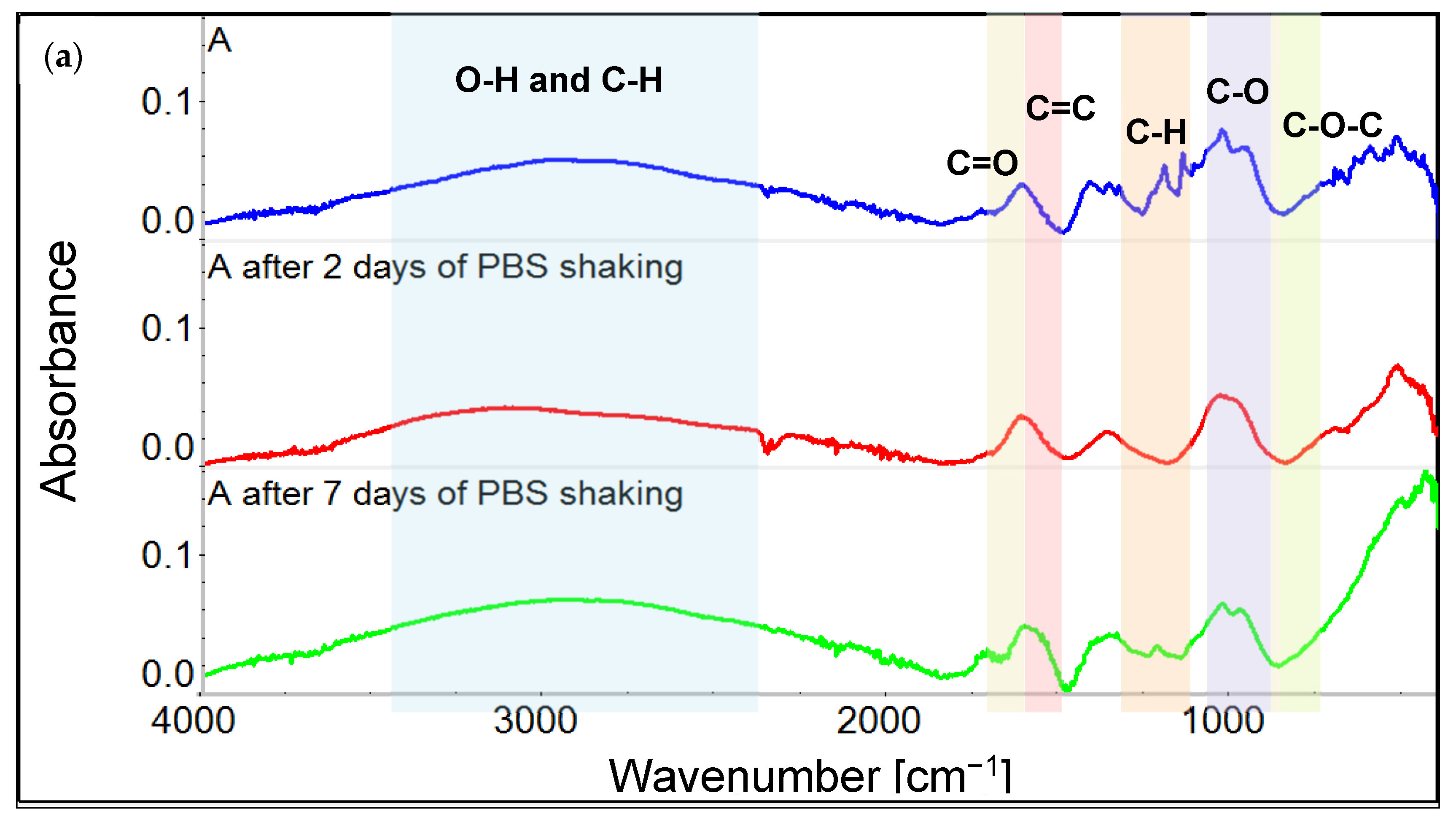
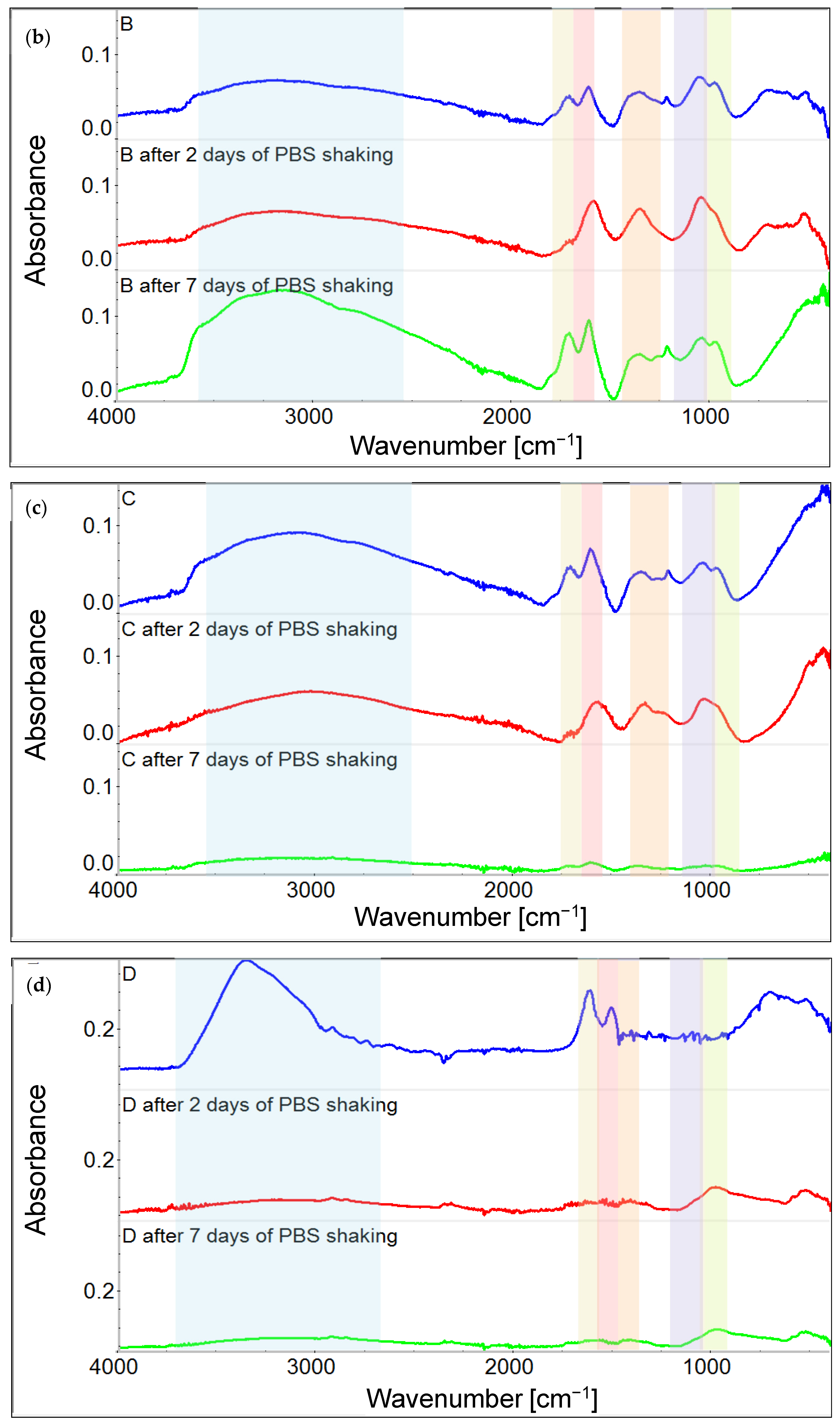
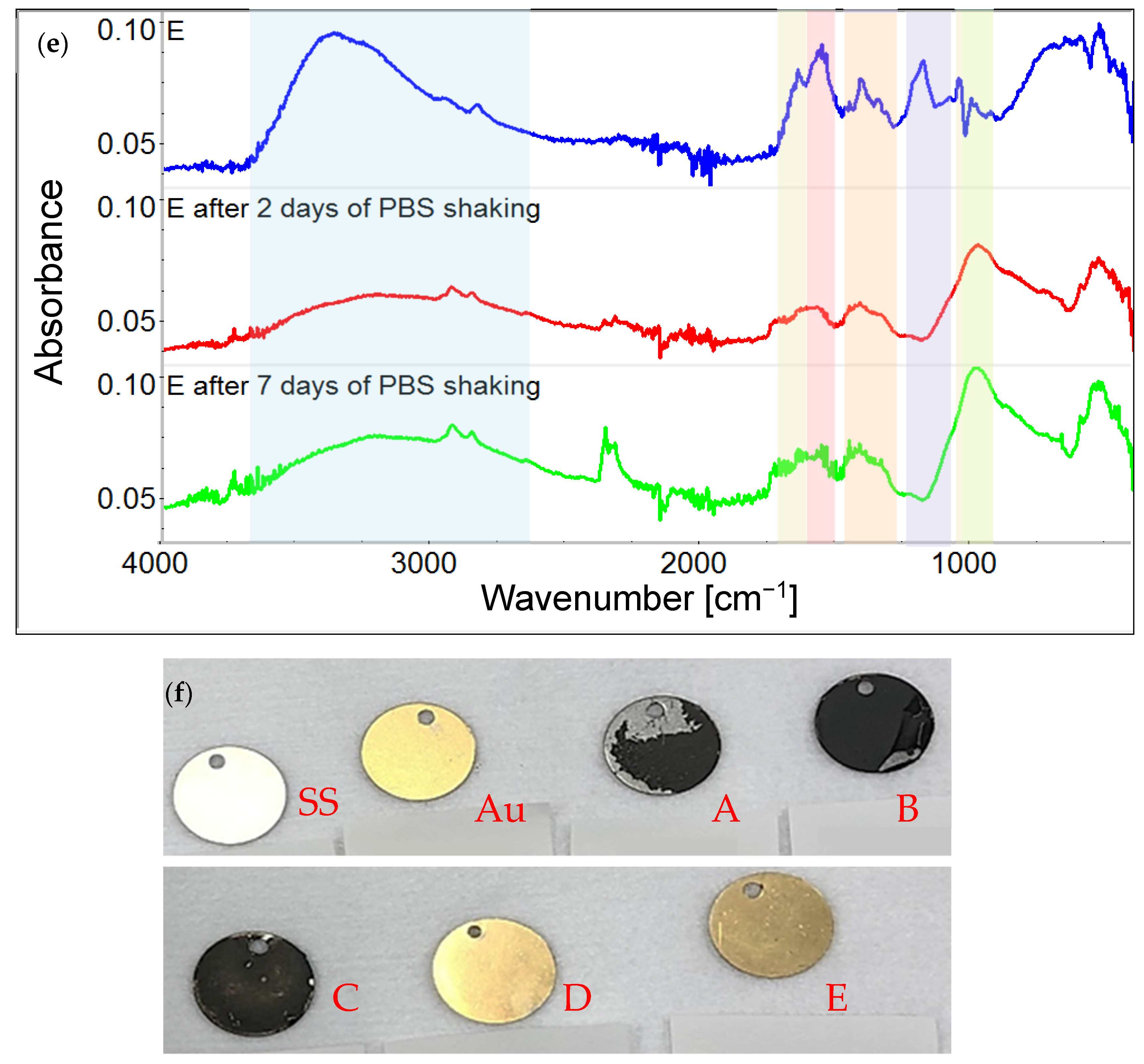
3.1. Chemical Characterization of Graphene Oxide and Obtained Coatings
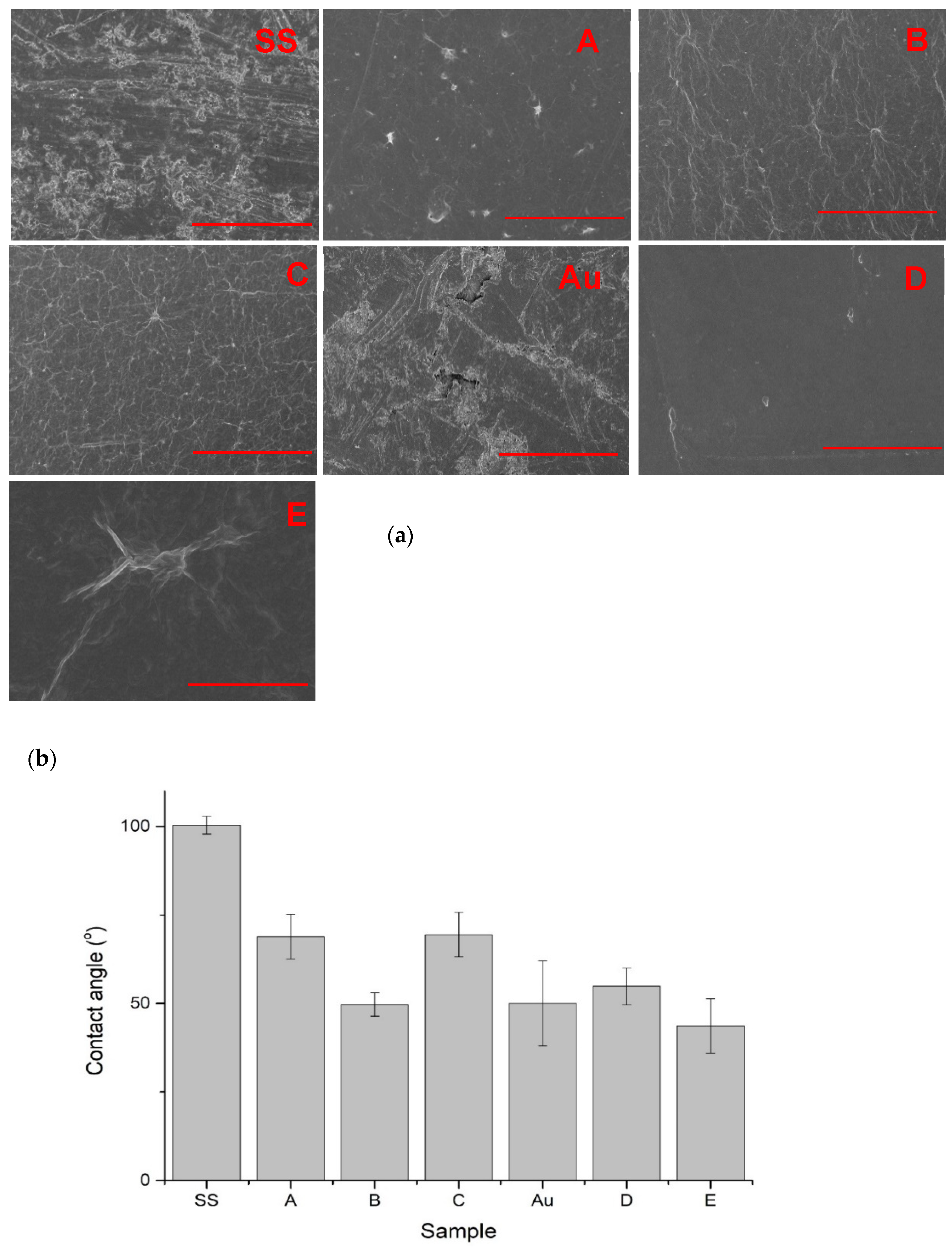
3.2. SEM Imaging
3.3. Contact Angle Measurements
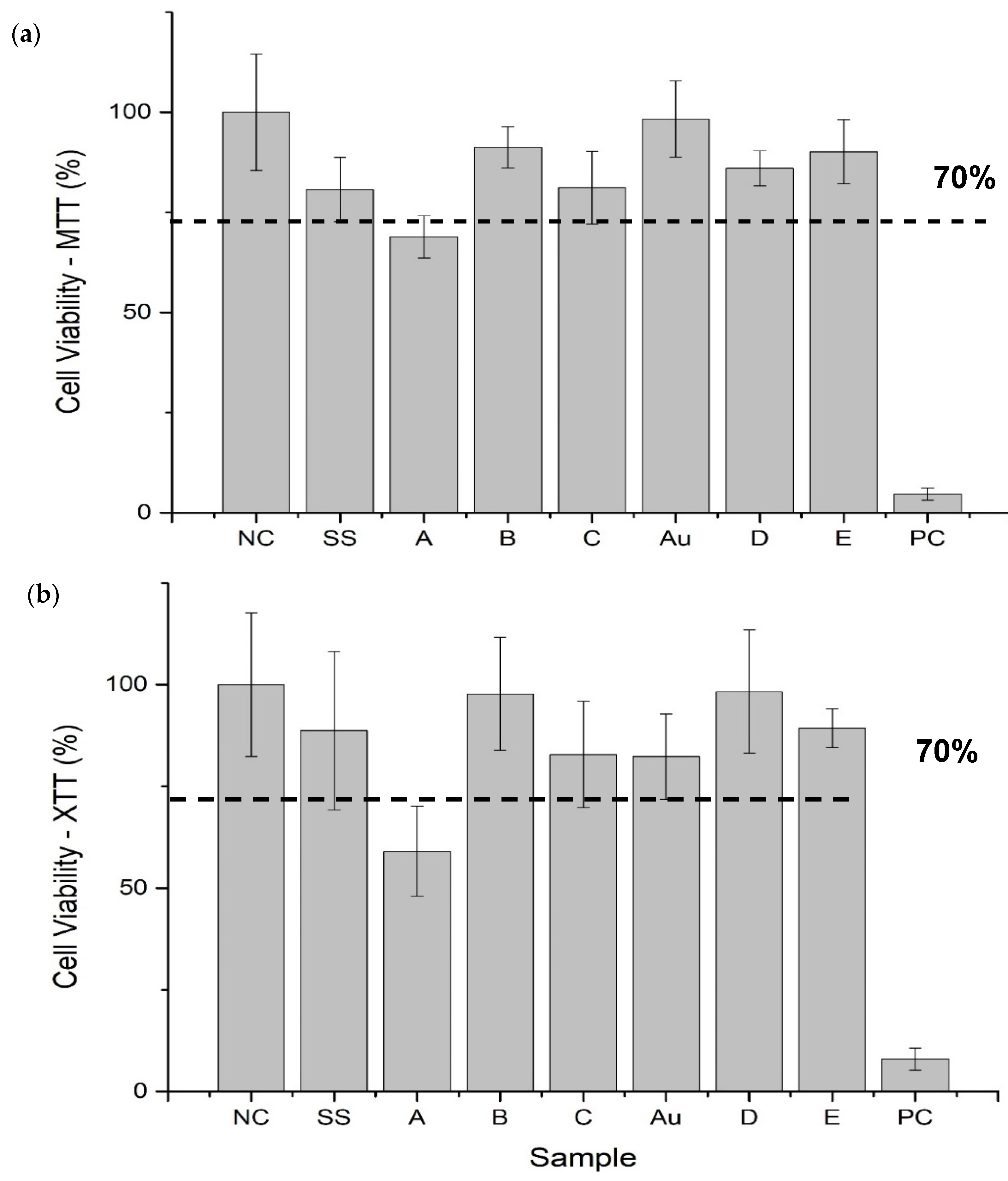
3.4. Cell Viability
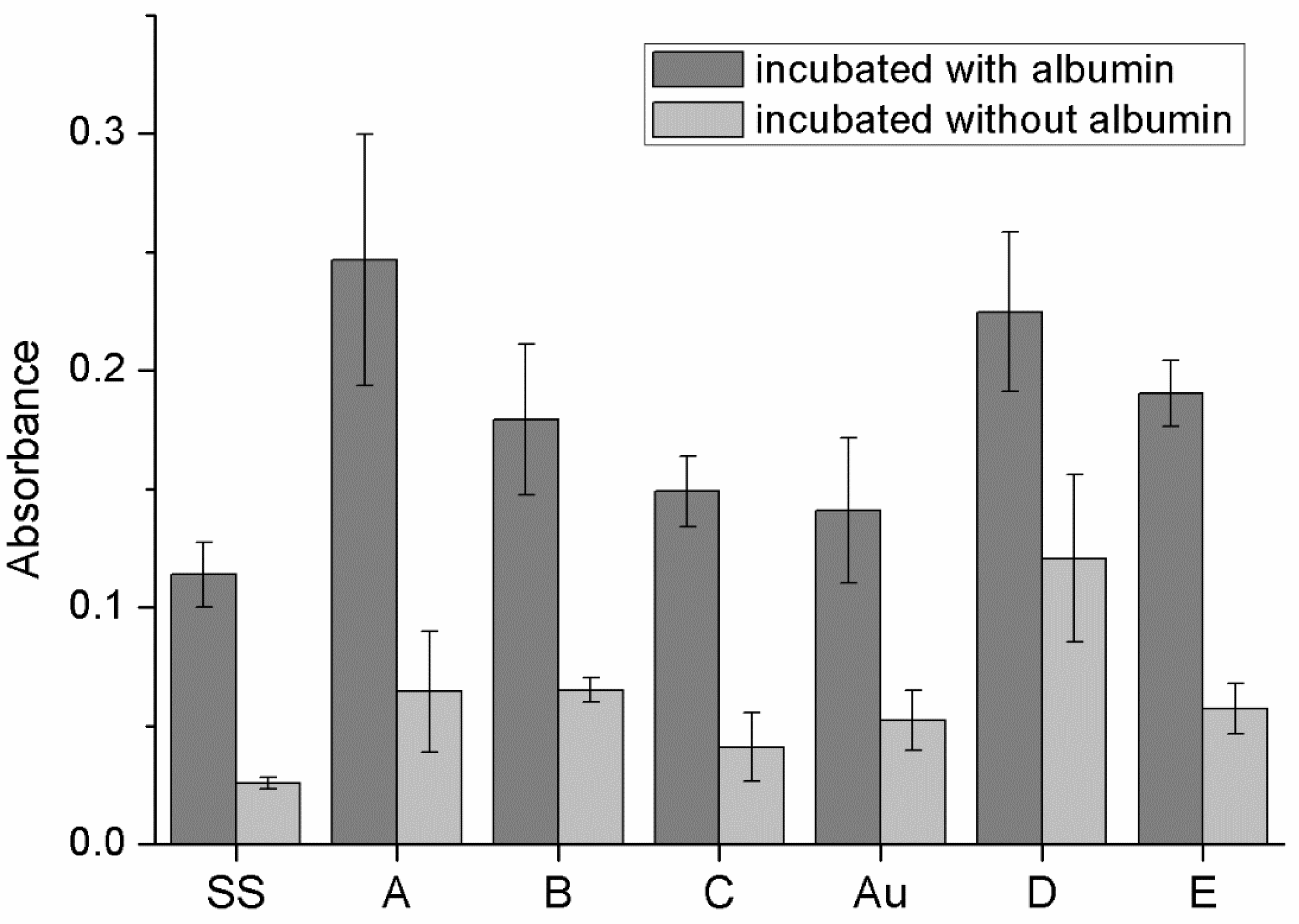
3.5. Protein Adhesion on Surfaces of Obtained Materials
3.6. Hemolysis
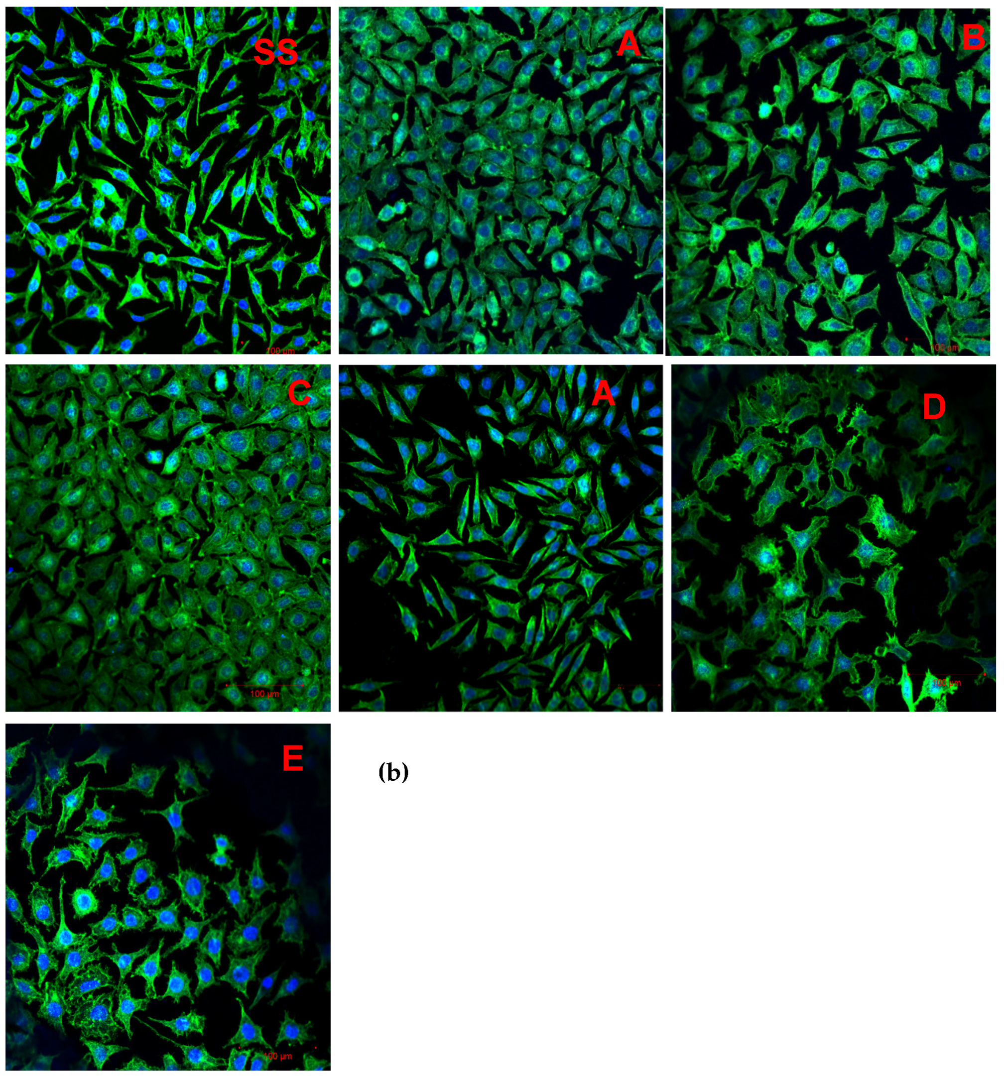
3.7. Cell Adhesion
4. Discussion
4.1. Chemistry of GO and Physicochemical Properties of GO-Coated Metals
4.2. Biological Properties of GO-Coated Metals
4.2.1. Cell Viability
4.2.2. Cell Adhesion
4.2.3. Protein Adhesion and Hemolysis
4.2.4. The Influence of the Solvent in GO Suspension Subjected to Electrodeposition on Steel
5. Conclusions
Author Contributions
Funding
Institutional Review Board Statement
Informed Consent Statement
Data Availability Statement
Conflicts of Interest
References
- Hermawan, H.; Ramdan, D.; Djuansjah, J.R. Metals for Biomedical Applications. Biomed. Eng. Theory Appl. 2011, 1, 411–431. [Google Scholar]
- Matsuno, H. Biocompatibility and osteogenesis of refractory metal implants, titanium, hafnium, niobium, tantalum and rhenium. Biomaterials 2001, 22, 1253–1262. [Google Scholar] [CrossRef]
- Qi, P.; Maitz, M.; Huang, N. Surface modification of cardiovascular materials and implants. Surf. Coat. Technol. 2013, 233, 80–90. [Google Scholar] [CrossRef]
- Farooqui, U.; Ahmad, A.; Hamid, N. Graphene oxide: A promising membrane material for fuel cells. Renew. Sustain. Energy Rev. 2018, 82, 714–733. [Google Scholar] [CrossRef]
- Amiri, A.; Baghayeri, M.; Karimabadi, F.; Ghaemi, F.; Maleki, B. Graphene oxide/polydimethylsiloxane-coated stainless steel mesh for use in solid-phase extraction cartridges and extraction of polycyclic aromatic hydrocarbons. Microchim. Acta 2020, 187, 1–8. [Google Scholar] [CrossRef] [PubMed]
- Manivasagam, G.; Dhinasekaran, D.; Rajamanickam, A. Biomedical Implants: Corrosion and its Prevention—A Review. Recent Patents Corros. Sci. 2010, 2, 40–54. [Google Scholar] [CrossRef] [Green Version]
- Ovcharenko, E.A.; Seifalian, A.; Rezvova, M.A.; Klyshnikov, K.; Glushkova, T.V.; Akenteva, T.N.; Antonova, L.V.; Velikanova, E.A.; Chernonosova, V.S.; Shevelev, G.Y.; et al. A New Nanocomposite Copolymer Based on Functionalised Graphene Oxide for Development of Heart Valves. Sci. Rep. 2020, 10, 5271. [Google Scholar] [CrossRef]
- Park, J.H.; Park, J.M. Electrophoretic deposition of graphene oxide on mild carbon steel for anti-corrosion application. Surf. Coat. Technol. 2014, 254, 167–174. [Google Scholar] [CrossRef]
- Rajitha, K.; Mohana, K.N.S.; Mohanan, A.; Madhusudhana, A.M. Evaluation of anti-corrosion performance of modified gelatin-graphene oxide nanocomposite dispersed in epoxy coating on mild steel in saline media. Colloids Surf. A Physicochem. Eng. Asp. 2020, 587, 124341. [Google Scholar] [CrossRef]
- Xu, Z.; Sun, M.; Liu, Z.; Wang, B.; Di, H. Properties of the iron bacteria biofouling on Ni-P-rGO coating. Appl. Sci. 2020, 10, 1567. [Google Scholar] [CrossRef] [Green Version]
- Cheng, W.; Lu, X.; Kaneda, M.; Zhang, W.; Bernstein, R.; Ma, J.; Elimelech, M. Graphene Oxide-Functionalized Membranes: The Importance of Nanosheet Surface Exposure for Biofouling Resistance. Environ. Sci. Technol. 2020, 54, 517–526. [Google Scholar] [CrossRef]
- Fathi, A.M.; Ahmed, M.K.; Afifi, M.; Menazea, A.A.; Uskoković, V. Taking Hydroxyapatite-Coated Titanium Implants Two Steps Forward: Surface Modification Using Graphene Mesolayers and a Hydroxyapatite-Reinforced Polymeric Scaffold. ACS Biomater. Sci. Eng. 2021, 7, 360–372. [Google Scholar] [CrossRef]
- Kim, B.-S.; La, W.-G.; Jin, M.; Park, S.; Yoon, H.-H.; Jeong, G.-J.; Bhang, S.H.; Park, H.; Char, K. Delivery of bone morphogenetic protein-2 and substance P using graphene oxide for bone regeneration. Int. J. Nanomed. 2014, 9, 107–116. [Google Scholar] [CrossRef] [Green Version]
- Ahmed, M.; Menazea, A.; Mansour, S.; Al-Wafi, R. Differentiation between cellulose acetate and polyvinyl alcohol nanofibrous scaffolds containing magnetite nanoparticles/graphene oxide via pulsed laser ablation technique for tissue engineering applications. J. Mater. Res. Technol. 2020, 9, 11629–11640. [Google Scholar] [CrossRef]
- Liang, C.; Luo, Y.; Yang, G.; Xia, D.; Liu, L.; Zhang, X.; Wang, H. Graphene Oxide Hybridized nHAC/PLGA Scaffolds Facilitate the Proliferation of MC3T3-E1 Cells. Nanoscale Res. Lett. 2018, 13, 1–10. [Google Scholar] [CrossRef] [Green Version]
- Yang, M.-C.; Tsou, H.-M.; Hsiao, Y.-S.; Cheng, Y.-W.; Liu, C.-C.; Huang, L.-Y.; Peng, X.-Y.; Liu, T.-Y.; Yung, M.-C.; Hsu, C.-C. Electrochemical polymerization of pedot–graphene oxide–heparin composite coating for anti-fouling. Polymers 2019, 11, 1520. [Google Scholar] [CrossRef] [PubMed] [Green Version]
- Ge, S.; Xi, Y.; Du, R.; Ren, Y.; Xu, Z.; Tan, Y.; Wang, Y.; Yin, T.; Wang, G. Inhibition of in-stent restenosis after graphene oxide double-layer drug coating with good biocompatibility. Regen. Biomater. 2019, 6, 299–309. [Google Scholar] [CrossRef] [PubMed]
- Liao, C.; Li, Y.; Tjong, S.C. Graphene Nanomaterials: Synthesis, Biocompatibility, and Cytotoxicity. Int. J. Mol. Sci. 2018, 19, 3564. [Google Scholar] [CrossRef] [PubMed] [Green Version]
- Loh, K.P.; Bao, Q.; Ang, P.K.; Yang, J. The chemistry of graphene. J. Mater. Chem. 2010, 20, 2277. [Google Scholar] [CrossRef]
- Marcano, D.C.; Kosynkin, D.V.; Berlin, J.M.; Sinitskii, A.; Sun, Z.; Slesarev, A.; Alemany, L.B.; Lu, W.; Tour, J.M. Improved Synthesis of Graphene Oxide. ACS Nano 2010, 4, 4806–4814. [Google Scholar] [CrossRef] [PubMed]
- Poniatowska, A.; Trzaskowski, M.; Ciach, T. Production and properties of top-down and bottom-up graphene oxide. Colloids Surfaces A: Physicochem. Eng. Asp. 2019, 561, 315–324. [Google Scholar] [CrossRef]
- International Organization for Standardization. Biological Evaluation of Medical Devices—Part 5: Tests for In Vitro Cytotoxicity; ISO 10993–5; Polish Committee for Standardization: Warsaw, Poland, 2019; Volume 5, pp. 1–52. [Google Scholar]
- Biological Evaluation of Medical Devices—Part 12: Sample Preparation and Reference Materials; ISO 10993-12:2012; Polish Committee for Standardization: Warsaw, Poland, 2012.
- Trzaskowska, P.; Poniatowska, A.; Tokarska, K.; Wiśniewski, C.; Ciach, T.; Malinowska, E. Promising electrodeposited biocompatible coatings for steel obtained from polymerized microemulsions. Colloids Surf. A Physicochem. Eng. Asp. 2020, 591, 124555. [Google Scholar] [CrossRef]
- ASTM F756-17, Standard Practice for Assessment of Hemolytic Properties of Materials; ASTM Int.: West Conshohocken, PA, USA, 2017.
- Huynh, N.M.N.; Boeva, Z.A.; Smått, J.-H.; Pesonen, M.; Lindfors, T. Reduced graphene oxide as a water, carbon dioxide and oxygen barrier in plasticized poly(vinyl chloride) films. RSC Adv. 2018, 8, 17645–17655. [Google Scholar] [CrossRef] [Green Version]
- Hidayah, N.M.S.; Liu, W.-W.; Lai, C.-W.; Noriman, N.Z.; Khe, C.-S.; Hashim, U.; Lee, H.C. Comparison on graphite, graphene oxide and reduced graphene oxide: Synthesis and characterization. AIP Conf. Proc. 2017, 150002. [Google Scholar] [CrossRef]
- Liu, Z.; Duan, X.; Zhou, X.; Qian, G.; Zhou, J.; Yuan, W. Controlling and Formation Mechanism of Oxygen-Containing Groups on Graphite Oxide. Ind. Eng. Chem. Res. 2014, 53, 253–258. [Google Scholar] [CrossRef]
- Hasan, S.A.; Rigueur, J.L.; Harl, R.R.; Krejci, A.J.; Gonzalo-Juan, I.; Rogers, B.; Dickerson, J.H. Transferable Graphene Oxide Films with Tunable Microstructures. ACS Nano 2010, 4, 7367–7372. [Google Scholar] [CrossRef] [PubMed]
- Pereira, A.T.; Henriques, P.C.; Schneider, K.H.; Pires, A.L.; Pereira, A.M.; Martins, M.C.; Magalhães, F.D.; Bergmeister, H.; Gonçalves, I.C. Graphene-based materials: The key for the successful application of pHEMA as a blood-contacting device. Biomater. Sci. 2021, 9, 3362–3377. [Google Scholar] [CrossRef] [PubMed]
- Oh, J.-S.; Jang, J.-H.; Lee, E.-J. Electrophoretic Deposition of a Hybrid Graphene Oxide/Biomolecule Coating Facilitating Controllable Drug Loading and Release. Metals 2021, 11, 899. [Google Scholar] [CrossRef]
- Fraczek-Szczypta, A.; Jantas, D.; Ciepiela, F.; Grzonka, J. Graphene oxide-conductive polymer nanocomposite coatings obtained by the EPD method as substrates for neurite outgrowth. Diam. Relat. Mater. 2020, 102, 107663. [Google Scholar] [CrossRef]
- Kang, M.S.; Jeong, S.J.; Lee, S.H.; Kim, B.; Hong, S.W.; Lee, J.H.; Han, D.-W. Reduced graphene oxide coating enhances osteogenic differentiation of human mesenchymal stem cells on Ti surfaces. Biomater. Res. 2021, 25, 1–9. [Google Scholar] [CrossRef]
- Jena, G.; Sofia, S.; Anandkumar, B.; Vanithakumari, S.; George, R.; Philip, J. Graphene oxide/polyvinylpyrrolidone composite coating on 316L SS with superior antibacterial and anti-biofouling properties. Prog. Org. Coatings 2021, 158, 106356. [Google Scholar] [CrossRef]
- Stango, S.A.X.; Vijayalakshmi, U. Electrolytic deposition of composite coatings on 316L SS and its in vitro corrosion resistive behavior in simulated body fluid solution. Chem. Pap. 2021, 1–13. [Google Scholar] [CrossRef]
- Jeong, J.-T.; Choi, M.-K.; Sim, Y.; Lim, J.-T.; Kim, G.-S.; Seong, M.-J.; Hyung, J.-H.; Kim, K.S.; Umar, A.; Lee, S.-K. Effect of graphene oxide ratio on the cell adhesion and growth behavior on a graphene oxide-coated silicon substrate. Sci. Rep. 2016, 6, 33835. [Google Scholar] [CrossRef]
- Khosravi, F.; Khorasani, S.N.; Khalili, S.; Neisiany, R.E.; Ghomi, E.R.; Ejeian, F.; Das, O.; Nasr-Esfahani, M.H. Development of a Highly Proliferated Bilayer Coating on 316L Stainless Steel Implants. Polymers 2020, 12, 1022. [Google Scholar] [CrossRef] [PubMed]
- Gurunathan, S.; Kim, J.-H. Synthesis, toxicity, biocompatibility, and biomedical applications of graphene and graphene-related materials. Int. J. Nanomed. 2016, 11, 1927–1945. [Google Scholar] [CrossRef] [Green Version]
- Linklater, D.P.; Baulin, V.A.; Juodkazis, S.; Ivanova, E.P. Mechano-bactericidal mechanism of graphene nanomaterials. Interface Focus 2018, 8, 20170060. [Google Scholar] [CrossRef] [Green Version]
- Trzaskowska, P.A.; Kuźmińska, A.; Butruk-Raszeja, B.; Rybak, E.; Ciach, T. Electropolymerized hydrophilic coating on stainless steel for biomedical applications. Colloids Surfaces B: Biointerfaces 2018, 167, 499–508. [Google Scholar] [CrossRef] [PubMed]
- Trzaskowska, P.A.; Poniatowska, A.; Trzaskowski, M.; Latocha, J.; Ozga, P.; Major, R.; Ciach, T. Lecithin suspensions for electrophoretic deposition on stainless steel coatings. Mater. Sci. Eng. C 2018, 93, 134–144. [Google Scholar] [CrossRef]
- Kim, D.-H.; Han, K.; Gupta, K.; Kwon, K.W.; Suh, K.-Y.; Levchenko, A. Mechanosensitivity of fibroblast cell shape and movement to anisotropic substratum topography gradients. Biomaterial 2009, 30, 5433–5444. [Google Scholar] [CrossRef] [PubMed] [Green Version]
- Simsikova, M.; Sikola, T. Interaction of Graphene Oxide with Proteins and Applications of their Conjugates. J. Nanomed. Res. 2017, 5, 1–4. [Google Scholar] [CrossRef]
- Liao, K.-H.; Lin, Y.-S.; Macosko, C.W.; Haynes, C. Cytotoxicity of Graphene Oxide and Graphene in Human Erythrocytes and Skin Fibroblasts. ACS Appl. Mater. Interfaces 2011, 3, 2607–2615. [Google Scholar] [CrossRef]
- Cai, B.; Hu, K.; Li, C.; Jin, J.; Hu, Y. Bovine serum albumin bioconjugated graphene oxide: Red blood cell adhesion and hemolysis studied by QCM-D. Appl. Surf. Sci. 2015, 356, 844–851. [Google Scholar] [CrossRef]
- Karimi, N.; Kharaziha, M.; Raeissi, K. Electrophoretic deposition of chitosan reinforced graphene oxide-hydroxyapatite on the anodized titanium to improve biological and electrochemical characteristics. Mater. Sci. Eng. C 2019, 98, 140–152. [Google Scholar] [CrossRef] [PubMed]
- Neklyudov, V.V.; Khafizov, N.R.; Sedov, I.; Dimiev, A.M. New insights into the solubility of graphene oxide in water and alcohols. Phys. Chem. Chem. Phys. 2017, 19, 17000–17008. [Google Scholar] [CrossRef] [PubMed] [Green Version]
- Liu, W.-W.; Xia, B.-Y.; Wang, X.-X.; Wang, J.-N. Exfoliation and dispersion of graphene in ethanol-water mixtures. Front. Mater. Sci. 2012, 6, 176–182. [Google Scholar] [CrossRef]


| Variant Description | |
|---|---|
| SS | Clean stainless steel disc |
| A | Stainless steel disc, electrochemically coated with GO from GO suspension 0.1% w/w in water |
| B | Stainless steel disc, electrochemically coated with GO from GO suspension 0.1% w/w in a mixture of water and ethanol in a ratio of 1:1 |
| C | Stainless steel disc electrochemically coated with GO from GO suspension 0.1% w/w in a mixture of water and ethanol in a ratio of 3:1 |
| Au | Gold-surface disc |
| D | Gold-surface disc dip-coated with GO 0.5% |
| E | Gold-surface disc with chemical coating: cystamine + GO |
| Variant Number | Absorbance | ±SD | %H |
|---|---|---|---|
| NC | 0.040 | 0.0004 | 0 |
| SS | 0.040 | 0.0006 | 0 |
| A | 0.040 | 0.0005 | 0 |
| B | 0.039 | 0.0009 | 0 |
| C | 0.040 | 0.0009 | 0 |
| Au | 0.040 | 0.0014 | 0 |
| D | 0.040 | 0.0007 | 0 |
| E | 0.041 | 0.0011 | 0.18 |
| PC | 0.417 | 0.0201 | 100 |
Publisher’s Note: MDPI stays neutral with regard to jurisdictional claims in published maps and institutional affiliations. |
© 2021 by the authors. Licensee MDPI, Basel, Switzerland. This article is an open access article distributed under the terms and conditions of the Creative Commons Attribution (CC BY) license (https://creativecommons.org/licenses/by/4.0/).
Share and Cite
Poniatowska, A.; Trzaskowska, P.A.; Trzaskowski, M.; Ciach, T. Physicochemical and Biological Properties of Graphene-Oxide-Coated Metallic Materials. Materials 2021, 14, 5752. https://doi.org/10.3390/ma14195752
Poniatowska A, Trzaskowska PA, Trzaskowski M, Ciach T. Physicochemical and Biological Properties of Graphene-Oxide-Coated Metallic Materials. Materials. 2021; 14(19):5752. https://doi.org/10.3390/ma14195752
Chicago/Turabian StylePoniatowska, Aleksandra, Paulina Anna Trzaskowska, Maciej Trzaskowski, and Tomasz Ciach. 2021. "Physicochemical and Biological Properties of Graphene-Oxide-Coated Metallic Materials" Materials 14, no. 19: 5752. https://doi.org/10.3390/ma14195752
APA StylePoniatowska, A., Trzaskowska, P. A., Trzaskowski, M., & Ciach, T. (2021). Physicochemical and Biological Properties of Graphene-Oxide-Coated Metallic Materials. Materials, 14(19), 5752. https://doi.org/10.3390/ma14195752