
Experimental Investigation on the Low Velocity Impact Response of Fibre Foam Metal Laminates


Abstract
:1. Introduction
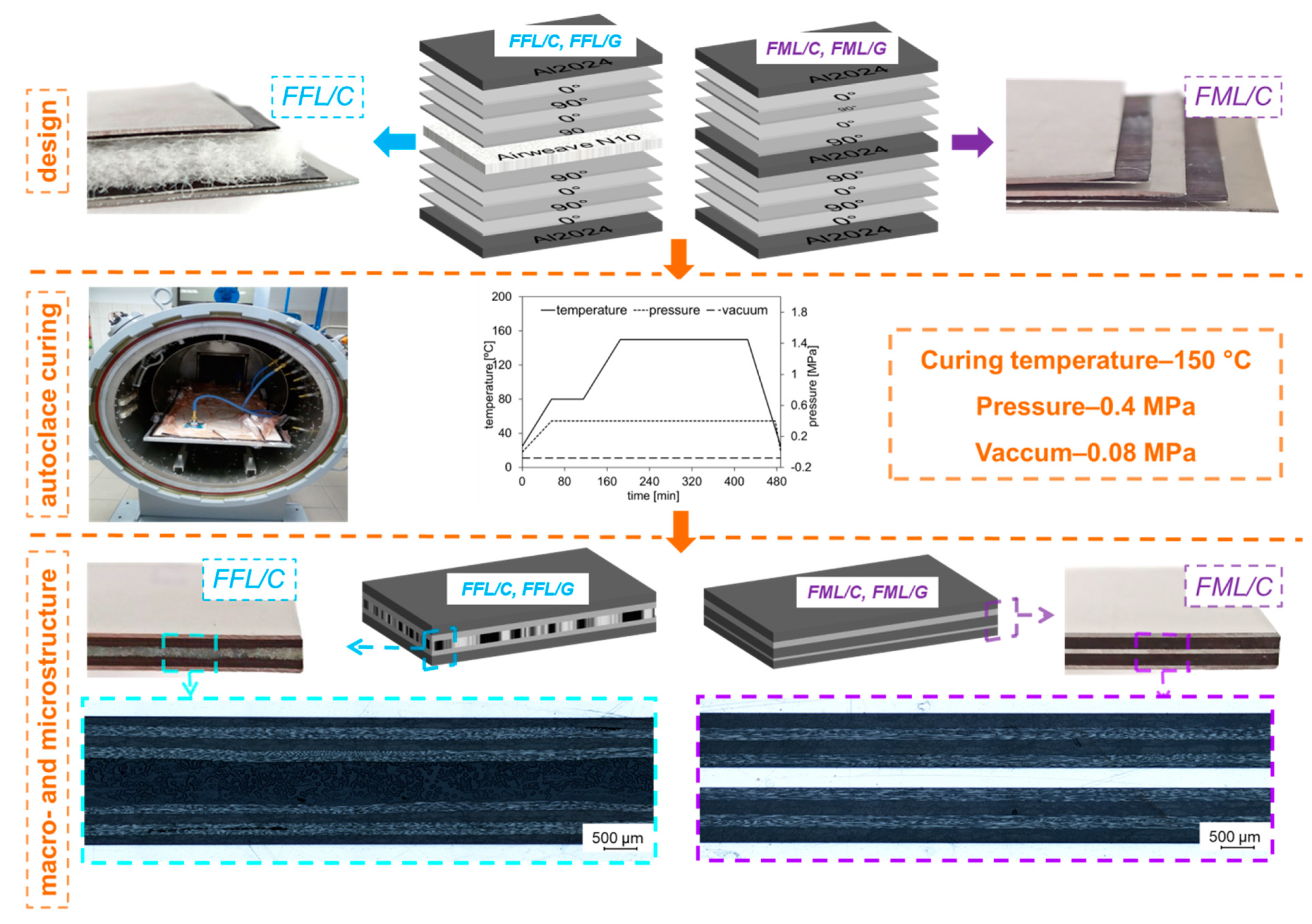
2. Materials and Methods
Impact Test and Damage Assessment
3. Results and Discussion
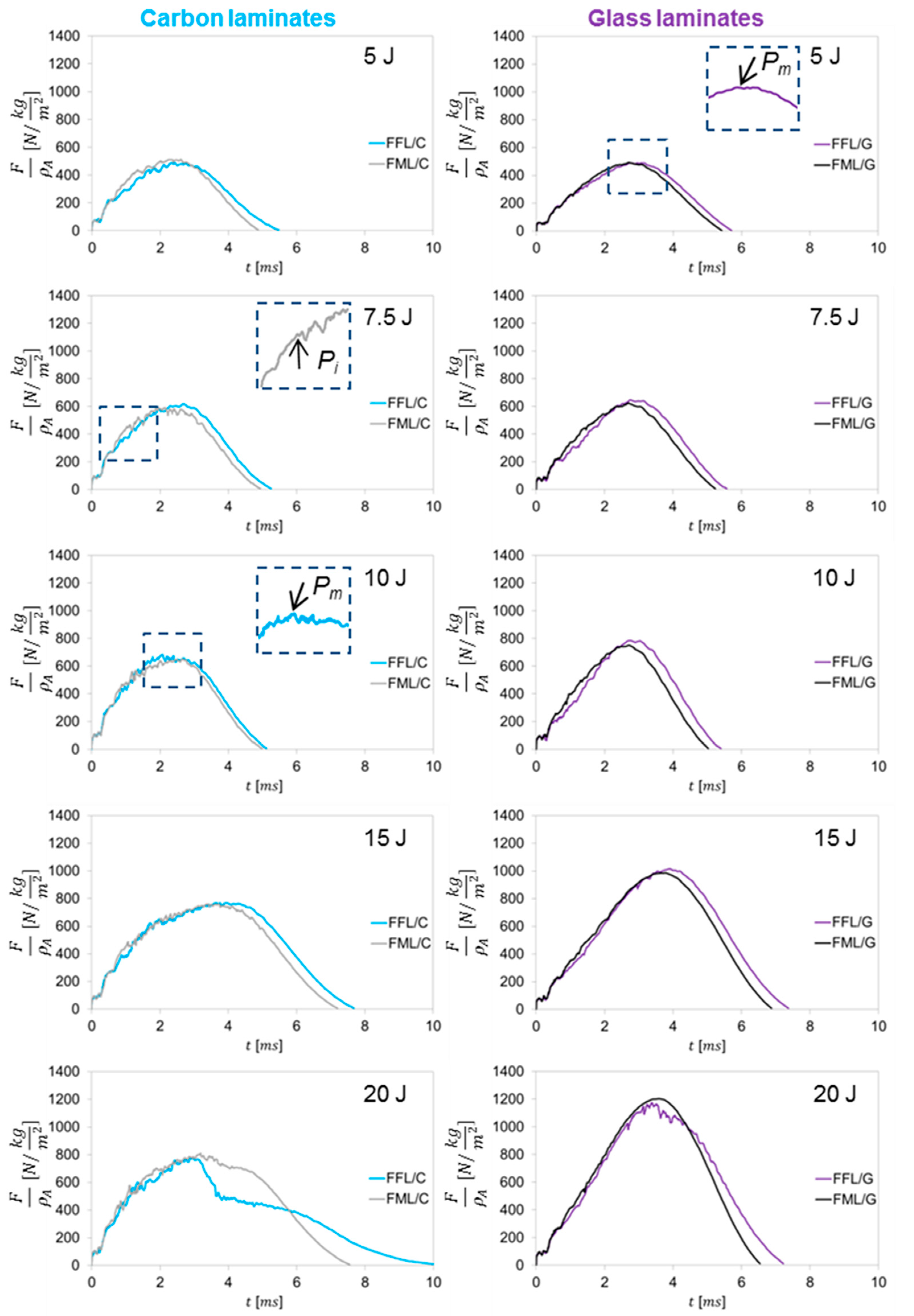
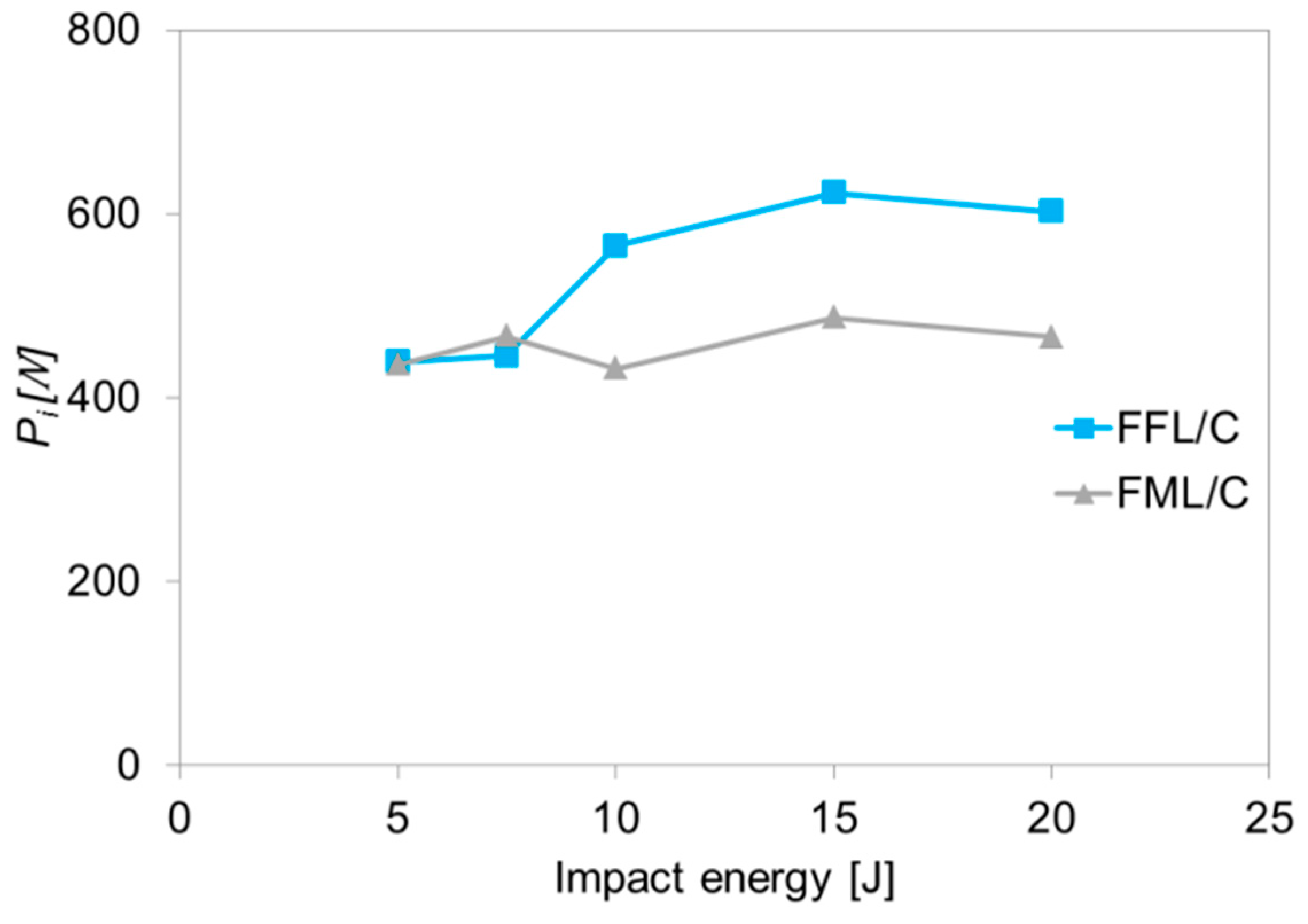
3.1. Force–Time Curves
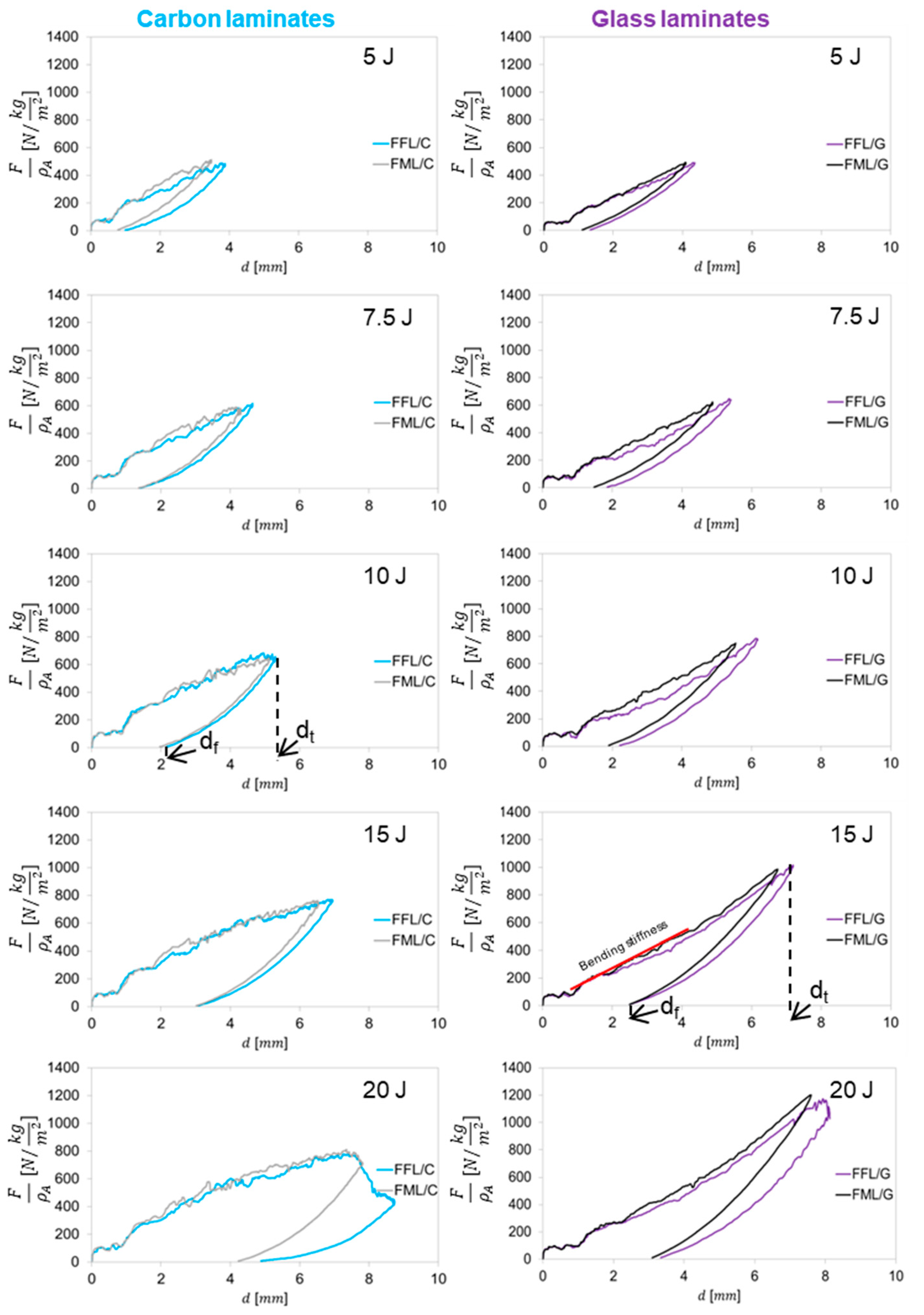
3.2. Force–Displacement
3.3. Energy Absorption
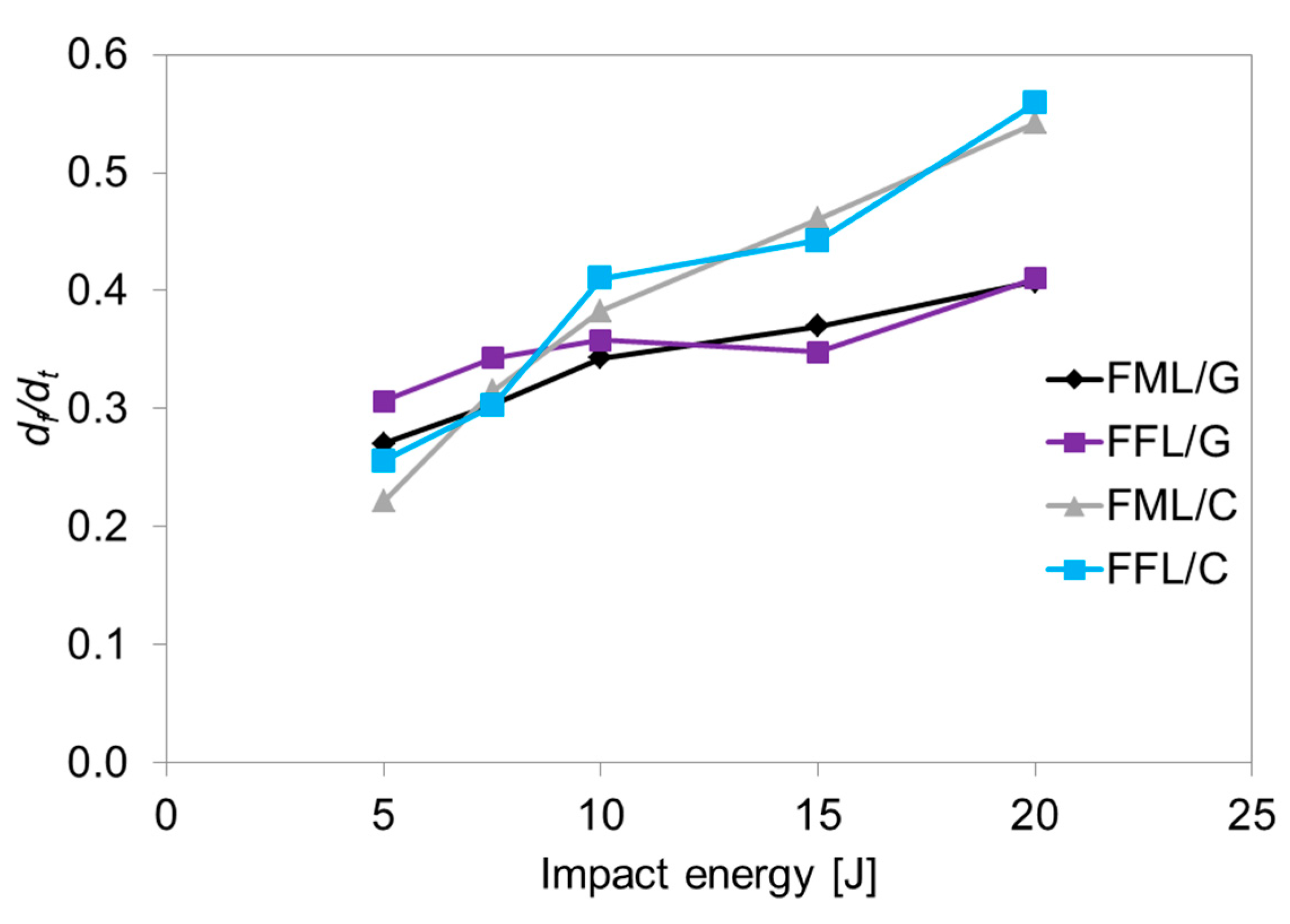
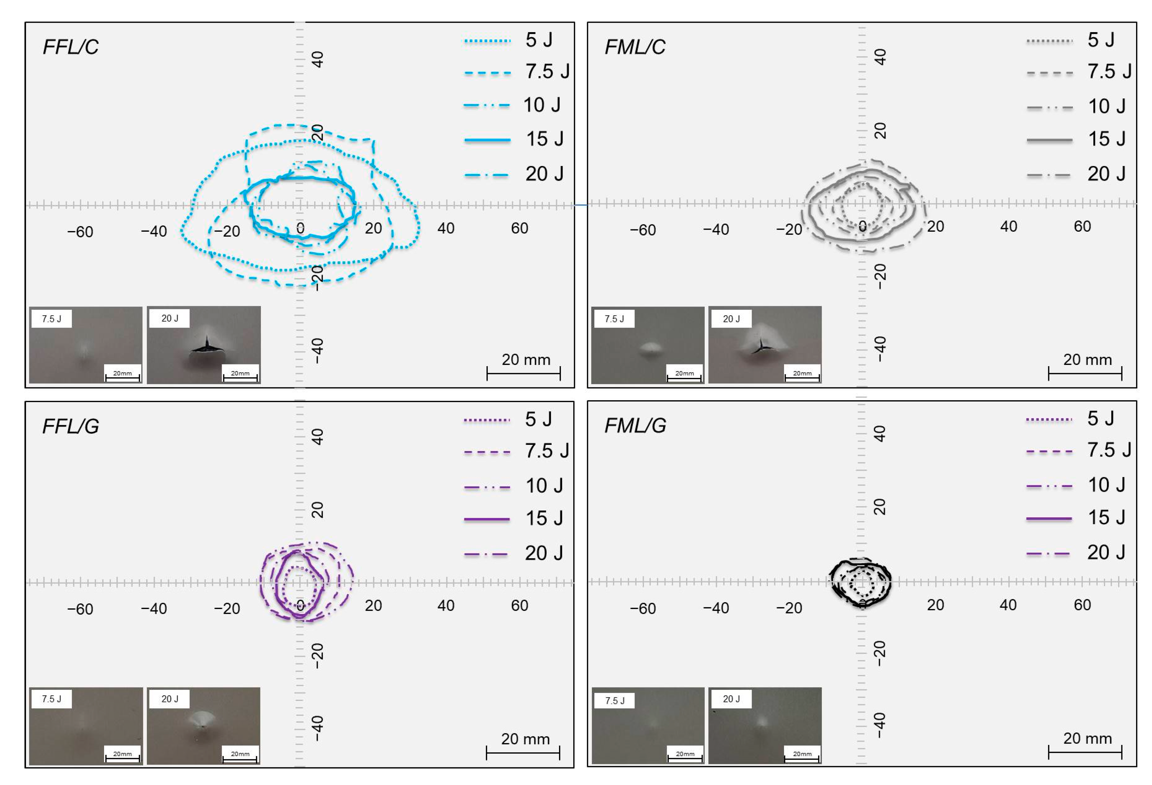
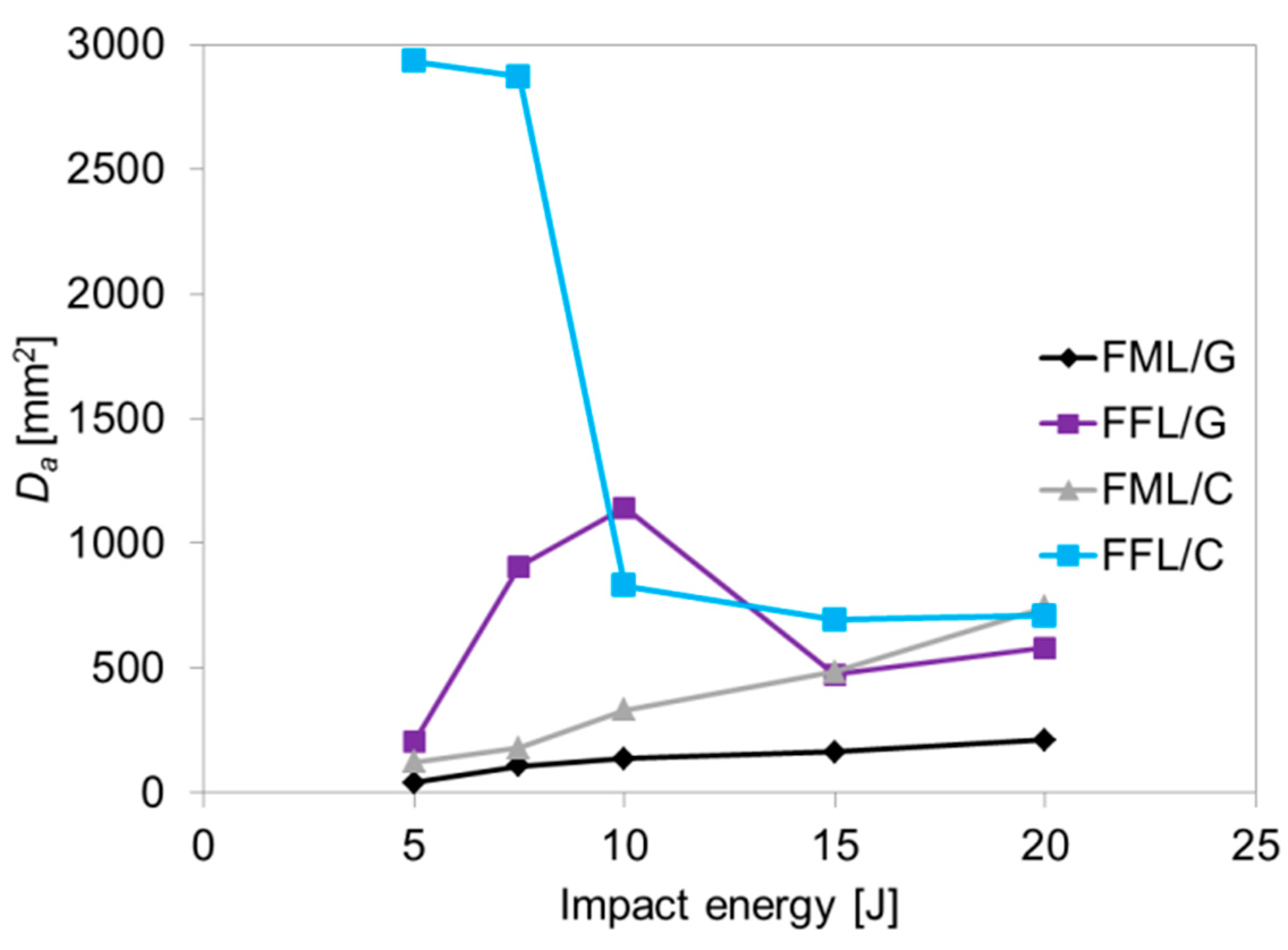
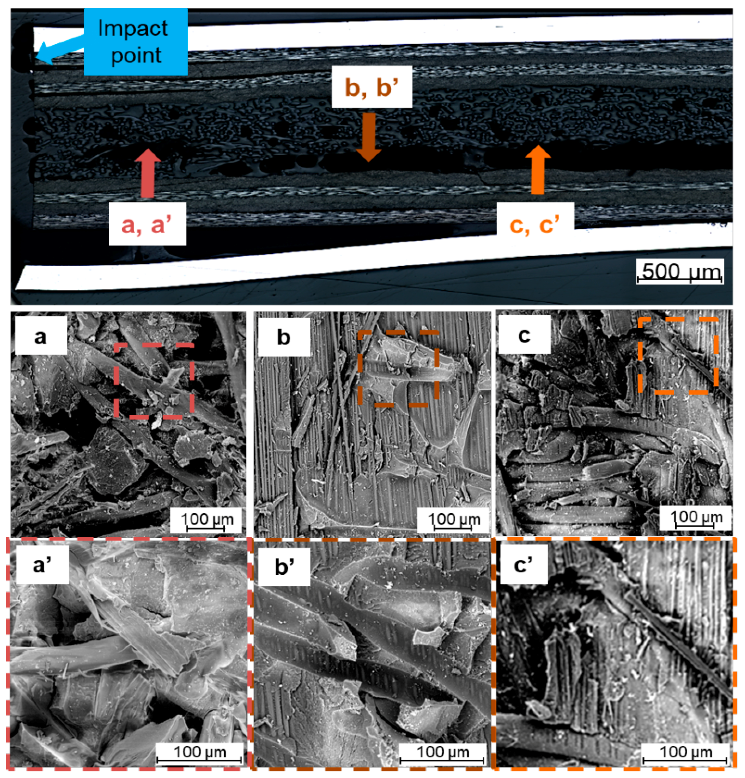
3.4. Damage Analysis
3.5. Failure Analysis
3.6. Fracture Analysis
4. Conclusions
- (1)
- The inclusion of the foam core leads to similar or higher impact resistance and significant changes in impact behavior in the studied energy range. The inclusion of a foam core does not reduce significantly the impact perforation resistance of the specimens.
- (2)
- The amount of absorbed energy by the foam fibre metal laminates was higher than the conventional ones. The after-impact damage analysis and fractography concludes that the energy absorbed by the foam and its influence in the damage apparition in the impact improve the specimen behaviour under impact.
- (3)
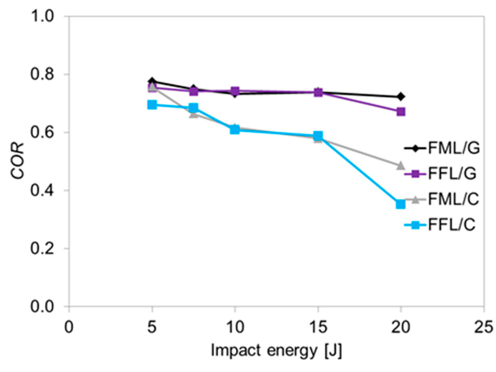
- The permanent deflection of the specimens after impact with foam cores is similar to that of conventional specimens. The buckling thread under compression after impact does not increase.
- (4)
- The better adhesion between the foam core and the composite than between the metal and composite plies results in a higher performance in terms of energy absorption of the specimens.
Author Contributions
Funding
Institutional Review Board Statement
Informed Consent Statement
Data Availability Statement
Acknowledgments
Conflicts of Interest
References
- Vlot, A.D.; Gunnink, J.W. Fibre Metal Laminates; Springer: Dordrecht, The Netherlands, 2001. [Google Scholar]
- Alderliesten, R.; Homan, J. Fatigue and damage tolerance issues of Glare in aircraft structures. Int. J. Fatigue 2006, 28, 1116–1123. [Google Scholar] [CrossRef]
- Jakubczak, P.; Bieniaś, J.; Droździel, M. The collation of impact behaviour of titanium/carbon, aluminum/carbon and conventional carbon fibres laminates. Thin-Walled Struct. 2020, 155, 106952. [Google Scholar] [CrossRef]
- Sadighi, M.; Alderliesten, R.; Benedictus, R. Impact resistance of fiber-metal laminates: A review. Int. J. Impact Eng. 2012, 49, 77–90. [Google Scholar] [CrossRef]
- Vogelesang, L.; Vlot, A. Development of fibre metal laminates for advanced aerospace structures. J. Mater. Process. Technol. 2000, 103, 1–5. [Google Scholar] [CrossRef]
- Richardson, M.; Wisheart, M. Review of low-velocity impact properties of composite materials. Compos. Part A Appl. Sci. Manuf. 1996, 27, 1123–1131. [Google Scholar] [CrossRef]
- Botelho, E.C.; Silva, R.A.; Pardini, L.C.; Rezende, M. A review on the development and properties of continuous fiber/epoxy/aluminum hybrid composites for aircraft structures. Mater. Res. 2006, 9, 247–256. [Google Scholar] [CrossRef]
- Sohn, M.; Hu, X.; Kim, J.-K.; Walker, L. Impact damage characterisation of carbon fibre/epoxy composites with multi-layer reinforcement. Compos. Part B Eng. 2000, 31, 681–691. [Google Scholar] [CrossRef]
- Bienias, J.; Jakubczak, P. Impact damage growth in carbon fibre aluminium laminates. Compos. Struct. 2017, 172, 147–154. [Google Scholar] [CrossRef]
- Pernas-Sánchez, J.; Artero-Guerrero, J.; Varas, D.; López-Puente, J. Experimental analysis of ice sphere impacts on unidirectional carbon/epoxy laminates. Int. J. Impact Eng. 2016, 96, 1–10. [Google Scholar] [CrossRef] [Green Version]
- Jakubczak, P.; Bieniaś, J.; Dadej, K. Experimantal and numerical investigation into the impact resistance of aluminium carbon laminates. Compos. Struct. 2020, 244, 112319. [Google Scholar] [CrossRef]
- Bienias, J.; Jakubczak, P.; Surowska, B.; Dragan, K. Low-energy impact behaviour and damage characterization of carbon fibre reinforced polymer and aluminium hybrid laminates. Arch. Civ. Mech. Eng. 2015, 15, 925–932. [Google Scholar] [CrossRef]
- Guan, Z.; Yang, C.Y. Low-Velocity Impact and Damage Process of Composite Laminates. J. Compos. Mater. 2002, 36, 851–871. [Google Scholar] [CrossRef]
- Choi, H.Y.; Chang, F.-K. A Model for Predicting Damage in Graphite/Epoxy Laminated Composites Resulting from Low-Velocity Point Impact. J. Compos. Mater. 1992, 26, 2134–2169. [Google Scholar] [CrossRef]
- Remmers, J.; de Borst, R. Delamination buckling of fibre–metal laminates. Compos. Sci. Technol. 2001, 61, 2207–2213. [Google Scholar] [CrossRef] [Green Version]
- Torre, L.; Kenny, J.M. Impact testing and simulation of composite sandwich structures for civil transportation. Compos. Struct. 2000, 50, 257–267. [Google Scholar] [CrossRef]
- Birman, V.; Kardomateas, G.A. Review of current trends in research and applications of sandwich structures. Compos. Part B Eng. 2018, 142, 221–240. [Google Scholar] [CrossRef]
- Tu, Z.; Shim, V.; Lim, C.T. Plastic deformation modes in rigid polyurethane foam under static loading. Int. J. Solids Struct. 2001, 38, 9267–9279. [Google Scholar] [CrossRef]
- Ren, P.; Tao, Q.; Yin, L.; Ma, Y.; Wu, J.; Zhao, W.; Mu, Z.; Guo, Z.; Zhao, Z. High-velocity impact response of metallic sandwich structures with PVC foam core. Int. J. Impact Eng. 2020, 144, 103657. [Google Scholar] [CrossRef]
- Alshamary, A.; Karakuzu, R.; Özdemir, O. Low-velocity impact response of sandwich composites with different foam core configurations. J. Sandw. Struct. Mater. 2016, 18, 754–768. [Google Scholar] [CrossRef]
- Caglayan, C.; Osken, I.; Ataalp, A.; Turkmen, H.S.; Cebeci, H. Impact response of shear thickening fluid filled polyurethane foam core sandwich composites. Compos. Struct. 2020, 243, 112171. [Google Scholar] [CrossRef]
- Wang, J.; Waas, A.M.; Wang, H. Experimental and numerical study on the low-velocity impact behavior of foam-core sandwich panels. Compos. Struct. 2013, 96, 298–311. [Google Scholar] [CrossRef]
- Zhou, J.; Hassan, M.Z.; Guan, Z.; Cantwell, W. The low velocity impact response of foam-based sandwich panels. Compos. Sci. Technol. 2012, 72, 1781–1790. [Google Scholar] [CrossRef]
- García-Castillo, S.K.; Buitrago, B.L.; Barbero, E. Behavior of sandwich structures and spaced plates subjected to high-velocity impacts. Polym. Compos. 2010, 32, 290–296. [Google Scholar] [CrossRef] [Green Version]
- Schubel, P.M.; Luo, J.-J.; Daniel, I.M. Low velocity impact behavior of composite sandwich panels. Compos. Part A Appl. Sci. Manuf. 2005, 36, 1389–1396. [Google Scholar] [CrossRef]
- Anderson, T.; Madenci, E. Experimental investigation of low–velocity impact characteristics of sandwich composites. Compos. Struct. 2000, 50, 239–247. [Google Scholar] [CrossRef]
- Long, S.; Yao, X.; Wang, H.; Zhang, X. Failure analysis and modeling of foam sandwich laminates under impact loading. Compos. Struct. 2018, 197, 10–20. [Google Scholar] [CrossRef]
- Hazizan, M.A.; Cantwell, W.J. The low velocity impact response of foam–based sandwich structures. Compos. Part B 2002, 33, 193–204. [Google Scholar] [CrossRef]
- Faidzi, M.; Abdullah, S.; Abdullah, M.; Azman, A.; Hui, D.; Singh, S. Review of current trends for metal-based sandwich panel: Failure mechanisms and their contribution factors. Eng. Fail. Anal. 2021, 123, 105302. [Google Scholar] [CrossRef]
- Elamin, M.; Li, B.; Tan, K. Impact damage of composite sandwich structures in arctic condition. Compos. Struct. 2018, 192, 422–433. [Google Scholar] [CrossRef]
- Caprino, G.; Teti, R. Impact and post-impact behavior of foam core sandwich structures. Compos. Struct. 1994, 29, 47–55. [Google Scholar] [CrossRef]
- Feng, D.; Aymerich, F. Effect of core density on the low-velocity impact response of foam-based sandwich composites. Compos. Struct. 2020, 239, 112040. [Google Scholar] [CrossRef]
- Abbasi, M.; Nia, A.A. High-velocity impact behavior of sandwich structures with AL faces and foam cores—Experimental and numerical study. Aerosp. Sci. Technol. 2020, 105, 106039. [Google Scholar] [CrossRef]
- Abrate, S. Impact on Composite Structures; Cambridge University Press: Cambridge, UK, 1998. [Google Scholar]
- Burman, M.; Zenkert, D. Fatigue of foam core sandwich beams—1: Undamaged specimens. Int. J. Fatigue 1997, 19, 551–561. [Google Scholar] [CrossRef]
- Burman, M.; Zenkert, D. Fatigue of foam core sandwich beams—2: Effect of initial damage. Int. J. Fatigue 1997, 19, 563–578. [Google Scholar] [CrossRef]
- Shafiq, B.; Quispitupa, A. Fatigue characteristics of foam core sandwich composites. Int. J. Fatigue 2006, 28, 96–102. [Google Scholar] [CrossRef]
- Reddy, D.V.V.; Ramya, M.; Suresh, E.; Padmanabhan, K. Influence of hygrothermal conditioning on strength and stiffness of rigid foam core glass/epoxy skin sandwich composites. Mater. Today Proc. 2017, 4, 9246–9255. [Google Scholar] [CrossRef]
- Jakubczak, P.; Bienias, J. Non-destructive Damage Detection in Fibre Metal Laminates. J. Nondestruct. Eval. 2019, 38, 1–10. [Google Scholar] [CrossRef] [Green Version]
- Jakubczak, P.; Nardi, D.; Bieniaś, J.; Sinke, J. Non-destructive testing investigation of gaps in thin Glare laminates. Nondestruct. Test. Eval. 2019, 36, 17–34. [Google Scholar] [CrossRef]
- Caprino, G.; Spataro, G.; Del Luongo, S. Low-velocity impact behaviour of fibreglass–aluminium laminates. Compos. Part A Appl. Sci. Manuf. 2004, 35, 605–616. [Google Scholar] [CrossRef]
- Jakubczak, P.; Bieniaś, J.; Droździel, M.; Podolak, P.; Harmasz, A. The Effect of Layer Thicknesses in Hybrid Titanium–Carbon Laminates on Low-Velocity Impact Response. Materials 2019, 13, 103. [Google Scholar] [CrossRef] [PubMed] [Green Version]
- Jakubczak, P. The impact behaviour of hybrid titanium glass laminates—Experimental and numerical approach. Int. J. Mech. Sci. 2019, 159, 58–73. [Google Scholar] [CrossRef]
- Vlot, A. Impact loading on fibre metal laminates. Int. J. Impact Eng. 1996, 18, 291–307. [Google Scholar] [CrossRef]
- Asaee, Z.; Shadlou, S.; Taheri, F. Low-velocity impact response of fiberglass/magnesium FMLs with a new 3D fiberglass fabric. Compos. Struct. 2015, 122, 155–165. [Google Scholar] [CrossRef]
- Feraboli, P.; Kedward, K.T. A new composite structure impact performance assessment program. Compos. Sci. Technol. 2006, 66, 1336–1347. [Google Scholar] [CrossRef]
- Artero-Guerrero, J.; Pernas-Sánchez, J.; López-Puente, J.; Varas, D. Experimental study of the impactor mass effect on the low velocity impact of carbon/epoxy woven laminates. Compos. Struct. 2015, 133, 774–781. [Google Scholar] [CrossRef] [Green Version]
- Shi, Y.; Pinna, C.; Soutis, C. Impact Damage Characteristics of Carbon Fibre Metal Laminates: Experiments and Simulation. Appl. Compos. Mater. 2020, 27, 511–531. [Google Scholar] [CrossRef]
- Lawcock, G.; Ye, L.; Mai, Y.-W.; Sun, C. Effects of fibre/matrix adhesion on carbon-fibre-reinforced metal laminates—II. impact behaviour. Compos. Sci. Technol. 1998, 57, 1621–1628. [Google Scholar] [CrossRef]
- Suvorov, A.P.; Dvorak, G.J. Enhancement of low velocity impact damage resistance of sandwich plates. Int. J. Solids Struct. 2005, 42, 2323–2344. [Google Scholar] [CrossRef]
- Jakubczak, P. The comparison of the veritable response to impact load of conventional and Thin-Ply types of fibre metal laminates. Compos. Struct. 2020, 257, 113151. [Google Scholar] [CrossRef]
- Greenhalgh, E.S. Failure Analysis and Fractography of Polymer Composites; Woodhead Publishing: Cambridge, UK, 2009. [Google Scholar] [CrossRef]
- Jakubczak, P.; Bieniaś, J. The response of hybrid titanium carbon laminates to the low-velocity impact. Eng. Fract. Mech. 2021, 246, 107608. [Google Scholar] [CrossRef]


| Material | Configuration | T [mm] | |
|---|---|---|---|
| FFL/C | Al/CFRP(0/90)2/Foam/CFRP(90/0)2/Al | 2.58 | 4.68 |
| FML/C | Al/CFRP(0/90)2/Al/CFRP(90/0)2/Al | 2.49 | 5.01 |
| FFL/G | Al/GFRP(0/90)2/Foam/GFRP(90/0)2/Al | 2.35 | 4.91 |
| FML/G | Al/GFRP((0/90)2/Al/GFRP(90/0)2/Al | 2.38 | 5.17 |
| Sample | Delamination Foam–Composite Interface (A) | Delamination Metal–Composite Interface (B) | Delamination Composite–Composite (C) | Bottom Metal Crack (D) | Fibre Cracks (E) | Perforation (F) |
|---|---|---|---|---|---|---|
| View of failure type |  |  |  | 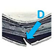 | 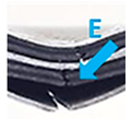 |  |
| FFL/C 5 J | • | • | • | |||
| FFL/C 7.5 J | • | • | • | • | • | |
| FFL/C 10 J | • | • | • | • | • | |
| FFL/C 15 J | • | • | • | • | • | |
| FFL/C 20 J | • | • | • | • | • | • |
| FML/C 5 J | not applicable | • | • | • | ||
| FML/C 7.5 J | n.a. | • | • | • | • | |
| FML/C 10 J | n.a. | • | • | • | • | |
| FML/C 15 J | n.a. | • | • | • | • | |
| FML/C 20 J | n.a. | • | • | • | • | • |
| Sample | Delamination Foam–Composite Interface (A) | Delamination Metal–Composite Interface (B) | Delamination Composite–Composite (C) | Fibre Cracks (D) | Bottom Metal Crack (E) |
|---|---|---|---|---|---|
| View of failure type |  |  |  | 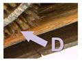 | 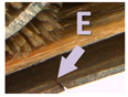 |
| FFL/G 5 J | • | • | • | ||
| FFL/G 7.5 J | • | • | • | ||
| FFL/G 10 J | • | • | • | • | |
| FFL/G 15 J | • | • | • | • | |
| FFL/G 20 J | • | • | • | • | • |
| FML/G 5 J | n.a. | • | • | • | |
| FML/G 7.5 J | n.a. | • | • | • | |
| FML/G 10 J | n.a. | • | • | • | |
| FML/G 15 J | n.a. | • | • | • | |
| FML/G 20 J | n.a. | • | • | • |
Publisher’s Note: MDPI stays neutral with regard to jurisdictional claims in published maps and institutional affiliations. |
© 2021 by the authors. Licensee MDPI, Basel, Switzerland. This article is an open access article distributed under the terms and conditions of the Creative Commons Attribution (CC BY) license (https://creativecommons.org/licenses/by/4.0/).
Share and Cite
Jakubczak, P.; Droździel, M.; Podolak, P.; Pernas-Sánchez, J. Experimental Investigation on the Low Velocity Impact Response of Fibre Foam Metal Laminates. Materials 2021, 14, 5510. https://doi.org/10.3390/ma14195510
Jakubczak P, Droździel M, Podolak P, Pernas-Sánchez J. Experimental Investigation on the Low Velocity Impact Response of Fibre Foam Metal Laminates. Materials. 2021; 14(19):5510. https://doi.org/10.3390/ma14195510
Chicago/Turabian StyleJakubczak, Patryk, Magda Droździel, Piotr Podolak, and Jesus Pernas-Sánchez. 2021. "Experimental Investigation on the Low Velocity Impact Response of Fibre Foam Metal Laminates" Materials 14, no. 19: 5510. https://doi.org/10.3390/ma14195510
APA StyleJakubczak, P., Droździel, M., Podolak, P., & Pernas-Sánchez, J. (2021). Experimental Investigation on the Low Velocity Impact Response of Fibre Foam Metal Laminates. Materials, 14(19), 5510. https://doi.org/10.3390/ma14195510