
Influence of Process Parameters on the Tribological Behavior of PEO Coatings on CP-Titanium 4+ Alloys for Biomedical Applications


Abstract
:1. Introduction
2. Materials and Methods
2.1. Sample Preparation
2.2. Plasma Electrolytic Oxidation
2.3. Characterization
3. Results
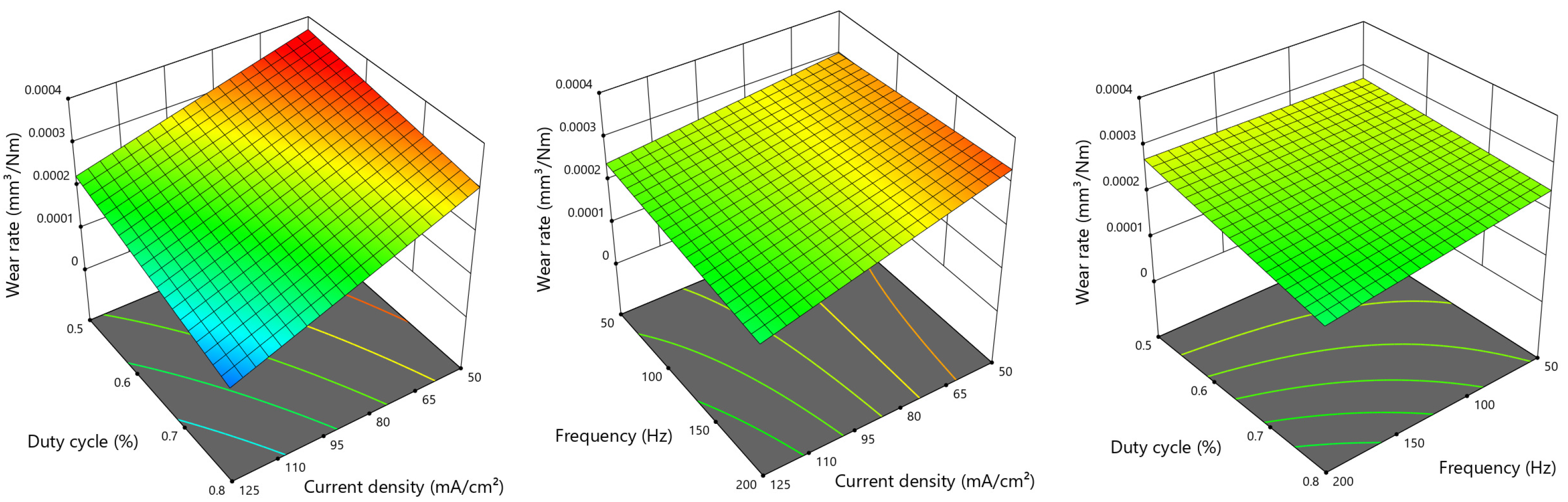
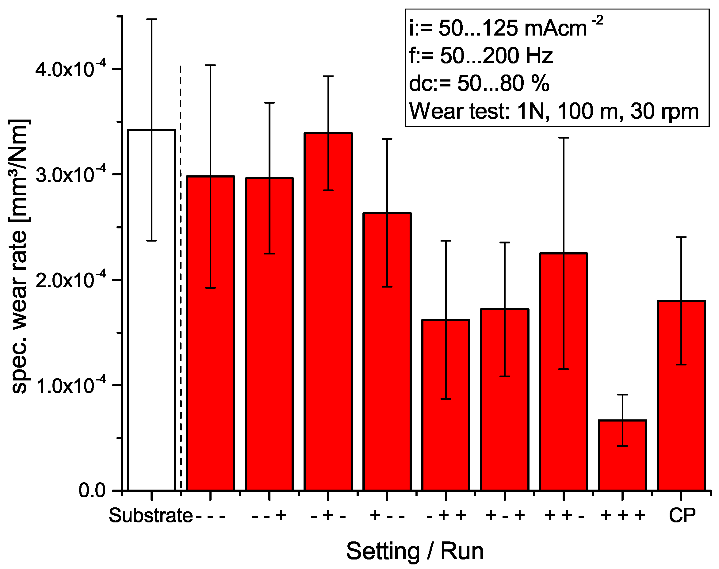
3.1. Wear Test
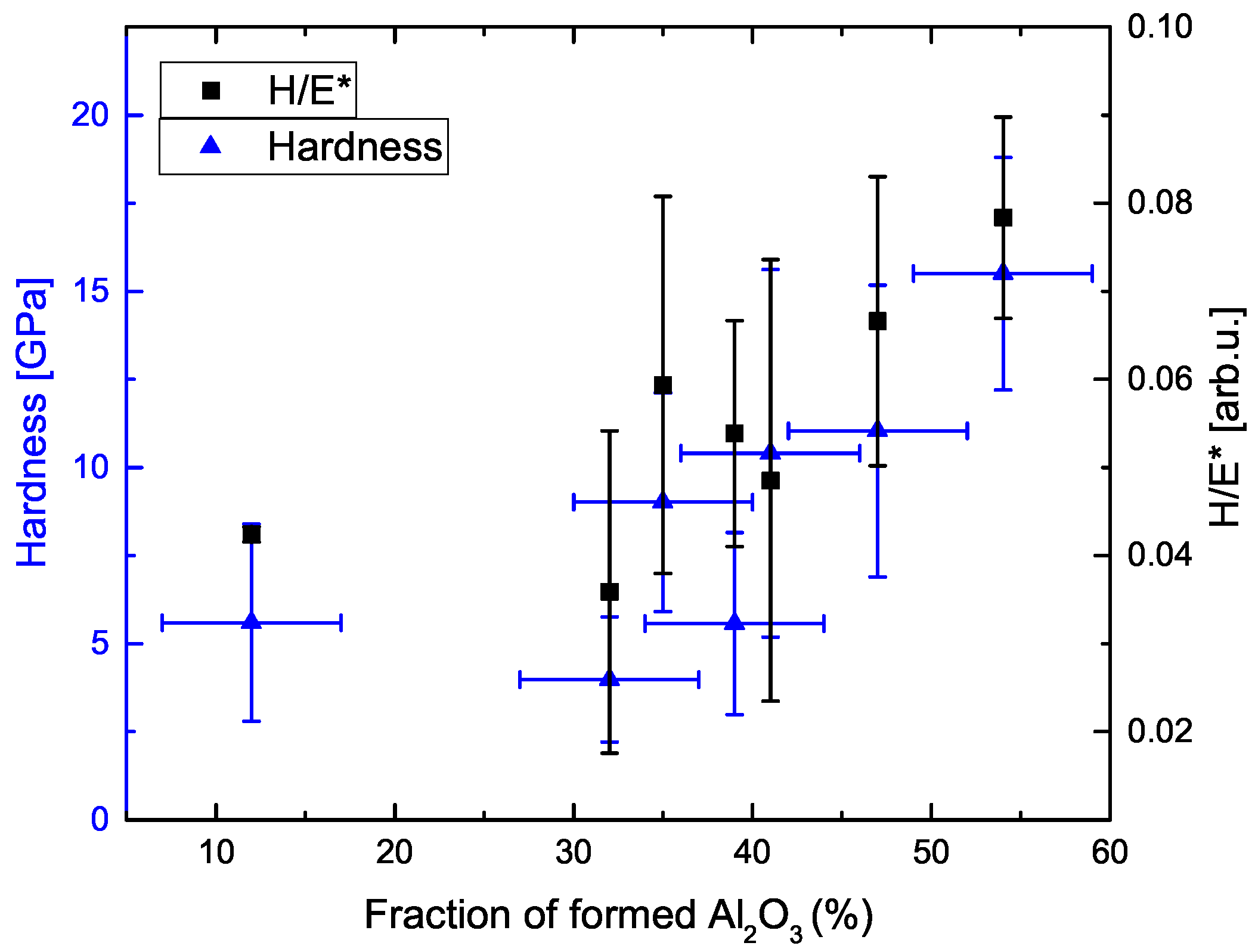
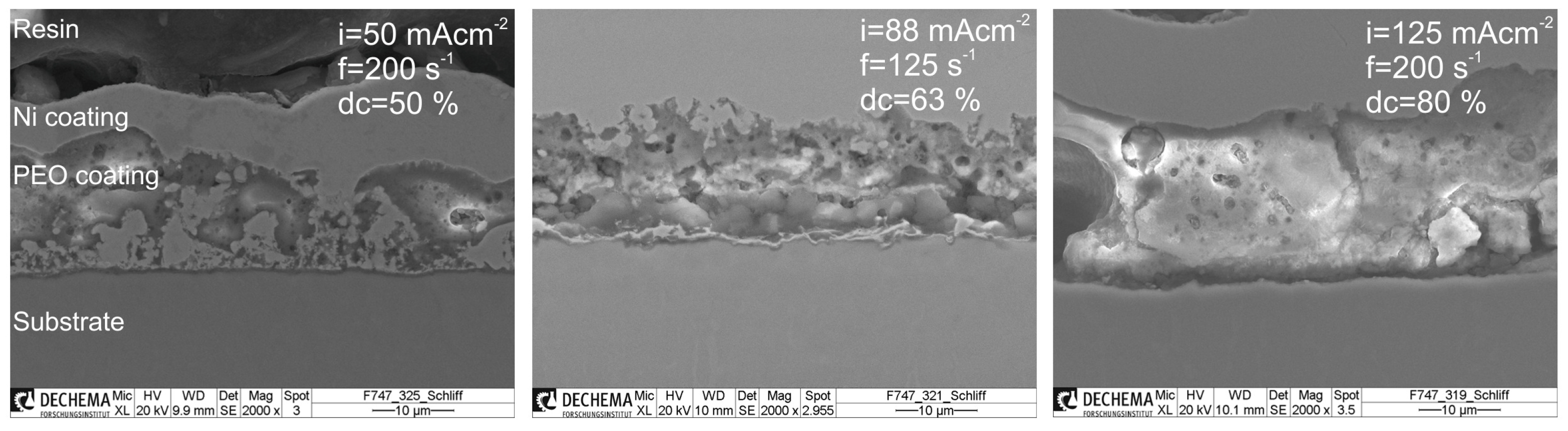
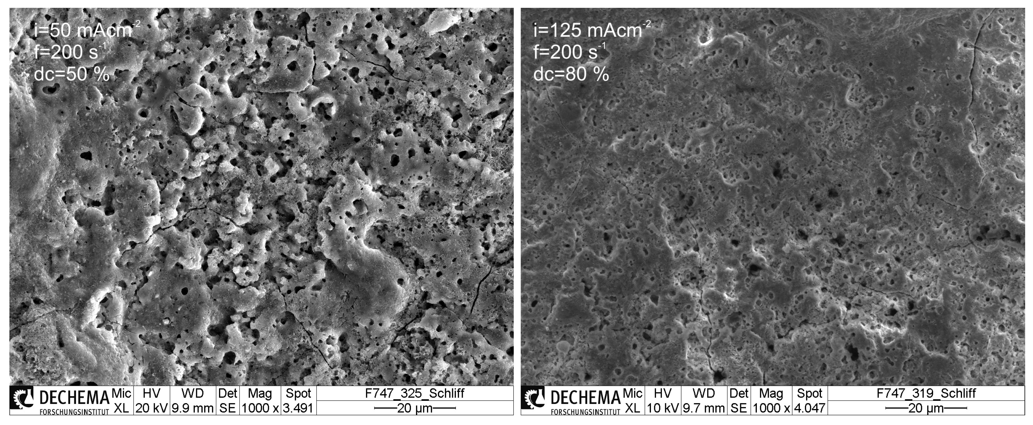
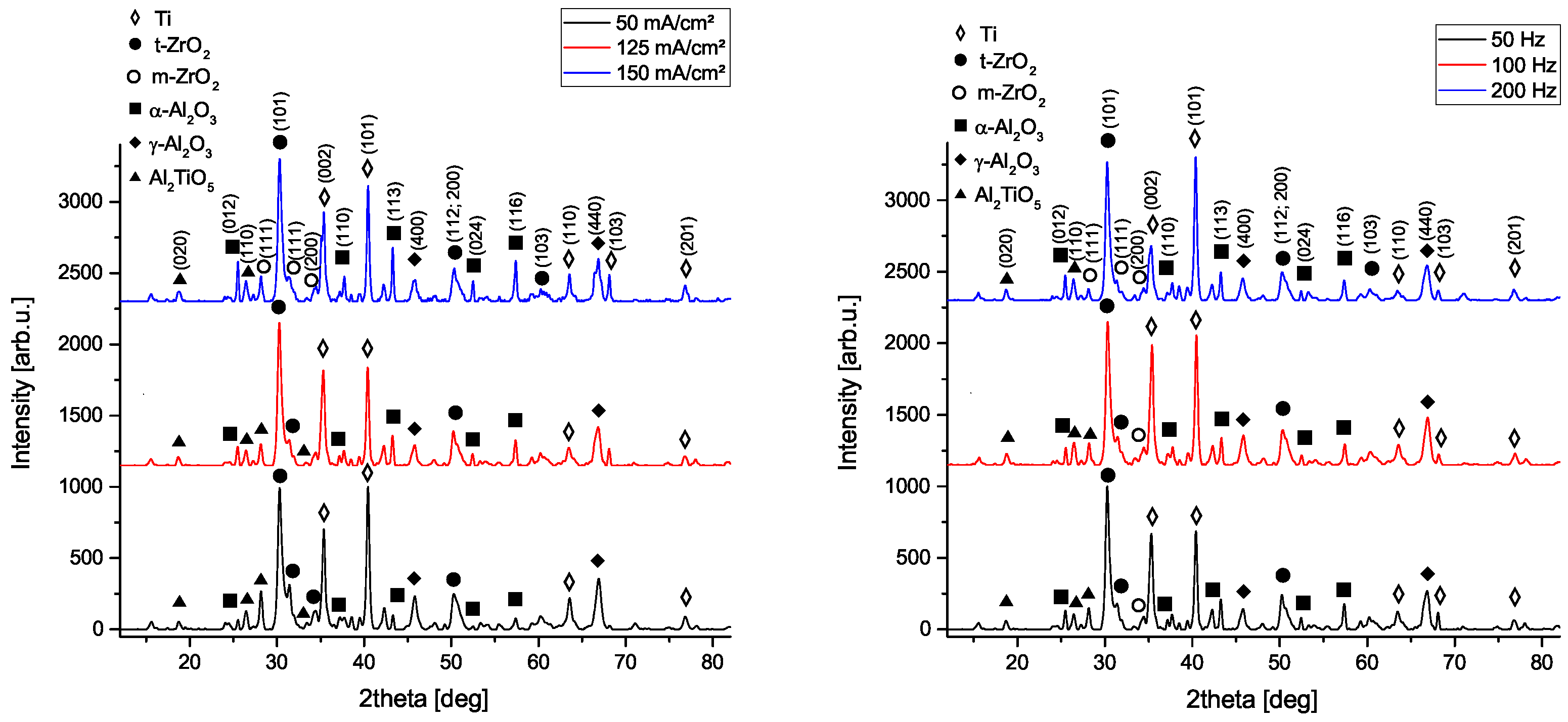
3.2. Morphology and Phase Composition
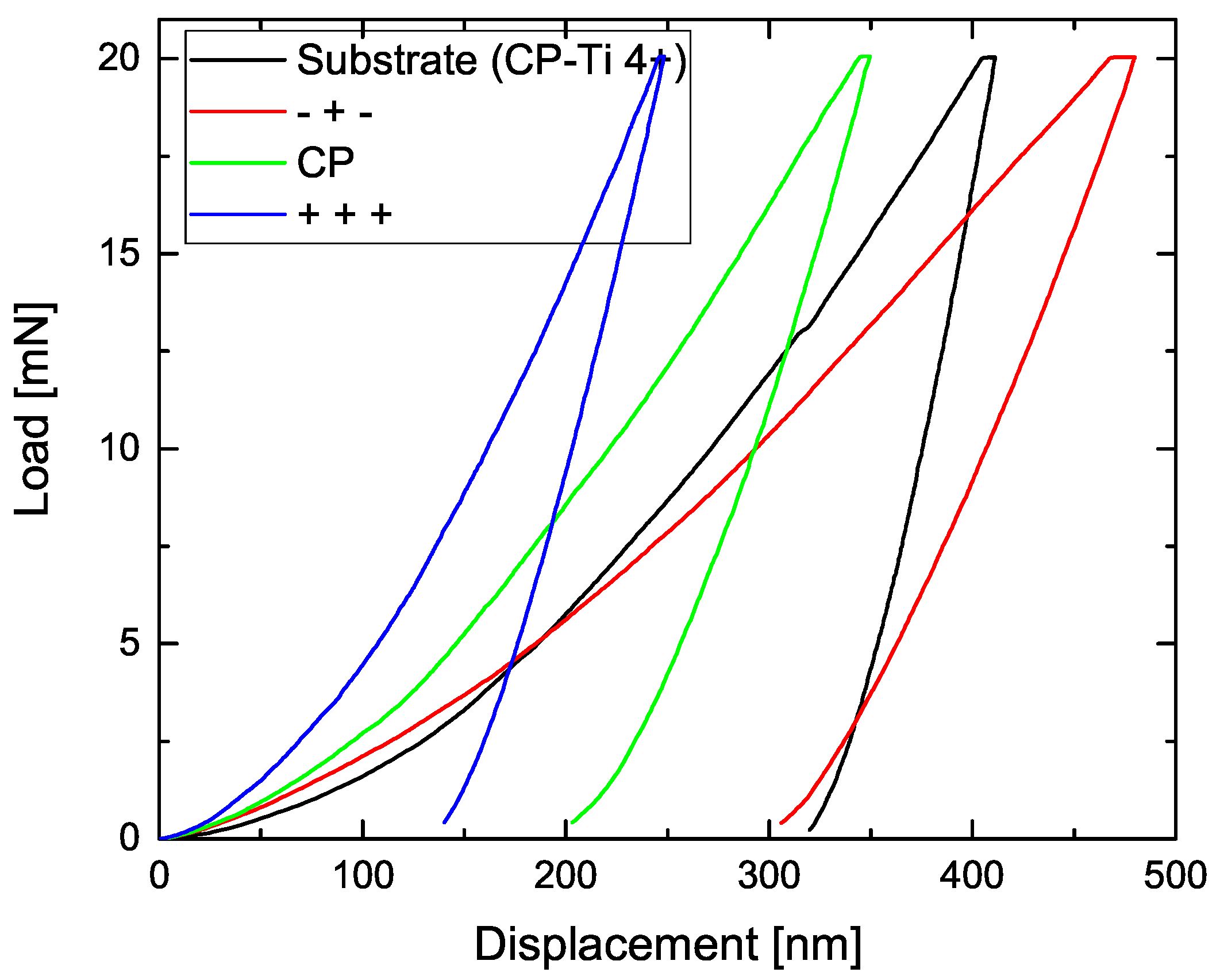
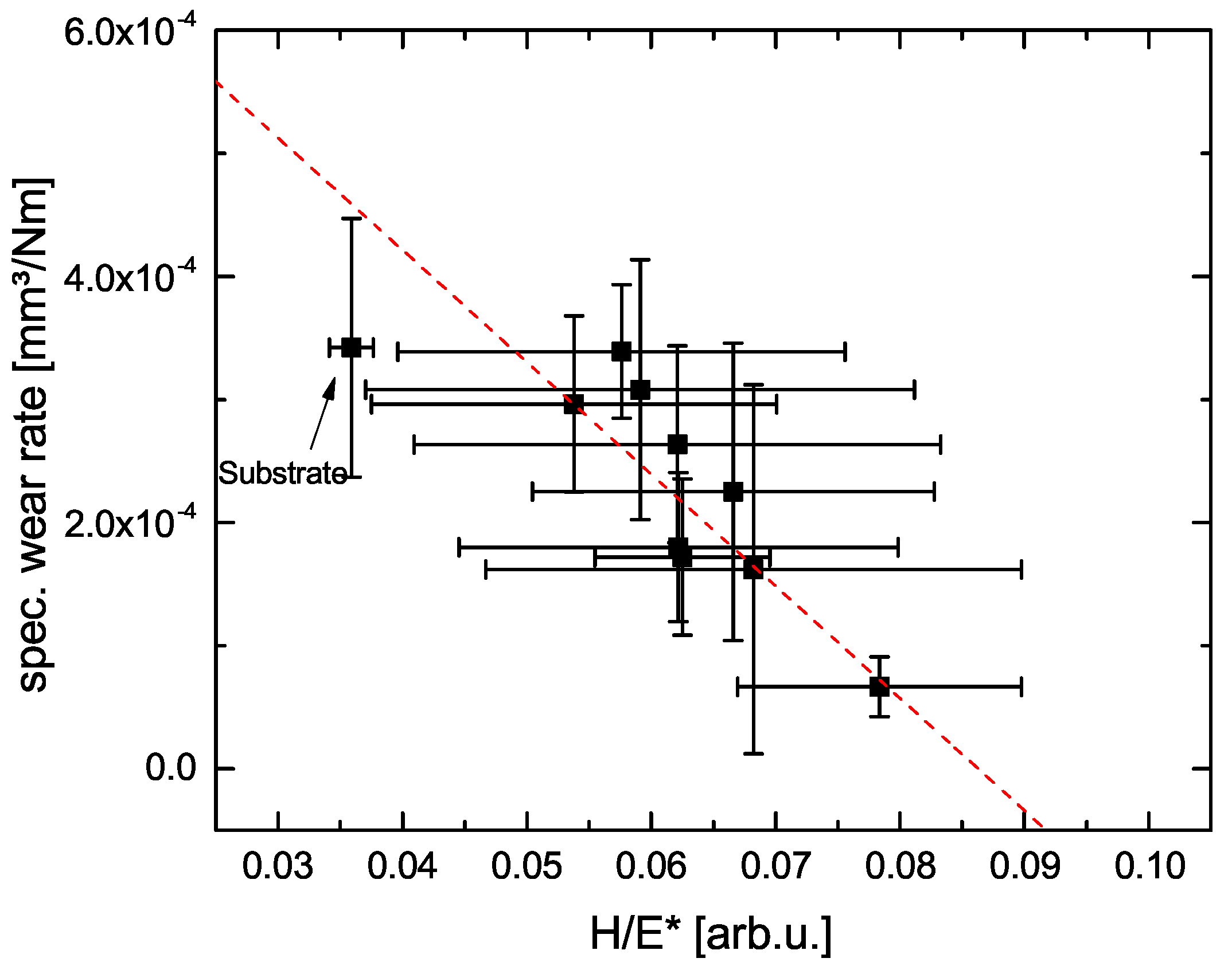
3.3. Nanoindentation Measurements
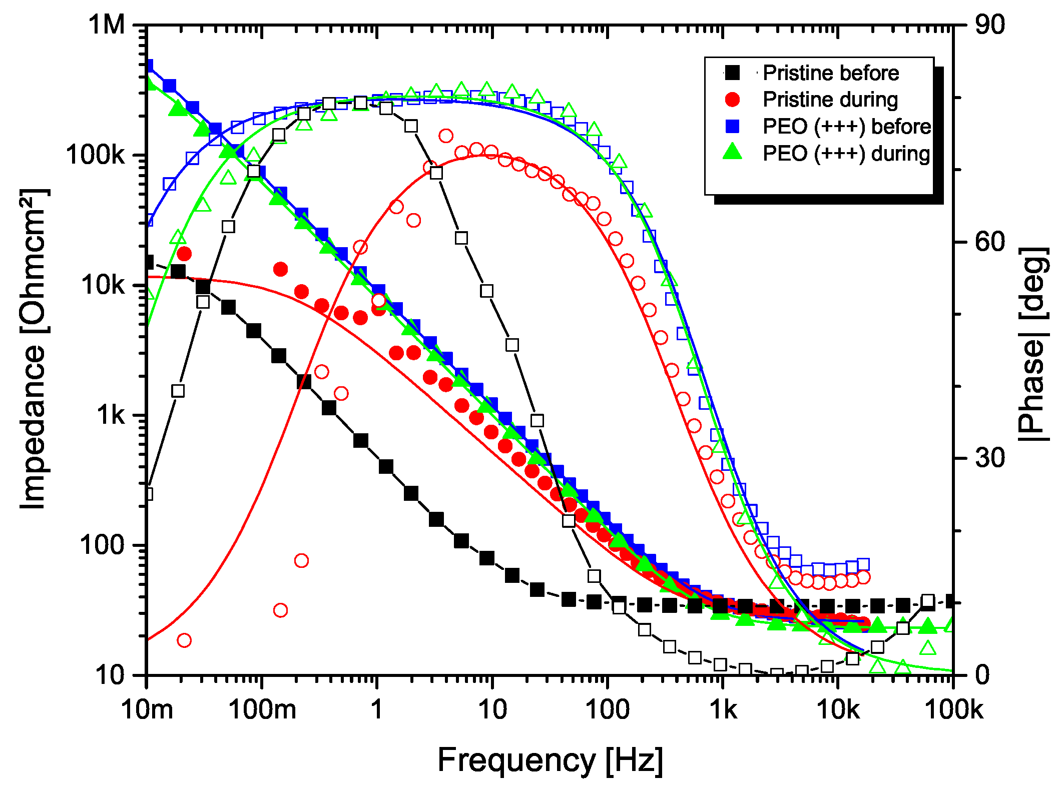
3.4. Electrochemical Impedance Spectroscopy
4. Conclusions
Author Contributions
Funding
Institutional Review Board Statement
Informed Consent Statement
Data Availability Statement
Acknowledgments
Conflicts of Interest
References
- Lütjering, G.; Williams, J.C. Titanium, 2nd ed.; Springer: Berlin, Germany, 2007. [Google Scholar]
- Li, Y.; Yang, C.; Zhao, H.; Qu, S.; Li, X.; Li, Y. New Developments of Ti-Based Alloys for Biomedical Applications. Materials 2014, 7, 1709–1800. [Google Scholar] [CrossRef] [Green Version]
- Breme, J.; Eisenbarth, E.; Biehl, V. Titanium and its Alloys for Medical Applications. In Titanium and Titanium Alloys: Fundamentals and Applications; Peters, M., Leyens, C., Eds.; Wiley VHC: Weinheim, Germany, 2003; pp. 423–451. [Google Scholar]
- Kirmanidou, Y.; Sidira, M.; Drosou, M.-E.; Bennani, V.; Bakopoulou, A.; Tsouknidas, A.; Michailidis, N.; Michalakis, K. New Ti-Alloys and Surface Modifications to Improve the Mechanical Properties and the Biological Response to Orthopedic and Dental Implants: A Review. Biomed Res. Int. 2016, 2908570. [Google Scholar] [CrossRef] [Green Version]
- Barril, S.; Mischler, S.; Landolt, D. Influence of fretting regimes on the tribocorrosion behaviour of Ti6Al4V in 0.9 wt.% sodium chloride solution. Wear 2004, 256, 963–972. [Google Scholar] [CrossRef]
- Souza, J.C.M.; Henriques, M.; Teughels, W.; Ponthiaux, P.; Celis, J.-P.; Rocha, L.A. Wear and Corrosion Interactions on Titanium in Oral Environment: Literature Review. J. Bio Tribo Corros. 2015, 1, 13. [Google Scholar] [CrossRef] [Green Version]
- Di Carlo, E.F.; Bullough, P.G. The Biological Responses to Orthopedic Implants and Their Wear Debris. Clin. Mater. 1992, 9, 235–260. [Google Scholar] [CrossRef]
- Fretwurst, T.; Nelson, K.; Tarnow, D.P.; Wang, H.-L.; Giannobile, W.V. Is Metal Particle Release Associated with Peri-implant Bone Destruction? An Emerging Concept. J. Dent. Res. 2018, 97, 259–265. [Google Scholar] [CrossRef] [PubMed]
- Siemers, C.; Baeker, M.; Brunke, F.; Wolter, D.; Sibum, H. Aluminum- and vanadium-free titanium alloys for application in medical engineering. In Titanium in Medical and Dental Applications; Qian, M., Froes, F., Eds.; Elsevier: Amsterdam, The Netherlands, 2018; pp. 477–492. [Google Scholar]
- Haase, F.; Siemers, C.; Klinge, L.; Lu, C.; Lang, P.; Lederer, S.; König, T.; Rösler, J. Aluminum- and Vanadium-free Titanium Alloys for Medical Applications. MATEC Web Conf. 2020, 321, 05008. [Google Scholar] [CrossRef]
- Lee, H.; Song, M.Y.; Jurng, J.; Park, Y.-K. The synthesis and coating process of TiO2 nanoparticles using CVD process. Powder Technol. 2011, 214, 64–68. [Google Scholar] [CrossRef]
- Cai, J.; Wang, X.; Bai, W.; Zhao, X.; Wang, T.; Tu, J. Bias-graded deposition and tribological properties of Ti-contained a-C gradient composite film on Ti6Al4V alloy. Appl. Surf. Sci. 2013, 279, 450–457. [Google Scholar] [CrossRef]
- Zhang, H.X.; Dai, J.J.; Sun, C.X.; Li, S.Y. Microstructure and wear resistance of TiAlNiSiV high-entropy laser cladding coating on Ti-6Al-4V. J. Mater. Proc. Technol. 2020, 282, 116671. [Google Scholar] [CrossRef]
- Santecchia, E.; Hamouda, A.M.S.; Musharavati, F.; Zalnezhad, E.; Cabibbo, M.; Spigarelli, S. Wear resistance investigation of titanium nitride-based coatings. Ceram. Int. 2015, 41, 10349–10379. [Google Scholar] [CrossRef]
- Hsu, C.-S.; Li, Q. Surface modification of Ti64 through hydrothermal treatment in urea solutions. Mater. Lett. 2018, 216, 299–302. [Google Scholar] [CrossRef]
- Shanmugapriya, P.; Srinivasan, V.; Karthikeyan, B.; Asaithambi, B. Wear Study on sol–gel-coated Ti-6Al-4V Alloy. J. Bio Tribo-Corros. 2020, 6, 129. [Google Scholar] [CrossRef]
- Diamanti, M.V.; Pedeferri, M.P. Effect of anodic oxidation parameters on the titanium oxides formation. Corros. Sci. 2007, 49, 939–948. [Google Scholar] [CrossRef]
- Simka, W.; Sadkowski, A.; Warczak, M.; Iwaniak, A.; Dercz, G.; Michalska, J.; Maciej, A. Characterization of passive films formed on titanium during anodic oxidation. Electrochim. Acta 2011, 56, 8962–8968. [Google Scholar] [CrossRef]
- Yerokhin, A.L.; Nie, X.; Leyland, A.; Matthews, A.; Dowey, S.J. Plasma electrolysis for surface engineering. Surf. Coat. Technol. 1999, 122, 73–93. [Google Scholar] [CrossRef]
- Gupta, P.; Tenhundfeld, G.; Daigle, E.O.; Ryabkov, D. Electrolytic plasma technology: Science and engineering—An overview. Surf. Coat. Technol. 2007, 201, 8746–8760. [Google Scholar] [CrossRef]
- Walsh, F.C.; Low, C.T.J.; Wood, R.J.K.; Stevens, K.T.; Arcer, J.; Poeton, A.R.; Ryder, A. Plasma electrolytic oxidation (PEO) for production of anodised coatings on lightweight metal (Al, Mg, Ti) alloys. Trans. Inst. Met. Finish 2009, 87, 122–135. [Google Scholar] [CrossRef]
- Simchen, F.; Sieber, M.; Kopp, A.; Lampke, T. Introduction to Plasma Electrolytic Oxidation—An Overview of the Process and Applications. Coatings 2020, 10, 628. [Google Scholar] [CrossRef]
- Curran, J.A.; Clyne, T.W. Porosity in plasma electrolytic oxide coatings. Acta Mater. 2006, 54, 1985–1993. [Google Scholar] [CrossRef]
- Galvis, O.A.; Quintero, D.; Castano, J.G.; Liu, H.; Thompson, G.E.; Skeldon, P.; Echeverria, F. Formation of grooved and porous coaings on titanium by plasma electrolytic oxidation in H2SO/H3PO4 electrolytes and effects of coating morphology on adhesive bonding. Surf. Coat. Technol. 2015, 269, 238–249. [Google Scholar] [CrossRef]
- Hussein, R.O.; Northwood, D.O.; Nie, X. The effect of processing parameters and substrate composition on the corrosion resistance of plasma electrolytic oxidation (PEO) coated magnesium alloys. Surf. Coat. Technol. 2013, 237, 357–368. [Google Scholar] [CrossRef]
- Simchen, F.; Sieber, M.; Lampke, T. Electrolyte influence on ignition of plasma electrolytic oxidation processes on light metals. Surf. Coat. Technol. 2017, 315, 205–213. [Google Scholar] [CrossRef]
- Rokosz, K.; Hryniewicz, T.; Dudek, Ł. Phosphate Porous Coatings Enriched with Selected Elements via PEO Treatment on Titanium and Its Alloys: A Review. Materials 2020, 13, 2468. [Google Scholar] [CrossRef] [PubMed]
- Yerokhin, A.L.; Leyland, A.; Matthews, A. Kinetic aspects of aluminium titanate layer formation on titanium alloys by plasma electrolytic oxidation. Appl. Surf. Sci. 2002, 200, 172–184. [Google Scholar] [CrossRef]
- Fattah-alhosseini, F.; Molaei, M.; Babaei, K. The effects of nano- and micro-particles on properties of plasma electrolytic oxidation (PEO) coatings applied on titanium substrates: A review. Surf. Interfaces 2020, 21, 100659. [Google Scholar] [CrossRef]
- Yerokhin, A.L.; Nie, X.; Leyland, A.; Matthews, A. Characterisation of oxide films produced by plasma electrolytic oxidation of a Ti6Al4V alloy. Surf. Coat. Technol. 2000, 130, 195–206. [Google Scholar] [CrossRef]
- Aliasghari, S.; Skeldon, P.; Thompson, G.E. Plasma electrolytic oxidation of titanium in a phosphate/silicate electrolyte and tribological performance of the coatings. Appl. Surf. Sci. 2014, 316, 463–476. [Google Scholar] [CrossRef]
- Tailor, S.; Rakoch, A.G.; Gladkova, A.A.; Truong, P.V.; Strekalina, D.M.; Sourkoni, G.; Manjunath, S.Y.; Takagi, T. Kinetic features of wear-resistant coating growth by plasma electrolytic oxidation. Surf. Innov. 2018, 6, 150–158. [Google Scholar] [CrossRef]
- Shokoufar, M.; Dehghanian, C.; Baradaran, A. Preparation of ceramic coating on Ti substrate by plasma electrolytic oxidation in different electrolytes and evaluation of its corrosion resistance. Appl. Surf. Sci. 2011, 257, 2617–2624. [Google Scholar] [CrossRef]
- Nabavi, H.F.; Aliofkhazraei, M.; Rouhaghdam, A.S. Morphology and corrosion resistance of hybrid plasma electrolytic oxidation on CP-Ti. Surf. Coat. Technol. 2017, 322, 59–69. [Google Scholar] [CrossRef]
- Yu, J.-M.; Kim, H.-J.; Ahn, S.-G.; Choe, H.-C. Plasma electrolytic oxidation of Ti-6Al-4V alloy in electrolytes containing bone formation ions. Appl. Surf. Sci. 2020, 513, 145776. [Google Scholar] [CrossRef]
- Echeverry-Rendón, M.; Galvis, O.; Quintero Giraldo, D.; Pavón, J.; López-Lacomba, J.L.; Jiménez-Piqué, E.; Anglada, M.; Robledo, S.M.; Castano, J.G.; Echeverría, F. Osseointegration improvement by plasma electrolytic oxidation of modified titanium alloys surfaces. J. Mater. Sci. Mater. Med. 2015, 26, 72. [Google Scholar] [CrossRef] [PubMed] [Green Version]
- Lederer, S.; Sankaran, S.; Smith, T.; Fuerbeth, W. Formation of bioactive hydroxyapatite-containing titania coatings on CP-Ti 4+ alloy generated by plasma electrolytic oxidation. Surf. Coat. Technol. 2019, 363, 66–74. [Google Scholar] [CrossRef]
- Oliver, W.C.; Pharr, G.M. An improved technique for determining hardness and elastic modulus using load and displacement sensing indentation experiments. J. Mater. Res. 1992, 7, 1564–1583. [Google Scholar] [CrossRef]
- Egorkin, V.S.; Gnedenkov, S.V.; Sinebryukhov, S.L.; Vyaliya, I.E.; Gnedenkov, A.S.; Chizhikov, R.G. Increasing thickness and protective properties of PEO-coatings on aluminum. Surf. Coat. Technol. 2018, 334, 29–42. [Google Scholar] [CrossRef]
- Han, X.; Zhang, Z.; Thrush, S.J.; Barber, G.C.; Qu, H. Ionic liquid stabilized nanoparticle additive in a steel-ceramic contact for extreme pressure application. Wear 2020, 452–453, 203264. [Google Scholar] [CrossRef]
- Tsetsekou, A. A comparison study of tialite ceramics doped with various oxide materials and tialite–mullite composites: Microstructural, thermal and mechanical properties. J. Eur. Ceram. 2005, 25, 335–348. [Google Scholar] [CrossRef]
- Han, X.; Zhang, Z.; Hou, J.; Barber, G.C.; Qiu, F. Tribological behavior of shot peenned/austemperd AISI 5160 steel. Tribol. Int. 2020, 145, 106197. [Google Scholar] [CrossRef]
- Ao, N.; Liu, D.; Zhang, X.; Liu, C. Enhanced fatigue performance of modified plasma electrolytic oxidation coated Ti-6Al-4V alloy: Effect of residual stress and gradient nanostructure. Appl. Surf. Sci. 2019, 489, 595–607. [Google Scholar] [CrossRef]
- Leyland, A.; Matthews, A. On the significance of the H/E ratio in wear control: A nanocomposite coating approach to optimised tribological behaviour. Wear 2000, 246, 1–11. [Google Scholar] [CrossRef]
- Gonzalez, J.; Mirza-Rosca, J. Study of the corrosion behavior of titanium and some of its alloys for biomedical and dental implant applications. J. Electroanal. Chem. 1999, 471, 109–115. [Google Scholar] [CrossRef]
- Bai, Y.J.; Wang, Y.B.; Chen, Y.; Deng, F.; Zheng, Y.F.; Wei, S.C. Comparative study on the corrosion behavior of Ti–Nb and TMA alloys for dental application in various artificial solutions. Mater. Sci. Eng. C 2011, 31, 702–711. [Google Scholar] [CrossRef]
- Ponthiaux, P.; Wenger, F.; Drees, D.; Celis, J.P. Electrochemical techniques for studying tribocorrosion processes. Wear 2004, 256, 459–468. [Google Scholar] [CrossRef]


| Element | Ti | O | Fe | C | Si |
|---|---|---|---|---|---|
| Composition [wt.%] | Bal. | 0.44 | 0.50 | 0.08 | 0.50 |
| Configuration | Current Density i | Frequency f | Duty Cycle dc |
|---|---|---|---|
| i/f/dc | [mAcm] | [Hz] | [%] |
| 50 | 50 | 50 | |
| 50 | 50 | 80 | |
| 50 | 250 | 50 | |
| 125 | 50 | 50 | |
| 50 | 250 | 80 | |
| 125 | 50 | 80 | |
| 125 | 250 | 50 | |
| 125 | 250 | 80 | |
| CP | 88 | 125 | 63 |
| Substance | Concentration | pH | Conductivity |
|---|---|---|---|
| [gL] | [mScm] | ||
| NaOH | 2 | ||
| NaAlO | 40 | 13 | 47 |
| m-ZrO | 4 |
| DoE Setting | Coating Thickness | av. Roughness R | Porosity |
|---|---|---|---|
| [i/f/dc] | [m] | [m] | % |
| 14.5 ± 3.6 | 2.8 | 24.6 ± 8.7 | |
| 15.5 ± 4.4 | 2.7 | 11.3 ± 1.2 | |
| 15.5 ± 4.0 | 2.6 | 16.7 ± 4.8 | |
| 15.0 ± 4.9 | 4.6 | 14.1 ± 1.0 | |
| 15.3 ± 3.3 | 3.5 | 14.6 ± 3.2 | |
| 12.1 ± 3.6 | 5.0 | 6.5 ± 1.9 | |
| 13.2 ± 2.5 | 4.8 | 7.0 ± 2.9 | |
| 17.5 ± 3.5 | 3.5 | 4.0 ± 2.3 | |
| CP | 15.2 ± 4.7 | 4.1 | 9.1 ± 2.8 |
| DoE Setting | Hardness | Red. Young’s Modulus | Plasticity Index |
|---|---|---|---|
| [i/f/dc] | [GPa] | [GPa] | arb.u. |
| Substrate | 4.5 ± 0.2 | 129 ± 9 | |
| 5.8 ± 2.6 | 101 ± 67 | 0.62 ± 0.31 | |
| 5.9 ± 2.9 | 110 ± 22 | 0.62 ± 0.08 | |
| 4.0 ± 2.8 | 105 ± 37 | 0.48 ± 0.09 | |
| 9.0 ± 3.1 | 145 ± 26 | 0.61 ± 0.13 | |
| 10.4 ± 5.2 | 152 ± 30 | 0.63 ± 0.15 | |
| 9.5 ± 2.9 | 155 ± 39 | 0.62 ± 0.08 | |
| 11.0 ± 4.1 | 166 ± 43 | 0.57 ± 0.10 | |
| 15.5 ± 3.3 | 198 ± 28 | 0.78 ± 0.03 | |
| CP | 10.2 ± 3.2 | 168 ± 29 | 0.59 ± 0.14 |
Publisher’s Note: MDPI stays neutral with regard to jurisdictional claims in published maps and institutional affiliations. |
© 2021 by the authors. Licensee MDPI, Basel, Switzerland. This article is an open access article distributed under the terms and conditions of the Creative Commons Attribution (CC BY) license (https://creativecommons.org/licenses/by/4.0/).
Share and Cite
Lederer, S.; Arat, S.; Fuerbeth, W. Influence of Process Parameters on the Tribological Behavior of PEO Coatings on CP-Titanium 4+ Alloys for Biomedical Applications. Materials 2021, 14, 5364. https://doi.org/10.3390/ma14185364
Lederer S, Arat S, Fuerbeth W. Influence of Process Parameters on the Tribological Behavior of PEO Coatings on CP-Titanium 4+ Alloys for Biomedical Applications. Materials. 2021; 14(18):5364. https://doi.org/10.3390/ma14185364
Chicago/Turabian StyleLederer, Stephan, Serkan Arat, and Wolfram Fuerbeth. 2021. "Influence of Process Parameters on the Tribological Behavior of PEO Coatings on CP-Titanium 4+ Alloys for Biomedical Applications" Materials 14, no. 18: 5364. https://doi.org/10.3390/ma14185364
APA StyleLederer, S., Arat, S., & Fuerbeth, W. (2021). Influence of Process Parameters on the Tribological Behavior of PEO Coatings on CP-Titanium 4+ Alloys for Biomedical Applications. Materials, 14(18), 5364. https://doi.org/10.3390/ma14185364