
Full-Scale Use of Microwave Heating in Construction of Longitudinal Joints and Crack Healing in Asphalt Pavements

 ,
,  ,
, 
Abstract
:1. Introduction
- skewed profiling (60°), formed by the roller compactor (or paver) equipped with the edge forming plate,
- vertical profiling, formed with the use of knife installed on roller compactor; formed after compaction of asphalt layer when it cools down below compaction temperature,
- different wedge compactors for forming the longitudinal joints,
- a different strategy of asphalt paving and compaction order, in particular, the following:
- ◦
- use of adequate thickness of asphalt layer, which cannot be thinner than cold lane after compaction, because it may lead to under compaction issue,
- ◦
- use of the paver controlled with an averaging ski, helping to synchronize layers thickness,
- ◦
- establishing of steel or rubber roller compactor passes over the joint,
- ◦
- the finish of compaction work before reaching layer minimum compaction temperature.
- additional tack-coat application over the cold lane edge (asphalt emulsion, hot asphalt or bituminous paste),
- additional sealing material, e.g., bituminous tape, bituminous paste or bituminous sealant.
- reheating of cold lane edge using induction heating [11],
- reheating of cold lane edge using microwave applicator.
2. Materials and Methods
2.1. Testing Program
- Phase 1––the laboratory evaluation of dielectric properties of asphalt materials and constituting materials (presented in [43]),
- Phase 2––the laboratory evaluation of dielectric heating on the properties of asphalt, aggregate and bitumen,
- Phase 3––the real-scale experiment of the use of dielectric heating during construction and repair process of the asphalt pavement.
2.2. Design of Experiment, Scope of Research, Test Section
- to evaluate if microwave-assisted joint construction technique has advantages over traditional methods of joint construction,
- to evaluate the effectiveness of crack repair using microwave heating technique,
- to consider if dielectric heating causes more severe damage to the bituminous binder than traditional heating.
2.3. Materials
2.4. Test Specimens and Test Methods
2.5. Microwave Applicator
2.6. Microwave Assisted Processes
3. Results
3.1. General
3.2. Longitudinal Joints
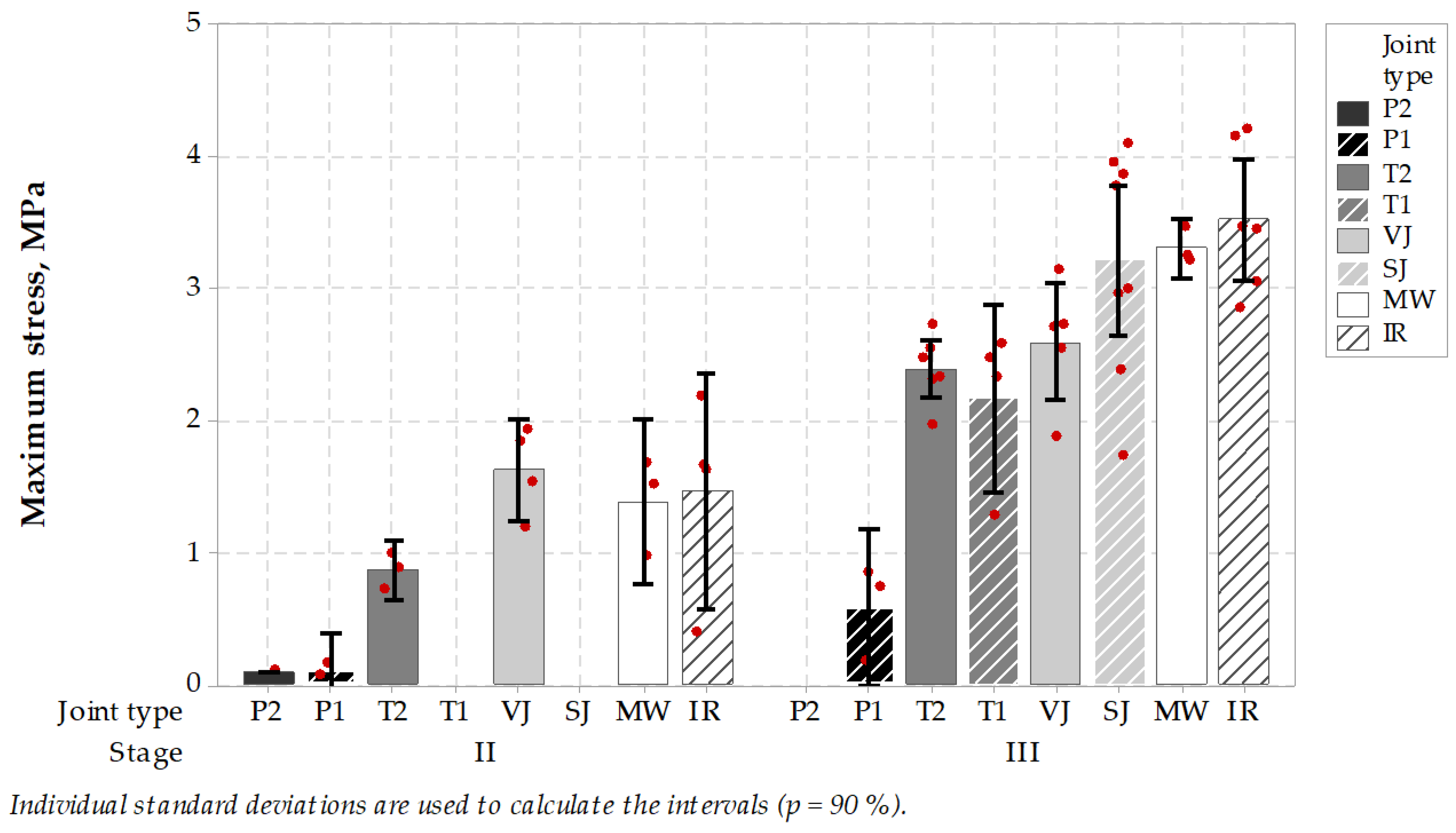
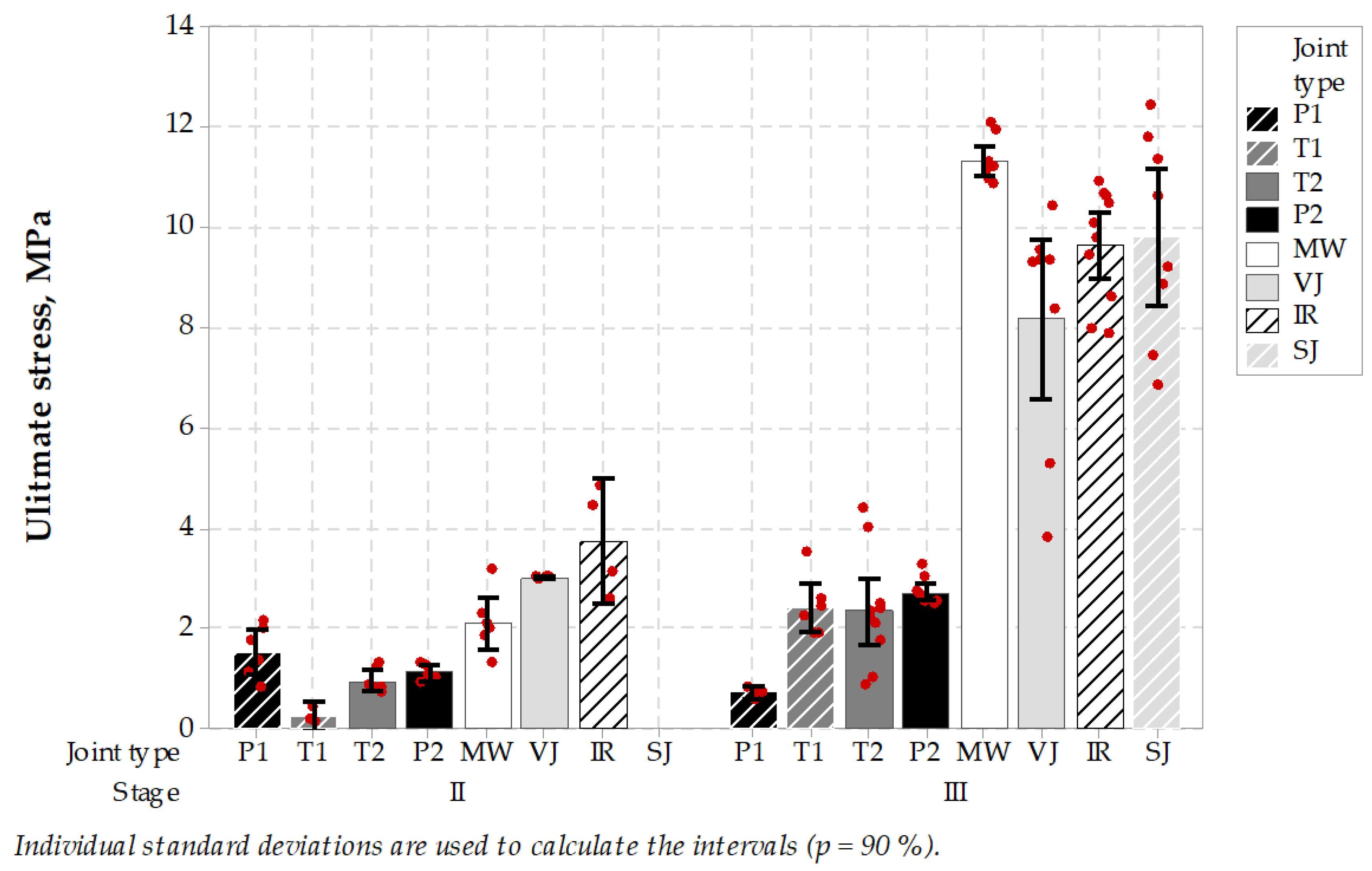
3.2.1. Low-Temperature Cracking TSRST
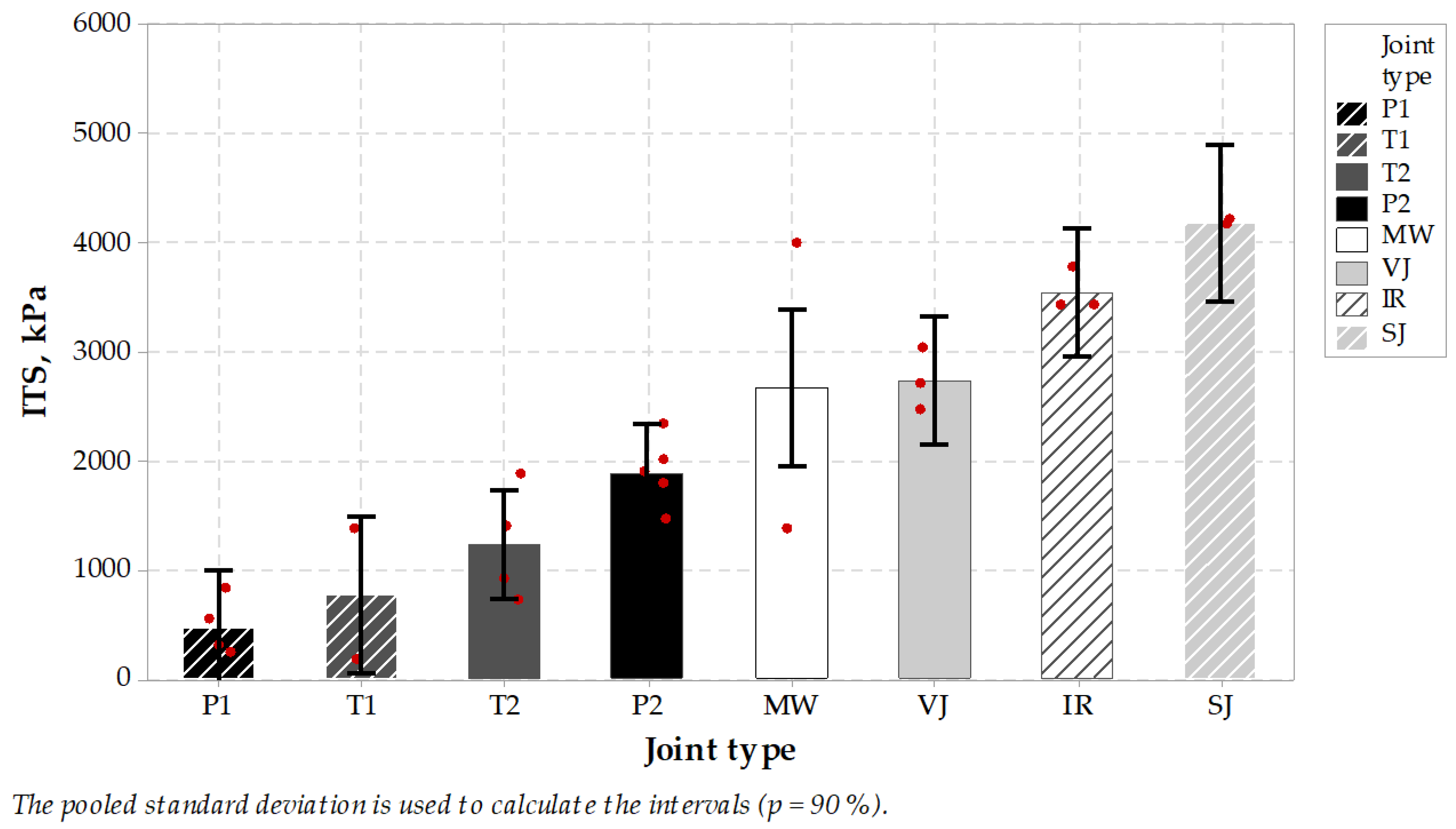
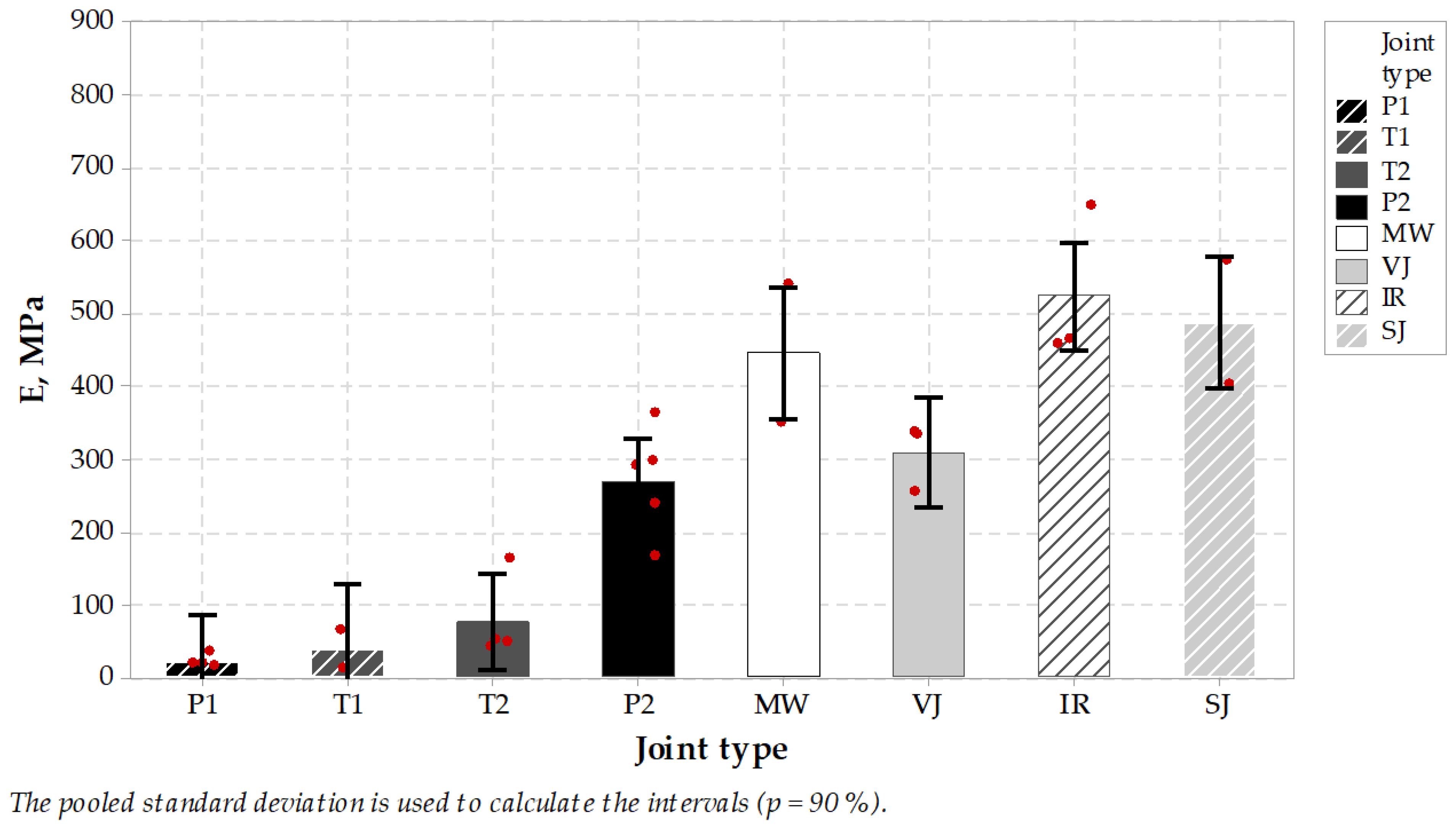
3.2.2. Indirect Tensile Strength ITS
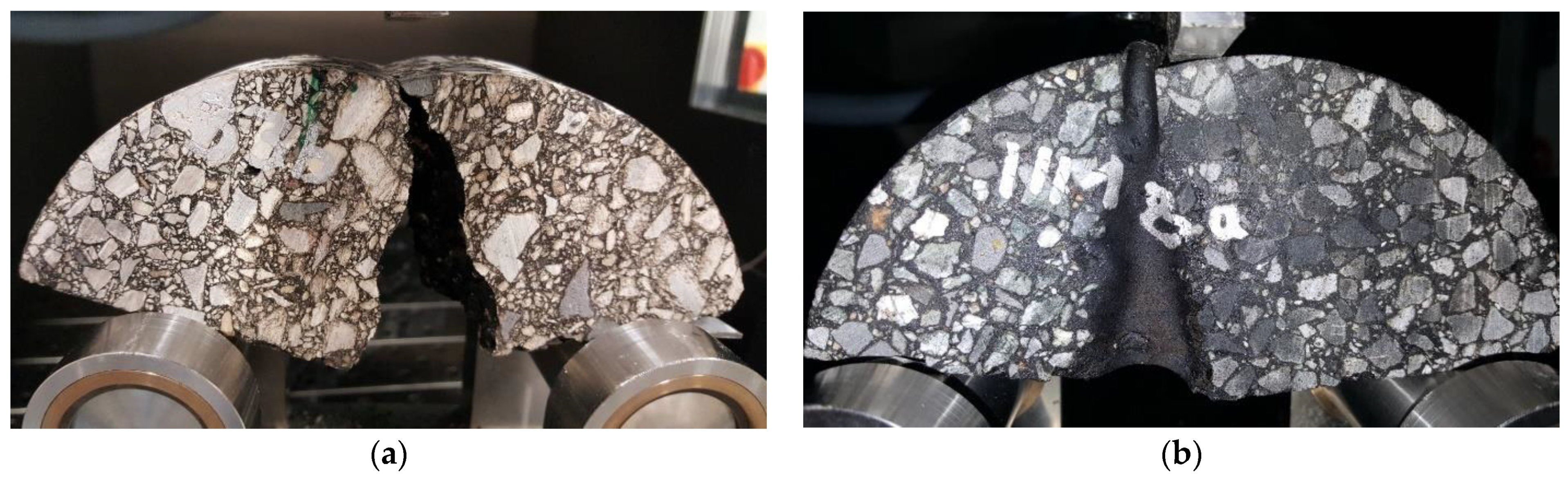
3.2.3. Semi-Circular Bending SCB
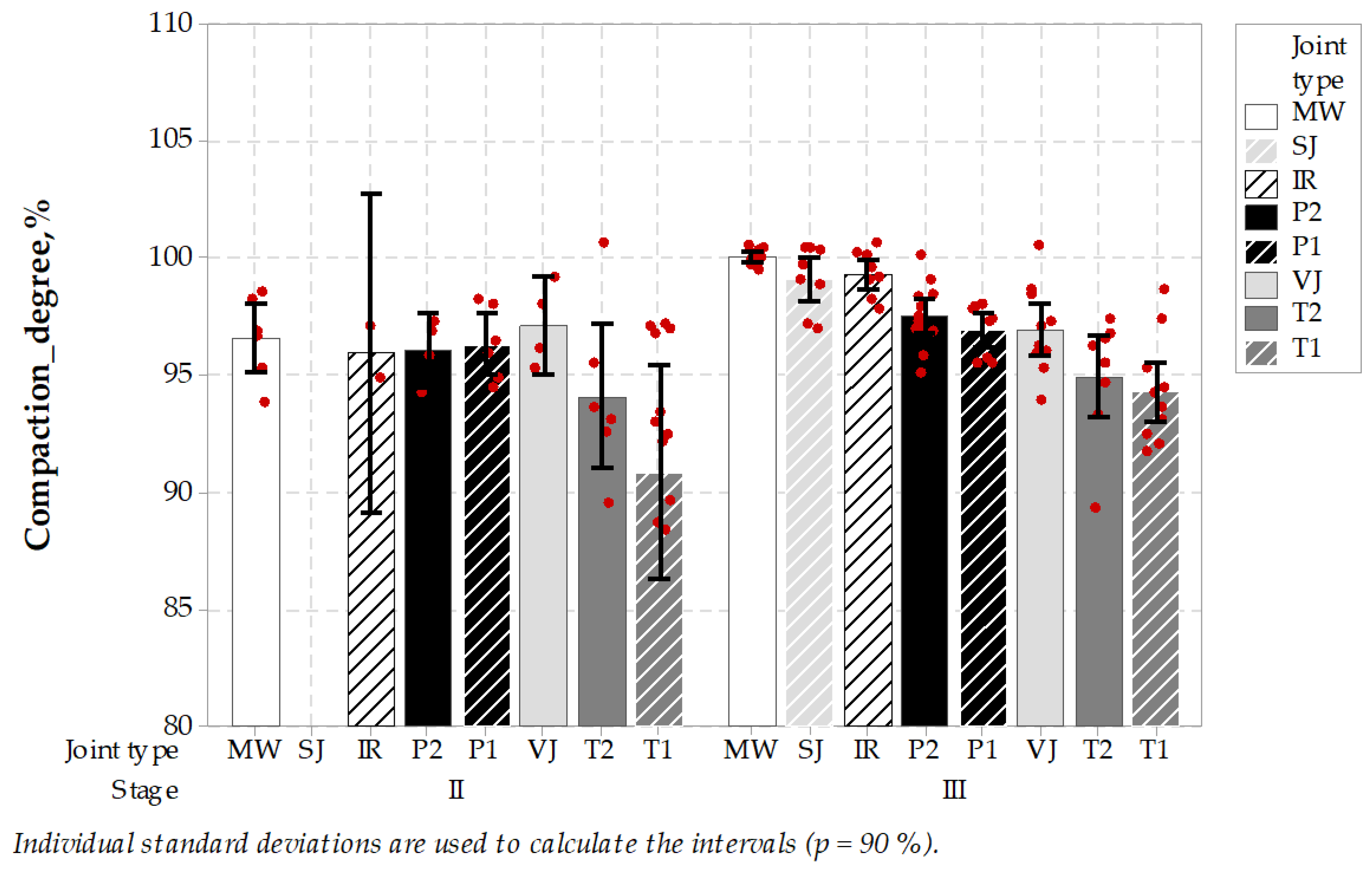
3.2.4. Density Measurements
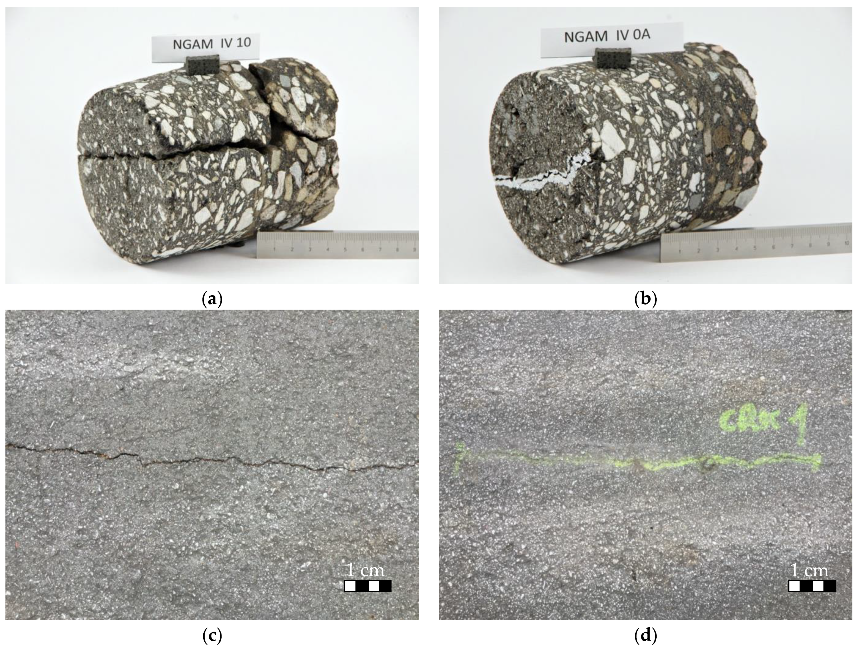
3.3. Crack Repair
3.3.1. General
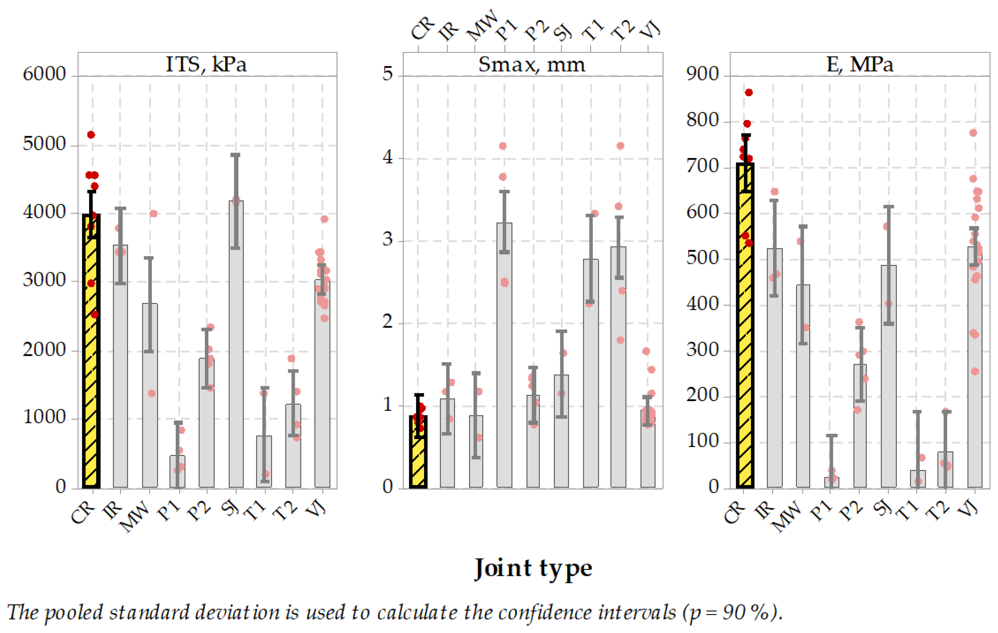
3.3.2. Indirect Tensile Strength ITS
3.3.3. Semi-Circular Bending SCB
3.3.4. Summary of the Crack Repair Process
3.4. Bitumen
4. Discussion
5. Conclusions
- MW joints were durable in TSRST test, no negative influence on low-temperature cracking was concluded; even though the maximum stresses were higher than in case of sealed joints, crack temperature level was still on a satisfactory level,
- MW joints were in the middle class for the ITS test, while E modulus presented the highest level in the test set,
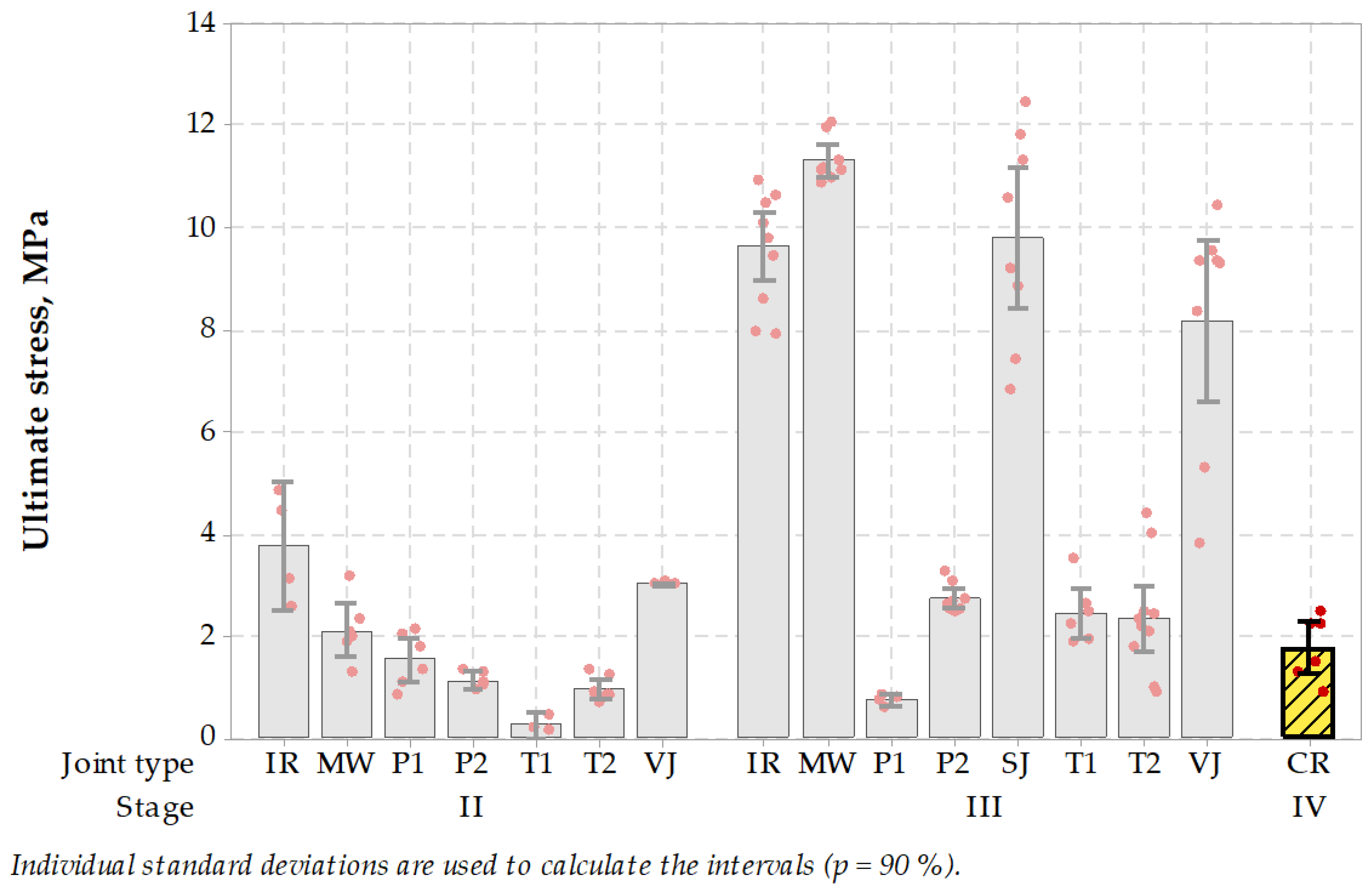
- MW joints were significantly in the best class of the ultimate stress test results as regards the wearing course (stage III); it showed an overall significant advantage over material type joints while being the best in the class of the treated and untreated joints,
- the density measurements showed most important MW joint technique advantage over other tested techniques, presenting the highest average value and lowest range of single results; the difference was not significant, but one of the reasons was high standard deviations achieved in case of the other jointing techniques,
- MW crack repair technique brought good results should be observed in a longer period; what is important, the repair process can be repeated according to needs,
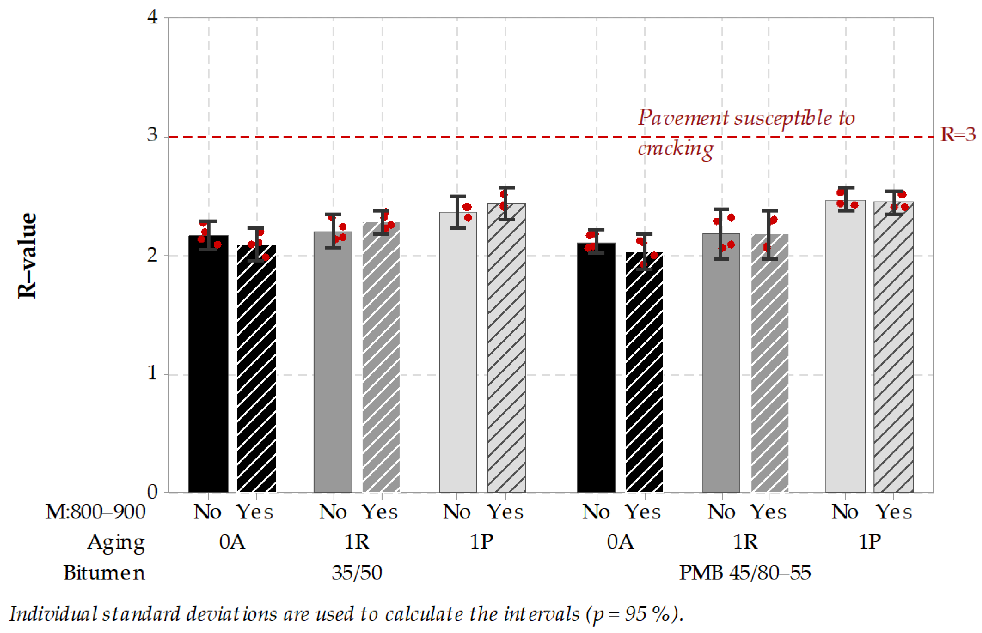
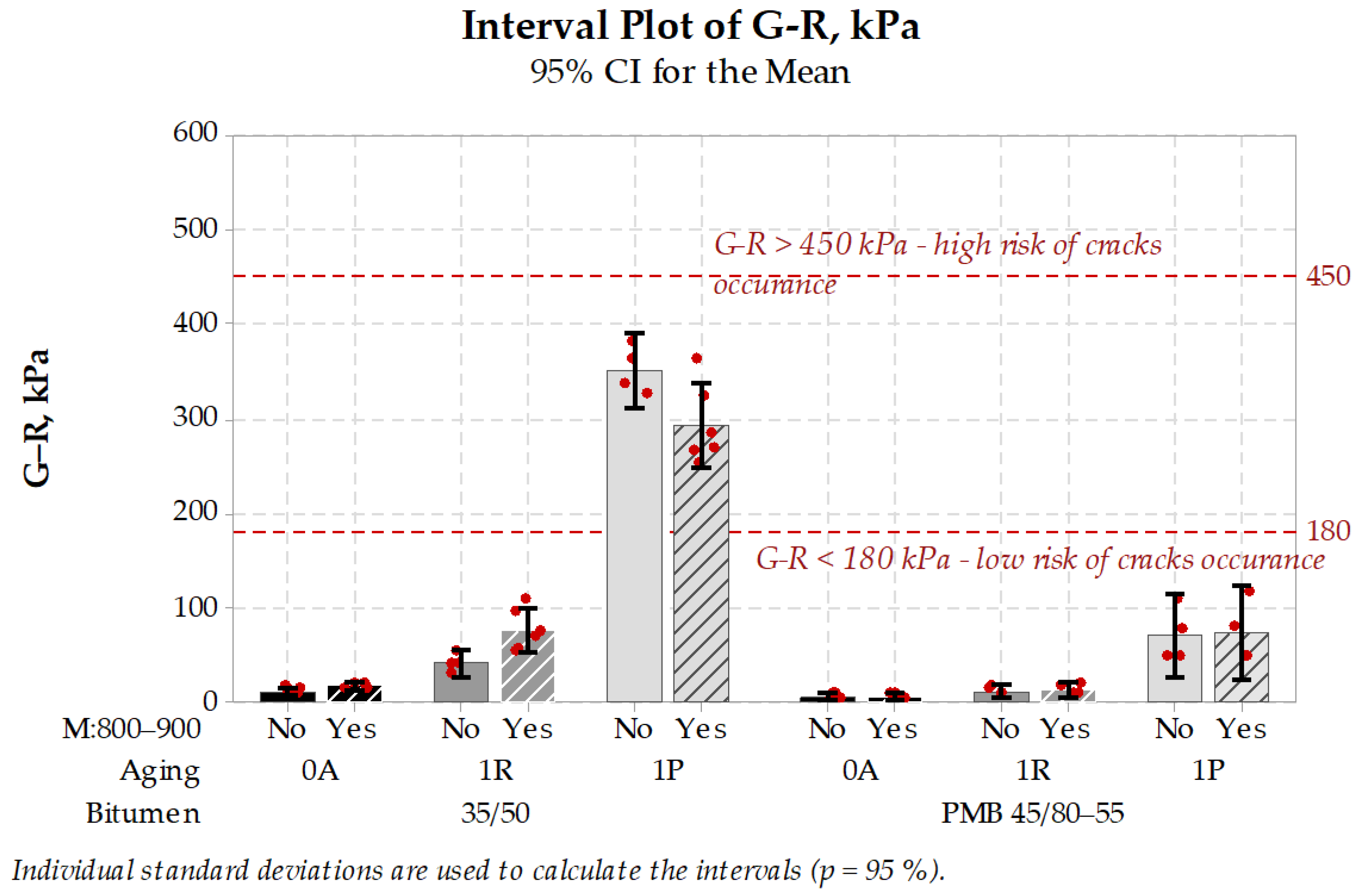
- Bitumen tests did not bring any negative conclusions as regards bitumen properties and their predicted influence on cracking susceptibility of asphalt pavement.
Author Contributions
Funding
Institutional Review Board Statement
Informed Consent Statement
Data Availability Statement
Acknowledgments
Conflicts of Interest
Appendix A

| Properties (Standard) | Basalt 0/2 | Basalt 2/5 | Basalt 5/8 | Basalt 8/11 | Basalt 11/16 |
|---|---|---|---|---|---|
| Aggregate size d/D (mm), EN 933-1 | 0/2 | 2/5 | 5/8 | 8/11 | 11/16 |
| Aggregate distribution category (mm), EN 933-1 | Gc85 | Gc90/10 | Gc90/10 | Gc90/10 | Gc90/10 |
| Aggregate tolerance category (mm), EN 933-1 | GTC20 | G25/15 | G25/15 | G25/15 | G25/15 |
| Aggregate apparent density (Mg/m3), EN 1097-6 | ρa 3.00 | ρa 3.01 | ρa 3.02 | ρa 3.01 | ρa 3.01 |
| Agg. oven dried density (Mg/m3), EN 1097-6 | ρrd 2.84 | ρrd 2.89 | ρrd 2.90 | ρrd 2.89 | ρrd 2.89 |
| Agg. saturated surface dried dens. (Mg/m3), EN 1097-6 | ρssd 2.90 | ρssd 2.93 | ρssd 2.94 | ρssd 2.93 | ρssd 2.93 |
| Shape index (mass %), EN 933-4 | − | SI15 | SI15 | SI15 | SI15 |
| Flakiness index (mass %), EN 933-3 | − | FI10 | FI10 | FI10 | FI10 |
| Fines content (mass %), EN 933-1 | 16 | 2 | 2 | 2 | 2 |
| Fines quality (methylene blue value), EN 933-9 | MBf10 | − | − | − | − |
| Bitumen affinity (rotating bottle test, %) | − | 6 h–90% | 6 h–90% | 6 h–90% | 6 h–90% |
| EN 12697-11 | 24 h–70% | 24 h–70% | 24 h–70% | 24 h–70% | |
| Percentage of crushed and broken surface (mass %), | − | C100/0 | C100/0 | C100/0 | C100/0 |
| EN 933-5 | |||||
| Los-Angeles index, EN 1097-2 | − | 15 | 15 | 15 | 15 |
| Polishing stone value, EN 1097-8 | − | 48 | 48 | 48 | 48 |
| Aggregate abrasion value, EN 1097-9 | − | 10 | 10 | 10 | 10 |
| Micro-Deval index, EN 1097-1 | − | 15 | 15 | 15 | 15 |
| Resistance to thermal shock, EN 1367-5 | − | I%1.5 | I%1.5 | I%1.5 | I%1.5 |
| − | VLA5 | VLA5 | VLA5 | VLA5 | |
| Water absorption 24 h, EN 1097-6 | 1.9 | 1.3 | 1.3 | 1.3 | 1.3 |
| Resistance to freezing and thawing, EN 1367-1 | − | 0.2 | 0.2 | 0.2 | 0.2 |
| Sand angularity index, EN 933-6 | Ecs38 | − | − | − | − |
| “Sonnenbrand” of basalt, EN 1367-3 | − | SBLA | SBLA | SBLA | SBLA |
| Properties (Standard) | Gabbro 0/2 | Gabbro 2/5 | Gabbro 4/8 |
|---|---|---|---|
| Aggregate size d/D (mm), EN 933-1 | 0/2 | 2/5 | 4/8 |
| Aggregate distribution category (mm), EN 933-1 | Gc85 | Gc90/15 | Gc90/10 |
| Aggregate tolerance category (mm), EN 933-1 | GTC10 | G25/15 | G25/15 |
| Aggregate apparent density (Mg/m3), EN 1097-6 | ρa 2.93 | ρa 2.99 | ρa 2.98 |
| Agg. oven dried density (Mg/m3), EN 1097-6 | ρrd 2.83 | ρrd 2.95 | ρrd 2.96 |
| Agg. saturated surface dried dens. (Mg/m3), EN 1097-6 | ρssd 2.87 | ρssd 2.97 | ρssd 2.97 |
| Shape index (mass %), EN 933-4 | − | SI20 | SI15 |
| Flakiness index (mass %), EN 933-3 | − | FI20 | FI15 |
| Fines content (mass %), EN 933-1 | 10 | 1 | 1 |
| Fines quality (methylene blue value), EN 933-9 | MBf10 | − | − |
| Bitumen affinity (rotating bottle test, %) | − | 6 h–62% | 6 h–62% |
| EN 12697-11 | 24 h–18% | 24 h–18% | |
| Percentage of crushed and broken surface (mass %), | − | C100/0 | C100/0 |
| EN 933-5 | |||
| Los-Angeles index, EN 1097-2 | − | 15 | 15 |
| Polishing stone value, EN 1097-8 | − | 55 | 58 |
| Aggregate abrasion value, EN 1097-9 | − | 10 | 10 |
| Micro-Deval index, EN 1097-1 | − | 10 | 10 |
| Resistance to thermal shock, EN 1367-5 | − | I%0.8 | I%0.8 |
| VLA3.4 | VLA3.4 | ||
| Water absorption 24 h, EN 1097-6 | 1.0 | 1.0 | 1.0 |
| Resistance to freezing and thawing, EN 1367-1 | − | F1 | F1 |
| Sand angularity index, EN 933-6 | Ecs38 | − | − |
| Properties (Standard) | Limestone 0/2 | Limestone 0/4 | Limestone 2/8 | Limestone 8/16 |
|---|---|---|---|---|
| Aggregate size d/D (mm), EN 933-1 | 0/2 | 0/4 | 2/8 | 8/16 |
| Aggregate distribution category (mm), EN 933-1 | GF85 | GA90/15 | Gc90/10 | Gc90/20 |
| Aggregate tolerance category (mm), EN 933-1 | GTC20 | GTC20 | G20/17.5 | G20/15 |
| Aggregate apparent density (Mg/m3), EN 1097-6 | ρa 2.71 | ρa 2.71 | ρa 2.71 | ρa 2.71 |
| Agg. oven dried density (Mg/m3), EN 1097-6 | ρrd 2.66 | ρrd 2.64 | ρrd 2.68 | ρrd 2.69 |
| Agg. saturated surface dried dens. (Mg/m3), EN 1097-6 | ρssd 2.68 | ρssd 2.67 | ρssd 2.69 | ρssd 2.70 |
| Shape index (mass %), EN 933-4 | − | − | SI25 | SI25 |
| Flakiness index (mass %), EN 933-3 | − | − | FI25 | FI25 |
| Fines content (mass %), EN 933-1 | 3 | 16 | 2 | 2 |
| Fines quality (methylene blue value), EN 933-9 | − | MBf10 | − | − |
| Bitumen affinity (rotating bottle test, %) | − | − | 6 h:65–90% | 6 h:65–90% |
| EN 12697-11 | 24 h:40–80% | 24 h:40–80% | ||
| Percentage of crushed and broken surface (mass %), | − | − | C100/0 | C100/0 |
| EN 933-5 | ||||
| Los-Angeles index, EN 1097-2 | − | − | 30 | 30 |
| Polishing stone value, EN 1097-8 | − | − | 44 | 44 |
| Aggregate abrasion value, EN 1097-9 | − | − | 15 | 15 |
| Micro-Deval index, EN 1097-1 | − | − | 25 | 25 |
| Resistance to thermal shock, EN 1367-5 | − | − | I%0.2–1.0 | I%0.2–1.0 |
| VLA1–4 | VLA1–4 | |||
| Water absorption 24 h, EN 1097-6 | 1.0 | 1.0 | 1.0 | 1.0 |
| Resistance to freezing and thawing, EN 1367-1 | − | − | F1 | F1 |
| Sand angularity index, EN 933-6 | Ecs30 | Ecs30 | − | − |
| Mix Designation | AC 8 G | SMA 8 B | AC 16 W | AC 16 B |
|---|---|---|---|---|
| Aggregate type | 100% gabbro | 100% basalt | 100% limestone | 100% basalt |
| Dielectric constant ε′ | 5.76–6.04 | 6.45–6.74 | 6.51–7.01 | 6.60–7.22 |
| Dielectric loss factor ε″ | 0.031–0.044 | 0.293–0.329 | 0.033–0.035 | 0.338–0.391 |
| Bitumen Characteristic | PMB 45/80−55 | 35/50 |
|---|---|---|
| Penetration 25 °C, 0.1× mm, EN 1426 | 54 | 42 |
| Softening point, °C, EN 1427 | 61.0 | 53.8 |
| Breaking point, °C, EN 12593 | −24 | −16 |
References
- Buncher, M.; Rosenberger, C. Best Practices for Constructing and Specifying HMA Longitudinal Joints; Asphalt Institute: Lexington, KY, USA, 2012. [Google Scholar]
- Chen, C.; Williams, R.C.; Ahmed EI., T.; Lee, H.D.; Schram, S. Quality control/quality assurance testing for longitudinal joint density and segregation of asphalt mixtures. Constr. Build. Mater. 2013, 47, 80–85. [Google Scholar] [CrossRef] [Green Version]
- Zofka, A.; Braham, A. Comparison of Low-Temperature Field Performance and Laboratory Testing of 10 Test Sections in the Midwestern United States. Transp. Res. Rec. J. Transp. Res. Board 2009, 2127, 107–114. [Google Scholar] [CrossRef]
- Montepara, A.; Santagata, E.; Tosi, G. Photochemical degradation of pure bitumen by U.V. radiation. In Proceedings of the Eurasphalt & Eurobitume Congress, Strasbourg, France, 7–10 May 1996; European Asphalt Pavement Association & Eurobitume: Strasbourg, France, 1996; p. 13. [Google Scholar]
- Maliszewski, M.; Zofka, A.; Maliszewska, D.; Sybilski, D. Asphalt Mixture Sensitivity to Water and Frost. In 8th RILEM International Symposium on Testing and Characterization of Sustainable and Innovative Bituminous Materials; Springer: Berlin/Heidelberg, Germany, 2016; Volume 11, pp. 177–188. [Google Scholar]
- Mieczkowski, P. Securing cracks and expansion joints in the technology of hot-poured road repair compounds. Part 1. Classification and properties of compounds. Izolacje 2012, 17, 78–85. [Google Scholar]
- Kandhal, P.; Mallick, R. Study of Longitudinal-Joint Construction Techniques in Hot-Mix Asphalt Pavements. Transp. Res. Rec. J. Transp. Res. Board 1996, 1543, 106–112. [Google Scholar] [CrossRef]
- Zofka, A.; Mahoney, J.; Zinke, S.; Shaffer, G. Comparison of Butt and Notched Wedge Longitudinal Joints Constructed in Connecticut. In Proceedings of the ASCE’s 2008 Airfield & Highway Pavements Conference, Bellevue, WA, USA, 15–18 October 2008; pp. 258–262. [Google Scholar]
- Williams, S.G. HMA Longitudinal Joint Evaluation and Construction Final Report; University of Arkansas: Fayetteville, AR, USA, 2011. [Google Scholar]
- Kieswetter, B. Solving the Biggest Problem in Asphalt Paving. Available online: http://www.heavyequipmentguide.ca/article/24591/solving-the-biggest-problem-in-asphalt-paving (accessed on 8 April 2017).
- Bueno, M.; Arraigada, M.; Partl, M.N. Induction heating technology for improving compaction of asphalt joints. Int. J. Pavement Eng. 2020, 21, 1532–1540. [Google Scholar] [CrossRef]
- Akpinar, M.V.; Hossain, M. Longitudinal Joint Construction for Hot Mix Asphalt Pavements; Kansas State University: Manhattan, KS, USA, 2004. [Google Scholar]
- Zanko, L. Evaluate and Develop Innovative Pavement Repair and Patching: Taconite-based Repair Options; University of Minnesota Duluth: Duluth, MN, USA, 2016. [Google Scholar]
- Maliszewski, M. Zastosowanie Mikrofal Podczas Wykonywania i Naprawy Nawierzchni Asfaltowej (Application of Microwave Technology for Construction and Repair of Asphalt Pavements, PL), 1st ed.; Kiljan-Walerzak, J., Ed.; Instytut Badawczy Dróg i Mostów: Warszawa, Poland, 2020; ISBN 978-83-89252-34-0. [Google Scholar]
- Maxwell, J.C. A Dynamical Theory of the Electromagnetic Field. Philos. Trans. R. Soc. Lond. 1865, 155, 459–512. [Google Scholar] [CrossRef]
- Reitz, J.R.; Milford, F.J. Foundations of Electromagnetic Theory; Addison-Wesley: Reading, MA, USA, 1960. [Google Scholar]
- Jackson, J.D. Classical Electrodynamics; John Wiley & Sons: New York, NY, USA, 1962; ISBN 0-471-43131-1. [Google Scholar]
- Mingos, D.M.P. Theoretical Aspects of Microwave Dielectric Heating. In Microwave Assisted Organic Synthesis; Blackwell Publishing Ltd.: Oxford, UK, 2009; pp. 1–22. ISBN 9781405175906. [Google Scholar]
- Jones, D.; Lelyveld, T.; Mavrofidis, S. Microwave heating applications in environmental engineering—A review. Resour. Conserv. 2002, 34, 75–90. [Google Scholar] [CrossRef]
- Angoy, A.; Brianceau, S.; Chabrier, F.; Ginisty, P.; Jomaa, W.; Rochas, J.-F.; Sommier, A.; Valat, M. Microwave technology for food applications. Green Food Process. Tech. 2019, 455–498. [Google Scholar] [CrossRef]
- Gulisano, F.; Gallego, J. Microwave heating of asphalt paving materials: Principles, current status and next steps. Constr. Build. Mater. 2021, 278, 121993. [Google Scholar] [CrossRef]
- Al-Ohaly, A.A.; Terrel, R.L. Effect of microwave heating on adhesion and moisture damage of asphalt mixtures. Transp. Res. Rec. 1988, 1171, 27–36. [Google Scholar]
- Terrel, R.L.; Hicks, R.G.; Ca, C.; Hall, L. Viability of Hot In-Place Recycling as a Pavement Preservation Strategy Report Number: CP2C-2008-106; California Pavement Preservation Center, CSU: Chico, CA, USA, 2008. [Google Scholar]
- Zhu, S.Q.; Shi, J.F.; Hao, F. Research on the Pavement Performance of Recycled Asphalt Mixture Processed by Microwave. Adv. Mater. Res. 2010, 148–149, 987–993. [Google Scholar] [CrossRef]
- Mitchell, M.R.; Link, R.E.; Wang, H.; Hao, P.; Xue, L. Laboratory Evaluation of Microwave Heating Method for Hot In-Place Recycling. J. Test. Eval. 2011, 39, 103122. [Google Scholar] [CrossRef]
- Benedetto, A.; Calvi, A. A pilot study on microwave heating for production and recycling of road pavement materials. Constr. Build. Mater. 2013, 44, 351–359. [Google Scholar] [CrossRef]
- Gallego, J.; del Val, M.A.; Contreras, V.; Páez, A. Heating asphalt mixtures with microwaves to promote self-healing. Constr. Build. Mater. 2013, 42, 1–4. [Google Scholar] [CrossRef]
- Norambuena-Contreras, J.; Gonzalez-Torre, I. Influence of the Microwave Heating Time on the Self-Healing Properties of Asphalt Mixtures. Appl. Sci. 2017, 7, 1076. [Google Scholar] [CrossRef] [Green Version]
- Norambuena-Contreras, J.; Garcia, A. Self-healing of asphalt mixture by microwave and induction heating. Mater. Des. 2016, 106, 404–414. [Google Scholar] [CrossRef]
- Sun, Y.; Wu, S.; Liu, Q.; Li, B.; Fang, H.; Ye, Q. The healing properties of asphalt mixtures suffered moisture damage. Constr. Build. Mater. 2016, 127, 418–424. [Google Scholar] [CrossRef]
- Liu, Q.; Chen, C.; Li, B.; Sun, Y.; Li, H. Heating Characteristics and Induced Healing Efficiencies of Asphalt Mixture via Induction and Microwave Heating. Materials 2018, 11, 913. [Google Scholar] [CrossRef] [Green Version]
- Bhattacharya, M.; Basak, T.; Senagala, R. A comprehensive theoretical analysis for the effect of microwave heating on the progress of a first order endothermic reaction. Chem. Eng. Sci. 2011, 66, 5832–5851. [Google Scholar] [CrossRef]
- Wang, H.; Zhang, Y.; Zhang, Y.; Feng, S.; Lu, G.; Cao, L. Laboratory and Numerical Investigation of Microwave Heating Properties of Asphalt Mixture. Materials 2019, 12, 146. [Google Scholar] [CrossRef] [Green Version]
- Sun, Y.H.; Liu, Q.T.; Wu, S.P.; Shang, F. Microwave Heating of Steel Slag Asphalt Mixture. Key Eng. Mater. 2014, 599, 193–197. [Google Scholar] [CrossRef]
- Wang, Z.; Xu, C.; Wang, S.; Gao, J.; Ai, T. Utilization of magnetite tailings as aggregates in asphalt mixtures. Constr. Build. Mater. 2016, 114, 392–399. [Google Scholar] [CrossRef]
- Liu, W.; Miao, P.; Wang, S. Heating characteristics of microwave-absorbing asphalt mixture. In Proceedings of the Green Building, Environment, Energy and Civil Engineering, Hong Kong, China, 26–27 April 2016; Kao, J., Sung, W., Eds.; Taylor & Francis Group: London, UK, 2016; pp. 163–167. [Google Scholar]
- Lou, B.; Liu, Z.; Sha, A.; Jia, M.; Li, Y. Microwave Absorption Ability of Steel Slag and Road Performance of Asphalt Mixtures Incorporating Steel Slag. Materials 2020, 13, 663. [Google Scholar] [CrossRef] [Green Version]
- Pérez, I.; Agzenai, Y.; Pozuelo, J.; Sanz, J.; Baselga, J.; García, A.; Pérez, V. Self-healing of asphalt mixes, containing conductive modified bitumen, using microwave heating. In Proceedings of the 6th Eurasphalt & Eurobitume Congress, Prague, Czech Republic, 1–3 June 2016; Czech Technical University in Prague: Prague, Czech Republic, 2016. [Google Scholar]
- Norambuena-Contreras, J.; Serpell, R.; Valdés Vidal, G.; González, A.; Schlangen, E. Effect of fibres addition on the physical and mechanical properties of asphalt mixtures with crack-healing purposes by microwave radiation. Constr. Build. Mater. 2016, 127, 369–382. [Google Scholar] [CrossRef]
- Wang, Z.; Dai, Q.; Porter, D.; You, Z. Investigation of microwave healing performance of electrically conductive carbon fiber modified asphalt mixture beams. Constr. Build. Mater. 2016, 126, 1012–1019. [Google Scholar] [CrossRef]
- Gallego, J.; Del Val, M.A.; Contreras, V.; Páez, A. Use of additives to improve the capacity of bituminous mixtures to be heated by means of microwaves. Mater. Constr. 2017, 67, 110. [Google Scholar] [CrossRef] [Green Version]
- Zhu, X.; Fan, Y.; Yu, Y.; Gilabert, F.A. Crack propagation and microwave healing of Ferrite-filled asphalt mixes based on image correlation observations. Constr. Build. Mater. 2020, 262, 119978. [Google Scholar] [CrossRef]
- Salski, B.; Olszewska-Placha, M.; Karpisz, T.; Rudnicki, J.; Gwarek, W.; Maliszewski, M.; Zofka, A.; Skulski, J. Microwave Applicator for Thermal Treatment of Bituminous Surfaces. IEEE Trans. Microw. Theory Tech. 2017, 65, 3419–3427. [Google Scholar] [CrossRef]
- Maliszewski, M.; Maliszewska, D.; Zofka, A.; Bańkowski, W.; Gajewski, M.; Horodecka, R.; Mirski, K.; Sybilski, D. The Development of Innovative Microwave-Assisted Thermal Bonding of Asphalt Pavement-NGAM; Contract No. PBS2/B3/19/2013; National Centre for Research and Development: Warsaw, Poland, 2016.
- Bishara, S.W.; McReynolds, R.L.; Mahoney, D.; Robertson, R.E. Rapid and Simple Method for Binder Oxidative Aging Report Number KS-99-5; Kansas Department of Transportation: Topeka, KS, USA, 1999.
- PN-EN 12697-23:2017-12. Bituminous Mixtures—Test Methods—Part 23: Determination of the Indirect Tensile Strength of Bituminous Specimens; PKN: Warsaw, Poland, 2017. [Google Scholar]
- Chong, K.P.; Kuruppu, M.D. New specimen for fracture toughness determination for rock and other materials. Int. J. Fract. 1984, 26, 59–62. [Google Scholar] [CrossRef]
- PN-EN 12697-46:2012. Bituminous Mixtures—Test Methods—Part 46: Low Temperature Cracking and Properties by Uniaxial Tension Tests; PKN: Warsaw, Poland, 2012. [Google Scholar]
- Allen, R.G.; Little, D.N.; Bhasin, A.; Glover, C.J. The effects of chemical composition on asphalt microstructure and their association to pavement performance. Int. J. Pavement Eng. 2014, 15, 9–22. [Google Scholar] [CrossRef]
- Anderson, R.M.; King, G.N.; Hanson, D.I.; Blankenship, P.B. Evaluation of the Relationship between Asphalt Binder Properties and Non-Load Related Cracking. Asph. Paving Technol. 2011, 615–663. [Google Scholar]


| Technology Group | Brief Description | Advantages | Disadvantages |
|---|---|---|---|
| Seamless asphalt paving | A single paver lays a single layer | Seamless technology, no discontinuities, no compaction issues | Limited by a width of a paver |
| Hot by hot (echelon paving) | More than one paver lays more than one layer; pavers work side-by-side and overlap | Joints are formed in hot material, the best possible adhesion between layers and compaction within the joint area is kept | Difficulties with paving synchronization, compaction order and homogeneity; multiple sets of paving and compacting equipment needed |
| Hot by cold | Paver lays asphalt layer and after cooling down the next layer is paved | Work can be staged; different solutions for joints forming are available, using standard equipment, special equipment or special sealing materials | Seams are formed between hot and cold asphalt mix, not optimum adhesion conditions are achieved; mistakes in joint-forming process are frequent; additional material is used |
| Group | Description | Sub-Group | Abbr. | Illustration |
|---|---|---|---|---|
| Untreated | This technology is commonly practiced when the treated group is not used; it can be considered as a reference technology in this experiment. It comprises two subgroups. | skewed joint (formed with the use of plate attached to roller compactor); slope of 60° in asphalt layer is formed; next hot-paved layer can be placed by cold lane with a negative slope | SJ |  |
| vertical joint (cut-off-on the fresh mix, with a knife attached to roller compactor); the vertical edge is formed; next hot-paved layer can be placed by cold lane with a vertical edge | VJ | 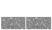 | ||
| Treated | This technology is neither commonly known nor frequently used; it can be treated as an experimental and innovative group | vertical joint (as above) followed by infrared gas burner used for heating of joint; Infrared (IR) heating can be applied before, during or after next hot-paved layer is placed | IR | 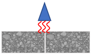 |
| vertical joint (as described in VJ subgroup) followed by microwave applicator used for heating of joint; Microwave (MW) heating can be applied before, during or after next hot-paved layer is placed | MW | 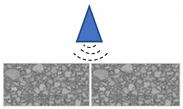 | ||
| Sealed | This technology is most commonly used; there are additional thermoplastic, bitumen-based materials applied to seal the vertically performed joint | vertical joint (as described in VJ subgroup) followed by application of thermoplastic bituminous sealing tapes before placing of next hot-paved layer | T1 T2 | 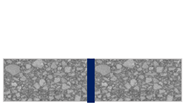 |
| vertical joint (as described in VJ subgroup) followed by application of bituminous sealing paste: organic solvent-based bitumen emulsion based before placing of next hot-paved layer | P1 P2 | 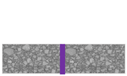 | ||
| Crack repair | Crack was repaired using microwave heating technique | microwave applicator is used to reheat the cracked pavement; additional operations can be added before (e.g. cleaning) or after (remixing, compaction) the microwave treatment | CR | 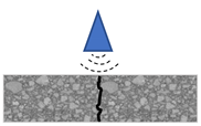 |
| Mix Designation | SMA 8 G | SMA 8 B | AC 16 W | AC 16 B |
|---|---|---|---|---|
| Aggregate Type | 100% Gabbro | 100% Basalt | 100% Limestone | 100% Basalt |
| Sieve Size, mm (Square Opening) | % Mass | % Mass | % Mass | % Mass |
| 22.4 | − | − | 100.0 | 100.0 |
| 16 | − | − | 97.9 | 98.4 |
| 11.2 | 100.0 | 100.0 | 77.3 | 76.3 |
| 8 | 96.6 | 96.8 | 60.8 | 59.4 |
| 5.6 | 59.7 | 55.0 | 46.9 | 46.2 |
| 2 | 29.5 | 27.7 | 24.9 | 27.7 |
| 0.5 | − | − | 13.3 | 13.3 |
| 0.125 | 12.3 | 12.5 | 7.5 | 8.1 |
| 0.063 | 11.0 | 10.0 | 6.5 | 6.6 |
| Binder | 7.3 | 6.7 | 4.3 | 4.6 |
| Binder type | PMB 45/80–55 | PMB 45/80–55 | 35/50 | 35/50 |
| Max density, Mg/m3 | 2.601 | 2.566 | 2.528 | 2.692 |
| Bulk density ssd, Mg/m3 | 2.530 | 2.479 | 2.414 | 2.525 |
| Voids content, % v/v | 2.7 | 3.4 | 4.4 | 6.2 |
| Dielectric constant ε′ | 5.76–6.04 | 6.45–6.74 | 6.51–7.01 | 6.60–7.22 |
| Stage of the Experiment | Location of Joint | Jointed Mixes Types |
|---|---|---|
| II | the joint between binder courses hot by cold | AC 16 W–AC 16 B AC 16 W–AC 16 W |
| III | the joint between wearing courses hot by cold | SMA 8 G–SMA 8 B SMA 8 B–SMA 8 B |
| IV | crack repair using microwaves | AC 11–AC 11 |
| Material Designation | T1 | T2 | P1 | P2 |
|---|---|---|---|---|
| Material Type | Bituminous Sealing Tape | Bituminous Sealing Tape (Self-Adhesive) | Bituminous Sealing Paste (Solvent-Based) | Bituminous Sealing Paste (Emulsion-Based) |
| Cone penetration, 0.1 mm | 49.6 | 43.0 | 32.3 | 40.0 |
| Softening point, °C | >150 | 113.9 | >150 | >150 |
| Flow resistance, mm | 0.0 | 0.0 | 0.0 | 0.0 |
| Elastic recovery, % | 11 | 20 | 14 | 10 |
| Frost resistance, balls uncracked | 4 | 4 | 4 | 4 |
| Continuous extension | ||||
| -max. elongation, % | ≥10 | ≥10 | ≥10 | 3 |
| -max. force, kN | 5.43 | 13.74 | 4.10 | 8.27 |
| Type of break at 10% | No break | No break | No break | Cohesion break |
| Cold bending (temp.) | No cracks | No cracks | – | – |
| −20 °C | −10 °C | |||
| Discontinuous extension at −10 °C | ||||
| -% | 33 | 33 | 33 | 33 |
| -max. tension stress, MPa | 0.2 | 0.6 | 1.5 | 1.0 |
| Test Method | Test Protocol | Specimen Size, Type | Test Conditions |
|---|---|---|---|
| Mechanical Tests | |||
| Indirect tensile strength ITS (split tension test) | PN-EN 12697-23, met. A | 100 mm cylindrical, cored from the pavement | 0 °C |
| Bending tensile strength SCB (semi-circular bending) | PN-EN 12697-44, no cut | 150 mm half-cylindrical, cored from the pavement and cut in half | 0 °C |
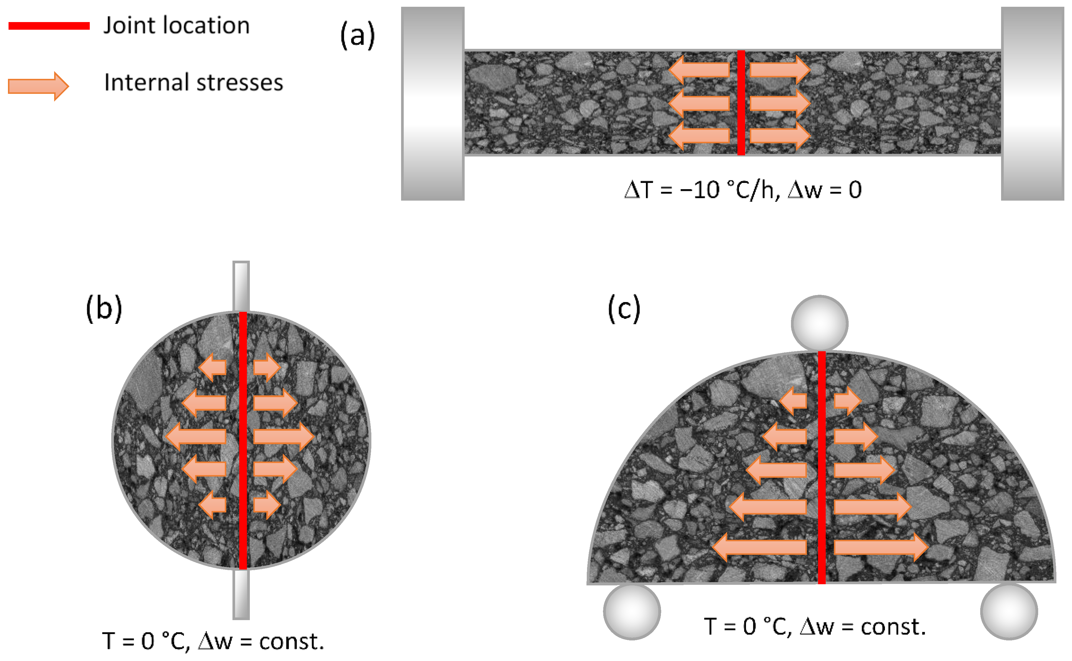
| Direct tension TSRST (thermal stress restrained specimen) | PN-EN 12697-46, TSRST | 40 mm × 40 mm × 200 mm beam, cut from 100 mm × 100 mm × 200 mm slab cut from pavement | (+10)–(−40) °C (Δ = −10 °C/h) |
| Physical Properties | |||
| Degree of compaction | PN-EN 13108-21, C.4 PN-EN 12697-6, met. B, 25 °C and D | 100 mm cylindrical cores | +25 °C |
| Aging Stages | Description | 35/50 | PMB 45/80–55 |
|---|---|---|---|
| No aging | 0A | + | + |
| No aging + microwaves | 0A + M:800–900 | + | + |
| RTFOT | 1R | + | + |
| RTFOT + PAV | 1P | + | + |
| RTFOT + microwaves | 1R + M:800–900 | + | + |
| RTFOT + PAV + microwaves | 1P + M:800–900 | + | + |
| Stage | Difference of Levels | Difference of Means, MPa | SE of Difference, MPa | 90% CI, MPa | T-Value | Adjusted p-Value | |
|---|---|---|---|---|---|---|---|
| II | MW–IR | −0.075 | 0.355 | (−1.130; | 0.980) | −0.21 | 1.000 |
| II | P1–MW | −1.273 | 0.425 | (−2.534; | −0.012) | −3.0 | 0.096 |
| II | P2–MW | −1.281 | 0.537 | (−2.876; | 0.314) | −2.39 | 0.240 |
| II | T2–MW | −0.52 | 0.380 | (−1.648; | 0.608) | −1.37 | 0.744 |
| II | VJ–MW | 0.238 | 0.355 | (−0.817; | 1.293) | 0.67 | 0.982 |
| III | MW–IR | −0.222 | 0.404 | (−1.374; | 0.931) | −0.55 | 0.998 |
| III | P1–MW | −2.712 | 0.467 | (−4.042; | −1.382) | −5.81 | 0.000 |
| III | SJ–MW | −0.083 | 0.387 | (−1.186; | 1.020) | −0.21 | 1.000 |
| III | T1–MW | −1.138 | 0.437 | (−2.382; | 0.107) | −2.61 | 0.163 |
| III | T2–MW | −0.91 | 0.404 | (−2.062; | 0.242) | −2.25 | 0.302 |
| Stage | Difference of Levels | Difference of Means, °C | SE of Difference, °C | 90% CI, °C | T-Value | Adjusted p-Value | |
|---|---|---|---|---|---|---|---|
| II | MW–IR | −0.86 | 4.11 | (−13.08; | 11.35) | −0.21 | 1.000 |
| II | P1–MW | 2.08 | 4.92 | (−12.52; | 16.69) | 0.42 | 0.998 |
| II | P2–MW | −3.34 | 6.22 | (−21.81; | 15.13) | −0.54 | 0.993 |
| II | T2–MW | −19.25 | 4.4 | (−32.31; | −6.19) | −4.38 | 0.011 |
| II | VJ–MW | 0.17 | 4.11 | (−12.04; | 12.39) | 0.04 | 1.000 |
| III | MW–IR | 0.2 | 6.59 | (−19.09; | 19.49) | 0.03 | 1.000 |
| III | P1–MW | −8.54 | 7.61 | (−30.81; | 13.73) | −1.12 | 0.947 |
| III | P2–MW | 29.83 | 7.61 | (7.56; | 52.10) | 3.92 | 0.009 |
| III | SJ–MW | 1.12 | 6.31 | (−17.35; | 19.58) | 0.18 | 1.000 |
| III | T1–MW | −14.04 | 7.12 | (−34.87; | 6.80) | −1.97 | 0.515 |
| Stage | Difference of Levels | Difference of Means, MPa | SE of Difference, MPa | 90% CI, MPa | T-Value | Adjusted p-Value | |
|---|---|---|---|---|---|---|---|
| II + III | MW–P1 | 2206 | 498 | (671; | 3742) | 4.43 | 0.008 |
| II + III | MW–T1 | 1905 | 575 | (132; | 3678) | 3.31 | 0.066 |
| II + III | MW–T2 | 1665 | 525 | (46; | 3283) | 3.17 | 0.085 |
| II + III | MW–P2 | 789 | 481 | (−694; | 2273) | 1.64 | 0.722 |
| II + III | VJ–MW | 55 | 525 | (−1564; | 1674) | 0.10 | 1.000 |
| II + III | IR–MW | 860 | 525 | (−758; | 2479) | 1.64 | 0.723 |
| II + III | SJ–MW | 1506 | 575 | (−267; | 3280) | 2.62 | 0.218 |
| Stage | Difference of Levels | Difference of Means, MPa | SE of Difference, MPa | 90% CI, MPa | T-Value | Adjusted p-Value | |
|---|---|---|---|---|---|---|---|
| II + III | MW–P1 | 423.3 | 62.1 | (231.7; | 614.8) | 6.81 | 0.000 |
| II + III | MW–T1 | 407.3 | 71.7 | (186.1; | 628.5) | 5.68 | 0.001 |
| II + III | MW–T2 | 398.2 | 65.5 | (196.3; | 600.1) | 6.08 | 0.000 |
| II + III | MW–P2 | 174.7 | 60.0 | (−10.4; | 359.7) | 2.91 | 0.135 |
| II + III | VJ–MW | −136.5 | 65.5 | (−338.5; | 65.4) | −2.08 | 0.462 |
| II + III | IR–MW | 78.3 | 65.5 | (−123.7; | 280.2) | 1.19 | 0.922 |
| II + III | SJ–MW | 41.9 | 71.7 | (−179.3; | 263.1) | 0.58 | 0.999 |
| Stage | Difference of Levels | Difference of Means, MPa | SE of Difference, MPa | 90% CI, MPa | T-Value | Adjusted p-Value | |
|---|---|---|---|---|---|---|---|
| II + III | MW–P1 | 7.6 | 0.6 | (6.006; | 9.266) | 13.3 | 0.000 |
| II + III | MW–T1 | 6.5 | 0.5 | (5.025; | 7.940) | 12.6 | 0.000 |
| II + III | MW–T2 | 6.2 | 0.4 | (4.900; | 7.406) | 13.9 | 0.000 |
| II + III | MW–P2 | 5.8 | 0.5 | (4.425; | 7.091) | 12.3 | 0.000 |
| II + III | MW–VJ | 2.0 | 0.5 | (0.654; | 3.328) | 4.2 | 0.002 |
| II + III | MW–IR | 0.8 | 0.5 | (0.543; | 2.056) | 1.7 | 0.718 |
| II + III | MW–SJ | −1.9 | 0.7 | (−3.890; | 0.033) | −2.8 | 0.113 |
| Stage | Difference of Levels | Difference of Means | SE of Difference | 90% CI | T-Value | Adjusted p-Value | |
|---|---|---|---|---|---|---|---|
| III | SJ–MW | −0.0423 | 0.0249 | (−0.0838; | −0.0007) | −1.70 | 0.095 |
| III | IR–MW | −0.0431 | 0.0249 | (−0.0847; | −0.0015) | −1.73 | 0.088 |
| III | P2–MW | −0.0884 | 0.0228 | (−0.1264; | −0.0504) | −3.89 | 0.000 |
| III | P1–MW | −0.1041 | 0.0249 | (−0.1457; | −0.0625) | −4.18 | 0.000 |
| III | VJ–MW | −0.1037 | 0.0236 | (−0.1431; | −0.0642) | −4.38 | 0.000 |
| III | T2–MW | −0.1525 | 0.0249 | (−0.1941; | −0.1109) | −6.12 | 0.000 |
| III | T1–MW | −0.1694 | 0.0236 | (−0.2088; | −0.1299) | −7.16 | 0.000 |
Publisher’s Note: MDPI stays neutral with regard to jurisdictional claims in published maps and institutional affiliations. |
© 2021 by the authors. Licensee MDPI, Basel, Switzerland. This article is an open access article distributed under the terms and conditions of the Creative Commons Attribution (CC BY) license (https://creativecommons.org/licenses/by/4.0/).
Share and Cite
Maliszewski, M.; Zofka, A.; Maliszewska, D.; Sybilski, D.; Salski, B.; Karpisz, T.; Rembelski, R. Full-Scale Use of Microwave Heating in Construction of Longitudinal Joints and Crack Healing in Asphalt Pavements. Materials 2021, 14, 5159. https://doi.org/10.3390/ma14185159
Maliszewski M, Zofka A, Maliszewska D, Sybilski D, Salski B, Karpisz T, Rembelski R. Full-Scale Use of Microwave Heating in Construction of Longitudinal Joints and Crack Healing in Asphalt Pavements. Materials. 2021; 14(18):5159. https://doi.org/10.3390/ma14185159
Chicago/Turabian StyleMaliszewski, Maciej, Adam Zofka, Dominika Maliszewska, Dariusz Sybilski, Bartłomiej Salski, Tomasz Karpisz, and Rafał Rembelski. 2021. "Full-Scale Use of Microwave Heating in Construction of Longitudinal Joints and Crack Healing in Asphalt Pavements" Materials 14, no. 18: 5159. https://doi.org/10.3390/ma14185159
APA StyleMaliszewski, M., Zofka, A., Maliszewska, D., Sybilski, D., Salski, B., Karpisz, T., & Rembelski, R. (2021). Full-Scale Use of Microwave Heating in Construction of Longitudinal Joints and Crack Healing in Asphalt Pavements. Materials, 14(18), 5159. https://doi.org/10.3390/ma14185159