Article

Parameter Interval Uncertainty Analysis of Internal Resonance of Rotating Porous Shaft–Disk–Blade Assemblies Reinforced by Graphene Nanoplatelets

1
School of Control Engineering, Northeastern University at Qinhuangdao, Qinhuangdao 066004, China
2
AVIC Xi’an Aircraft Industry Group Company Ltd., Xi’an 710089, China
3
School of Science, Northeastern University, Shenyang 110819, China
4
School of Engineering, RMIT University, P.O. Box 71, Bundoora, Melbourne, VIC 3083, Australia
*
Authors to whom correspondence should be addressed.
Materials 2021, 14(17), 5033; https://doi.org/10.3390/ma14175033
Submission received: 31 March 2021 / Revised: 19 August 2021 / Accepted: 1 September 2021 / Published: 3 September 2021

Abstract

:
This paper conducts a parameter interval uncertainty analysis of the internal resonance of a rotating porous shaft–disk–blade assembly reinforced by graphene nanoplatelets (GPLs). The nanocomposite rotating assembly is considered to be composed of a porous metal matrix and graphene nanoplatelet (GPL) reinforcement material. Effective material properties are obtained by using the rule of mixture and the Halpin–Tsai micromechanical model. The modeling and internal resonance analysis of a rotating shaft–disk–blade assembly are carried out based on the finite element method. Moreover, based on the Chebyshev polynomial approximation method, the parameter interval uncertainty analysis of the rotating assembly is conducted. The effects of the uncertainties of the GPL length-to-width ratio, porosity coefficient and GPL length-to-thickness ratio are investigated in detail. The present analysis procedure can give an interval estimation of the vibration behavior of porous shaft–disk–blade rotors reinforced with graphene nanoplatelets (GPLs).

1. Introduction

Shaft–disk–blade assemblies are commonly applied in many rotor structures, such as gas turbines, aero-engines, and so on. It is reported that more than 60% of faults of shaft–disk–blade assemblies are due to vibration faults. Thus, many scholars have focused on the vibration behaviors of shaft–disk–blade assemblies [1,2,3]. However, modern rotating machinery is faced with high temperatures and high pressures under multiple physical fields. Traditional materials cannot meet the requirements of high strength and light weight at the same time. It is quite necessary to introduce an advanced composite to solve this issue.
Graphene [4,5] is the most popular advanced material in the world because of its outstanding mechanical performance since being discovered. In recent years, GPLs, which have great reinforcing effect at low contents [6], have attracted a lot of attention [7,8,9,10]. Jie Yang, Sritawat Kitipornchai and their partners have contributed many achievements about the vibration characteristics of structures reinforced by GPLs [11,12,13,14,15]. Twinkle et al. [16] studied the vibrations of porous cylindrical panels reinforced with GPLs. Considering the effect of the elastic medium, Mohammad et al. [17] investigated the nonlinear performance of a GPL-reinforced functionally graded (FG) conical panel. Within the frame of the shear deformable theory, Salehi et al. [18] developed an analytical method to obtain the nonlinear vibration behavior of an imperfect porous cylindrical shell reinforced by GPLs. Considering conveying fluid flow, dynamic behaviors of porous sandwich pipes reinforced by GPLs are presented by Nejadi et al. [19]. The analysis of the vibrations of an FG spherical shell reinforced by GPLs was carried out by Liu et al. [20]. Zhao et al. [21,22,23,24,25] conducted a dynamic analysis of FG-GPL-reinforced nanocomposite disk–shaft, blade–disk and blade–shaft rotor systems. By adopting the spectral Chebyshev approach, Mirmeysam et al. [26] studied the inherent characteristics of an FG plate reinforced by GPLs. To the best of the authors’ knowledge, few studies have focused on GPL-reinforced shaft–disk–blade assemblies. Thus, it is important to study the vibration behavior of GPL-reinforced shaft–disk–blade assemblies. In addition, the matrix should be porous metal [27,28,29,30,31,32] to achieve a light weight.
As GPLs are nanofillers, the dimensions of a single GPL are difficult to obtain. Thus, statistical values for the dimensions are adopted. Moreover, the porosity is an approximate measurement for the dimension and density of the pores. The uncertain issue has to exist in the vibration analysis of the porous shaft–disk–blade reinforced by GPLs. If those uncertainties are ignored, the mechanical performance of the porous shaft–disk–blade rotor is partial and cannot be used in practical engineering.
However, the uncertainty analysis of porous structures reinforced with GPLs is extremely limited. Only Baghlani et al. [33] examined the influences of property uncertainties on the free vibration behavior of an FG-GPL-reinforced porous shell. This paper aims to conduct an uncertainty analysis of the internal resonance of porous shaft–disk–blade assemblies reinforced by GPLs. The modeling and internal resonance analysis of the shaft–disk–blade assembly are presented based on the finite element method. In addition, on the basis of the Chebyshev polynomial approximation method, the parameter interval uncertainty analysis of the assembly is conducted. A parametric study is given to investigate the impact of the uncertain porosity coefficient, uncertain GPL length-to-width ratio and uncertain GPL length-to-thickness ratio.

2. Physical Model

A spinning shaft–disk–blade model is given in Figure 1. The connections between the shaft, disk and blades are taken to be ideal, where the supports are considered simply supported. The shaft–disk–blade structure is composed of graphene nanoplatelets and porous copper metal foam.
Based on the open-cell scheme [34], the Poisson’s ratio, mass density and Young’s modulus are:
{ υ ( z ) = υ * ( z ) ρ ( z ) = ρ * ( z ) e n E ( z ) = E * ( z ) e 1
in which en and e1 are the mass density coefficients and porosity coefficients, respectively; and υ*(z), ρ*(z) and E*(z) are the Poisson’s ratio, mass density and Young’s modulus in the case of no pores, respectively.
According to the mechanical properties of porous metal foam [35], one can obtain:
E ( z ) E * ( z ) = [ ρ ( z ) ρ * ( z ) ] 2
Thus, one can obtain:
e n = e 1
On the basis of the Halpin–Tsai theory [36], Young’s modulus in the case of no pores is:
E * ( z ) = 5 8 ( 1 + ξ w η w V GPL 1 η w V GPL ) E M + 3 8 ( 1 + ξ l η l V GPL 1 η l V GPL ) E M
where ξl and ξw are the dimension factors of GPLs, and ξl and ξw are:
{ η w = 1 E M / E GPL 1 + E M ξ w / E GPL η l = 1 E M / E GPL 1 + E M ξ l / E GPL
in which EM and EGPL are the Young’s modulus of the matrix and GPLs, respectively.
Herein, ξw and ξl are given by:
{ ξ w = 2 w GPL / h GPL ξ l = 2 l GPL / h GPL
where hGPL, wGPL and lGPL are the GPL thickness, GPL width and GPL length, respectively.
According to the rule of mixture, υ*(z) and ρ*(z) are given by:
{ υ * ( z ) = ( υ GPL υ M ) V GPL + υ M ρ * ( z ) = ( ρ GPL ρ M ) V GPL + ρ M
in which υM and ρM are the Poisson’s ratio and mass density of the matrix, respectively; υGPL and ρGPL are the Poisson’s ratio and mass density of GPLs, respectively; and the GPL volume fraction is:
V GPL ( z ) = W GPL ( z ) ρ M W GPL ( z ) ρ M + [ 1 W GPL ( z ) ] ρ GPL
The GPL weight fraction (WGPL) is expressed as:
W GPL ( z ) = λ W 0
where W0 and λ are the characteristic value and weight fraction index of GPLs, respectively.

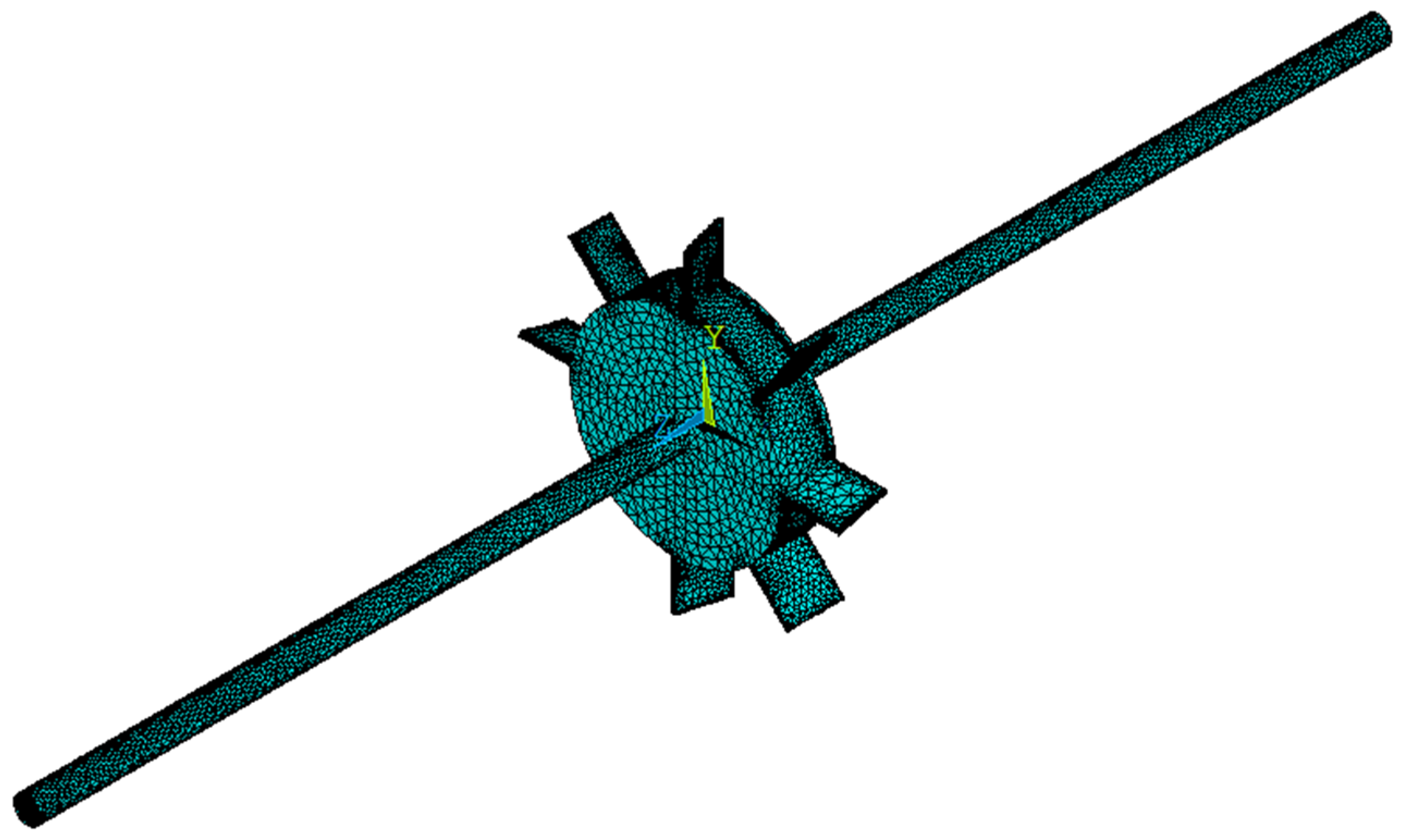
3. Finite Element Implementation

Solid elements with eight nodes are adopted in this paper and their displacements are given by:
{ u v w } T = j = 1 8 N j { u j v j w j } T
in which (ui, vi, wi) and Ni are the node displacements and shape functions, respectively.
The expressions of shape functions are:
{ N 1 = 0.125 ( 1 z * ) ( 1 y * ) ( 1 x * ) N 2 = 0.125 ( 1 z * ) ( 1 + y * ) ( 1 x * ) N 3 = 0.125 ( 1 + z * ) ( 1 + y * ) ( 1 x * ) N 4 = 0.125 ( 1 + z * ) ( 1 y * ) ( 1 x * ) N 5 = 0.125 ( 1 z * ) ( 1 y * ) ( 1 + x * ) N 6 = 0.125 ( 1 z * ) ( 1 + y * ) ( 1 + x * ) N 7 = 0.125 ( 1 + z * ) ( 1 + y * ) ( 1 + x * ) N 8 = 0.125 ( 1 + z * ) ( 1 y * ) ( 1 + x * )
where z*, y* and x* are the element coordinates.
The physical equation is:
δ = { δ x δ y δ z τ x y τ y z τ z x } T = D { ε x ε y ε z γ x y γ y z γ z x } T = D ε
where (γxy, γyz, γzx) are the shear strains; (εx, εy, εz) are the normal strains; (τxy, τyz, τzx) are the shear stresses; (δx, δy, δz) are the normal stresses; and the elastic material matrix D is:
D = E 1 + υ [ 1 υ 1 2 υ υ 1 2 υ υ 1 2 υ 0 0 0 υ 1 2 υ 1 υ 1 2 υ υ 1 2 υ 0 0 0 υ 1 2 υ υ 1 2 υ 1 υ 1 2 υ 0 0 0 0 0 0 1 2 0 0 0 0 0 0 1 2 0 0 0 0 0 0 1 2 ]
Then, one can obtain that:
ε = { u x u y w z u y + v x v z + u y u z + w x } = [ x 0 0 y 0 z 0 y 0 x z 0 0 0 z 0 y x ] T { u v w }
Setting
ϕ = { u   v   w   } T = { φ u   φ v   φ w   } T
and supplying Equation (15) into Equation (14) gives:
ε = B ϕ
where B is the geometric matrix; and φw, φv and φu are the node displacement vectors along the z-axis, y-axis and x-axis, respectively.
B can be written as:
B = [ x 0 0 y 0 z 0 y 0 x z 0 0 0 z 0 y x ] T [ N N N ]
in which N = {N1, N2, …, N8}.
The deformation energy and kinetic energy are:
{ U = V 1 2 δ T ε d V = V 1 2 ϕ T B T D B ϕ d V T = ρ V 1 2 δ T N T N δ d V
Considering the expressions:
{ U ϕ = K ϕ T ϕ = M ϕ
give the stiffness matrix K and mass matrix M, indicated as:
{ K = V B T D B d V M = ρ V N T N d V
The equations of motion are:
M ü + K u = F
where F is the harmonic exciting force vector; and u is the harmonic response vector. Their expressions are:
{ F = F max e i ω t u = u max e i ω t
Substituting Equation (22) into Equation (21) gives:
( ω 2 M + K ) u max = F max
Thus, the relation between the response and frequency can be obtained from Equation (23).

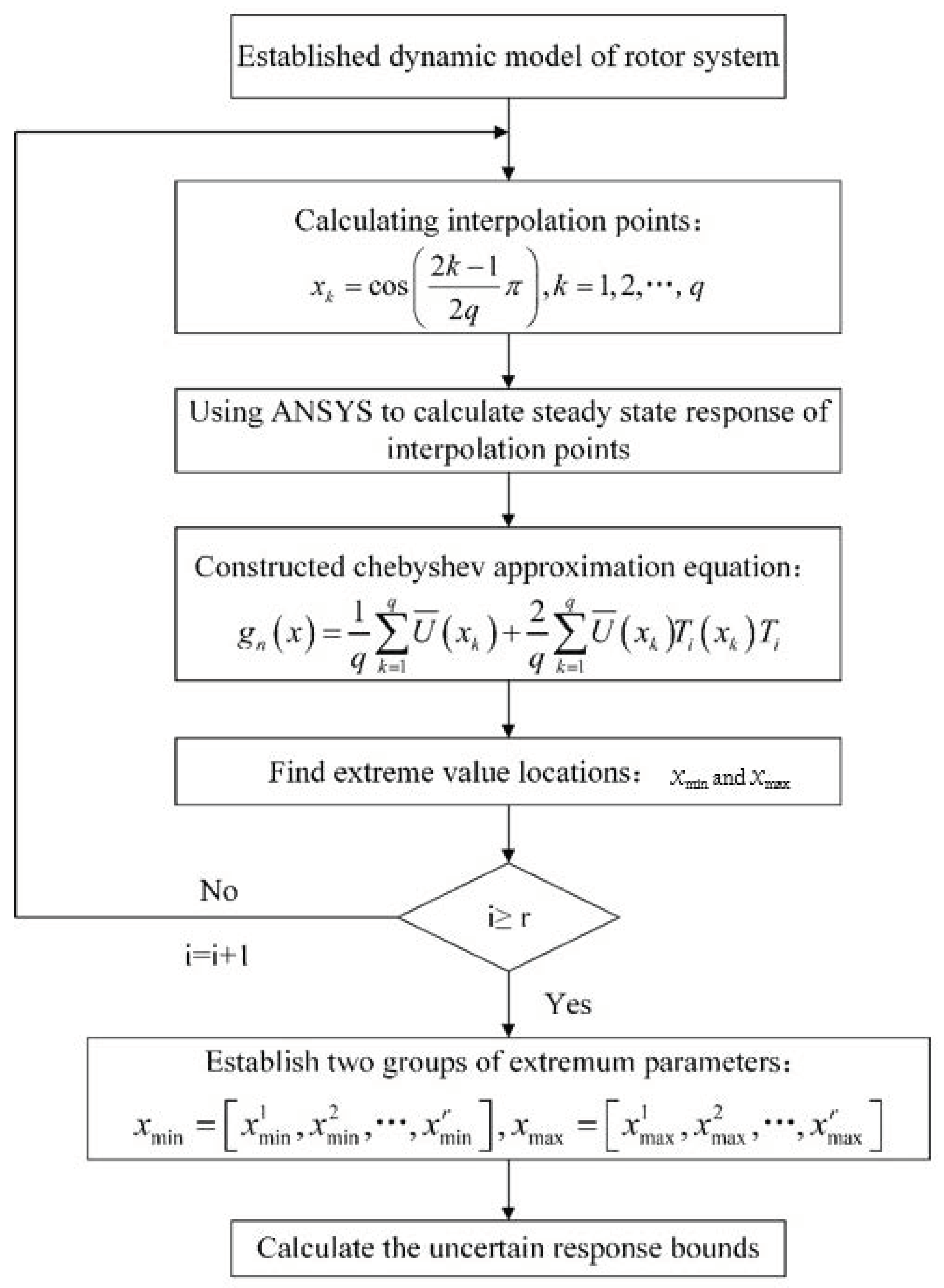
4. Interval Uncertainty Analysis

The first kind of Chebyshev orthogonal polynomial is:
T n ( x ) = cos [ n arccos ( x ) ] ,   x [ 1 , 1 ]
As the first kind of Chebyshev orthogonal polynomial is orthogonal to:
ρ ( x ) = 1 x 2
Equation (24) can be obtained as:
{ T 0 ( x ) = 1 T 1 ( x ) = x T n + 1 ( x ) = 2 x T n ( x ) T n 1 ( x ) ,   n = 1 , 2 ,
Based on the Weierstrass theorem, we can always find a polynomial function g(x) that satisfies:
g ( x ) f ( x ) ε
where ε is a small positive real number; and f(x) is a real function, which is defined in the real interval [−1, 1].
In the subspace Tn = span {T0, T1, …, Tn}, f(x) is established as:
f ( x ) g n ( x ) = A 0 2 + i = 0 n A i T i ( x ) ,   x [ 1 , 1 ]
in which Ai are undetermined coefficients in the form of:
A 0 = 2 π 1 1 f ( x ) 1 x 2 d x k = 1 q A k f ¯ ( x k ) A i = 2 π 1 1 f ( x ) T i ( x ) 1 x 2 d x k = 1 q A k f ¯ ( x k ) T i ( x k )
where k = 1, 2, …, q; q is the number of interpolation points; and Ak is the Gaussian integral coefficient. It is worth noting that the number of interpolation points must be greater than the order of the approximation equation.
For Chebyshev Gaussian integrals, the interpolation points can be given by:
x k = cos ( 2 k 1 2 q π ) ,   k = 1 , 2 , , q
The Gaussian integral coefficients can be calculated by:
A ¯ k = 1 1 T q ( x ) 1 x 2 ( x x k ) T q ( x k ) d x = π q
Substituting Equations (29)–(31) into Equation (28) gives:
g n ( x ) = 1 q k = 1 q f ¯ ( x k ) + 2 q i = 1 n k = 1 q f ¯ ( x k ) T i ( x k ) T i ( x )
Thus, the orthogonal approximation is obtained as Equation (32).
In this paper, interval uncertainty analysis is conducted for the porous shaft–disk–blade assembly reinforced by GPLs. The uncertainty parameters are taken into account as the porosity coefficient, GPL length-to-thickness ratio and GPL length-to-width ratio. For convenience, the considered uncertainty parameters are defined as aI. Its expression is:
a I = [ a _ , a ¯ ] = { a R | a _ a a ¯ }
where a _ and a ¯ are lower boundaries and upper boundaries of the uncertainty parameter and R is the real number collection.
Setting
a c = a _ + a ¯ 2 ,   β = a _ a ¯ 2
and supplying Equation (34) into Equation (33) give:
a I = [ a _ , a ¯ ] = [ a c β a c , a c + β a c ]
in which β is the fluctuation coefficient and ac is the median value of the uncertainty parameter.
If the number of uncertainty parameters of the shaft–disk–blade assembly is m, it can be expressed as:
a I = [ a 1 I , a 2 I , , a m I ] a i I = [ a i I _ , a i I ¯ ] ,   i = 1 , 2 , m
As the Chebyshev orthogonal approximation is defined in the standard interval [−1, 1], the linear transformation is needed as:
x i = 2 a i ( a _ i + a ¯ i ) a ¯ i a _ i ,   x i [ 1 , 1 ] ,   a i [ a _ i , a ¯ i ]
For each single uncertainty parameter, the interval steady-state response of the assembly can be expressed as:
g n ( x ) = 1 q k = 1 q U ¯ ( x k ) + 2 q i = 1 n k = 1 q U ¯ ( x k ) T i ( x k ) T i ( x )
where U ¯ ( x k ) is the deterministic response at point xk.
The extremum point is:
{ x roots | g n ( x roots ) = 0 }
Thus, the steady-state response boundary of the assembly in the presence of the uncertain parameter can be obtained by comparing among gn(−1), gn(xroots) and gn(1).
Xmin and Xmax are written as the values of independent variables when gn(x) obtains the smallest and largest values, respectively. In the case of r interval variables, uncertainty analysis should be conducted for each one. The two marked corresponding independent variables are:
x min = [ x min 1 , x min 2 , , x min r ] x max = [ x max 1 , x max 2 , , x max r ]
Therefore, the actual parameter vectors of the steady-state response boundaries are:
a min = a c + ( a ¯ a _ ) × x min a max = a c + ( a ¯ a _ ) × x max
The detailed flow is shown in Figure 2.

5. Results and Discussions

Before uncertainty analysis with different parameters is conducted, the experimental validation part is presented first. Due to the manufacturing difficulties of a GPL-reinforced porous structure, a metal alloy shaft–disk–blade assembly is proposed for the validation experiment. From reference [37], it can be noted that the model in this paper has sufficient accuracy.
The uncertainty analysis of the porous shaft–disk–blade assembly reinforced by GPLs is conducted in this part. The blade setting angle, blade thickness, blade width and blade length are 15°, 1.5 mm, 18 mm and 20 mm, respectively; the disk thickness and disk diameter are 20 mm and 78 mm, respectively; the shaft diameter and shaft length are 10 mm and 500 mm, respectively; and the material parameters are ρM = 8960 kg/m3, υM = 0.34, EM = 130 Gpa, ρGPL = 1062.5 kg/m3, υGPL = 0.186, EGPL = 1050 Gpa, e1 = 0.1, lGPL/wGPL = 2, lGPL/hGPL = 10 and gGPL= 1%.
Figure 3, Figure 4 and Figure 5 plot the amplitude–frequency response (AFR) of the shaft–disk–blade assembly with a single uncertain porosity coefficient, uncertain GPL length-to-width ratio and uncertain GPL length-to-thickness ratio, respectively. It can be found that the upper boundary of vibration amplitude goes up and the lower boundary of vibration amplitude moves down with the increase in the fluctuation coefficient of the uncertain parameters, which tells us that a larger fluctuation coefficient leads to more uncertain results. Meanwhile, the upper boundary and lower boundary are symmetric about the deterministic response. The formants with different fluctuation coefficients do not shift because the structural damping and external excitation have little effect on the natural frequency of the assembly. Moreover, the uncertain parameters (porosity coefficient, GPL length-to-width ratio and GPL length-to-thickness ratio) make the fluctuation of the resonance peak (around 428 Hz) larger and the fluctuation of the non-resonance peak (away from 428 Hz) smaller. This tells us that structural damping has a great effect on the resonance peak, but little effect on the non-resonance peak.
By comparison with Figure 4, Figure 5 and Figure 6, one can see that the fluctuation coefficient of the GPL length-to-thickness ratio has the greatest influence on the amplitude–frequency response, while that of porosity has the lowest impact. This implies that the thickness and surface area of GPLs are important indexes in the manufacturing of shaft–disk–blade assemblies.
Figure 6, Figure 7 and Figure 8 display the AFR of the shaft–disk–blade assembly with double uncertain parameters (porosity coefficient, GPL length-to-thickness ratio and GPL length-to-width ratio). One can see that the fluctuation of the amplitude–frequency response with double uncertain parameters is much stronger than that with a single uncertain parameter. In the case of double uncertain parameters, the width of the resonance peak region is increased significantly. However, the non-resonance peak region is affected very little by the double uncertain parameters. In addition, it is found that the AFR with an uncertain GPL length-to-thickness ratio and GPL length-to-width ratio has the largest fluctuation effect compared to the other two cases. This implies that the dimensions of GPLs have greater effects on the mechanical performance of the rotor system as thinner GPLs with larger surface areas provide better load transfer capability.

6. Conclusions

In this paper, a GPL-reinforced porous shaft–disk–blade assembly is established by employing the finite element method. According to the Chebyshev polynomial approximation method, the parameter interval uncertainty analysis of the internal resonance of the shaft–disk–blade assembly is carried out. Some conclusions are drawn as follows:
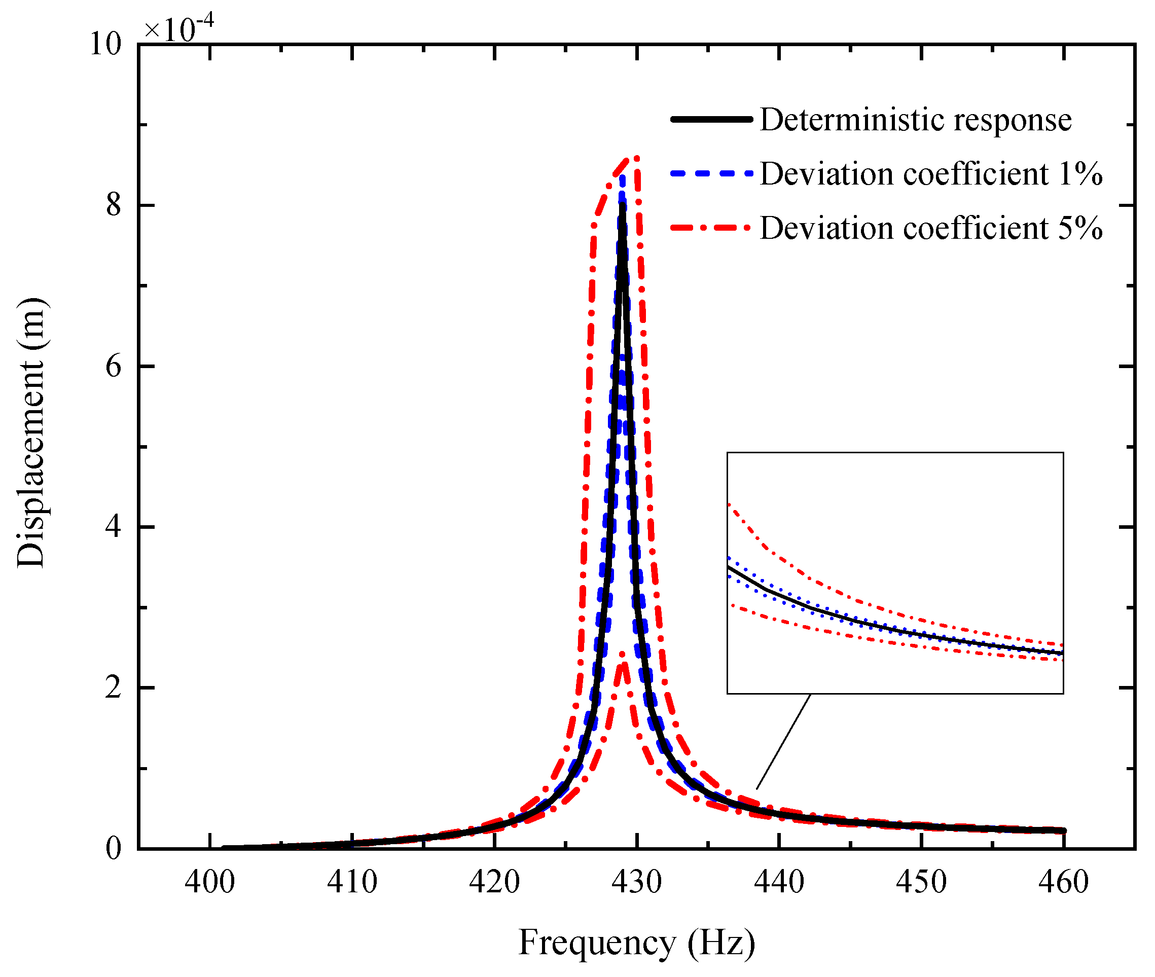
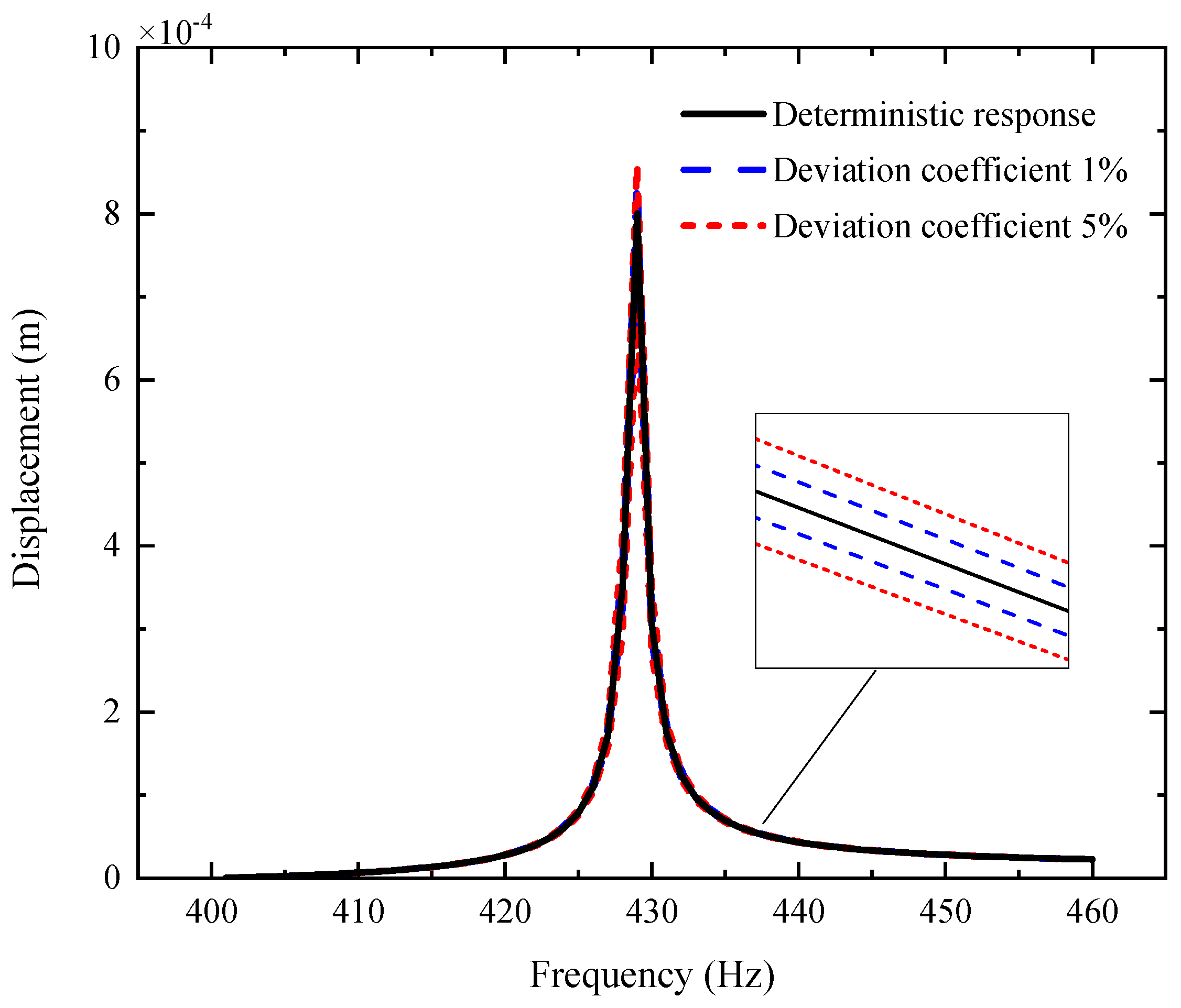
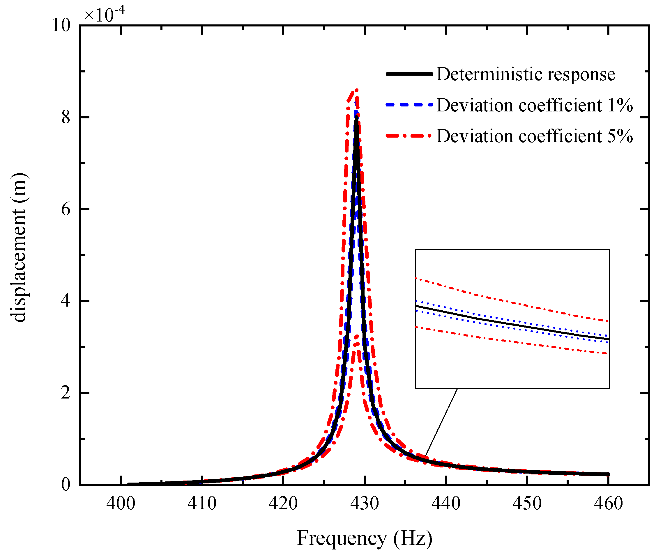
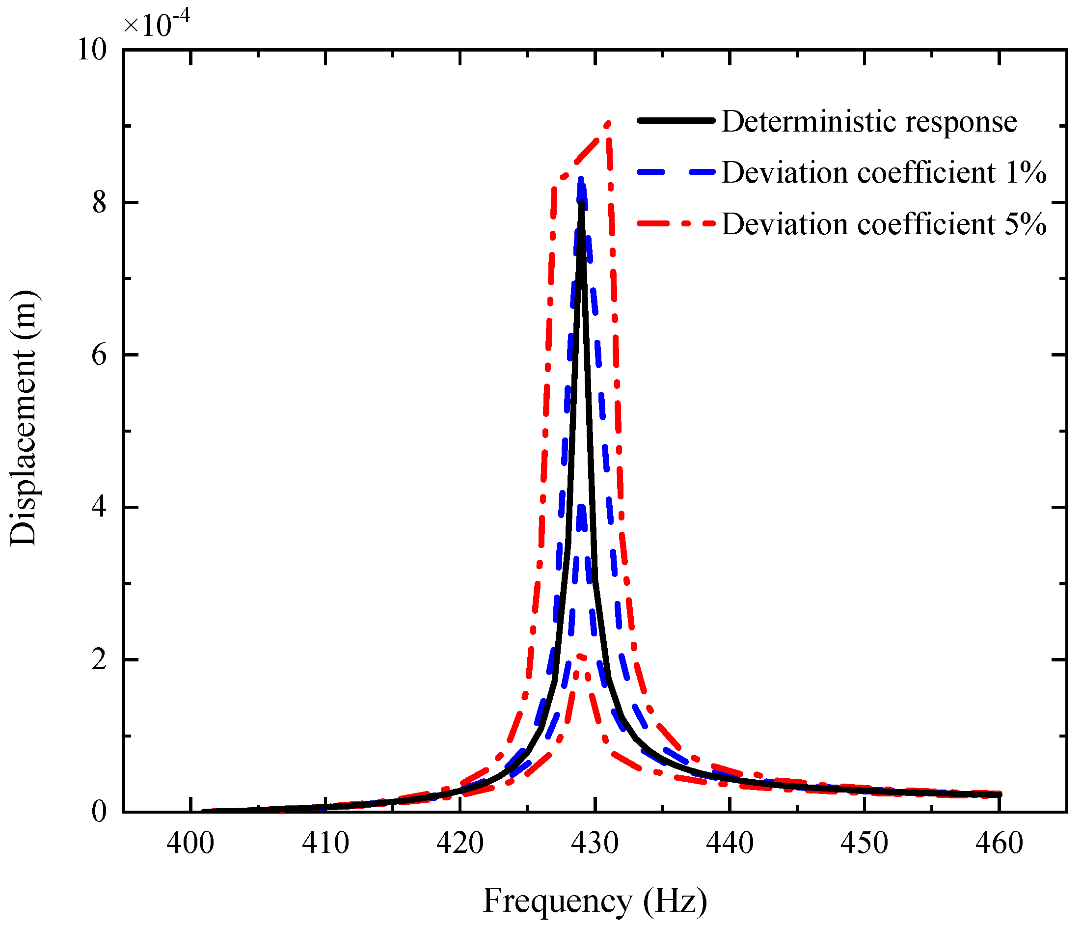
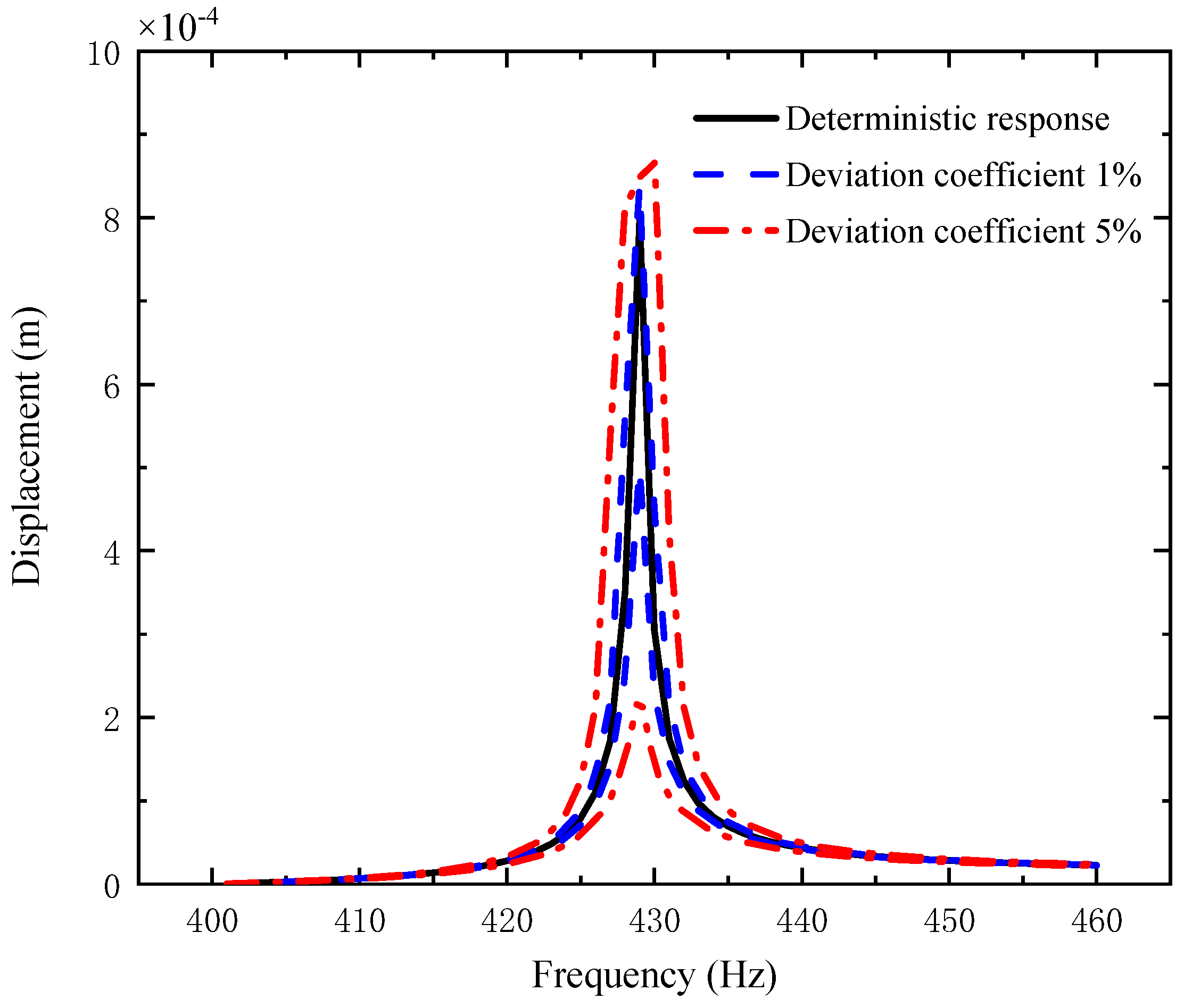
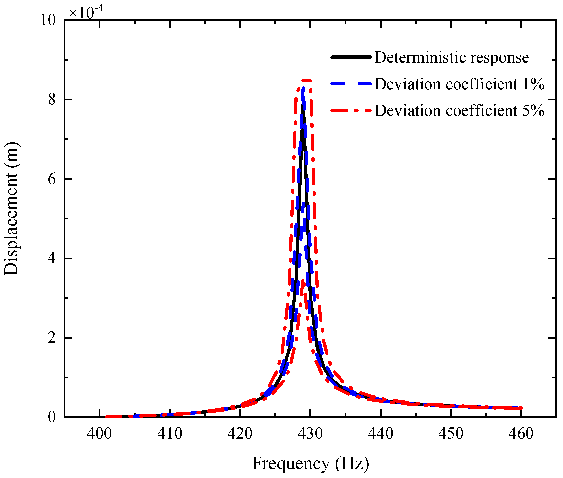
  • The uncertain parameters make the fluctuation of the resonance peak larger and the fluctuation of the non-resonance peak smaller.
  • The fluctuation coefficient of the GPL length-to-thickness ratio has the greatest influence on the amplitude–frequency response, while that of porosity has the lowest impact.
  • The fluctuation of the amplitude–frequency response with double uncertain parameters is much stronger than that with a single uncertain parameter.
  • The dimensions of GPLs have greater effects on the vibration behavior of the shaft–disk–blade assembly as thinner GPLs with larger surface areas provide better load transfer capability.

Author Contributions

Conceptualization, Y.C. and J.Y.; methodology, Y.C. and Z.-F.L.; software, Z.-F.L.; validation, T.-Y.Z.; formal analysis, T.-Y.Z.; investigation, Y.C. and Z.-F.L.; resources, T.-Y.Z.; data curation, Z.-F.L.; writing—original draft preparation, Y.C. and T.-Y.Z.; writing—review and editing, J.Y.; visualization, Z.-F.L.; supervision, J.Y.; project administration, T.-Y.Z.; funding acquisition, T.-Y.Z. All authors have read and agreed to the published version of the manuscript.

Funding

This research was funded by the key R&D plan of China for the Winter Olympics (No. 2021YFF0306403), the National Natural Science Foundation of China (No. 51805076, No. U1708255 and No. 51775093), the National Science and Technology Major Project of China (J2019-I-0008-0008), and the Fundamental Research Funds for the Central Universities of China (N2105013).

Conflicts of Interest

The authors declare no conflict of interest.

References

  1. She, H.X.; Li, C.F.; Tang, Q.S.; Wen, B.C. Influence mechanism of disk position and flexibility on natural frequencies and critical speeds of a shaft-disk-blade unit. J. Sound Vib. 2020, 469, 115156. [Google Scholar] [CrossRef]
  2. Heydari, H.; Khorram, A.; Afzalipour, L. The Influences of Stagger and Pretwist Angles of Blades on Coupling Vibration in Shaft-Disk-Blade Systems. J. Vib. Acoust. 2020, 142, 011007. [Google Scholar] [CrossRef]
  3. Li, C.F.; She, H.X.; Tang, Q.S.; Wen, B.C. The coupling vibration characteristics of a flexible shaft-disk-blades system with mistuned features. Appl. Math. Model. 2019, 67, 557–572. [Google Scholar] [CrossRef]
  4. Yadav, H.M.; Nath, N.C.D.; Kim, J.; Shinde, S.K.; Ramesh, S.; Hossain, F.; Ibukun, O.; Lee, J. Nickel-Graphene nanoplatelet deposited on carbon fiber as binder-free electrode for electrochemical supercapacitor application. Polymers 2020, 12, 1666. [Google Scholar] [CrossRef]
  5. Ding, B.; Fan, Z.; Lin, Q.; Wang, J.; Chang, Z.; Li, T.; Henzie, J.; Kim, J.; Dou, H.; Zhang, X.; et al. Confined Pyrolysis of ZIF-8 Polyhedrons Wrapped with Graphene Oxide Nanosheets to Prepare 3D Porous Carbon Heterostructures. Small Methods 2019, 3, 1900277. [Google Scholar] [CrossRef]
  6. Rafiee, M.A.; Rafiee, J.; Wang, Z.; Song, H.H.; Yu, Z.Z.; Koratkar, N. Enhanced mechanical properties of nanocomposites at low graphene content. ACS Nano 2009, 3, 3884–3890. [Google Scholar] [CrossRef] [PubMed]
  7. Yang, F.L.; Wang, Y.Q. Free and forced vibration of beams reinforced by 3D graphene foam. Int. J. Appl. Mech. 2020, 12, 2050056. [Google Scholar] [CrossRef]
  8. Wang, Y.Q.; Ye, C.; Zu, J.W. Nonlinear vibration of metal foam cylindrical shells reinforced with graphene platelets. Aerosp. Sci. Technol. 2019, 85, 359–370. [Google Scholar] [CrossRef]
  9. Zhao, T.Y.; Jiang, Z.Y.; Zhao, Z.; Xie, L.Y.; Yuan, H.Q. Modeling and free vibration analysis of rotating hub-blade assemblies reinforced with graphene nanoplatelets. J. Strain Anal. Eng. Des. 2021. [Google Scholar] [CrossRef]
  10. Zhao, T.Y.; Yang, Y.F.; Pan, H.G. Free vibration analysis of a spinning porous nanocomposite blade reinforced with graphene nanoplatelets. J. Strain Anal. Eng. Des. 2021. [Google Scholar] [CrossRef]
  11. Song, M.T.; Kitipornchai, S.; Yang, J. Free and forced vibrations of functionally graded polymer composite plates reinforced with graphene nanoplatelets. Compos. Struct. 2017, 159, 579–588. [Google Scholar] [CrossRef]
  12. Kitipornchai, S.; Chen, D.; Yang, J. Free vibration and elastic buckling of functionally graded porous beams reinforced by graphene platelets. Mater. Des. 2017, 116, 656–665. [Google Scholar] [CrossRef]
  13. Yang, J.; Wu, H.L.; Kitipornchai, S. Buckling and postbuckling of functionally graded multilayer graphene platelet-reinforced composite beams. Compos. Struct. 2017, 161, 111–118. [Google Scholar] [CrossRef] [Green Version]
  14. Chen, D.; Yang, J.; Kitipornchai, S. Nonlinear vibration and postbuckling of functionally graded graphene reinforced porous nanocomposite beams. Compos. Sci. Technol. 2017, 142, 235–245. [Google Scholar] [CrossRef] [Green Version]
  15. Feng, C.; Kitipornchai, S.; Yang, J. Nonlinear free vibration of functionally graded polymer composite beams reinforced with graphene nanoplatelets (GPLs). Eng. Struct. 2017, 140, 110–119. [Google Scholar] [CrossRef]
  16. Twinkle, C.M.; Jeyaraj, P. Free vibration and stability of graphene platelet reinforced porous nano-composite cylindrical panel: Influence of grading, porosity and non-uniform edge loads. Eng. Struct. 2021, 230, 111670. [Google Scholar]
  17. Mohammad, Y.A.J.; Pedram, B.; Mohammad, H.; Rasool, P. Nonlinear vibration analysis of functionally graded GPL-RC conical panels resting on elastic medium. Thin-Walled Struct. 2021, 160, 107370. [Google Scholar]
  18. Salehi, M.; Gholami, R.; Ansari, R. Analytical solution approach for nonlinear vibration of shear deformable imperfect FG-GPLR porous nanocomposite cylindrical shells. Mech. Based Des. Struct. Mach. 2021, 49, 430–439. [Google Scholar]
  19. Nejadi, M.M.; Mohammadimeehr, M.; Mehrabi, M. Free vibration and stability analysis of sandwich pipe by considering porosity and graphene platelet effects on conveying fluid flow. Alexandria Eng. J. 2021, 60, 1945–1954. [Google Scholar] [CrossRef]
  20. Liu, D.; Zhou, Y.; Zhu, J. On the free vibration and bending analysis of functionally graded nanocomposite spherical shells reinforced with graphene nanoplatelets: Three-Dimensional elasticity solutions. Eng. Struct. 2021, 226, 111376. [Google Scholar] [CrossRef]
  21. Zhao, T.Y.; Ma, Y.; Zhang, H.Y.; Yang, J. Coupled free vibration of spinning functionally graded porous double-bladed disk systems reinforced with graphene nanoplatelets. Materials 2020, 13, 5610. [Google Scholar] [CrossRef]
  22. Zhao, T.Y.; Jiang, L.P.; Pan, H.G.; Yang, J.; Kitipornchai, S. Coupled free vibration of a functionally graded pre-twisted blade-shaft system reinforced with graphene nanoplatelets. Compos. Struct. 2021, 262, 113362. [Google Scholar] [CrossRef]
  23. Zhao, T.Y.; Cui, Y.S.; Pan, H.G.; Yuan, H.Q.; Yang, J. Free vibration analysis of a functionally graded graphene nanoplatelet reinforced disk-shaft assembly with whirl motion. Int. J. Mech. Sci. 2021, 197, 106335. [Google Scholar] [CrossRef]
  24. Zhao, T.Y.; Ma, Y.; Zhang, H.Y.; Pan, H.G.; Cai, Y. Free vibration analysis of a rotating graphene nanoplatelet reinforced pre-twist blade-disk assembly with a setting angle. Appl. Math. Model. 2021, 93, 578–596. [Google Scholar] [CrossRef]
  25. Zhao, T.Y.; Cui, Y.S.; Wang, Y.Q.; Pan, H.G. Vibration characteristics of graphene nanoplatelet reinforced disk-shaft rotor with eccentric mass. Mech. Adv. Mater. Struct. 2021, 28, 1–21. [Google Scholar]
  26. Mirmeysam, R.A.; Bekir, B. Free vibration and buckling behavior of functionally graded porous plates reinforced by graphene platelets using spectral Chebyshev approach. Compos. Struct. 2020, 253, 112765. [Google Scholar]
  27. Wang, Y.Q. Electro-mechanical vibration analysis of functionally graded piezoelectric porous plates in the translation state. Acta Astronaut. 2018, 143, 263–271. [Google Scholar] [CrossRef]
  28. Wang, Y.Q.; Zu, J.W. Vibration behaviors of functionally graded rectangular plates with porosities and moving in thermal environment. Aerosp. Sci. Technol. 2017, 69, 550–562. [Google Scholar] [CrossRef]
  29. Wang, Y.Q.; Ye, C.; Zu, J.W. Vibration analysis of circular cylindrical shells made of metal foams under various boundary conditions. Int. J. Mech. Mater. Des. 2019, 15, 333–344. [Google Scholar] [CrossRef]
  30. Wang, Y.Q.; Wu, H.; Yang, F.L.; Wang, Q. An efficient method for vibration and stability analysis of rectangular plates axially moving in fluid. Appl. Math. Mech. 2021, 42, 291–308. [Google Scholar] [CrossRef]
  31. Siddiq, A.; Arciniega, R.; Sayed, T.E. A variational void coalescence model for ductile metals. Comput. Mech. 2012, 49, 185–195. [Google Scholar] [CrossRef]
  32. Mir, A.; Luo, X.; Siddiq, A. Smooth particle hydrodynamics study of surface defect machining for diamond turning of silicon. Int. J. Adv. Manuf. Technol. 2017, 88, 2461–2476. [Google Scholar] [CrossRef] [Green Version]
  33. Baghlani, A.; Najafgholipour, M.A.; Khayat, M. The influence of mechanical uncertainties on the free vibration of functionally graded graphene-reinforced porous nanocomposite shells of revolution. Eng. Struct. 2021, 228, 111356. [Google Scholar] [CrossRef]
  34. Dong, Y.H.; Li, Y.H.; Chen, D.; Yang, J. Vibration characteristics of functionally graded graphene reinforced porous nanocomposite cylindrical shells with spinning motion. Compos. B Eng. 2018, 145, 1–13. [Google Scholar] [CrossRef]
  35. Yang, J.; Chen, D.; Kitipornchai, S. Buckling and free vibration analyses of functionally graded graphene reinforced porous nanocomposite plates based on Chebyshev-Ritz method. Compos. Struct. 2018, 193, 281–294. [Google Scholar] [CrossRef]
  36. Zhao, Z.; Feng, C.; Wang, Y.; Yang, J. Bending and vibration analysis of functionally graded trapezoidal nanocomposite plates reinforced with graphene nanoplatelets (GPLs). Compos. Struct. 2017, 180, 799–808. [Google Scholar] [CrossRef]
  37. Zhao, T.Y.; Liu, Z.F.; Pan, H.G.; Zhang, H.Y.; Yuan, H.Q. Vibration Characteristics of Functionally Graded Porous Nanocomposite Blade-disk-shaft Rotor System Reinforced with Graphene Nanoplatelets. Appl. Compos. Mater. 2021, 28, 717–731. [Google Scholar] [CrossRef]
Figure 1. A porous shaft–disk–blade assembly reinforced with GPLs.
Materials 14 05033 g001
Figure 2. Flow of uncertainty analysis for the porous shaft–disk–blade assembly reinforced by GPLs.
Materials 14 05033 g002
Figure 3. AFR of the shaft–disk–blade assembly with uncertain GPL length-to-thickness ratio.
Materials 14 05033 g003
Figure 4. AFR of the shaft–disk–blade assembly with uncertain GPL length-to-width ratio.
Materials 14 05033 g004
Figure 5. AFR of the shaft–disk–blade assembly with uncertain porosity.
Materials 14 05033 g005
Figure 6. AFR of the shaft–disk–blade assembly with uncertain GPL length-to-width ratio and GPL length-to-thickness ratio.
Materials 14 05033 g006
Figure 7. AFR of the shaft–disk–blade assembly with uncertain GPL length-to-thickness ratio and porosity coefficient.
Materials 14 05033 g007
Figure 8. AFR of the shaft–disk–blade assembly with uncertain GPL length-to-width ratio and porosity coefficient.
Materials 14 05033 g008
Publisher’s Note: MDPI stays neutral with regard to jurisdictional claims in published maps and institutional affiliations.

