
Bond Behaviour of Near-Surface Mounted Strips in RC Beams—Experimental Investigation and Numerical Simulations


Abstract
:1. Introduction
2. Experimental Program
2.1. Materials
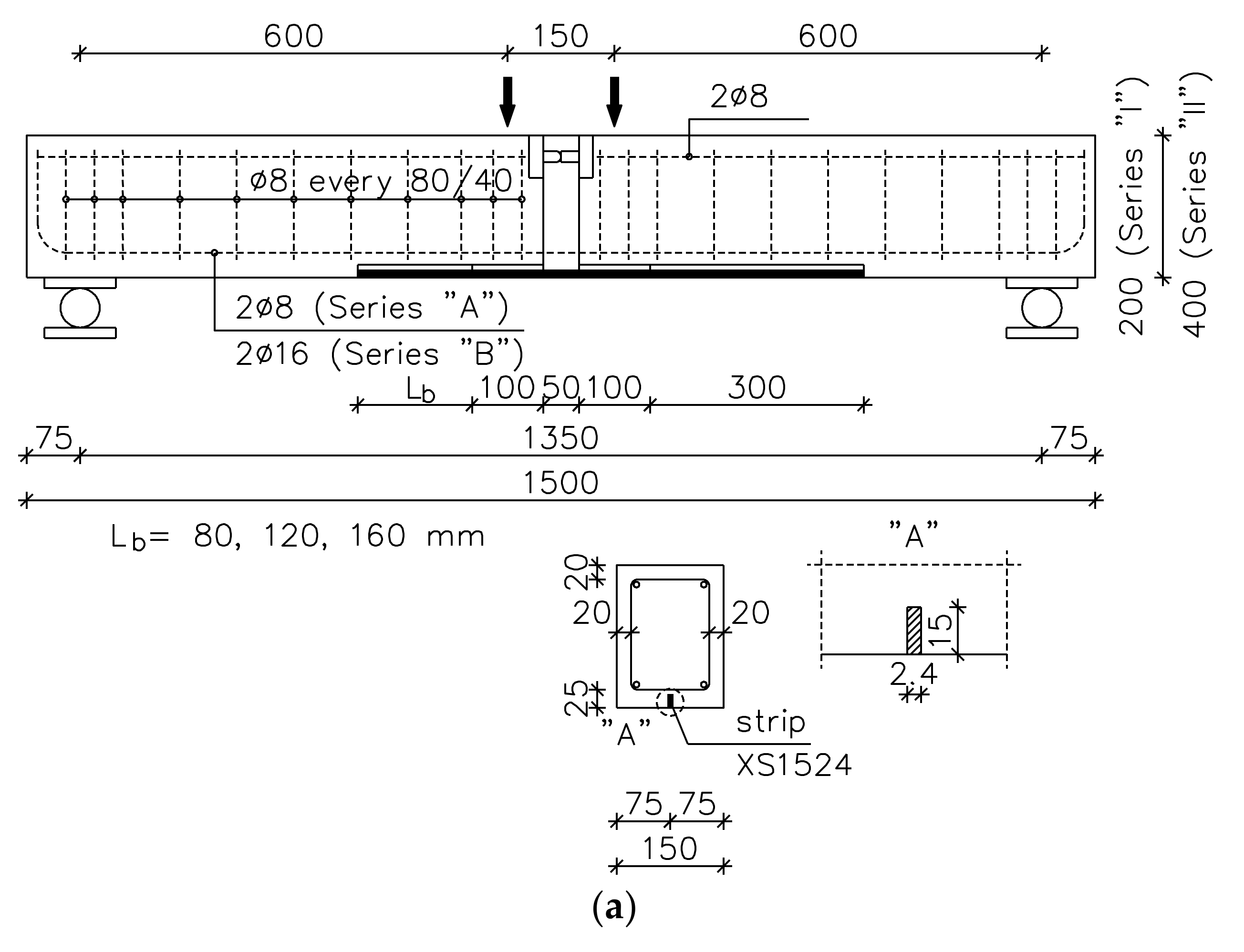
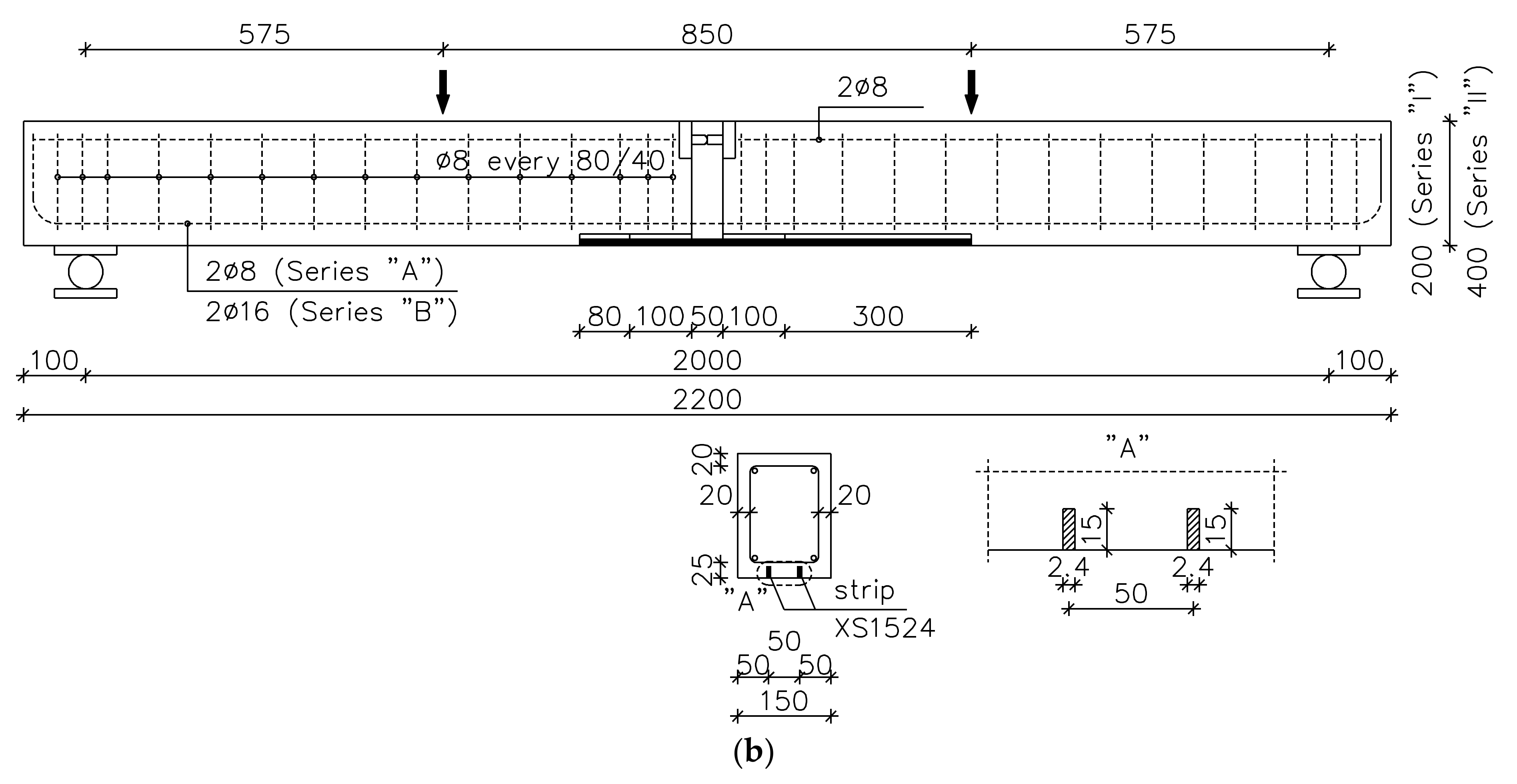
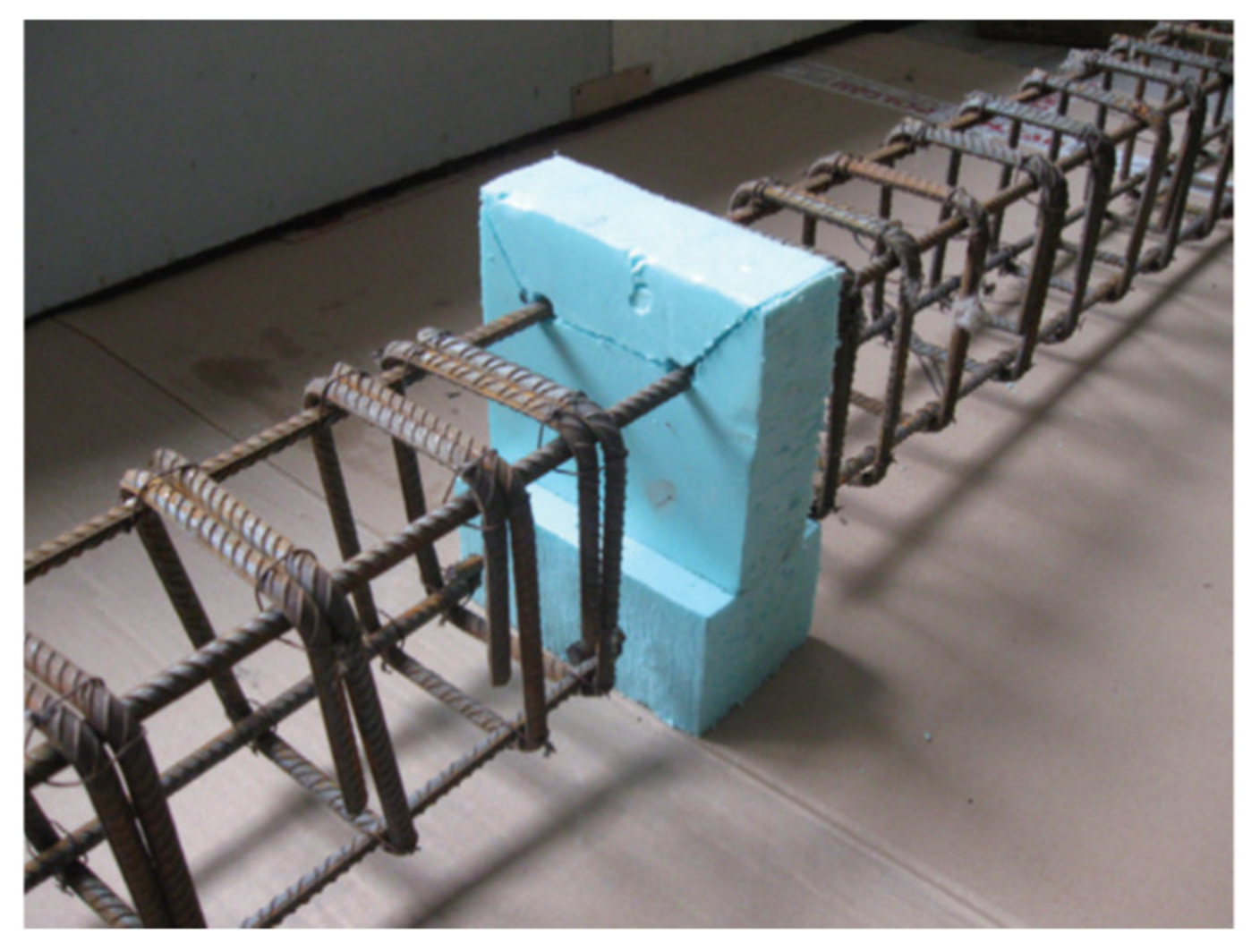
2.2. Test Specimens
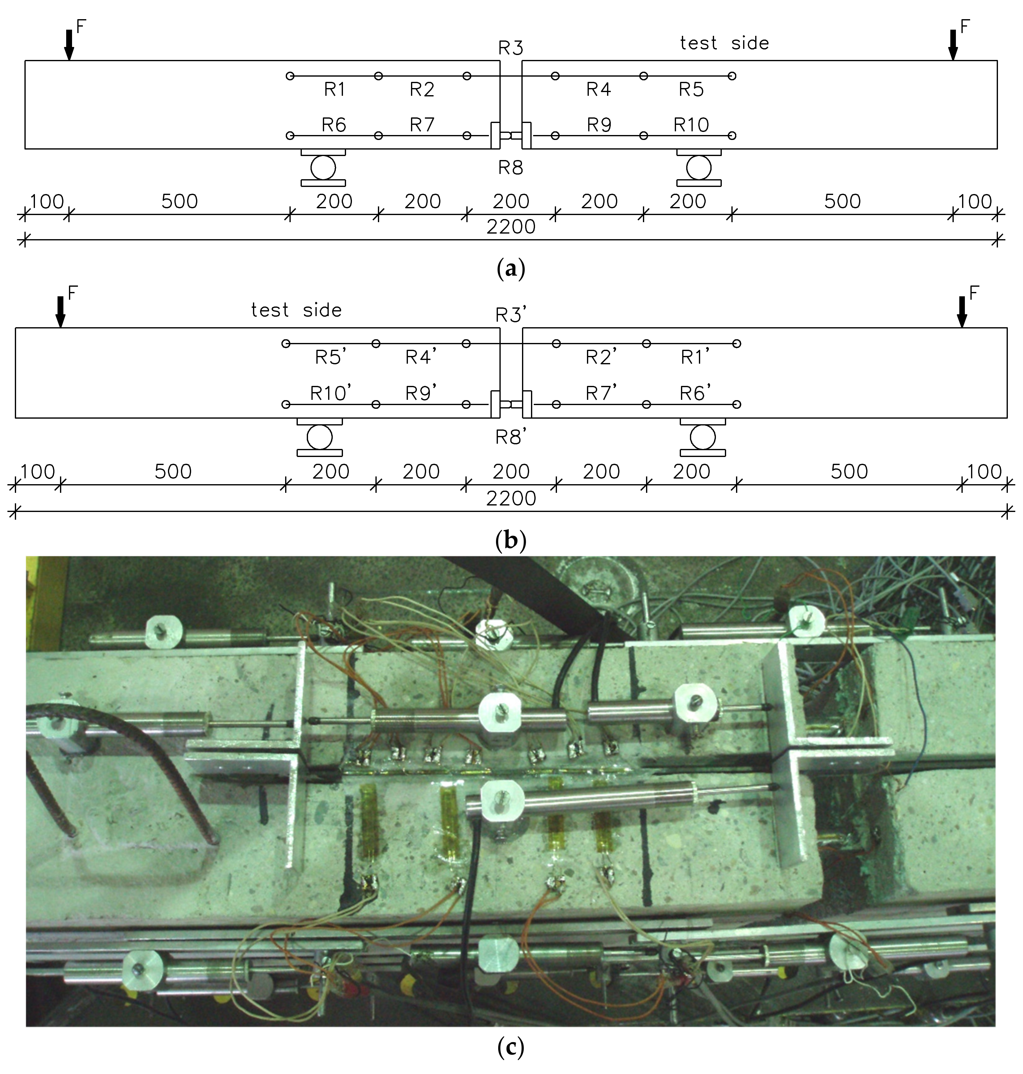
2.3. Instrumentation and Test Set-Up Description
3. Test Results
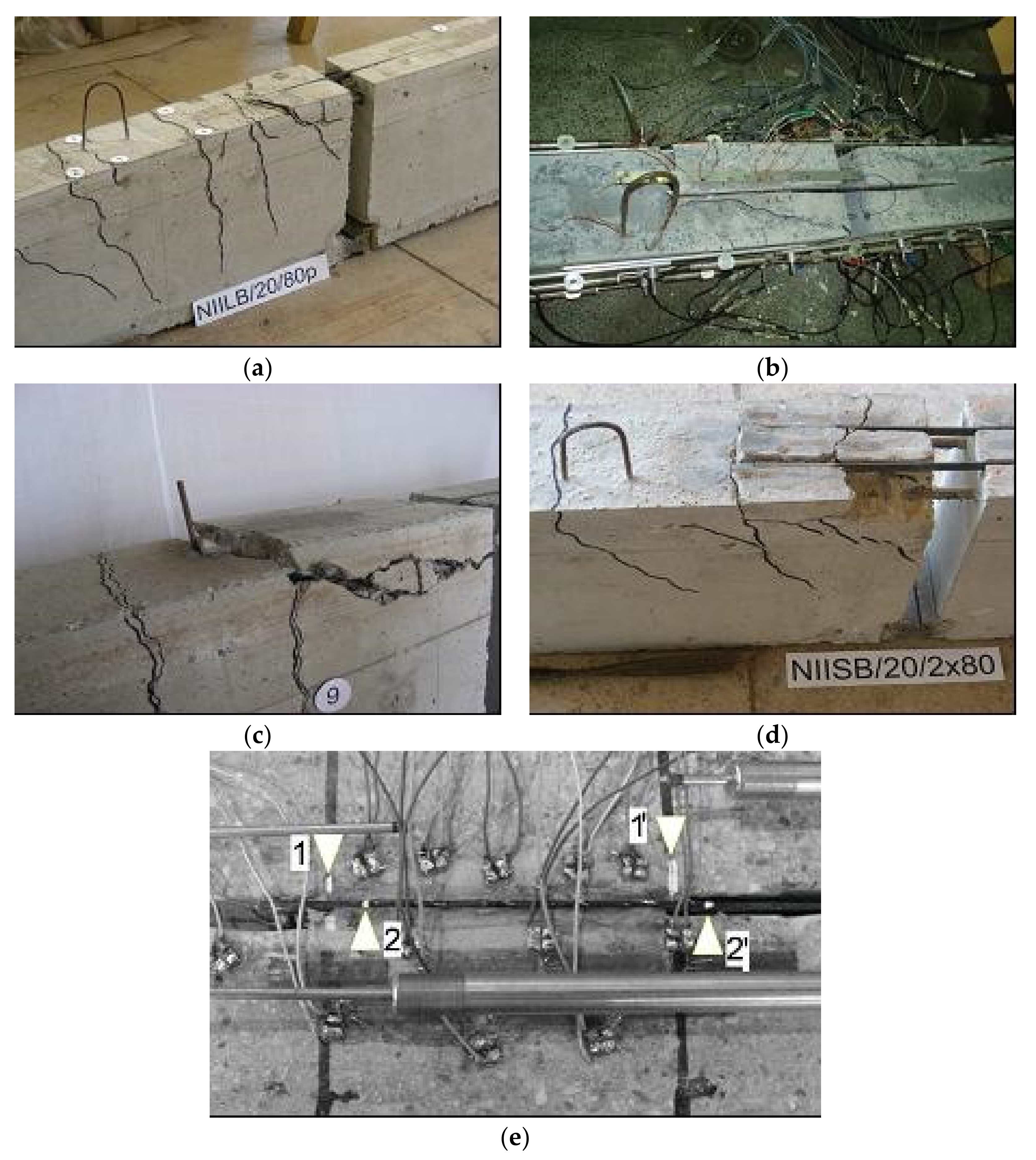
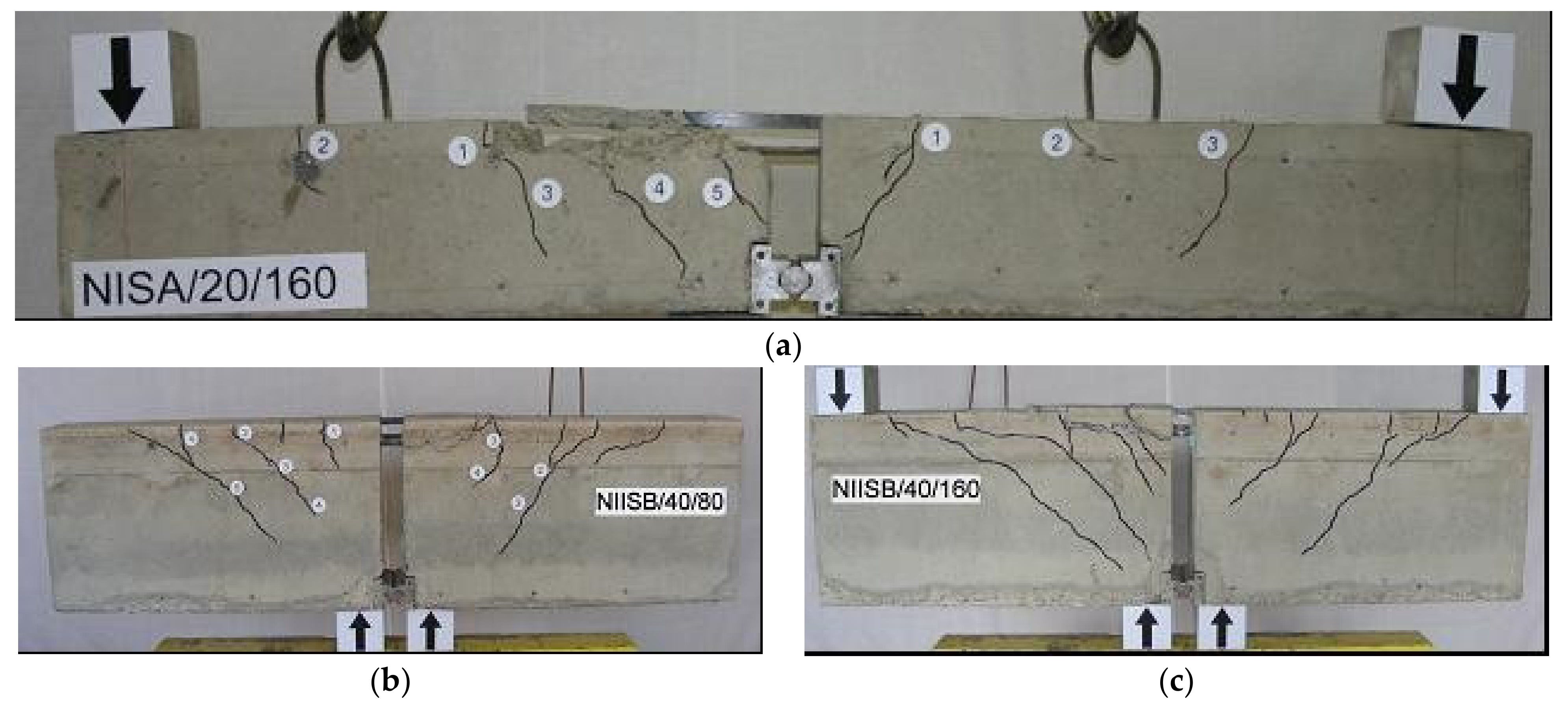
3.1. Failure Modes
3.2. Crack Patterns
3.3. Ultimate Loads
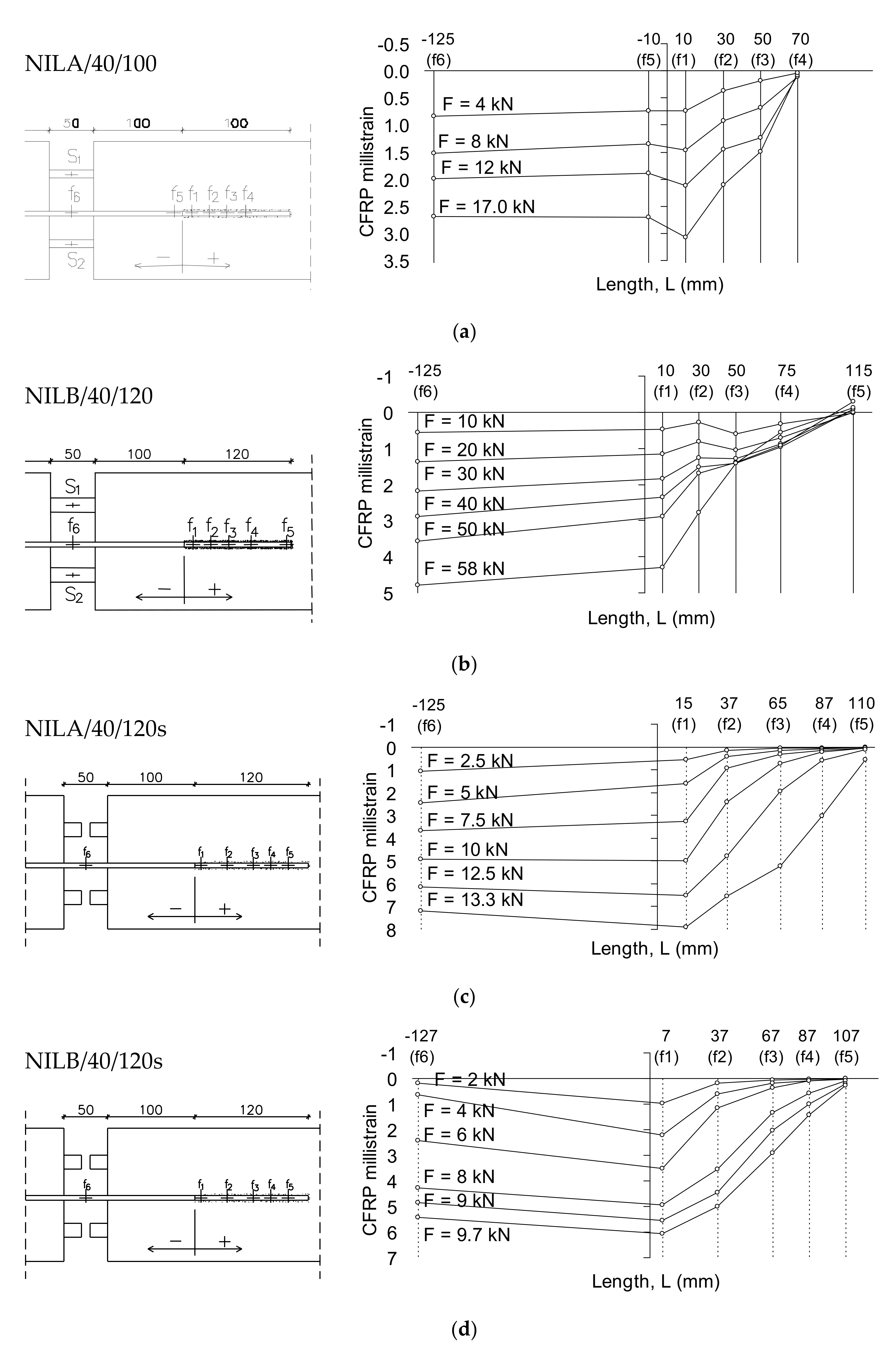
3.4. Debonding Strains and Strain Distributions
4. Finite Element Modelling
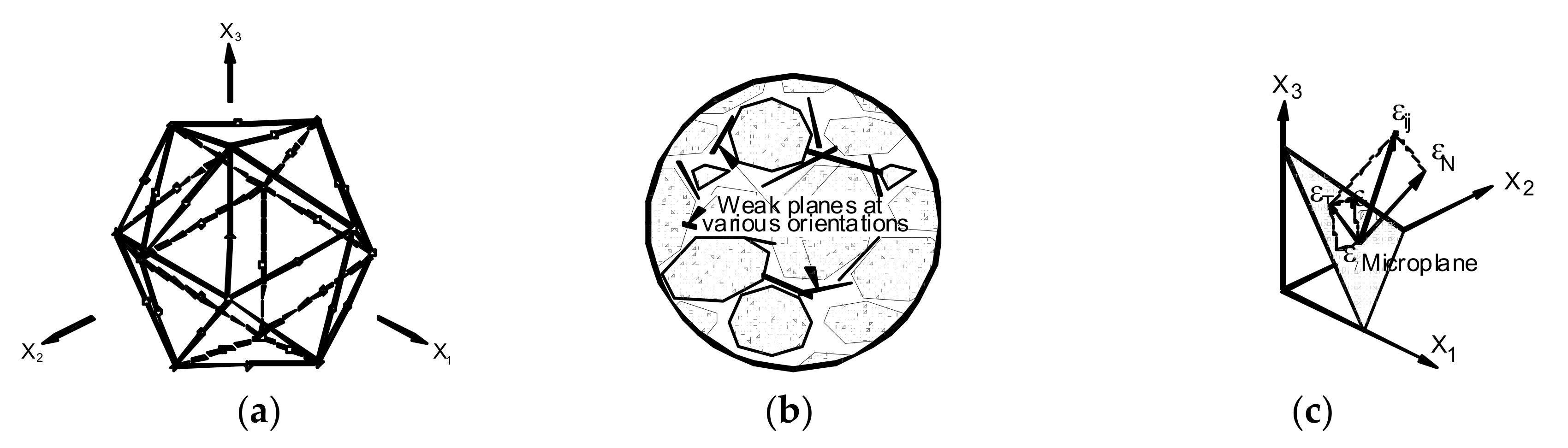
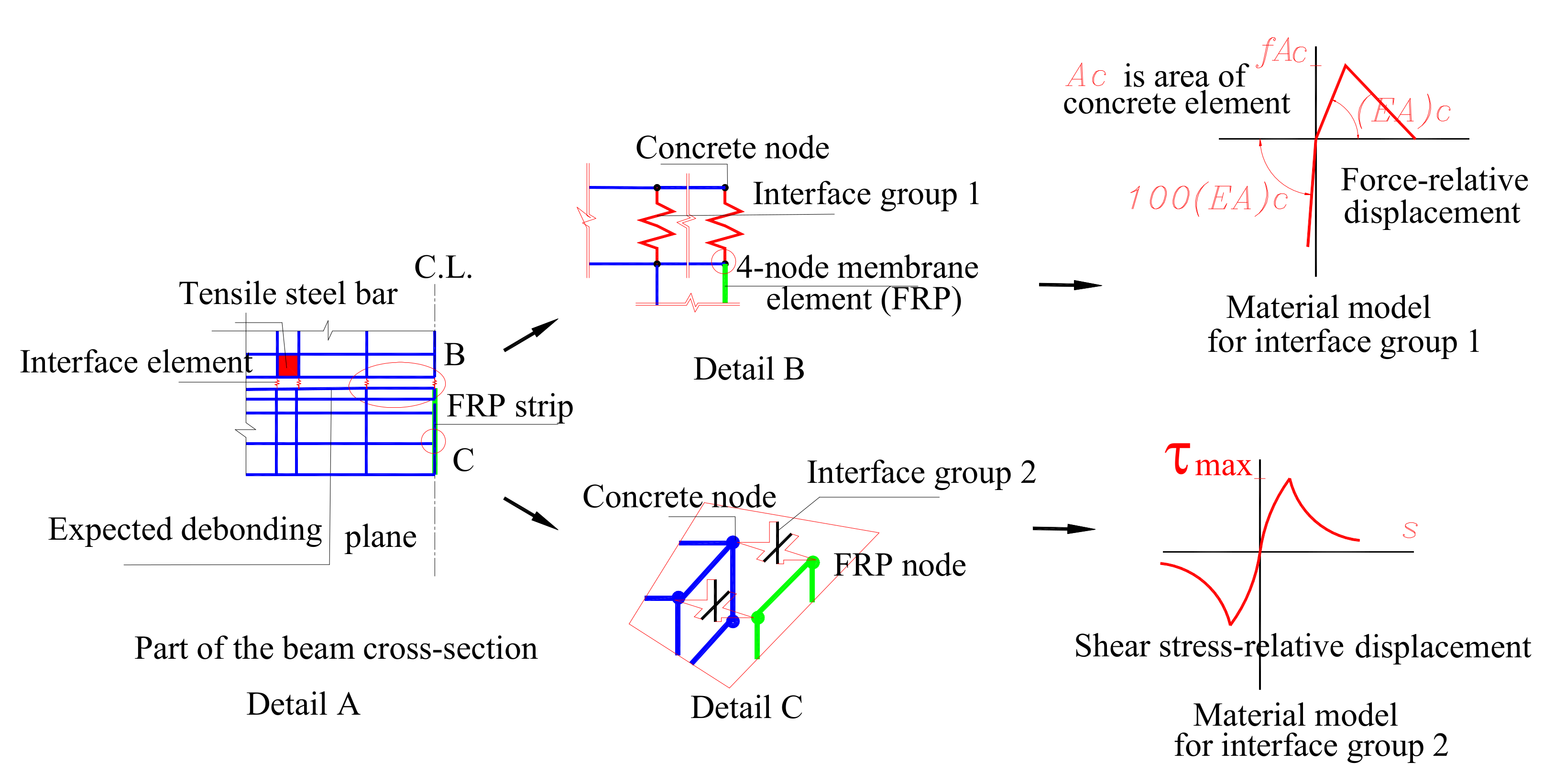
4.1. Material Models for Concrete, Steel and CFRP
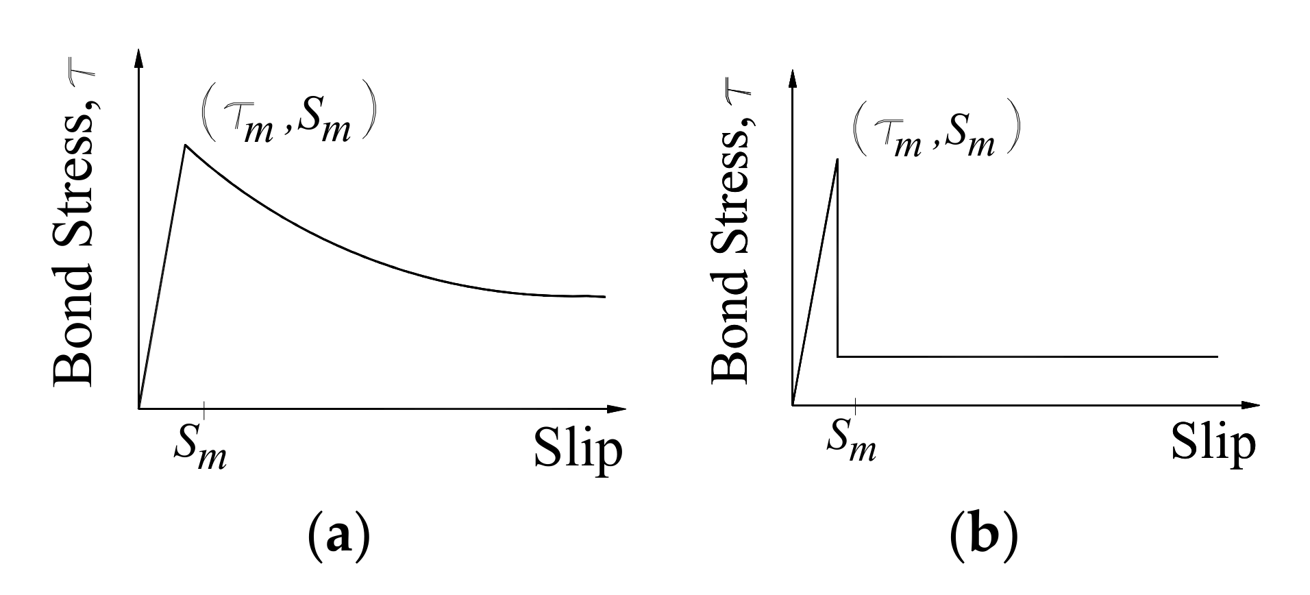
4.2. Interface Model between CFRP and Concrete
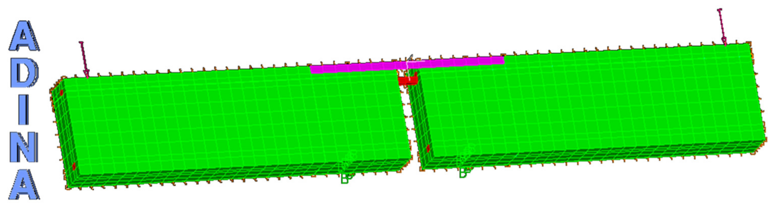
4.3. Modelling of Geometry
5. Numerical Results and Discussion
5.1. Ultimate Loads and Failure Mode
5.2. Axial Strains in NSM CFRP Strips
5.3. Numerical Aspects of the Simulations
6. Conclusions
- –
- The test results confirmed that failure of NSM CFRP-strengthened specimens with continuous steel reinforcement was caused by the steel yielding and the flexural failure modes, rather than bond failure at the CFRP–concrete interface. The mode of failure was distinguished by the initiation of a major flexure crack at the end of the CFRP strip due to yielding of the internal reinforcement at this location, followed by complete debonding of the CFRP strips from the surrounding concrete beam. However, the slippage between the CFRP strips and concrete was observed in the beams with cut bars at the mid-span (specimens with index “s”).
- –
- The enhancement in the ultimate load-carrying capacity of the tested specimens was in the range of 6% to 24% of the corresponding control specimens for the short beams (NIS) with lower reinforcement (2 bars of 8 mm diameter) and in the range of 20% to 73% of the corresponding control specimens for the long beams (NIL) depending on the bond length of the NSM CFRP strips and concrete compressive strength.
- –
- It was unexpected that short strengthened beams with the higher reinforcement ratio (NIIS) failed under lower loading than the reference beam. It confirms that the reason for this failure mode is much stiffer behaviour of the beams reinforced with much higher internal reinforcement that caused such brittle behaviour of the strengthened beams after CFRP debonding.
- –
- The cutting of the longitudinal rebars delayed the debonding of the NSM laminates, thus significantly increasing the CFRP strains at failure. However, the beams with cut steel reinforcement at the mid-span indicated a 57% higher ultimate strain in the strengthening NSM CFRP strip (for the beams NILA/40/120 and NILA/40/120s). However, the ultimate load for the beam NILA/40/120s with cut reinforcement was 82% lower than this one with longitudinal reinforcement.
- –
- A slightly different situation was observed in the short beams with the higher reinforcement (NILB/40/120 and NILB/40/120s). The cutting of the longitudinal bars delayed the debonding of the NSM laminates and significantly increased the CFRP strains’ failure by 76%. However, the ultimate load for the beam with cut reinforcement NILB/40/120s was unexpectedly lower by 452% than this one with longitudinal reinforcement.
- –
- The experimental results showed that the steel reinforcement ratio is the most dominant parameter affecting the bond behaviour between the CFRP strips and concrete. Furthermore, it was observed that the final failure modes are mainly controlled by the effect of the internal steel bars (longitudinal and cut).
- –
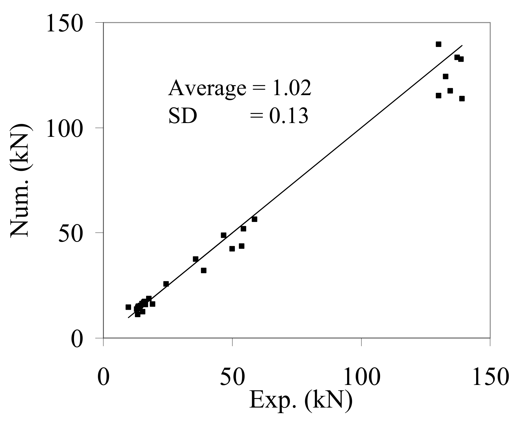
- The proposed finite element model represents an advanced numerical tool based on micromechanics materials. The prediction of the ultimate load-carrying capacities was based on the major discrete crack approach to represent the flexural failure mode. The finite element analysis revealed a good efficiency of the predicted ultimate loads compared to the experimental ones with an average ratio of numerical and experimental maximum load and its standard deviation equal to 1.02 and 0.13, respectively.
- –
- The interfacial stiffness and the bond strength had a small influence on the overall structural stiffness when they were used to constitute the horizontal interface elements. However, they did have a significant effect when they were defined by the interfacial behaviour of interface elements in the vertical direction.
- –
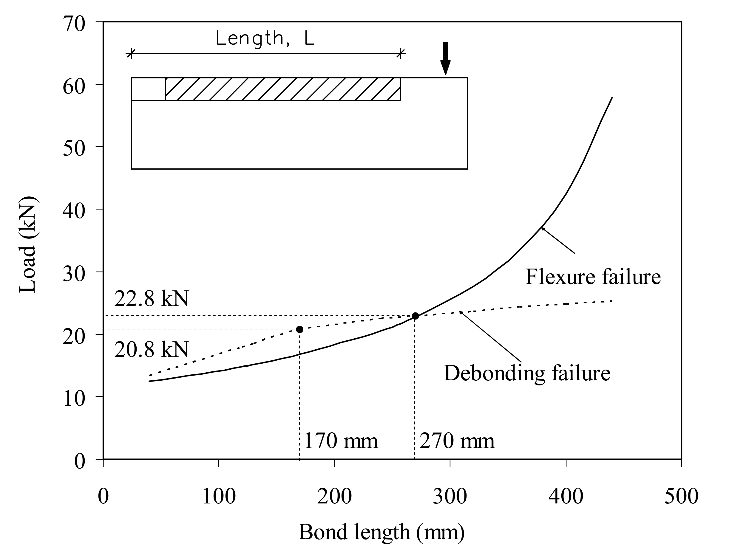
- For the beams with a small bond length and failure due to strip debonding, the material properties of the discrete crack model did not affect the numerical predictions. For the specimens with a bond length higher than 270 mm, the concrete fracture energy significantly affected the ultimate load. The numerical simulations revealed that using the concrete tensile strength to define the concrete–steel bond strength with the discrete crack interface element underestimates the predicted values. The bond strength that gave quite good predictions was between 1.5–2.0 times the concrete tensile strength.
Author Contributions
Funding
Institutional Review Board Statement
Informed Consent Statement
Data Availability Statement
Conflicts of Interest
References
- Nanni, A. Flexural behaviour and design of RC members using FRP reinforcement. J. Struct. Eng. 1993, 119, 44–59. [Google Scholar] [CrossRef]
- Blaschko, M.; Zilch, K. Rehabilitation of concrete structures with CFRP strips glued into slits. In Proceedings of the Twelfth International Conference of Composite Materials, Paris, France, 5–9 July 1999; pp. 1–7. [Google Scholar]
- Carolin, A. Carbon Fibre Reinforced Polymers for Strengthening of Structural Elements. Ph.D. Thesis, Luleå University of Technology, Lulea, Sweden, 2003. [Google Scholar]
- EL-Hacha, R.; Rizkalla, S.H. Near Surface Mounted FRP reinforcements for flexural strengthening of concrete structures. ACI Struct. J. 2004, 101, 717–726. [Google Scholar]
- Barros, J.A.O.; Fortes, A.S. Flexural strengthening of concrete beams with CFRP laminates bonded into slits. Cem. Concr. Compos. 2005, 27, 471–480. [Google Scholar] [CrossRef] [Green Version]
- Sena-Cruz, J.M. Strengthening of concrete structures with near-surface mounted CFRP laminate strips. Ph.D. Thesis, University of Minho, Minho, Portugal, 4 July 2005. [Google Scholar]
- Barros, J.A.O.; Ferreira, D.R.S.M.; Fortes, A.S.; Dias, S.J.E. Assessing the effectiveness of embedding CFRP laminates the near surface for structural strengthening. Constr. Build. Mater. 2006, 20, 478–491. [Google Scholar] [CrossRef] [Green Version]
- Barros, J.A.O.; Dias, S.J.E. Near surface mounted CFRP laminates for shear strengthening of concrete beams. Cem. Concr. Compos. 2006, 283, 276–292. [Google Scholar] [CrossRef] [Green Version]
- Liu, I.S.T.; Oehlers, D.J.; Seracino, R. Tests on the ductility of reinforced concrete beams retrofitted with FRP and steel near-surface mounted plates. J. Compos. Constr. 2006, 102, 106–114. [Google Scholar] [CrossRef]
- De Lorenzis, L.; Miller, B.; Nanni, A. Bond of fibre reinforced polymer laminates to concrete. ACI Mat. J. 2001, 98, 256–264. [Google Scholar]
- Kotynia, R. Analysis of reinforced concrete beams strengthened with near surface mounted FRP reinforcement. Arch. Civ. Eng. 2006, 2, 305–317. [Google Scholar]
- Kotynia, R. Analysis of the flexural response of NSM FRP-strengthened concrete beams. In Proceedings of the 8th International Symposium on Fiber Reinforced Polymer Reinforcement for Reinforced Concrete Structures (FRPRCS-8), Patras, Greece; 2007. [Google Scholar]
- Barros, J.; Kotynia, R. Possibilities and challenges of NSM for the flexural strengthening of RC structures. In Proceedings of the Fourth International Conference on FRP Composites in Civil Engineering CICE2008, Zurich, Switzerland; 2008. [Google Scholar]
- Al-Mahmoud, F.; Castel, A.; François, R.; Tourneur, C. Strengthening of RC members with near-surface mounted CFRP rods. Compos. Struct. 2009, 91, 138–147. [Google Scholar] [CrossRef]
- Al-Mahmoud, F.; Castel, A.; François, R.; Tourneur, C. RC beams strengthened with NSM CFRP rods and modelling of peeling-off failure. Compos. Struct. 2010, 92, 1920–1930. [Google Scholar] [CrossRef]
- Soliman, S.M.; El-Salakawy, E.; Benmokrane, B. Flexural behaviour of concrete beams strengthened with near surface mounted fibre reinforced polymer bars. Can. J. Civ. Eng. 2010, 37, 1371–1382. [Google Scholar] [CrossRef]
- Dalfré, G.M.; Barros, J.A.O. Flexural Strengthening of RC Continuous Slab Strips Using NSM CFRP Laminates. Adv. Struct. Eng. 2011, 14, 1223–1245. [Google Scholar] [CrossRef]
- Abdel Baky, H.; Ebead, U.; Neale, K.W. Flexural and interfacial behaviour of FRP-strengthened reinforced concrete beams. J. Compos. Constr. 2007, 11, 629–639. [Google Scholar] [CrossRef]
- Sharaky, I.A.; Torres, L.; Sallam, H.E.M. Experimental and analytical investigation into the flexural performance of RC beams with partially and fully bonded NSM FRP bars/strips. Compos. Struct. 2015, 122, 113–126. [Google Scholar] [CrossRef]
- Bilotta, A.; Ceroni, F.; Nigro, E.; Pecce, M. Efficiency of CFRP NSM strips and EBR plates for flexural strengthening of RC beams and loading pattern influence. Compos. Struct. 2015, 124, 163–175. [Google Scholar] [CrossRef]
- Hosen, M.A.; Jumaat, M.Z.; Islam, A.S. Side near Surface Mounted (SNSM) technique for flexural enhancement of RC beams. Mater. Des. 2015, 83, 587–597. [Google Scholar] [CrossRef]
- Hosen, M.A.; Jumaat, M.Z.; Alengaram, U.J.; Islam, A.S.; Hashim, H. Near Surface Mounted Composites for Flexural Strengthening of Reinforced Concrete Beams. Polymers 2016, 8, 67. [Google Scholar] [CrossRef] [PubMed] [Green Version]
- Parvin, A.; Shah, T.S. Fiber Reinforced Polymer Strengthening of Structures by Near-Surface Mounting Method. Polymers 2016, 8, 298. [Google Scholar] [CrossRef] [Green Version]
- Zhang, S.S.; Yu, T.; Chen, G.M. Reinforced concrete beams strengthened in flexure with near-surface mounted (NSM) CFRP strips: Current status and research needs. Compos. B 2017, 131, 30–42. [Google Scholar] [CrossRef] [Green Version]
- Sharaky, I.A.; Reda, R.M.; Ghanem, M.; Seleem, M.H.; Sallam, H.E.M. Experimental and numerical study of RC beams strengthened with bottom and side NSM GFRP bars having different end conditions. Constr. Build. Mater. 2017, 149, 882–903. [Google Scholar] [CrossRef]
- Zheng, Y.; Xia, L. Investigation of the ultimate capacity of NSM FRP-strengthened concrete bridge deck slabs. Arab. J. Sci. Eng. 2018, 43, 1597–1615. [Google Scholar] [CrossRef]
- Hosen, M.A.; Jumaat, M.Z.; Alengaram, U.J.; Sulong, N.H.R. CFRP strips for enhancing flexural performance of RC beams by SNSM strengthening technique. Constr. Build. Mater. 2018, 165, 28–44. [Google Scholar] [CrossRef]
- Gravina, R.; Aydin, H.; Visintin, P. Australian Review of near-surface mounted FRP plates in the strengthening of continuous flexural members and bond behavior. J. Civ. Eng. 2018, 16, 158–165. [Google Scholar]
- Astorga, A.; Santa Maria, H.; Lopez, M. Behavior of a concrete bridge cantilevered slab reinforced using NSM CFRP strips. Constr. Build. Mat. 2013, 40, 461–472. [Google Scholar] [CrossRef]
- Teng, J.; De Lorenzis, L.; Wang, B.; Li, R.; Wong, T.; Lam, L. Debonding Failures of RC Beams Strengthened with near Surface Mounted CFRP Strips. J. Compos. Constr. 2006, 10, 92–105. [Google Scholar] [CrossRef]
- De Lorenzis, L.; Teng, J. Near-surface mounted FRP reinforcement: An emerging technique for strengthening structures. Compos. Part B 2007, 38, 119–143. [Google Scholar] [CrossRef]
- Nakaba, K.; Kanakubo, T.; Furuta, T.; Youshizawa, H. Bond behaviour between fibre-reinforced polymer laminates and concrete. ACI Struct. J. 2001, 98, 359–367. [Google Scholar]
- De Lorenzis, L.; Nanni, A. Bond between NSM fibre-reinforced polymer rods and concrete in structural strengthening. ACI Struct. J. 2002, 99, 123–132. [Google Scholar]
- Blaschko, M. Bond behaviour of CFRP strips glued into slits. In Proceedings of the 6th International Symposium FRP Reinforcement for Concrete Structures, FRPRCS-6; Tan, K.H., Ed.; World Scientific Publishing Co.: Singapore, 2003; pp. 205–214. [Google Scholar]
- Hassan, T.; Rizkalla, S. Investigation of bond in concrete structures strengthened with near surface mounted carbon fibre reinforced polymer strips. J. Compos. Constr. 2003, 7, 248–257. [Google Scholar] [CrossRef]
- De Lorenzis, L.; Lundgren, K.; Rizzo, A. Anchorage length of near-surface mounted fibber-reinforced polymer bars for concrete strengthening—Experimental investigation and numerical modeling. ACI Struct. J. 2004, 101, 269–278. [Google Scholar]
- Sena Cruz, J.M.; Barros, J.A.O. Bond between near-surface mounted CFRP laminate strips and concrete. J. Compos. Constr. 2004, 8, 519–527. [Google Scholar] [CrossRef] [Green Version]
- Sena Cruz, J.M.; Barros, J.A.O. Modeling of Bond between near-surface mounted CFRP laminates strips and concrete. Comp. Struct. 2004, 82, 1513–1521. [Google Scholar] [CrossRef] [Green Version]
- Täljsten, B.; Carolin, A.; Nordin, H. Concrete structures strengthened with near surface mounted reinforcement of CFRP. Adv. Struct. Eng. 2003, 6, 201–213. [Google Scholar] [CrossRef]
- Seracino, R.; Saifulnaz, M.R.R.; Oehlers, D.J. Generic debonding resistance of EB and NSM plate-to-concrete joints. J. Compos. Constr. 2007, 11, 62–70. [Google Scholar] [CrossRef]
- Seracino, R.; Jones, N.M.; Page, M.W.; Ali, M.S.S.; Oehlers, D.J. Bond strength of near-surface mounted FRP-to-concrete joints. J. Compos. Constr. 2007, 11, 401–409. [Google Scholar] [CrossRef]
- Shukri, A.A.; Jumaat, M.Z. The tension-stiffening contribution of NSM CFRP to the behavior of strengthened RC beams. Materials 2015, 8, 4131–4146. [Google Scholar] [CrossRef] [PubMed] [Green Version]
- Sharaky, I.; Baena, M.; Barris, C.; Sallam, H.E.M.; Torres, L. Effect of axial stiffness of NSM FRP reinforcement and concrete cover confinement on flexural behaviour of strengthened RC beams: Experimental and numerical study. Eng. Struct. 2018, 173, 987–1001. [Google Scholar] [CrossRef]
- Hosen, A.; Jumaat, M.Z.; Saiful, A.B.M.; Islam, A.S. Inclusion of CFRP-Epoxy Composite for End Anchorage in NSM-Epoxy Strengthened Beams Md. Hindawi Publishing Corporation. Adv. Mater. Sci. Eng. 2015, 2015, 812797. [Google Scholar] [CrossRef] [Green Version]
- RILEM TC9-RC. RILEM Recommendations for the Testing and Use of Constructions Materials; RC 5 Bond test for reinforcement steel. 1. Beam test; E & FN SPON: London, UK, 1982; pp. 213–217. [Google Scholar] [CrossRef]
- Sena-Cruz, J.M.; Barros, J.A.O.; Azevedo, A.F.M.; Gettu, R. Bond behaviour of near-surface mounted CFRP laminate strips under monotonic and cyclic loading. J. Compos. Constr. 2006, 10, 295–303. [Google Scholar] [CrossRef] [Green Version]
- Kotynia, R. Bond between Composite Materials and Concrete in Reinforced Concrete Members Strengthened with CFRP Composites, Report No 16. Experimental Investigations of Concrete Elements and Structures. Department of Concrete Structures, Faculty of Civil Engineering, Architecture and Environmental Engineering, Lodz University of Technology: Lodz, Poland, 2008; p. 64. ISBN 1230-6010. [Google Scholar]
- Kotynia, R. Bond between FRP and concrete in reinforced concrete beams strengthened with near surface mounted and externally bonded reinforcement. Constr. Build. Mater. 2012, 32, 41–54. [Google Scholar] [CrossRef]
- Perera, W.K.K.G.; Ibell, T.J.; Darby, A.P. Bond behaviour and effectiveness of various shapes of NSM CFRP bars. In Proceedings of the 9th International Symposium on Fiber-Reinforced Polymers Reinforcement for Concrete Structures (FRPRCS-9), Sidney, Australia, 13–15 July 2009. [Google Scholar]
- Oehlers, D.J.; Haskett, M.; Wu, C.; Seracino, R. Embedding NSM FRP Plates for Improved IC Debonding Resistance. J. Compos. Constr. 2008, 12, 6. [Google Scholar] [CrossRef]
- Nanni, A.; Bakis, C.E.; Boothby, T.E. Test methods for FRP-concrete systems subjected to mechanical loads: State of the art review. J. Reinf. Plast. Compos. 1995, 14, 524–558. [Google Scholar] [CrossRef]
- Soliman, S. Flexural Behaviour of Reinforced Concrete Beams Strengthened with Near Surface Mounted FRP Bars. Ph.D. Thesis, University of Sherbrooke, Civil Engineering Department, Sherbrooke, QC, Canada, 2008; 182p. [Google Scholar]
- Zhang, S. Behaviour and Modelling of RC Beams Strengthened in Flexure with Near-Surface Mounted FRP Strips. Ph.D. Thesis, Hong Kong Polytechnic University, Hong Kong, 2012; 383p. [Google Scholar]
- Borchert, K.; Zilch, K. Bond behavior of NSM FRP strips in service. Struct. Concr. 2008, 9, 127–142. [Google Scholar] [CrossRef]
- Bianco, V.; Barros, J.; Monti, G. Bond model of NSM-FRP strips in the context of the shear strengthening of RC beams. J. Struct. Eng. 2009, 135, 619–631. [Google Scholar] [CrossRef]
- Savoia, M.; Mazzotti, C.; Ferracuti, B. A new single-shear set-up for stable debonding of FRP-concrete joints. Constr. Build. Mater. 2009, 23, 1529–1537. [Google Scholar]
- Soliman, S.; El-Salakawy, E.; Benmokrane, B. Bond performance of near-surface-mounted FRP bars. J. Compos. Constr. 2010, 15, 103–111. [Google Scholar] [CrossRef]
- Ceroni, F.; Pecce, M.; Bilotta, A.; Nigro, E. Bond behavior of FRP NSM systems in concrete elements. Compos. Part B Eng. 2012, 43, 99–109. [Google Scholar] [CrossRef]
- Lee, D.; Cheng, L.; Hui, J. Bond characteristics of various NSM FRP reinforcements in concrete. J. Compos. Constr. 2012, 17, 117–129. [Google Scholar] [CrossRef]
- Yuan, H.; Lu, X.; Hui, D.; Feo, L. Studies on FRP-concrete interface with hardening and softening bond–slip law. Compos. Struct. 2012, 94, 3781–3792. [Google Scholar] [CrossRef]
- Sharaky, I.A.; Torres, L.; Baena, M.; Miàs, C. An experimental study of different factors affecting the bond of NSM FRP bars in concrete. Compos. Struct. 2013, 99, 350–365. [Google Scholar] [CrossRef]
- Seo, S.Y.; Feo, L.; Hui, D. Bond strength of near surface-mounted FRP plate for retrofit of concrete structures. Compos. Struct. 2013, 95, 719–727. [Google Scholar] [CrossRef]
- Al-Saadi, N.T.K.A.; Mohammed, A.R.; Al-Mahaidi, R.; Sanjayan, J. A state-of-the-art review: Near-surface mounted FRP composites for reinforced concrete structures. Constr. Build. Mater. 2019, 209, 748–769. [Google Scholar] [CrossRef]
- Funari, M.F.; Verre, S. The Effectiveness of the DIC as a Measurement System in SRG Shear Strengthened Reinforced Concrete Beams. Crystals 2021, 11, 265. [Google Scholar] [CrossRef]
- Niu, H.; Wu, Z. Effects of FRP-concrete interface bond properties on the performance of RC beams strengthened in flexure with externally bonded FRP sheets. J. Mat. Civ. Eng. 2006, 18, 723–731. [Google Scholar] [CrossRef] [Green Version]
- Wu, Z.; Hemdan, S. Debonding in FRP-strengthened flexural members with different shear-span ratios. In Proceedings of the 7th International Symposium on Fibre-Reinforced Composite Reinforcement for Concrete Structures, (FRPRCS)-7, New Orleans, LA, USA; 2005. SP-230-24. pp. 411–426. [Google Scholar]
- Kishi, N.; Zhang, G.; Mikami, H. Numerical cracking and debonding analysis of RC beams reinforced with FRP sheet. J. Compos. Constr. 2005, 9, 507–514. [Google Scholar] [CrossRef]
- Rahimi, H.; Hutchinson, A. Concrete beams strengthened with externally bonded FRP plates. J. Compos. Constr. 2001, 5, 44–56. [Google Scholar] [CrossRef]
- Vecchio, F.J. Reinforced concrete membrane element formulations. J. Struct. Eng. 1990, 116, 730–750. [Google Scholar] [CrossRef]
- ADINA. Automatic Dynamic Incremental Nonlinear Analysis: Finite Element Software, Version 8.4; ADINA R & D Inc.: Watertown, MA, USA, 2004. [Google Scholar]
- Bažant, Z.P.; Caner, F.C.; Carol, I.; Adley, M.D.; Akers, S.A. Microplane model M4 for concrete. I: Formulation with work-conjugate deviatoric stress. J. Eng. Mech. 2000, 126, 944–953. [Google Scholar] [CrossRef] [Green Version]
- Caner, F.C.; Bažant, Z.P. Microplane model M4 for concrete, II: Algorithm and calibration. J. Eng. Mech. 2000, 126, 954–961. [Google Scholar] [CrossRef]
- Feenstra, P.H. Computational Aspects of Biaxial Stress in Plain and Reinforced Concrete. Ph.D. Thesis, Delft University of Technology, South Holland, The Netherlands, 1993. [Google Scholar]
- Abdel Baky, H.M. Nonlinear Micromechanics-Based Finite Element Analysis of the Interfacial Behaviour of FRP-Strengthened Reinforced Concrete Beams. Ph.D. Thesis, University of Sherbrooke, Civil Engineering Department, Sherbrooke, QC, Canada, 2008; 220p. [Google Scholar]
- Abdel Baky, H.M.; Neale, K.W.; Ebead, U.A. Nonlinear Micromechanics–Based FE Analysis of FRP-Strengthened Concrete Structures. In Proceedings of the Fourth International Conference on FRP Composites in Civil Engineering; 2008. [Google Scholar]
- Kotynia, R.; Abdel Baky, H.; Neale, K.W.; Ebead, U. Flexural strengthening of RC beams with externally bonded CFRP systems: Test results and 3-D nonlinear finite element analysis. J. Compos. Constr. 2008, 12, 190–201. [Google Scholar] [CrossRef]

| Component | Amount (kg/m3) | |
|---|---|---|
| Coarse aggregate | 625 | 812 |
| Fine aggregate | 625 | 541 |
| Cement | 300 | 400 |
| Water/Cement ratio | 0.6 | 0.43 |
| No | Series ID | Steel Reinforcement Ratio | Beam ID | MPa | MPa | mm | kN | kN | |||
|---|---|---|---|---|---|---|---|---|---|---|---|
| 1 | NIS | 2#8 | NISA/20 * | 24.50 | – | – | – | 14.16 | – | – | – |
| 2 | NISA/20/85 | 22.30 | 1.6 | 85 | 13.27 | 0.94 | 0 | 0.00208 | |||
| 3 | NISA/20/120 | 21.30 | 2.0 | 120 | 13.40 | 15.21 | 1.07 | 0.00287 | 0.00260 | ||
| 4 | NISA/20/130 | 23.00 | 1.6 | 130 | 14.98 | 14.98 | 1.06 | 0.00255 | 0.00193 | ||
| 5 | NISA/20/160 | 21.30 | 2.0 | 160 | 15.20 | 15.63 | 1.10 | 0.00286 | 0.00258 | ||
| 6 | NISA/30 | 32.50 | – | 30 | 10.70 | 12.89 | – | 0.00273 | – | ||
| 7 | NISA/30/80 | 32.50 | – | 80 | 15.60 | 15.96 | 1.24 | 0.00284 | 0.00264 | ||
| 8 | NISA/30/120 | 32.50 | – | 120 | 11.01 | 14.40 | 1.12 | 0.00276 | 0.00316 | ||
| 9 | 2#16 | NISB/20 * | 19.84 | 2.1 | – | 32.20 | 49.91 | – | 0.00268 | – | |
| 10 | NISB/20/85 | 19.84 | 2.1 | 85 | 32.21 | 38.92 | 0.78 | 0.00268 | 0.00293 | ||
| 11 | NISB/20/130 | 19.84 | 2.1 | 130 | 34.76 | 35.79 | 0.72 | 0.00285 | 0.00264 | ||
| 12 | NIIS | 2#16 | NIISB/40/80 | 41.58 | 3.8 | 80 | 110.00 | 130.00 | – | 0.00245 | 0.00337 |
| 13 | NIISB/40/2 × 80 | 41.19 | 3.8 | 80 | 129.9 | 129.99 | – | 0.00234 | 0.00198 (0.00246) | ||
| 14 | NIISB/40/120 | 41.19 | 4.4 | 120 | 116.18 | 137.20 | – | 0.00265 | 0.00351 | ||
| 15 | NIISB/40/160 | 41.19 | 4.4 | 160 | 119.47 | 138.65 | – | 0.00286 | 0.00416 | ||
| 16 | NIL | 2#8 | NILA/40 * | 38.30 | 3.2 | – | 10.98 | 14.01 | – | 0.00275 | – |
| 17 | NILA/40/100 | 41.75 | 3.8 | 100 | 12.00 | 16.29 | 1.20 | 0.00286 | 0.00272 | ||
| 18 | NILA/40/120 | 38.50 | 3.4 | 120 | 19.00 | 24.30 | 1.73 | 0.0029 | 0.00502 | ||
| 19 | NILA/40/160 | 38.50 | 3.4 | 160 | 16.28 | 17.64 | 1.26 | 0.00273 | 0.00282 | ||
| 20 | NILA/40/120s | 45.00 | 3.9 | 120 | – | 13.33 | – | – | 0.00791 | ||
| 21 | NILA/50 | 47.50 | 2.8 | – | 11.24 | 13.60 | – | 0.00244 | – | ||
| 22 | NILA/50/2 × 80 | 47.50 | 3.3 | 80 | 18.07 | 19.05 | 1.40 | 0.00281 | 0.00263 (0.00240) | ||
| 23 | 2#16 | NILB/40 * | 38.30 | 3.3 | – | 35.00 | 46.61 | – | 0.00424 | – | |
| 24 | NILB/40/90 | 37.67 | 3.1 | 90 | 40.00 | 54.33 | 1.17 | 0.00281 | 0.00391 | ||
| 25 | NILB/40/120 | 37.67 | 3.1 | 120 | 40.04 | 53.60 | 1.15 | 0.00275 | 0.00345 | ||
| 26 | NILB/40/130 | 43.70 | – | 130 | 50.75 | 58.60 | 1.26 | 0.00311 | 0.00358 | ||
| 27 | NILB/40/120s | 43.70 | – | 120 | – | 9.70 | – | – | 0.00606 | ||
| 28 | NIIL | 2#16 | NIILB/40/80 | 34.32 | 4.0 | 80 | 115.00 | 139.07 | – | 0.00273 | 0.00464 |
| 29 | NIILB/40/2 × 80 | 34.32 | 3.3 | 80 | 130.31 | 134.48 | – | 0.00249 | 0.00274 (0.00325) | ||
| 30 | NIILB/40/120 | 38.80 | 3.3 | 120 | 132.74 | 132.74 | – | 0.00305 | 0.00358 |
| Diameter (mm) | |||
|---|---|---|---|
| 8 | 207 | 637 | 543 |
| 16 | 209 | 636 | 542 |
| Type | Width | Thickness | |||
|---|---|---|---|---|---|
| XS1.524 | 15.10 | 2.41 | 36.39 | 169.4 | 0.0112 |
| No | Beam ID | (MPa) | (mm) | (kN) | |
|---|---|---|---|---|---|
| 1 | NISA/20 * | - | - | 14.00 | 1.01 |
| 2 | NISA/20/85 | 6.44 | 0.0663 | 11.18 | 1.19 |
| 3 | NISA/20/120 | 6.14 | 0.0651 | 12.48 | 1.22 |
| 4 | NISA/20/130 | 6.44 | 0.0663 | 16.35 | 0.92 |
| 5 | NISA/20/160 | 6.14 | 0.0651 | 16.96 | 0.92 |
| 6 | NISA/30 | - | - | 13.75 | 0.94 |
| 7 | NISA/30/80 | 7.96 | 0.0721 | 17.34 | 0.92 |
| 8 | NISA/30/120 | 7.96 | 0.0721 | 15.45 | 0.93 |
| 9 | NISB/20 * | - | - | 42.41 | 1.18 |
| 10 | NISB/20/85 | 5.87 | 0.0640 | 32.10 | 1.21 |
| 11 | NISB/20/130 | 5.87 | 0.0640 | 37.50 | 0.95 |
| 12 | NIISB/40/80 | 9.26 | 0.0767 | 139.70 | 0.93 |
| 13 | NIISB/40/2 × 80 | 9.21 | 0.0766 | 115.26 | 1.13 |
| 14 | NIISB/40/120 | 9.21 | 0.0766 | 133.43 | 1.03 |
| 15 | NIISB/40/160 | 9.21 | 0.0766 | 132.60 | 1.05 |
| 16 | NILA/40 * | - | - | 15.04 | 0.93 |
| 17 | NILA/40/90 | 9.28 | 0.0768 | 15.89 | 1.03 |
| 18 | NILA/40/120 | 8.84 | 0.0752 | 25.71 | 0.95 |
| 19 | NILA/40/130 | 8.84 | 0.0752 | 18.75 | 0.94 |
| 20 | NILA/40/120s | 9.72 | 0.0783 | 14.59 | 0.91 |
| 21 | NILA/50 | - | - | 15.11 | 0.90 |
| 22 | NILA/50/2 × 80 | 10.04 | 0.0795 | 16.14 | 1.18 |
| 23 | NILB/40 * | - | - | 48.87 | 0.95 |
| 24 | NILB/40/90 | 8.72 | 0.0748 | 51.95 | 1.05 |
| 25 | NILB/40/120 | 8.72 | 0.0748 | 43.69 | 1.23 |
| 26 | NILB/40/130 | 9.55 | 0.0777 | 56.48 | 1.04 |
| 27 | NILB/40/120s | 9.55 | 0.0777 | 14.61 | 0.66 |
| 28 | NIILB/40/80 | 8.24 | 0.0731 | 113.80 | 1.22 |
| 29 | NIILB/40/2 × 80 | 8.24 | 0.0731 | 117.54 | 1.14 |
| 30 | NIILB/40/120 | 8.88 | 0.0754 | 124.35 | 1.07 |
Publisher’s Note: MDPI stays neutral with regard to jurisdictional claims in published maps and institutional affiliations. |
© 2021 by the authors. Licensee MDPI, Basel, Switzerland. This article is an open access article distributed under the terms and conditions of the Creative Commons Attribution (CC BY) license (https://creativecommons.org/licenses/by/4.0/).
Share and Cite
Kotynia, R.; Baky, H.A.; Neale, K.W. Bond Behaviour of Near-Surface Mounted Strips in RC Beams—Experimental Investigation and Numerical Simulations. Materials 2021, 14, 4362. https://doi.org/10.3390/ma14164362
Kotynia R, Baky HA, Neale KW. Bond Behaviour of Near-Surface Mounted Strips in RC Beams—Experimental Investigation and Numerical Simulations. Materials. 2021; 14(16):4362. https://doi.org/10.3390/ma14164362
Chicago/Turabian StyleKotynia, Renata, Hussien Abdel Baky, and Kenneth W. Neale. 2021. "Bond Behaviour of Near-Surface Mounted Strips in RC Beams—Experimental Investigation and Numerical Simulations" Materials 14, no. 16: 4362. https://doi.org/10.3390/ma14164362
APA StyleKotynia, R., Baky, H. A., & Neale, K. W. (2021). Bond Behaviour of Near-Surface Mounted Strips in RC Beams—Experimental Investigation and Numerical Simulations. Materials, 14(16), 4362. https://doi.org/10.3390/ma14164362