Abstract
Ceramic foams were fabricated without using melting pots through the direct foaming of compacted powder mixtures of commercial quartz (SiO2) with fluxing agents (Na2CO3 and CaO) and a foaming agent (Na2SiO3·5H2O) at a relatively low temperature range (850−870 °C). The effects of the pressing pressure of the powders, the foaming time, foaming temperature, and mixture content were evaluated. The obtained cellular solid materials presented an acceptable volumetric expansion at a pressing pressure of 4 t. The materials only presented porosity at a minimum temperature of 850 °C and at a minimum time of 30 min. All the foamed samples showed an acceptable symmetric expansion and non-appreciable fissures. The study of the mixture content through the statistical software MODDE® shows that the porosity of the samples was principally affected by the Na2SiO3 content and the foaming temperature. The samples obtained at the optimum controlling factors proposed by this statistical software presented an apparent density, porosity, and mechanical strength of 1.09 ± 0.03 g/cm3, 56.01% ± 1.12%, and 3.90 ± 0.16 MPa, respectively. Glass and ceramics foams such as those obtained in this work become attractive as insulation materials in applications where high temperatures occur due to their higher melting points.
1. Introduction
Ceramic materials with the presence of porosity with any fraction, shape and size can be considered as cellular ceramics [1]. Different methodologies to obtain cellular ceramics have been reviewed [1,2]. Studart et al. have classified the most common processing routes to elaborate macroporous ceramics into three categories: direct foaming, replica, and sacrificial template methods [2]. The former is the most straightforward category for the preparation of cellular ceramics. Within this category, the sintering of powder mixtures that incorporate a foaming agent has been the most common processing route to make these porous ceramic materials, because the porosity and the pore structure can be easily controlled by adjusting the initial composition of the powder mixture [3,4]. The powder mixture is heated above its softening temperature, resulting in the sintering of a solid cellular ceramic because of the release of gas from the foaming agent.
These ceramic foams have a wide range of applications, especially for high temperatures and corrosive environments, such as separation process (filtration), thermal insulation, and support for catalysis reactions, due to their unique properties such as low densities, low thermal conductivity, thermal-shock resistance, and excellent dielectric properties [5]. However, their use has been limited to industrial applications because of the high cost of production associated with the high energy consumption and the elevated price of raw materials [6]. In recent years, another disadvantage to the manufacture of cellular ceramics is the use of foaming agents that generate environmental critical gases (e.g., CO, CO2, SO2), such as carbon and sulfated based agents [7].
In order to overcome these drawbacks to the production of glass-ceramic foams, it is necessary to use inexpensive raw materials, diminish the energy consumption, and use alternative foaming agents that do not generate environmental critical gases through oxidation reactions or thermal decomposition [2,7,8,9,10,11]. One inexpensive raw material used to produce cellular ceramics is the conventional quartz [12]. The mixture of quartz with Na2CO3 and CaO as fluxing agents [1,3,4] and Na2SiO3·5H2O as a foaming agent [13] could be directly foamed using a powder foaming method at low temperatures (800–900 °C) reducing the production of environmental critical gases and the cost of the production process [14]. Hesky et al. [7] classified hydrated sodium silicate as an environmentally friendly foaming agent, since during the foaming process, it releases water vapor instead of carbon dioxide. This study aims to research the feasibility of obtaining symmetric silica foams using compacted mixtures of these raw materials at low temperatures without using melting pots and evaluate the effect of the foaming temperature, pressing pressure, foaming time, and powder mix composition on the characteristics of quartz foams obtained in the presence of sodium silicate as an environmentally friendly foaming agent.
2. Materials and Methods
2.1. Equipment
A disk pulverizer, Bico (Burbarnk, CA, USA) and sieve shaker RX-29-10, Ro-Tap (W.S.Tyler, Mentor OH, USA) were used to prepare a sample of quartz with a size below mesh #200 (74 µm) in order to make a granulometric analysis of this sample. A semi-analytical balance BXX22, Boeco, and overhead stirrer OSD-20, Boeco (Hamburg, Germany) coupled with a Teflon impeller (4-flat-blade), hydraulic press TY12002, Torin (Ontario, CA, USA) and muffle MF10-12G, Biobase (Shandong, China) were employed to elaborate the ceramic foams. Finally, a 50 mL Pycnometer, XRF analyzer Niton XL3t, Thermo Fisher Scientific (Waltham, MA, USA), and CBR loading press 34-T0102/A (Milan, Italy) were used for the quartz and foam characterization.
2.2. Materials
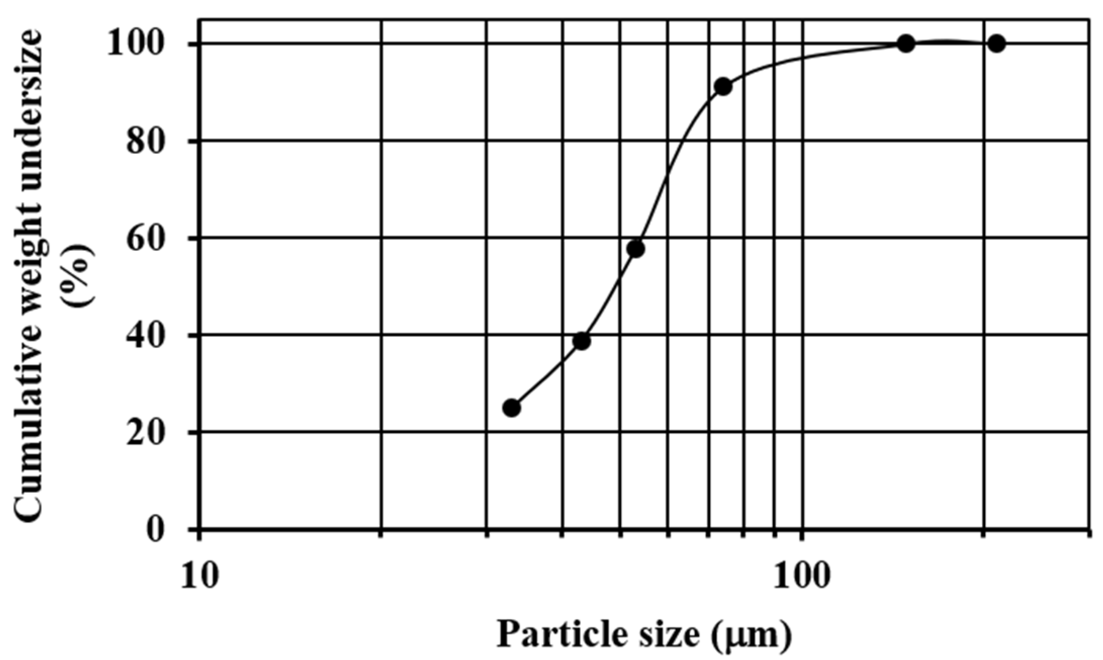
Commercial quartz (SiO2) with a particle size in the range of 3–5 mm was pulverized and sieved until almost all of the sample was below mesh #200 (74 µm). The sieving process was carried out using ASTM sieves (#70, #100, #200, #270, #325 and #400) and a sieve shaker (Ro-Tap). Figure 1 shows the granulometric analysis of the pulverized quartz, where it is observed that the median size (X50) of the sample was about 50 µm, the 80% passing size (X80) was about 70 µm, and the 33.2%w of the material was retained on mesh #270 (53 µm).
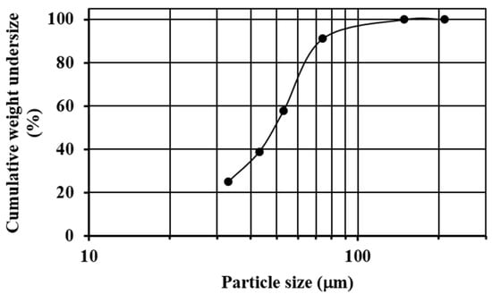
Figure 1.
Sieve analysis of the pulverized quartz.
Table 1 presents the X-ray fluorescence analysis (FRX) realized for the obtained pulverized quartz. Data shows that the sample is mainly composed of silicon. A quartz sample purely composed of SiO2 has an elemental composition of 46.74% of Si and 53.26% of O2. The presence of the other elements and the over-content of silicon indicate the existence of other mineral phases as complex silicates.

Table 1.
Chemical composition of the pulverized quartz.
Sodium silicate pentahydrate (Na2SiO3·5H2O) was used as a foaming agent, and sodium carbonate (Na2CO3) and calcium oxide (CaO) were used as fluxing agents. All materials were purchased from Winkler (Santiago, Chile) with exception of the calcium oxide that was purchased from Dideval (Santiago, Chile). Distilled water was used for all of the experiments in this work.
2.3. Process of Elaboration of Ceramic Foams
Powder quartz was first mechanically blended with solid fluxing agents (Na2CO3 and CaO) for 5 min. Then an aqueous solution of the foaming agent Na2SiO3·5H2O (200 g/L) was added slowly to the solid blend under continuous stirring for 15 min. The wet mixture was poured into a steel mold (4 cm × 4 cm × 7 cm) and pressed for 3 min. This compacted mixture (no melting pot) was sintered and foamed at a determined temperature with a sintering rate of 8.33 °C/min, and then cooled. The cooling rate from the foaming temperature to 600 °C was 5.55 °C/min. From 600 °C, the foams were cooled at room temperature. To determine the minimum time, temperature, and pressing pressure, at which porosity and a symmetric expansion of the foamed materials are produced, these factors were varied according to Table 2.

Table 2.
Evaluated values to determine the minimums at which porosity and a symmetric expansion are produced.
With these minimum values established, the effect of the powder mix composition and temperature on the porosity formation were evaluated according to an experimental design carried out with MODDE® (Umetrics, Sweden). The ranges and fixed values of this experimental design are shown in Table 3.

Table 3.
Evaluated values to determine the minimums at which porosity and a symmetric expansion are produced.
2.4. Ceramic Foams Characterization
The obtained cellular solids were characterized determining their apparent density , real density , porosity percentage , volumetric expansion , loss of weight , mean pore size (), and estimated pore diameter ().
The apparent density was calculated with the weight and volume of a cubic piece of each cellular solid according to Equation (1).
where and are the weight and volume of a cubic piece. To calculate the real density, this cubic piece was pulverized, and the powder density was measured using a pycnometer according to Equation (2).
where is the weight of the empty pycnometer, the weight of the empty pycnometer plus powder, weight of the empty pycnometer plus water, and the weight of the empty pycnometer plus powder and water. Porosity was calculated according to Equation (3).
The volumetric expansion and loss of weight of the cellular solids were calculated according to Equations (4) and (5).
where and are the volume and weight of the compacted mixture, and and are the volume and weight of the sintered and foamed materials. The measurements of the characteristic parameters of the samples obtained according to Table 2 were done in duplicate.
2.5. Computational Tools
MODDE® was used to make a multilevel quadratic design in order to evaluate the effect of the mixture composition and the temperature on the structure of the foamed materials. Considering the ranges and fixed values from Table 3, a total of twenty-six experiments were proposed, whose values are shown in detail in Table 4. As can be seen in the table, four experiments are identical (temperature of 860 °C) in order to check if the experimental design was proposed correctly and to calculate the standard deviation (SD). All the controlled factors and responses were simultaneously calibrated using partial least squares regression (PLSC).

Table 4.
Essay proposed by MODDE® in order to determine the minimums at which porosity and a symmetric expansion are produced.
In addition, ImageJ® (National Institutes of Health, Bethesda, MD, USA) was used to estimate the mean pore size of the foamed materials. First, images of the cross-sections of the foams with a calibration scale (a rule) were opened. A straight line onto the rule with a defined distance was drawn and was selected to set the scale (see Figure 2a). Then, the images were transformed to 8-bit grayscale images, and the thresholding adjustment was applied to them. This adjustment allows the images to be divided into two classes of pixels, foreground and background (structure (black) and pores (white)) (see Figure 2b,c). These thresholded images were analyzed using the “Analyze Particles” command, giving out the mean pore size of the foamed materials (, mm2). This mean pore size was transformed according to Equation (6) in the estimated pore diameter of the foams (), assuming pores with circular cross-sections.

Figure 2.
The internal structure of the foamed material at 850 °C for 45 min using sodium silicate (Na2SiO3) as a foaming agent with a mix composition of 70.3%w SiO2(s), 16%w Na2CO3(s), 5.4%w CaO(s), and 8.3%w Na2SiO3(l): (a) material scale, (b) image threshold, and (c) pore analysis using ImageJ®.
3. Results and Discussion
3.1. Minimum Temperature and Time
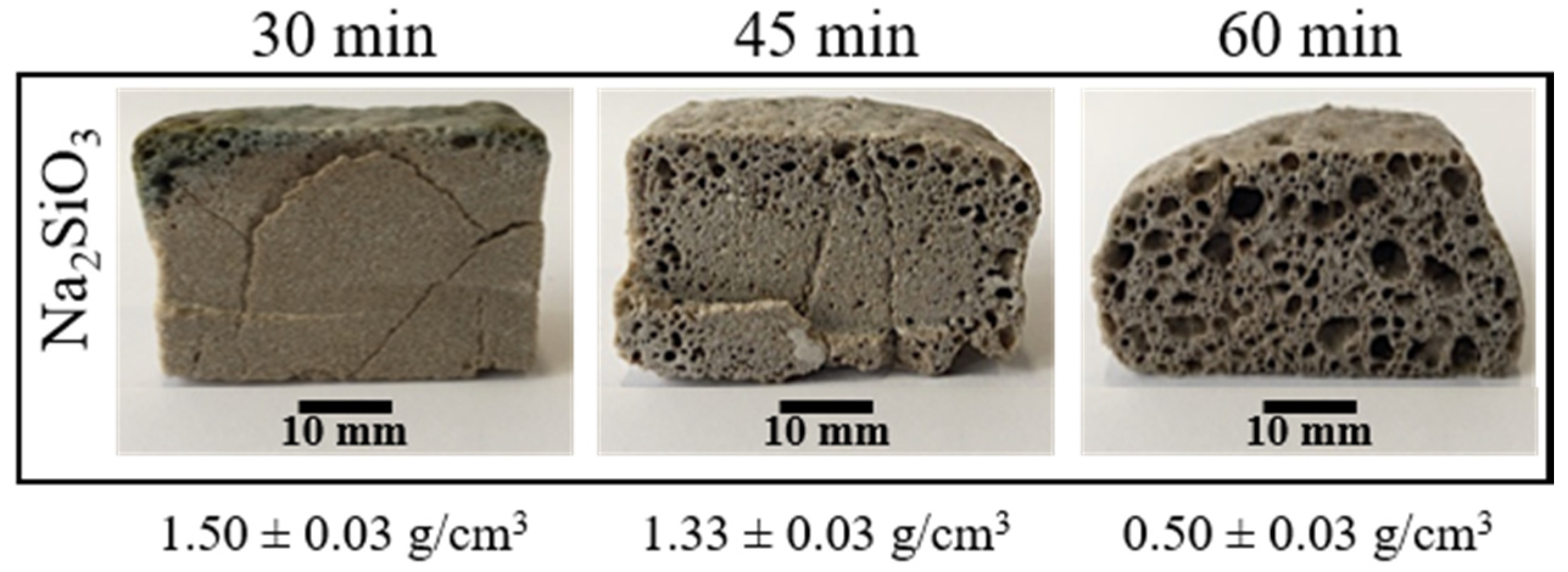
To determine the lowest temperature at which porosity appears, compacted mixtures were sintered and foamed at 750, 800 and 850 °C for 30 min. The internal structure of the obtained materials only presented porosity at 850 °C. However, these porosities do not appear on all the cross-sections, and they were located principally near to the borders of the samples (see Figure 3). To achieve a porosity in all the internal structure, the time of the direct foaming process was varied from 30 to 60 min. Figure 3 shows that an increase in the time allows a porosity on all the cross-sections of the materials obtained. Figure 3 also shows how the apparent density of the materials obtained decreases with an increase in the foaming time. Although an increase in foaming time favors the appearance of porosity, samples with a foaming time of 60 min presented a less symmetric expansion and less homogeneous porosity.
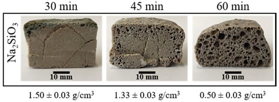
Figure 3.
Internal structure and apparent density of the foamed and sintered materials using sodium silicate (Na2SiO3) as foaming agent (4 t by 3 min). Materials have a composition of 59.2%w SiO2(s), 19%w Na2CO3(s), 5.4%w CaO(s), and 16.4%w Na2SiO3(l).
3.2. Effect of the Pressing Pressure
To see the effect of the pressing pressure on the porosity, the foaming temperature and time were fixed at 850 °C and 45 min, respectively. Figure 4 shows the effect of the pressing pressure on the porosity of the materials obtained. Visually, there is not a clear tendency on the pore formation on the entire internal structure, but it is possible to see that at the lowest pressing pressure (2 t), the sample results are more porous. However, the porosity is non homogenous with bigger pores on the edges. In addition, in the extreme values of the pressing pressure (2, 8 and 10 t), all the samples have pronounced fissures and a non-symmetric expansion. Finally, in the range of 4–6 t, although the samples presented fewer fissures with a better symmetric expansion, pores are only well formed on the edges.

Figure 4.
Internal structure and apparent density of the foamed and sintered materials for 45 min at 850 °C using sodium silicate (Na2SiO3) as foaming agent and varied pressing pressure. Materials have a composition of 59.2%w SiO2(s), 19%w Na2CO3(s), 5.4%w CaO(s), and 16.4%w Na2SiO3(l).
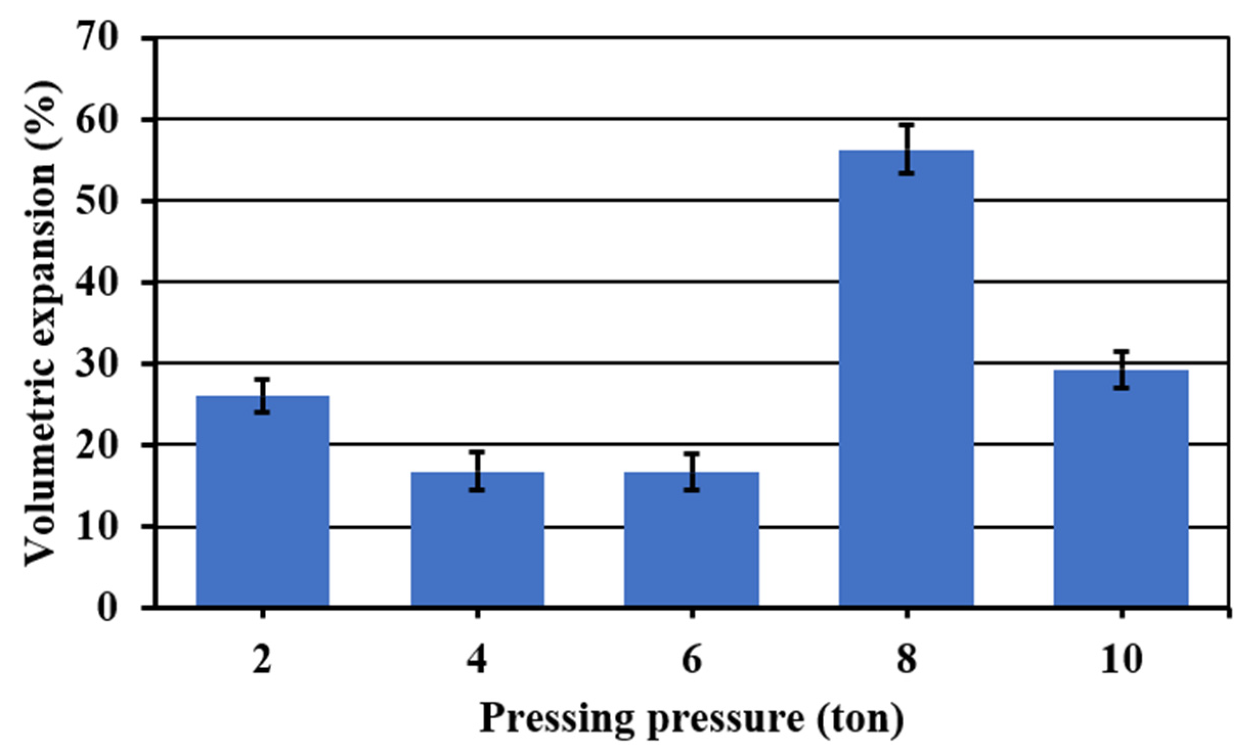
Figure 5 shows the volumetric expansion of the samples as a function of the pressing pressure. Samples in extreme values of the pressing pressure (2, 8 and 10 t) showed the higher volumetric expansions. However, at these pressing pressures, all the samples were irregularly expanded and presented fissures. Acceptable symmetric volumetric expansions without considerable fissures were obtained in a range of pressing pressure of 4–6 t. In this range, a lower apparent density was achieved at 4 t, and given that at this pressure, less wear of the press and a shorter operating time are obtained, for that reason, this one was fixed as the optimum pressing pressure.
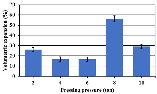
Figure 5.
Volumetric expansion of the foamed and sintered materials for 45 min at 850 °C using sodium silicate (Na2SiO3) as foaming agent and varied pressing pressure. Materials have a composition of 59.2%w SiO2(s), 19%w Na2CO3(s), 5.4%w CaO(s), and 16.4%w Na2SiO3(l).
3.3. Effect of the Powder Mix Composition and Temperature
Table A1 shows the results obtained in the experiments proposed using MODDE®. In total, 26 samples were prepared with varying powder mix composition and foaming temperature. Variables such as apparent density (), porosity (), volumetric expansion (), and pore diameter () were calculated and are shown in the table. In addition, the pore structure of each sample is presented. The ranges obtained for each of the response variables are shown in Table 5.

Table 5.
Characterization chart for foams obtained using sodium silicate as a foaming agent.
From Table A1, by comparing the essays made at 850 °C, it can be observed that samples SS-02 and SS-05, both samples with medium content of sodium silicate (16.4 and 17.0%w, respectively) and higher concentrations of sodium carbonate (19.0%w), presented the lowest apparent density (0.85 ± 0.03 and 0.83 ± 0.03 g/cm3, respectively) and higher volumetric expansion (137.66% ± 3.08% and 124.45% ± 3.08%, respectively). The cell structure of both samples was open, and the pore size was bigger (see Table A1). It has been reported in previous works that Na2CO3 can be used as a foaming agent as well. A big expansion with an asymmetric cell structure can be observed in the obtained results which may be related to the use of Na2CO3 and Na2SiO3. At elevated temperatures, the foaming agent releases gas when it reacts with the glass melt or decomposes due to thermal instability. If the foaming agent is homogenously distributed in the glass powder mixture, the gas formation leads to the expansion and coalescence of many small bubbles with increasing temperature and time [3]. On the other hand, at 870 °C, the samples presented a lower density (0.66–1.19 ± 0.03 g/cm3), higher porosity (56.98%–73.41% ± 2.13%) and high volumetric expansion (22.77%–160.42% ± 3.08%), the SS-19 assay being the sample with the lowest apparent density (0.66 ± 0.03 g/cm3). In addition, at 860 °C, by using medium quantities of quartz (64.75%w), sodium silicate (12.50%w), and sodium carbonate (17.5%w) with high quantities of calcium oxide (5.25%w), a medium pore diameter (0.34–0.53 ± 0.08 mm) and porosity is generated.
These response variables (apparent density (), porosity (), volumetric expansion () and pore diameter () ) and controlled factors (powder mix composition and foaming temperature) were simultaneously calibrated using partial least squares regression through the software MODDE® to observe how the controlling factors affect these response variables directly joined to the porosity formation on the materials. According the results obtained, the variation of the mass fraction of the Na2CO3(s) and CaO(s) in the ranges evaluated did not have a representative impact on the response variables when lower contents of sodium silicate were used. The main factors that modified the porosity were the Na2SiO3(l) mass fraction and the foaming temperature.
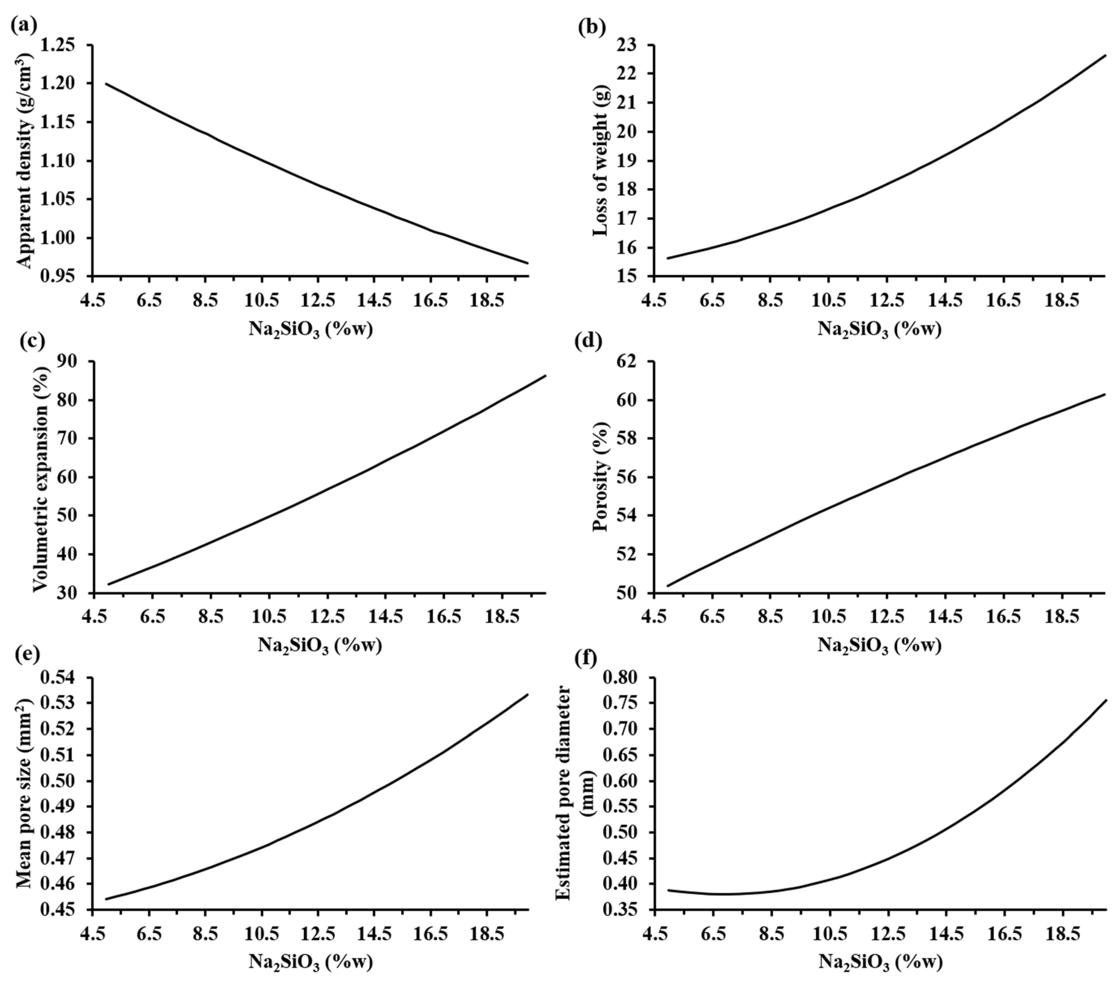
Figure 6 shows the trends of the characterization parameters as a function of the sodium silicate mass fraction according to MODDE® based on the experimental results. It can be observed that, when the sodium silicate content increases, both the loss of weight, volumetric expansion, porosity, mean pore size, and estimated pore diameter increased; meanwhile, the apparent density decreased. Specifically, the apparent density decreased to values lower than 0.95 g/cm3 and the porosity of the samples increased to values higher than 60% when the highest percentage of sodium silicate was employed.
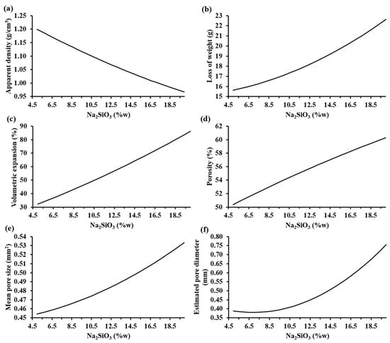
Figure 6.
Trends of the characterization parameters as a function of the sodium silicate mass fraction according to MODDE® based on experimental results: (a) apparent density (SD: ±0.14 g/cm3), (b) loss of weight (SD: ±0.26 g), (c) volume expansion (SD: ±3.08%), (d) porosity (SD: ±2.13%), (e) mean pore size (SD: ±0.04 mm2), and (f) estimated pore diameter (SD: ±0.08 mm) of the foamed materials at 860 °C.
The influence of the increase in the sodium silicate was visible with a bigger pore generation that caused a higher volumetric expansion of the samples, reaching 90% of the initial volume of the compacted mixture. This allowed lightweight materials to be obtained. The estimated pore diameter of the samples increased to values higher than 0.75 mm. Hesky et al. (2015) found that this increment in the pore size is caused by the coalescence of the smaller pores to bigger ones [7]. On the other hand, the loss of weight of the samples was higher than 22% when the highest percentage of sodium silicate was used. This loss of weight is associated to the vaporization of the water from the aqueous solution of sodium silicate and the CO2(g), a product of the partial decomposition of Na2CO3(s) into Na2O(s) and CO2(g) [15].
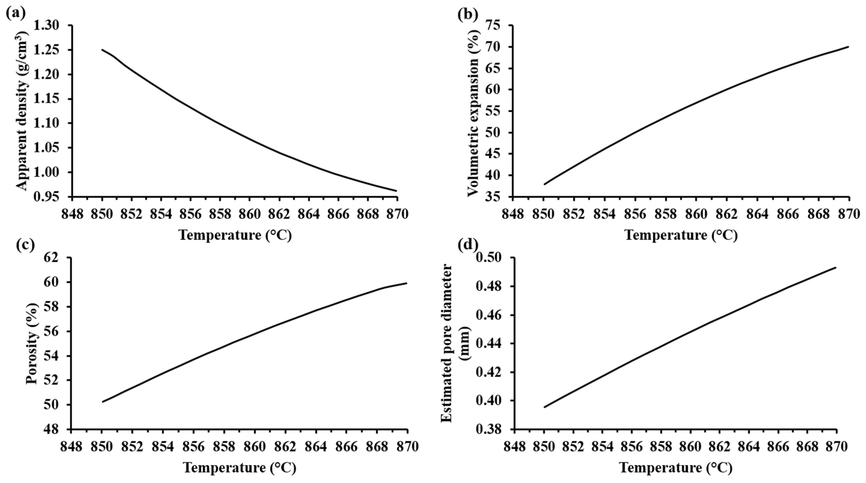
Figure 7a shows that the apparent density of the samples decreased with an increase in the foaming temperature. Accordingly, the volumetric expansion, porosity, and pore diameter of the samples increased when the foaming temperature was increased (see Figure 7b–d). Visibly, the foamed samples at the highest temperature showed the biggest pores (see Table 5). Hesky et al. (2015), found that the cause of these bigger pores is the rapid liberation of the residue water from the hydrated silica molecules at higher temperatures (>800 °C), which generates a greater vapor pressure that provokes a more rapid pore expansion. This dehydration reaction begins at 700 °C [7]. Considering that the softening temperature of the SiO2-CaO-Na2CO3 mixture is around 850–900 °C, the pore formation in the samples is mainly due to the dehydration reaction of the hydrated form of silica. Thermal treatments at 850 °C for 30 min for compacted mixtures of SiO2-CaO-Na2CO3 did not show any appreciable porosity, suggesting that the CO2(g) produced by the decomposition of Na2CO3(s) is not responsible for the porosity of the foam samples. According to Kim and Lee (2001), the thermal decomposition of pure Na2CO3(s) (with a melting point at 850 °C) is too slow, and appreciable loss of mass product of the volatilization begins at 900 °C [15].
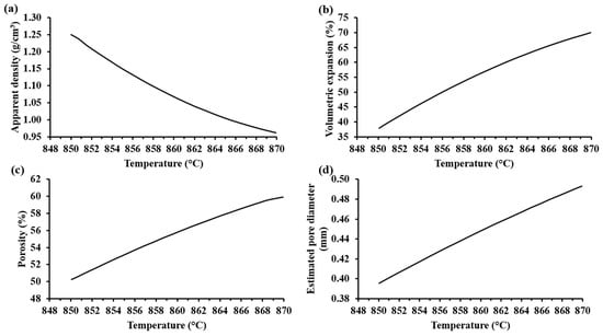
Figure 7.
Trends of the characterization parameters as a function of the foaming temperature according to MODDE® based on experimental results: (a) apparent density (SD: ± 0.003 g/cm3), (b) volume expansion (SD: ± 23.04%), (c) porosity (SD: ± 0.04%), and (d) estimated pore diameter (SD: ± 0.27 mm) of the foamed materials with 20%w Na2SiO3(l).
Through the optimizer tool of the software MODDE®, it was established that a mixture composition of 59.83%w SiO2(s), 16%w Na2CO3(s), 5.1%w CaO(s), and 19.99%w Na2SiO3(l) and a temperature of 859 °C are the optimum controlled factors to obtain a foamed material with the minimum apparent density and maximum porosity possible. The samples elaborated at these conditions presented an apparent density of 1.09 ± 0.03 g/cm3 and a porosity of 56.01% ± 1.12%. The mechanical strength for these samples was measured in a CBR loading press at a loading rate of ¼ inches per 30 s, resulting in 3.90 ± 0.16 MPa.
The properties and, consequently, the possible applications of the cellular solids are a function of their cellular structure and porosity. As can be seen in Figure 8, some samples are mainly open-cell foams with a very wide distribution of the cell sizes, where the smaller cells make up the cell walls of the larger cells, giving a hierarchical cellular material with cells at several levels of scales [16]. Quartz is covalently bonded, giving the obtained ceramic foams higher melting points and moduli than other types of materials (e.g., polymer foams). These covalent bonds give strong elastic coupling between atoms too, which results in larger thermal conductivities [16]. However, the thermal conductivity of the porous materials is a function of the porosity, the diameter of the pores, and the kind of pores (open or closed) [17]. Glass and ceramics foams such as those obtained in this work become attractive as insulation materials due to their higher melting points [6,18]. Taking this into account, the process proposed in this work allows solid foams to be obtained with high melting points and with porosities and type of pores that produce materials that could find application as insulation materials. These kind of silica foams find application in the filtration of liquid metals and for gas and liquid phase catalysis at elevated temperatures due to their high melting points [16].

Figure 8.
The cellular structure of the solid foam obtained using sodium silicate as a foaming agent. Material with a composition of 59.2%w SiO2(s), 16%w Na2CO3(s), 5.7%w CaO(s), and 19.1%w Na2SiO3(l).
Commonly, an industrial glass foam insulation panel has a closed cellular structure with a mean pore diameter of 1.5 mm, average porosities of 80% and apparent densities <0.30 g/cm3 [1,19]. The production process of these glass-ceramic panels is through the mixing of glass powder with foaming agents usually from carbonaceous sources [16,17]. The focus of recent investigations on the development of glass-ceramic foams is the use of alternative raw material sources, such as waste-glass, flay ash, tailings, and other recycled industrial wastes [14]. The glass-ceramic foams obtained from these raw material sources present a wide range of characteristic properties. According to the literature, foams prepared using different proportions of waste-glass and other several components present mean cell dimensions of 0.25–2.00 mm, porosities of 60%–86%, and apparent densities of 0.13–0.8 g/cm3 [5,6,19,20,21]. Foams prepared using different proportions of fly ash and several other components present mean cell dimensions of 0.2–3 mm, porosities of 35%–78%, and apparent densities of 0.14–1.37 g/cm3 [22,23,24,25,26]. Foams prepared using different proportions of tailings and several other components present mean cell dimensions of 0.2–4.0 mm, porosities of 35%–84%, and apparent densities of 0.19–1.37 g/cm3 [8,9,10,24,25,26,27]. According to Table A1, the foams obtained in this work have characteristic properties within the ranges of the foams made with these alternative sources. However, the use of only quartz as a source of SiO2 brings the opportunity to use an alternative cheap source of silica that can be extracted from waste sources such as mine tailings. On the other hand, the use of sodium silicate as a foaming agent allows a powder foaming process without the emission of pollutants gases (e.g., CO2) harmful to the environment. The direct foaming process proposed in this work allows the production of silica foams at relatively lower temperatures and without the use of melting pots, which could be translated into cost reductions due to lower energy consumption, expenses in melting pots, and loss of foamed material.
4. Conclusions
The present study reveals that a direct foaming process of mixtures without melting pots of commercial quartz with CaO and Na2CO3 as fluxing agents and Na2SiO3·5H2O as a foaming agent allows the production of foams with different characteristics that could find applications as construction material and filter and catalysis material at high temperatures. The study of the minimum values of the temperature and time of the foaming process showed that foams with symmetric expansions and without fissures can be produced from a temperature of 850 °C, a minimum foaming time of 45 min, and a pressing pressure in a range of 4–6 t. The multilevel quadratic design realized with statistical software (MODDE®) showed that the foaming of the samples is principally affected by the temperature and the content of the sodium silicate. Their apparent density decreased with an increase in the concentration of Na2SiO3(l) and foaming temperature, and their porosity increased with an increase in the concentration of Na2SiO3(l) and foaming temperature. The samples obtained at the optimum controlled factors (59.83%w SiO2(s), 16%w Na2CO3(s), 5.1%w CaO(s), 19.99%w Na2SiO3(l) and a temperature of 859 °C for 45 min) showed an apparent density, porosity, and mechanical strength of 1.09 ± 0.03 g/cm3, 56.01% ± 1.12%, and 3.90 ± 0.16 MPa, respectively. Glass and ceramic foams such as those obtained in this work become attractive as insulation materials that could find applications where high temperatures occur due to their higher melting points. For instance, Hesky et al. [7] commented that thermal conductivity of porous materials depends on the heat transfer by conduction through the solid and gaseous phase and radiation. With decreasing the solid content of a material, porosity increases and the thermal conductivity decreases. In addition, with pore sizes higher than 5 mm, convection may occur and the thermal conductivity increases [28]. For the samples analyzed in our manuscript, the smallest pore dimension was 0.11 mm, and the largest pore dimension was 10.13 mm. Therefore, it is possible to assume that the samples with pores of a dimension lower than 5 mm could be used as insulation materials.
These kind of silica foams could find application in the filtration of liquid metals and for gas and liquid phase catalysis at elevated temperatures. Future research can be related to the use of SiO2 from alternative sources, such as tailings and other recycled wastes from mining in the preparation of ceramic foams.
Author Contributions
Conceptualization, methodology, software, validation, formal analysis, investigation, writing – original draft preparation, writing – review and editing and supervision, L.U. and J.D.G.; data curation, visualization and investigation, A.V.; project administration, funding acquisition and resources validation, L.U. All authors have read and agreed to the published version of the manuscript.
Funding
This study was realized with funds granted by the project FIC-R 40008910-0, funds for Competitiveness of the Regional Government of O’Higgins.
Acknowledgments
The researchers acknowledge to Cristina Cereceda for her technical support.
Conflicts of Interest
The authors declare no conflicts of interest.
Appendix A

Table A1.
Results of characterization and pore structures of the foamed and sintered materials for 45 min using sodium silicate (Na2SiO3) as a foaming agent, varying the temperature and the mixture composition according the essay proposed using MODDE®.
Table A1.
Results of characterization and pore structures of the foamed and sintered materials for 45 min using sodium silicate (Na2SiO3) as a foaming agent, varying the temperature and the mixture composition according the essay proposed using MODDE®.
| Sample | T (°C) | SiO2 (%w) | Na2SiO3 (%w) | CaO (%w) | Na2CO3 (% w) | (%) | Pore Structures | |||
|---|---|---|---|---|---|---|---|---|---|---|
| SS-01 | 850 | 59.20 | 19.10 | 5.70 | 16.0 | 1.18 | 54.20 | 10.74 | 0.38 |  |
| SS-02 | 59.20 | 17.00 | 4.80 | 19.0 | 0.85 | 66.30 | 137.66 | 1.58 |  | |
| SS-03 | 70.30 | 5.90 | 4.80 | 19.0 | 1.22 | 51.97 | 19.09 | 0.64 |  | |
| SS-04 | 59.20 | 19.00 | 4.80 | 17.0 | 0.95 | 62.38 | 102.50 | 1.13 |  | |
| SS-05 | 59.20 | 16.40 | 5.40 | 19.0 | 0.83 | 68.01 | 124.45 | 0.95 |  | |
| SS-06 | 70.30 | 6.00 | 5.70 | 18.0 | 1.73 | 32.70 | −10.81 | 0.21 |  | |
| SS-07 | 70.30 | 8.60 | 5.10 | 16.0 | 1.54 | 40.00 | −8.57 | 0.18 |  | |
| SS-08 | 70.30 | 8.30 | 5.40 | 16.0 | 1.37 | 46.69 | −5.71 | 0.27 |  | |
| SS-09 | 62.90 | 16.30 | 4.80 | 16.0 | 0.95 | 61.44 | 56.62 | 0.48 |  | |
| SS-10 | 66.60 | 8.70 | 5.70 | 19.0 | 1.43 | 43.04 | 12.88 | 0.29 |  | |
| SS-11 | 870 | 59.20 | 20.00 | 4.80 | 16.0 | 0.80 | 68.38 | 160.42 | 1.39 |  |
| SS-12 | 70.30 | 5.00 | 5.70 | 19.0 | 1.10 | 56.98 | 30.07 | 0.42 |  | |
| SS-13 | 70.30 | 8.90 | 4.80 | 16.0 | 1.19 | 53.01 | 22.77 | 0.37 |  | |
| SS-14 | 59.20 | 17.00 | 4.80 | 19.0 | 0.85 | 66.24 | 105.08 | 1.20 |  | |
| SS-15 | 59.20 | 16.10 | 5.70 | 19.0 | 0.77 | 70.08 | 79.30 | 0.69 |  | |
| SS-16 | 70.30 | 6.90 | 4.80 | 18.0 | 0.92 | 63.87 | 62.85 | 1.13 |  | |
| SS-17 | 70.30 | 7.00 | 5.70 | 17.0 | 1.07 | 57.27 | 25.89 | 0.39 |  | |
| SS-18 | 70.30 | 5.60 | 5.10 | 19.0 | 0.94 | 62.86 | 70.27 | 0.55 |  | |
| SS-19 | 62.90 | 13.30 | 4.80 | 19.0 | 0.66 | 73.41 | 134.38 | 0.56 |  | |
| SS-20 | 62.90 | 15.40 | 5.70 | 16.0 | 0.81 | 67.99 | 100.89 | 0.43 |  | |
| SS-21 | 66.60 | 11.70 | 5.70 | 16.0 | 1.00 | 60.64 | 40.63 | 0.29 |  | |
| SS-22 | 59.20 | 18.05 | 5.25 | 17.5 | 0.79 | 69.22 | 126.85 | 1.12 |  | |
| SS-23 | 860 | 64.75 | 12.50 | 5.25 | 17.5 | 1.20 | 52.66 | 42.05 | 0.40 |  |
| SS-24 | 64.75 | 12.50 | 5.25 | 17.5 | 0.95 | 52.17 | 35.51 | 0.53 |  | |
| SS-25 | 64.75 | 12.50 | 5.25 | 17.5 | 1.19 | 52.94 | 42.05 | 0.34 |  | |
| SS-26 | 64.75 | 12.50 | 5.25 | 17.5 | 1.26 | 50.91 | 39.87 | 0.42 |  |
References
- Scheffer, M.; Colombo, P. Cellular Ceramics: Structure, Manufacturing, Properties and Applications; Wiley-VCH Verlag GmbH & Co. KGaA: Weinheim, Germany, 2005. [Google Scholar]
- Studart, A.R.; Gonzenbach, U.T.; Tervoort, E.; Gauckler, L.J. Processing routes to macroporous ceramics: A review. J. Am. Ceram. Soc. 2006, 89, 1771–1789. [Google Scholar] [CrossRef]
- Petersen, R.R.; König, J.; Smedskjaer, M.M.; Yue, Y. Effect of Na2CO3 as foaming agent on dynamics and structure of foam glass melts. J. Non. Cryst. Solids. 2014, 400, 1–5. [Google Scholar] [CrossRef]
- Zhou, M.; Ge, X.; Wang, H.; Chen, L.; Chen, X. Effect of the CaO content and decomposition of calcium-containing minerals on properties and microstructure of ceramic foams from fly ash. Ceram. Int. 2017, 43, 9451–9457. [Google Scholar] [CrossRef]
- Da Silva, R.C.; Kubaski, E.T.; Tenório-Neto, E.T.; Lima-Tenório, M.K.; Tebcherani, S.M. Foam glass using sodium hydroxide as foaming agent: Study on the reaction mechanism in soda-lime glass matrix. J. Non. Cryst. Solids. 2019, 511, 177–182. [Google Scholar] [CrossRef]
- König, J.; Petersen, R.R.; Yue, Y. Fabrication of highly insulating foam glass made from CRT panel glass. Ceram. Int. 2015, 41, 9793–9800. [Google Scholar] [CrossRef]
- Hesky, D.; Aneziris, C.G.; Groß, U.; Horn, A. Water and waterglass mixtures for foam glass production. Ceram. Int. 2015, 41, 12604–12613. [Google Scholar] [CrossRef]
- Xi, C.; Zheng, F.; Xu, J.; Yang, W.; Peng, Y.; Li, Y.; Li, P.; Zhen, Q.; Bashir, S.; Liu, J.L. Preparation of glass-ceramic foams using extracted titanium tailing and glass waste as raw materials. Constr. Build. Mater. 2018, 190, 896–909. [Google Scholar] [CrossRef]
- Zhang, Q.; He, F.; Shu, H.; Qiao, Y.; Mei, S.; Jin, M.; Xie, J. Preparation of high strength glass ceramic foams from waste cathode ray tube and germanium tailings. Constr. Build. Mater. 2016, 111, 105–110. [Google Scholar] [CrossRef]
- Kazmina, O.V.; Tokareva, A.Y.; Vereshchagin, V.I. Using quartzofeldspathic waste to obtain foamed glass material. Resour. Technol. 2016, 2, 23–29. [Google Scholar] [CrossRef]
- Ahmad, S.; Latif, M.A.; Taib, H.; Ismail, A.F. Short review: Ceramic foam fabrication techniques for wastewater treatment application. Adv. Mater. Res. 2013, 795, 5–8. [Google Scholar] [CrossRef]
- Aasly, K. Properties and Behavior of Quartz for the Silicon Process. Ph.D. Thesis, Norwegian University of Science and Technology, Trondheim, Norway, 2008. [Google Scholar]
- Karandashova, N.S.; Goltsman, B.M.; Yatsenko, E.A. Analysis of influence of foaming mixture components on structure and properties of foam glass. IOP Conf. Ser. Mater. Sci. Eng. 2017, 262. [Google Scholar] [CrossRef]
- Li, Z.; Luo, Z.; Li, X.; Liu, T.; Guan, L.; Wu, T.; Lu, A. Preparation and characterization of glass–ceramic foams with waste quartz sand and coal gangue in different proportions. J. Porous Mater. 2016, 23, 231–238. [Google Scholar] [CrossRef]
- Kim, J.W.; Lee, H.G. Thermal and carbothermic decomposition of Na 2 CO 3 and Li 2 CO 3, Metall. Mater. Trans. B 2001, 32, 17–24. [Google Scholar] [CrossRef]
- Gibson, L.J.; Ashby, M.F. Cellular Solids Structure and Properties; Cambridge University Press: Cambridge, UK, 1999; Available online: https://books.google.pt/books/about/Cellular_Solids.html?id=IySUr5sn4N8C&source=kp_cover&redir_esc=y (accessed on 7 January 2020).
- Rice, R.W. Porosity of Ceramics; CRC Press: New York, NY, USA, 1998. [Google Scholar]
- D’Amore, G.K.O.; Caniato, M.; Travan, A.; Turco, G.; Marsich, L.; Ferluga, A.; Schmid, C. Innovative thermal and acoustic insulation foam from recycled waste glass powder. J. Clean. Prod. 2017, 165, 1306–1315. [Google Scholar] [CrossRef]
- Lakov, L.; Toncheva, K.; Staneva, A.; Simeonova, T.; Ilcheva, Z. Composition, synthesis and properties of insulation foam glass obtained from packing glass waste. J. Chem. Technol. Metall. 2013, 48, 125–129. [Google Scholar]
- König, J.; Petersen, R.R.; Yue, Y. Influence of the glass particle size on the foaming process and physical characteristics of foam glasses. J. Non. Cryst. Solids. 2016, 447, 190–197. [Google Scholar] [CrossRef]
- Ducman, V.; Kovačević, M. The foaming of waste glass. Key Eng. Mater. 1997, 132–136, 2264–2267. [Google Scholar] [CrossRef]
- Hojaji, H. Development of foam glass structural insulation derived from fly ash. MRS Proc. 1988, 136, 185–206. [Google Scholar] [CrossRef]
- Chen, X.; Lu, A.; Qu, G. Preparation and characterization of foam ceramics from red mud and fly ash using sodium silicate as foaming agent. Ceram. Int. 2013, 39, 1923–1929. [Google Scholar] [CrossRef]
- Liu, T.; Lin, C.; Liu, J.; Han, L.; Gui, H.; Li, C.; Zhou, X.; Tang, H.; Yang, Q.; Lu, A. Phase evolution, pore morphology and microstructure of glass ceramic foams derived from tailings wastes. Ceram. Int. 2018, 44, 14393–14400. [Google Scholar] [CrossRef]
- Liu, T.; Tang, Y.; Han, L.; Song, J.; Luo, Z.; Lu, A. Recycling of harmful waste lead-zinc mine tailings and fly ash for preparation of inorganic porous ceramics. Ceram. Int. 2017, 43, 4910–4918. [Google Scholar] [CrossRef]
- Liu, T.; Tang, Y.; Li, Z.; Wu, T.; Lu, A. Red mud and fly ash incorporation for lightweight foamed ceramics using lead-zinc mine tailings as foaming agent. Mater. Lett. 2016, 183, 362–364. [Google Scholar] [CrossRef]
- Yin, H.; Ma, M.; Bai, J.; Li, Y.; Zhang, S.; Wang, F. Fabrication of foam glass from iron tailings. Mater. Lett. 2016, 185, 511–513. [Google Scholar] [CrossRef]
- Wang, Y. Performance-Based Fire Engineering of Structures; CRC Press: Boca Raton, FL, USA, 2012. [Google Scholar]
© 2020 by the authors. Licensee MDPI, Basel, Switzerland. This article is an open access article distributed under the terms and conditions of the Creative Commons Attribution (CC BY) license (http://creativecommons.org/licenses/by/4.0/).

