1. Introduction
Externally bonded fiber-reinforced polymer (FRP) sheets or plates have become popular for strengthening reinforced concrete structures in recent decades. The effectiveness of this technique relies on the integrity of the bond between the FRP sheet/plate and concrete [
1,
2]. Hitherto, numerous studies were conducted to investigate the short-term behavior of the FRP-to-concrete bond, both numerically and experimentally [
3,
4,
5,
6]. The harsh service environment of sustained loading, elevated service temperature (EST), and their combination deteriorates the FRP-to-concrete bond [
7,
8,
9,
10,
11,
12]. EST denotes the elevation of the matrix material and the bonding adhesive slightly above the glass transition temperature (
Tg) [
13]. FRP composites exhibit a poor resistance to EST because organic polymers are used as the matrix materials. Above the
Tg, the elastic modulus of the matrix materials significantly drops and the material changes from a hard, glass-like material to a more rubber-like material [
14]. The bonding adhesive softens quickly around the
Tg and the sustained loading may deteriorate the bond between the adhesive layer and concrete. Studies of the influences of temperature variation, sustained loading, and the combination of both on the FRP-to-concrete bond are scarce. Therefore, although the externally bonded FRP technique is well established, it is essential for designers to understand how the FRP-to-concrete interface behaves under variable temperature conditions and sustained loading.
The temperature variation influences the epoxy and the FRP-to-concrete interfacial bond significantly. Leone et al. investigated the effects of temperature at 20, 50, 65, and 80 °C on the CFRP (carbon FRP)/GFRP (glass FRP) sheet-to-concrete by using a double-lap shear test [
8]. The
Tg of the epoxy resin is 55 °C. The ultimate load capacity of CFRP sheet-to-concrete increased in the temperature range from 20 to 50 °C (i.e., below
Tg). Compared to the case of 20 °C, 50 °C increased the ultimate load capacity by 24%. However, at 80 °C, which is above the
Tg, the ultimate load capacity was reduced by 10%. Ferrier et al. adopted double-lap shear tests to investigate the bond performance of CFRP sheet/plate-concrete exposed to temperatures in the range of −40 to 120 °C [
15]. In the case of
Tg = 76 °C for the epoxy resin, the EST at 80 °C reduced the ultimate load capacity by 70% for the CFRP sheet-concrete. In the case of
Tg = 90 °C for the epoxy adhesive, the EST at 100 °C reduced the ultimate load capacity by 31% for the CFRP plate-concrete. Adelzadeh investigated the CFRP plate-concrete at room temperature, 60, 80, 105, 150, and 200 °C by a single-lap shear test [
16]. The
Tg of the epoxy adhesive (Sikadur30) is 60 °C. A 50% loss of strength for CFRP plate-concrete bonds was observed at a temperature 40 °C above the
Tg of the adhesive. The reduction in the mechanical properties of the adhesive at EST is important for the strengthened structures, primarily in relation to the bond performance. The transformation in the failure mode from concrete cohesive failure to adhesive-concrete interfacial debonding failure causes the degradation of the ultimate load capacity. Dai et al. developed a theoretical nonlinear local bond-slip model for FRP laminates externally bonded to concrete at elevated temperature [
9]. The prediction showed that the ultimate load capacity reduced to zero when the temperature in the adhesive layer was twice that of
Tg (°C). This leads to the deterioration of the physical bonding between epoxy and concrete, which is formed by strong hydrogen bonds between the epoxy and SiO2 (concrete), involving highly polar aliphatic hydroxyl and ether groups in epoxy adhesive chains [
17]. The service temperature proximity to
Tg results in an increased rate of physical aging, which in turn results in the evolution of material properties. Furthermore, service temperature denotes one below the
Tg of the matrix material and the bonding adhesive. Physical aging at the service temperature was identified as the reason for the increase in
Tg of the resin [
18]. Temperatures close to and above the
Tg the of adhesive reduced elastic modulus of the adhesive [
19].
Sustained loading significantly influences the bond strength of FRP-to-concrete. Jeong et al. investigated the effects of curing time, service temperature, and sustained loading duration on the mechanical behavior of CFRP sheet/concrete-bonded connections by using a single-lap shear test [
11]. The sustained loading increases the ultimate load capacity of CFRP sheet-to-concrete by 23% after 31 days at 23 °C. The positive effects of sustained loading on the interfacial bond decreases with duration, and level of sustained loading. Jia et al. investigated the effects of the indoor laboratory, outdoor, elevated temperature/dry, and freeze/thaw on glass sheet-concrete bonds with sustained loads through a three-point flexure test [
20]. Twenty-five percent of the calculated nominal ultimate moment in ambient indoor temperature did not vary the bond strength of the glass fiber reinforced-polymer-concrete-bonded interfaces. Because of the different creep characteristics of the constituent materials, the duration time, and sustained loading may induce stress concentration at the interface and influence the stress transferred to the FRP. Zhou et al. investigated the coupling of the sustained load and moisture conditions on the concrete-epoxy interface bond [
21]. A sandwiched concrete–epoxy beam was adopted and applied to a three-point bending test. The results of the three-point bending test show that the sustained loading with 30% of
Fu decreases the interfacial fracture energy of concrete-epoxy interface by 41% after four weeks. Sustained loading increases the effective bond length. A pre-stressed FRP sheet bonded to a beam and a double lap shear test was conducted [
22]. The pre-stress level was 20%–82% of the failure load. A 70–80 mm relaxation zone in the double-lap shear test was reported after 4.3 days, at 50% of the initial ultimate load capacity in the double-lap shear test. The effective bond length continued to increase with the duration of sustained loading in terms of the strengthening concrete beam with pre-stressed FRP sheets.
The above review clearly illustrates that both sustained loading and temperature variation are critical in the bond performance. At the service temperature (below
Tg), the temperature effects are insignificant in specimens subjected to sustained load [
11]. The combined effect of the temperature and mechanical loads becomes important for large differences in the coefficient of thermal expansion with the increase in the temperature [
12]. However, relatively few studies have been conducted on the FRP-concrete interface at variable temperatures under service loads. Hence, in this study, the combined effects of temperature variation and sustained loading on the interface behavior of FRP-concrete were investigated, together with the interfacial fracture energy, bond stress–slip relationship, and effective bond length. A two-stage prediction equation of fracture energy is proposed considering the coupled effects of temperature variation and sustained loading. Basalt fiber has better mechanical properties than E-glass fiber, and is more widely available and cheaper than carbon fiber. Basalt FRP is believed to be a good alternative in civil engineering; therefore, BFRP sheets were bonded to concrete blocks in order to study the bond behavior of the BFRP sheet-to-concrete system.
3. Results and Discussion
3.1. Failure Mode of BFRP–Concrete Bond
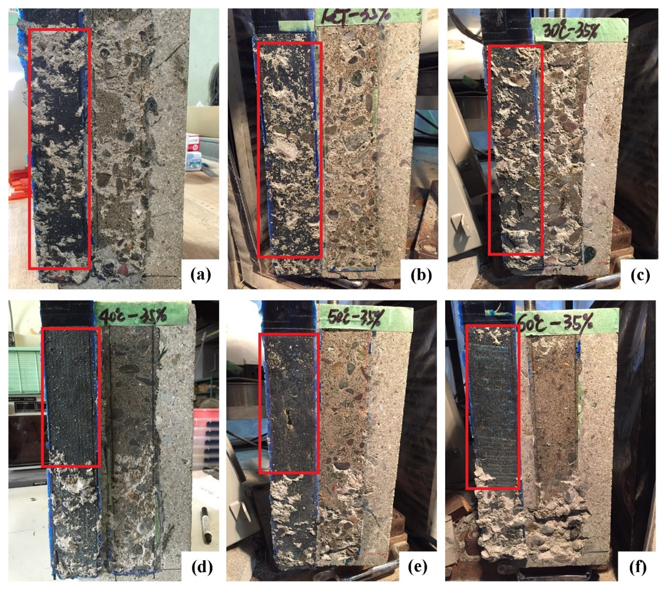
Figure 3 shows the typical failure modes for the test specimens, which exhibit different patterns after exposure at variable temperatures and pre-sustained loading conditions. The failure mode of the control specimen was primarily cohesion failure at the thin concrete layer (
Figure 3a); this is the typical failure mode for the FRP-concrete shear pull-off test [
15]. For the specimens tested at 15 and 30 °C with pre-sustained loading (
Figure 3b,c), the failure mode is the same as that of the control specimen implying that the failure modes below 40 °C are controlled by concrete tensile strength. It was reported that the pre-sustained load with 23 °C may increase the failure area of the interfacial debonding [
11]. That phenomenon is different from the present results below 40 °C and is attributed to the duration of the pre-sustained load (251 days) in [
11]. Compared to the present duration of pre-sustained loading, longer durations accumulate the damage at the interface between adhesive layer and the concrete.
In the case of an environment temperature at 40 °C or higher, the failure mode changes from concrete failure to adhesion failure at the adhesive-to-concrete interface.
Figure 3d–f shows that the complete debonding between the adhesive layer and concrete occurs for the specimens from 40 to 60 °C.
Tg in the adhesive layer dominates the failure modes above 40 °C in the present cases. The environment temperature between 40 and 60 °C deteriorates the primer–concrete interfacial bond. It was reported that the temperature above
Tg changes the failure mode from concrete cohesive failure to interfacial debonding [
15,
33]. The adhesion between adhesive layer and concrete has higher resistance than that of concrete to instantaneous loading [
23], which indicates that the failure evolution depends on the temperature rather than the pre-sustained load within a short duration (e.g., 3 h).
The previous studies were reported that the weakest region occurs at the surface of the concrete substrate at the temperature below
Tg [
8,
15,
34]. The fracture energy of the failure in concrete is smaller than that of the failure at the primer–concrete interface. It was reported that the value of interfacial fracture energy was approximately 0.04 N/mm for the concrete, while the interfacial fracture energy between FRP and concrete is more than 3 N/mm [
35]. In the case of EST, the change of the failure mode occurs when the temperature exceeds the
Tg. This indicates that the fracture energy of the interfacial bond between primer and concrete rapidly decreases when the temperature is above
Tg. However, in the present case at 40 °C, which is below the
Tg, the failure mode has shifted from concrete cohesive failure to adhesive layer-concrete debonding. Ferrier et al. results were reported that at 60 °C without a pre-sustained load, the failure mode of the CFRP sheet-concrete with
Tg = 76 °C also shifted to interfacial debonding [
12]. This indicates that a temperature close to
Tg may shift the failure mode from concrete cohesive failure to interfacial debonding. It is difficult to distinguish the effect of the pre-sustained loading with 35% of failure load on the change of failure mode at 40 °C in present study. The effects of pre-sustained load on the failure mode at temperatures close to
Tg should be further investigated.
3.2. Load-Slip of BFRP–Concrete Bond
Figure 4 shows the comparisons of strain–slip curves. “Exp.-X°C-35%” represents the strain read by the strain gauge on the FRP. “Exp. Results determined by load” indicates the strain determined by load. “Ana.-X°C-35%” is determined according to Dai et al. equation [
29]. The strain–slip curve of “Exp.-X°C-35%” matches that of “Exp. Results determined by load” in
Figure 4.
Dai et al.’s equation was adopted to evaluate the BFRP-to-concrete bond performance. The interfacial bond stress (
τ) is expressed as follows [
29]:
where
τ is a function of slip
s.
During the pull-out test, the pull-out forces, strain of BFRP, and the slip at the loaded end can be measured accurately through a load cell, strain gauge, and displacement transducer. As a result, the relationship between the strains of BFRP sheets and the slips at the loaded end, in other words, the function of f(s), can be obtained directly from simple pull-out tests.
Strain is assumed to be related to slip:
where
A and
B can be fitted by the
ε-s curve of the experimental results. In fact,
A is the maximum strain in the FRP with a sufficiently long bond length.
B is regarded as the stiffness index that controls the shape of the bond-slip curve [
36].
A and
B for all the specimens were obtained by fitting Equation 3 and are listed in
Table 1.
The ultimate load capacity is determined by the maximum strain at the loaded end as follows:
where
bf is the width of the BFRP. It is worth noting that
εmax is equal to
A. The evolution of the elastic modulus of the BFRP sheet at temperatures from 30 to 60 °C were determined by the modified Bisby’s model [
9,
37].
Pu values for all specimens are listed in
Table 1.
Figure 4 shows the typical measured strain–slip data and the corresponding regressed fitting curve at 15, 40, and 60 °C. In comparisons of CT15 and T15, the pre-sustained load increased
A and
B by 1.4% and 13%, respectively. Compared to the cases at 15 °C with pre-sustained loading, the values of
A at 30 and 40 °C increase by 20% and 9%, respectively. The temperature below
Tg enhances the hydrogen bonds between the epoxy and SiO
2 (contained in concrete). The value of
B for both at 15 and 30 °C are similar. Compared to the specimens at 15 °C, the temperature of 40 °C reduces the value of
B by 58%, which is attributed to the deterioration of the primer–concrete interfacial bond.
Compared to the specimens at 15 °C, the EST of 50 and 60 °C reduces the values of A by 38% and 44%, respectively, due to the deterioration of the primer–concrete bond. The value of A is controlled by the primer–concrete interfacial bond, which decreases with temperature. Compared to the specimens at 15 °C, the values of B at 50 and 60 °C decrease by 73% and 82%, respectively, attributed to the softening of the bonding adhesive, and the disruption of bonds between the primer and concrete.
3.3. Shear Bond Strength and Fracture Energy
According to references [
29], the bond stress–slip relationship and fracture energy can be expressed as:
The fracture energy is determined by Equation 6 and listed in
Table 1.
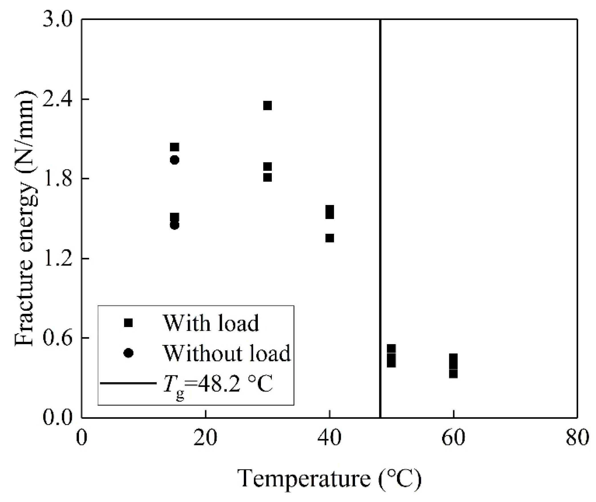
Figure 5 shows an insignificant effect of pre-sustained loading on the fracture energy at 15 °C. Compared to the case at 15 °C, the fracture energy at 30 °C increases by 46%. The temperature results in post-curing and stronger bonds between the primer and concrete.
Compared to the cases at 15 °C, the fracture energy at 40 °C only increases by 11%, which is lower than that at 30 °C. It is worth noting that the trends of fracture energy at 40 °C are different from those of the values of
A and
B. It was reported that the environment temperature below
Tg influences the fracture energy insignificantly [
38]. The pre-sustained loading at 40 °C accelerates the debonding between the primer and concrete. Meanwhile, a temperature of 40 °C enhances the crosslinking of the epoxy and primer-SiO
2 interfacial bond, thus resulting in a higher value of
A and a lower value of
B at 40 °C.
The fracture energy decreases rapidly when the temperature at the surface of BFRP reaches 50 °C, which is above
Tg. Compared to the specimens at 15 °C, the fracture energies at 50 and 60 °C reduce by 73% and 77%, respectively. The mobility of the chain in the epoxy increases with EST. The epoxy is rather soft and exhibits a large deformation above 50 °C, which reduces the shear stiffness of the bond layer involved in a combined layer of primer and adhesive. It is reported that the fracture energy increases with the decreasing shear stiffness of the bond layer [
29]. In fact, the fracture energies of the specimens at both 50 and 60 °C are smaller than that at 15 °C. It is indicated that the pre-sustained loading and EST significantly deteriorates the bond between the primer and concrete.
The bond stress–slip relationship determined by Equation 5 is plotted in
Figure 6. According to Ref. [
29], the maximum shear bond stress and the corresponding slip can be expressed as:
At 15 °C, the pre-sustained load increases the shear bond stress by 18.6%. As discussed above, the pre-sustained load increases B by 13%. According to Equation 8, the increase in the shear bond stress appears to result from the increase in B.
The shear bond stress increases with increasing environment temperature from 15 to 30 °C. This is attributed to the stronger interfacial bond owing to the post-curing. The shear bond stress decreases with the environment temperature above 40 °C, while the corresponding slip increases. The corresponding slip decreases owing to the decrease in B. The rapid decrease in the shear bond stress at 40 °C is attributed primarily to the shift in failure mode from concrete cohesive failure to interface debonding.
The maximum shear bond stress of the CFRP sheet-concrete with
Tg =76 °C of adhesive epoxy increased by 18% at temperature from 20 to 40 °C [
12]. In the present study, the maximum shear bond stress increased 23% at the temperature from 15 to 30 °C. The trends of maximum shear bond stress with temperature are similar for both the present study and the CFRP sheet-concrete in [
12]. The difference in the increase between 18% and 23% is insignificant.
After 153 days of pre-sustained loading at 45% of the failure load the maximum shear bond stress of CFRP sheet-concrete increased by 65% [
11]. It can be concluded that the maximum shear bond stress of the CFRP sheet-concrete increased with temperatures. The pre-sustained load below 45% of the failure load has positive effects on the maximum shear bond stress of CFRP sheet-concrete, and it results in the increase of the maximum shear bond stress with loading duration.
The temperature of 60 and 80 °C reduced the maximum shear bond stress of the CFRP sheet-concrete by 31% and 66%, respectively [
12]. In the present study, 58% and 93% reductions in the maximum shear bond stress of the CFRP sheet-concrete for the temperature of 40 and 60 °C were found, respectively. The coupling of pre-sustained load and EST deteriorated the maximum shear bond stress more severely than did elevated temperature conditions. As discussed above, the positive effects of pre-sustained load below 50% of the failure load on the maximum shear bond stress are evident. It is concluded that the 35% of the failure load accelerates the deterioration of the maximum shear bond stress.
3.4. Effective Bond Length
The strains on the surface of the CFRP plate were measured by strain gauges placed at intervals of 20 mm. The observed strain distribution can be divided into three regions: (1) The unstressed region near the free end where the strain reaches the peak strain; (2) the effective bond zone, which is the distance from the end of peaking strain to the beginning of strain plateau (approximately zero); (3) the fully debonding zone where the strain plateaus (Figure. 7).
The strain distribution as a function of the distance from the free end can be subjected to regression analysis using the following expression [
39]:
where
ε0,
α,
y0, and
β are constants determined by nonlinear regression analysis. After conducting the regression analysis, the strain distribution at the peak loads calculated using Equation 9 is plotted (solid line in
Figure 7). The effective bond lengths (
Leff), representing the experimental results, as determined by Eq. 9, are listed in
Table 1.
When the bonded length is long enough, the effective bond length is also predicted as a function of
Le,
B, and
Gf [
40].
Where
α is regarded as a constant percentage for anchorage design. The percentage
α = 0.96 was fitted with experimentally observed effective bond length well [
41] and is the value assumed in the present study.
Figure 8 shows the comparison of effective bond length determined by Equations 9 and 10, respectively. The effective bond length between 15 and 40 °C determined by Equation 10 is similar to the test results, which indicates that Equation 10 can accurately predict the effective bond length. The differences in effective bond length determined by Equations 9 and 10 are significant for the case of 50 and 60 °C meaning that Equation 10 is unable to obtain the effective bond length in the case of insufficient bond length. In the case of 50 and 60 °C,
Figure 8 shows that the effective bond length determined by Equation 10 is larger than that of the actual bond length (larger than 300 mm).
Figure 8 shows that the effective bond length did not vary from 15 to 30 °C. The effective bond length is related to the stiffness of the FRP and the concrete compressive strength according to Equation 1. The stiffness of the FRP and the concrete compressive strength remained stable within a range from 15 to 30 °C [
15]. It was assumed that the elastic modulus of BFRP from 15 to 30 °C below
Tg, was not changed in present study. In comparisons of the control specimens at 15 °C, the effective bond lengths of the specimens with three hours of pre-sustained loading from 15 to 30 °C are similar, indicating that the short-pre-sustained load duration (three hours) insignificantly influenced the effective bond length when the temperature was below
Tg.
It is worth noting that the effective bond lengths for the specimens at 40, 50, and 60 °C are more than 300 mm in
Figure 8. The previous study showed that in the case of
T/
Tg =0.9, the effective bond length did not vary. In the present study, 40 °C is
T/
Tg = 0.82, which is smaller than
T/
Tg = 0.9, and the effective bond length is larger than 300 mm.
Figure 9 shows the comparisons of the present results, predicted by Equation 10 from Dai et al. [
40] and those cited from Leone et al. [
8]. “
Leff-c” means the effective bond length of the control specimens. The effects of the variation temperature on the bond lengths were considered by Leone et al. [
8]. This means that the effective bond length with
T/
Tg = 0.82 is at least two times larger than that of the control specimens, which is attributed to the pre-sustained load at 40 °C that causes the rapid increase of the effective bond length. The detailed values of the effective bond lengths at 40, 50, and 60 °C are difficult to determine by Equation 9. In the present study, the effective bond lengths with coupling of
T/
Tg = 1.04 or 1.24, and pre-sustained load can be determined by Eq. 10, and were found to be 1.8 and 2.5 times larger than that of the control specimens, respectively. It was reported that
T/
Tg = 1.50 increases the effective bond length by 260% [
8] suggesting that the effects of EST on the effective bond length are significant. The pre-sustained load enlarges the effective bond length, and increases the effective bond length with EST.
The combined effects of EST and pre-sustained load on the effective bond length can be explained as follows. First, the low elastic modulus of epoxy at EST results in the longer effective bond length. Next, the redistribution of shear stress causes the pre-sustained loading along the FRP due to deterioration of the primer–concrete interfacial bond.
4. Degradation Mechanism
Figure 10 shows the strain gauge reading at various times of pre-sustained loading with 35% of the ultimate load capacity. The exponential trend extends over the bond length after the load application. Because of the extremely high shear stresses at the adhesive and concrete cover level, the creep phenomenon is highly nonlinear close to the loaded end.
A longer portion of the bond length is subjected to shear stress transfer within the duration of pre-sustained loading and temperature. The distance required for the strain to reach zero at 15 and 30 °C is 85 mm at 0 h in both cases. The load transfer zone for 15 and 30 °C reaches 145 and 185 mm after 3 h, respectively. This is attributed primarily to the creep of the primer–concrete interfacial bond [
42], and results in the redistribution of shear stress between the primer and concrete along the FRP [
43].
An increase in temperature accelerates the interfacial creep between the primer and concrete. The load transfer zone increases with temperatures above
Tg. Compared to the case at 30 °C, the load transfer zone increases by 362% for 50 °C. First, the increase in temperature results in the deterioration in the epoxy properties (Young modulus) and then, EST increases the primer–concrete interfacial slip [
12].
At the stage of ST, the strain at the loaded end rarely varies at 15 °C. The strain reduces by 7.4% after three hours of pre-sustained load. The amplitude of the decrease in the strain at the loaded end increases with temperature. After three hours of pre-sustained load, 30 and 40 °C reduces the strain by 25% and 50%, respectively, while 60% and 54% reductions in strain were found for 50 and 60 °C, respectively. It appears that the effects of the temperature from 40 to 60 °C on the reduction of strain are similar.
An obvious reduction in the strain gradient near the loaded end occurs from 40 to 60 °C, indicating the onset of stable debonding between the primer and concrete near the loaded end [
11]. It is worth noting that the strain near the bonded end reduces, although 40 °C is lower than
Tg. This implies that interfacial debonding and creep occur prematurely because of the pre-sustained loading.
To distinguish the effects of the variable temperature and pre-sustained load on the bond, the previous studies [
8,
15,
33,
44,
45] were introduced. In all of the studies only the effects of temperature variation were taken into account.
Figure 11 shows the comparisons of the present results and the previous results. “
Gc” means the interfacial fracture energy of the control specimens. In the range
T/
Tg between 0 and 1, the pre-sustained load influences the interfacial fracture energy insignificantly. The temperature linearly increases the interfacial fracture below
Tg in
Figure 11. When
T/
Tg exceeds 1, the reduction in fracture energy in present study is larger than that in the literature results indicating that the pre-sustained load plays an important role in the degradation of the interface bond.
Figure 12 shows the schematic illustration of the degradation mechanism. “Weak laminate” in
Figure 12 denotes the primary damaged laminate.
Figure 12 (the middle photo) illustrates that the failure mode is dominated by the concrete tensile strength for the cases of 15 and 30 °C. The positive effects of epoxy post-curing results in an increase in the interfacial fracture energy. The adhesive creep and interfacial bond are insignificant to the fracture energy.
The failure mode shifts from concrete failure to primer–concrete interfacial debonding as the exposure temperatures exceeds 40 °C.
Figure 12 (the right photo) shows the primer–concrete interfacial bond that involves the physical bonding and interlocking interaction. The coupled effects of variable elevated temperature and pre-sustained loading on the interfacial bond are significant. First, the temperature close to
Tg and above disrupts the physical bond between the primer and concrete [
46]. The pre-sustained loading results in the creep of the interfacial bond, and accelerates the disruption of the physical bond between the primer and SiO
2 [
47]. Next, the softened primer can be easily removed from the concrete surface under the pre-sustained loading owing to its low elastic modulus, thus the interlocking interaction decreases.
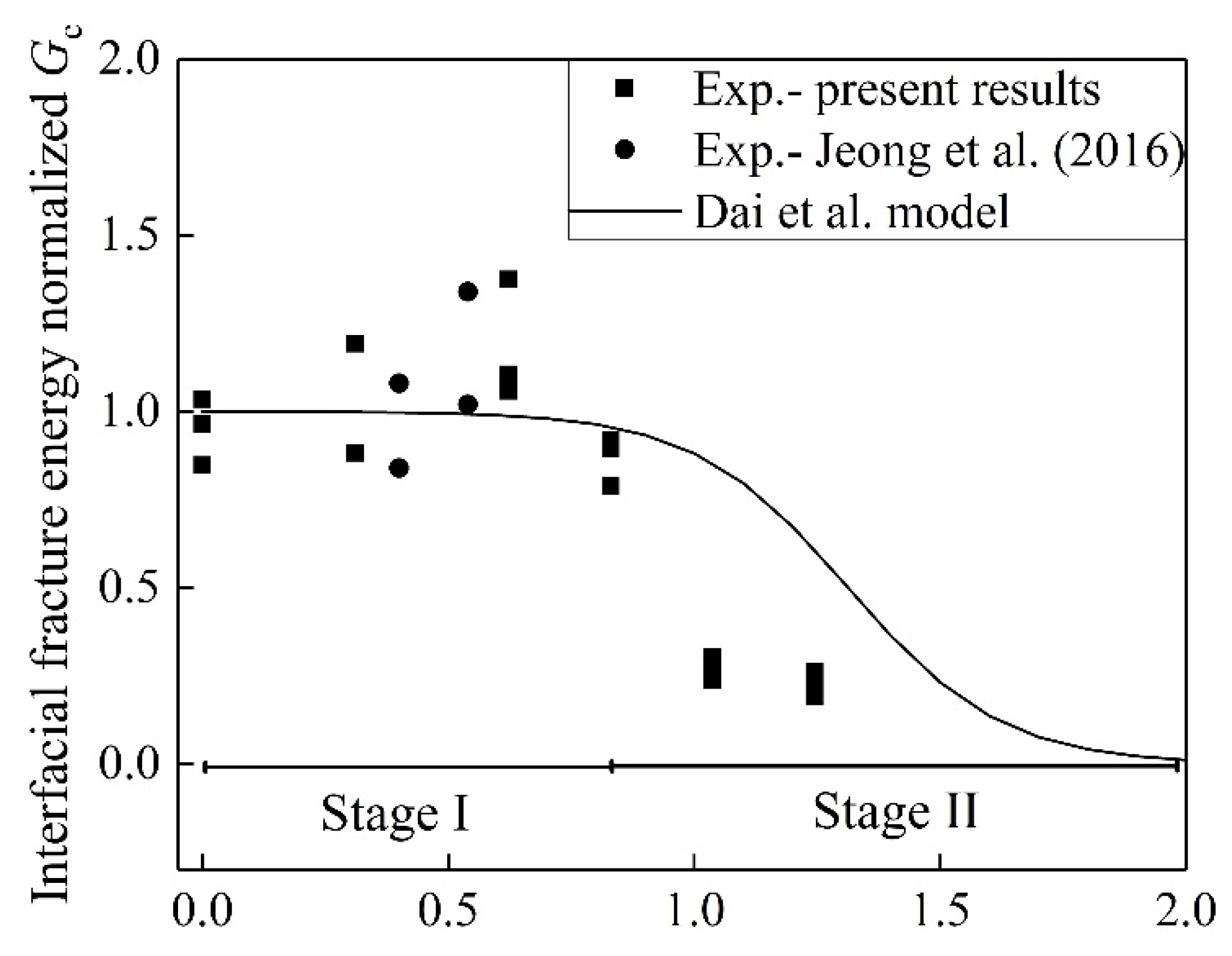
Figure 13 shows the coupled effects of temperature variation and pre-sustained loading on the FRP-to-concrete bond. The model of Dai et al. was adopted to determine the effects of variable temperature on interfacial fracture energy [
9]. “Temperature normalized by
Tg” was defined as the ratio of the temperature at the surface of BFRP to the glass transition temperature. The temperature normalized by Tg between 0 and 2 can be divided into two stages: Stage I and Stage II, as shown in
Figure 13. In the case of Jeong et al. (2016), CFRP sheet was used. Compared to the present study, it is worth noting that the longer pre-sustained load duration of 79 and 153 days were applied for the specimens with temperature normalized
Tg = 0.54 and 0.4, respectively. As shown in
Figure 13, the longer duration insignificantly influenced the bond strength at Stage I. It was reported that less than 50% of the ultimate bond strength involved no-creep bond failure [
23]. It is interesting that the normalized fracture energy increases until the temperature normalized
Tg reaches 0.83. In comparison with the fracture energy determined by the Dai et al. model, Stage I shows that the fracture energy from the experiment is larger below 40 °C. This is attributed to the positive influence of temperature on the interfacial bond. The Dai et al. model ignores the effects of temperature variation on the epoxy because of the post-curing during Stage I.
The interfacial fracture energy for cases above 50 °C is smaller than the results determined by the Dai et al. model. Compared to the prediction of the Dai et al. model, the pre-sustained loading reduces the fracture energy by 62% and 69% for 50 and 60 °C, respectively. This implies that the pre-sustained loading accelerates the deterioration in the interfacial fracture energy.
5. Conclusions
The coupled effects of variation temperature and pre-sustained loading on the bond behavior between BFRP sheets and concrete were studied both experimentally and analytically. Based on the results and discussion, the conclusions are as follows:
(1) Within the pre-sustained loading (35% of fu), the failure mode is primarily cohesion failure in the thin concrete layer at the temperature of 15 and 30 °C. However, the failure mode is changed to primer–concrete interface debonding at the temperature of 40, 50, and 60 °C due to the decrease of the physical bonding and interlocking interaction.
(2) Effects of pre-sustained loading (35% of fu) on the failure load at temperature 15 and 30 °C is insignificant. The coupling of the temperature (i.e., 40, 50, and 60 °C) and pre-sustained loading reduced the failure load by 21%, 56%, and 59%, respectively.
(3) Compared to the temperature at 15 °C, the fracture energy increases by 46% at 30 °C and 11% at 40 °C. However, it reduces by 73% and 77% at 50 and 60 °C, respectively. The effect of the pre-sustained loading has the insignificant influence on the fracture energy at the temperature of 15 and 30 °C. The pre-sustained loading accelerated the degradation of the interfacial bond at the temperature above 30 °C.
(4) The short duration of pre-sustained load (three hours) insignificantly influenced the effective bond length at the temperature of 15 and 30 °C. The effective bond length at the temperature above 30 °C was at least two times larger than that of the control specimens. The effective bond length increased with the temperature.
(5) After three hours of the steady-state test (ST), the strain at the loaded end decreased with increasing temperature. The reduction in strain at the loaded end maintained a stable value at the temperature of 40, 50, and 60 °C.


 ,
, 


