Large Cutting Depth and Layered Milling of Titanium Alloy Thin-Walled Parts


Abstract
:1. Introduction
2. Materials and Methods
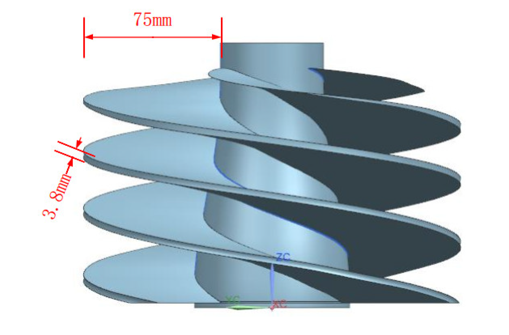
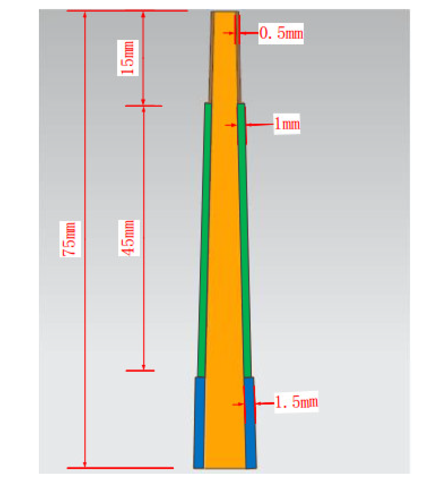
2.1. Experimental Workpiece
2.2. Experimental Conditions
2.3. Experimental Design
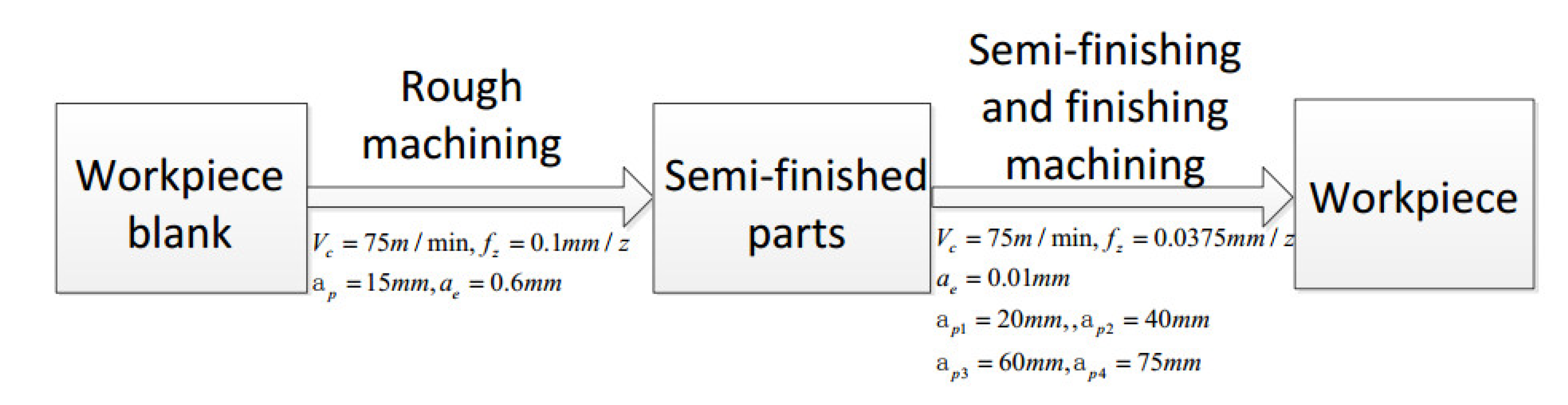
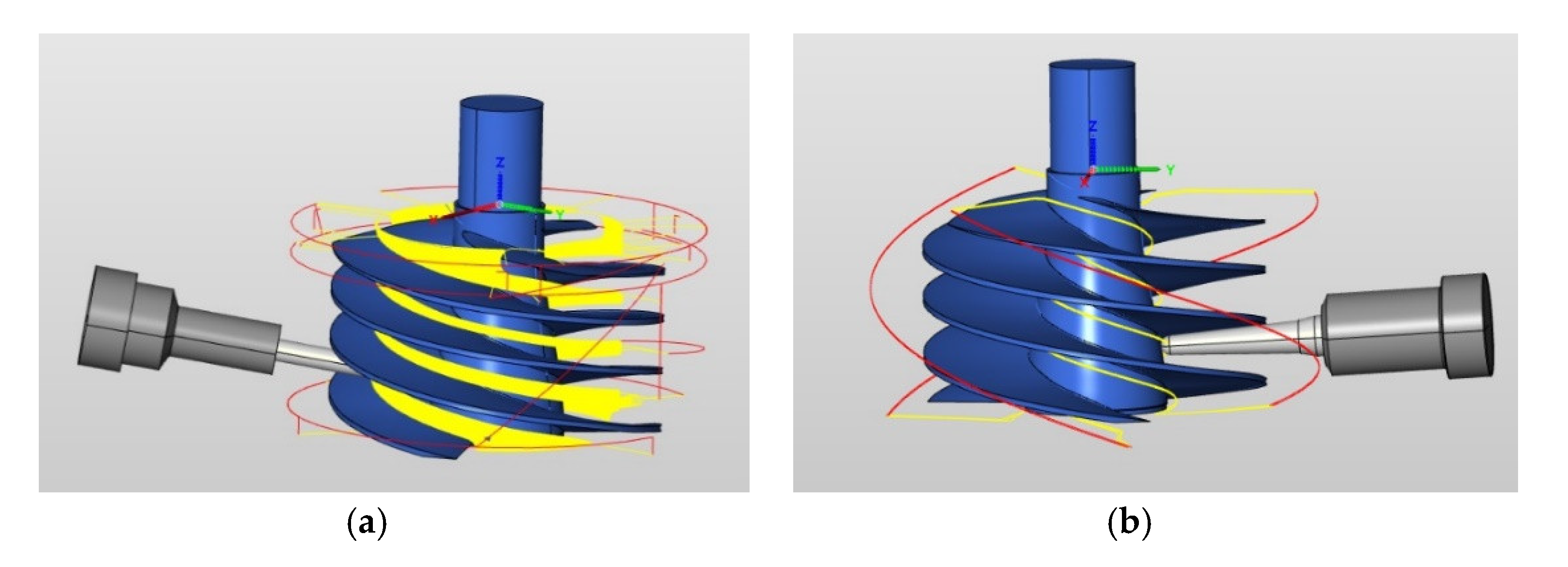
2.3.1. Rough Machining
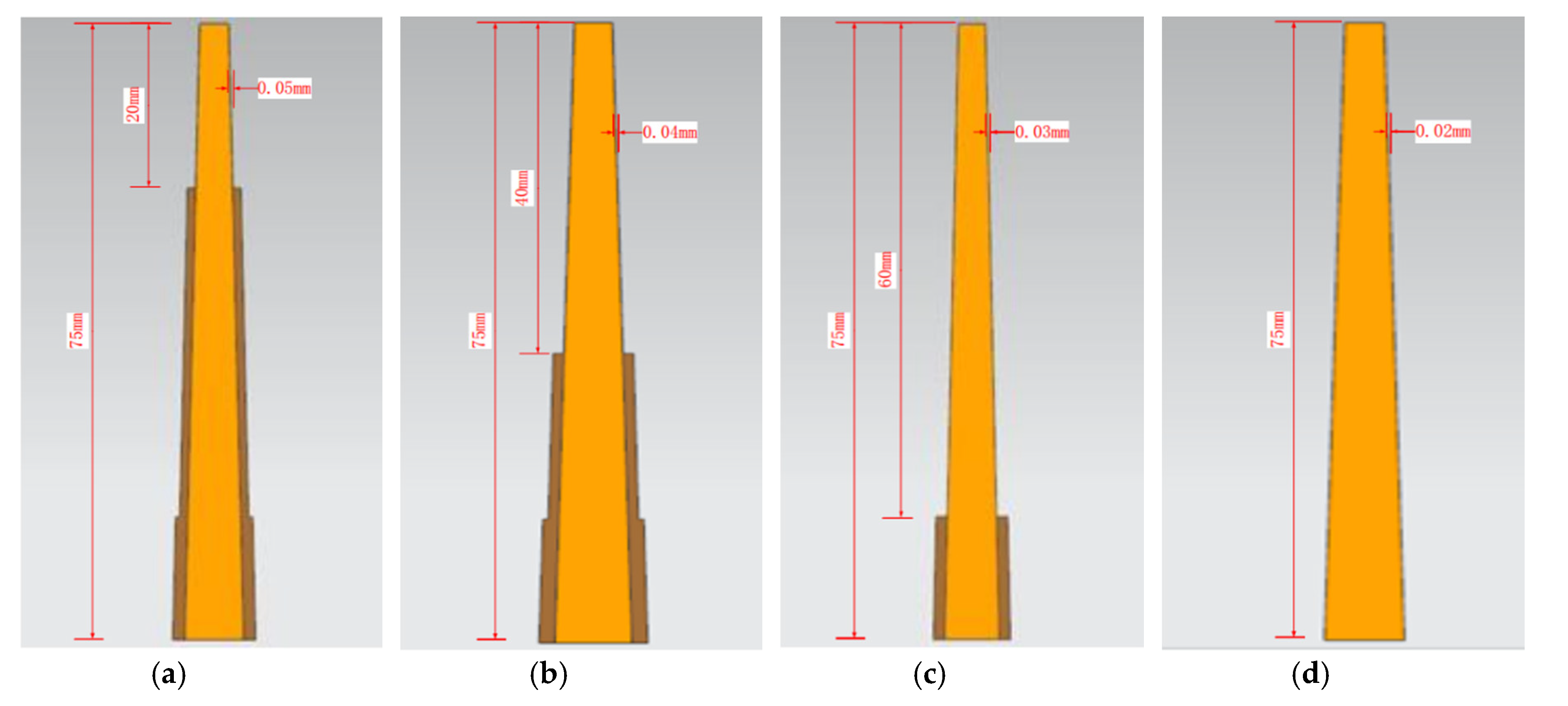
2.3.2. Semi-Finishing Machining and Finishing Machining
3. Machining and Measurement Results
3.1. Machining
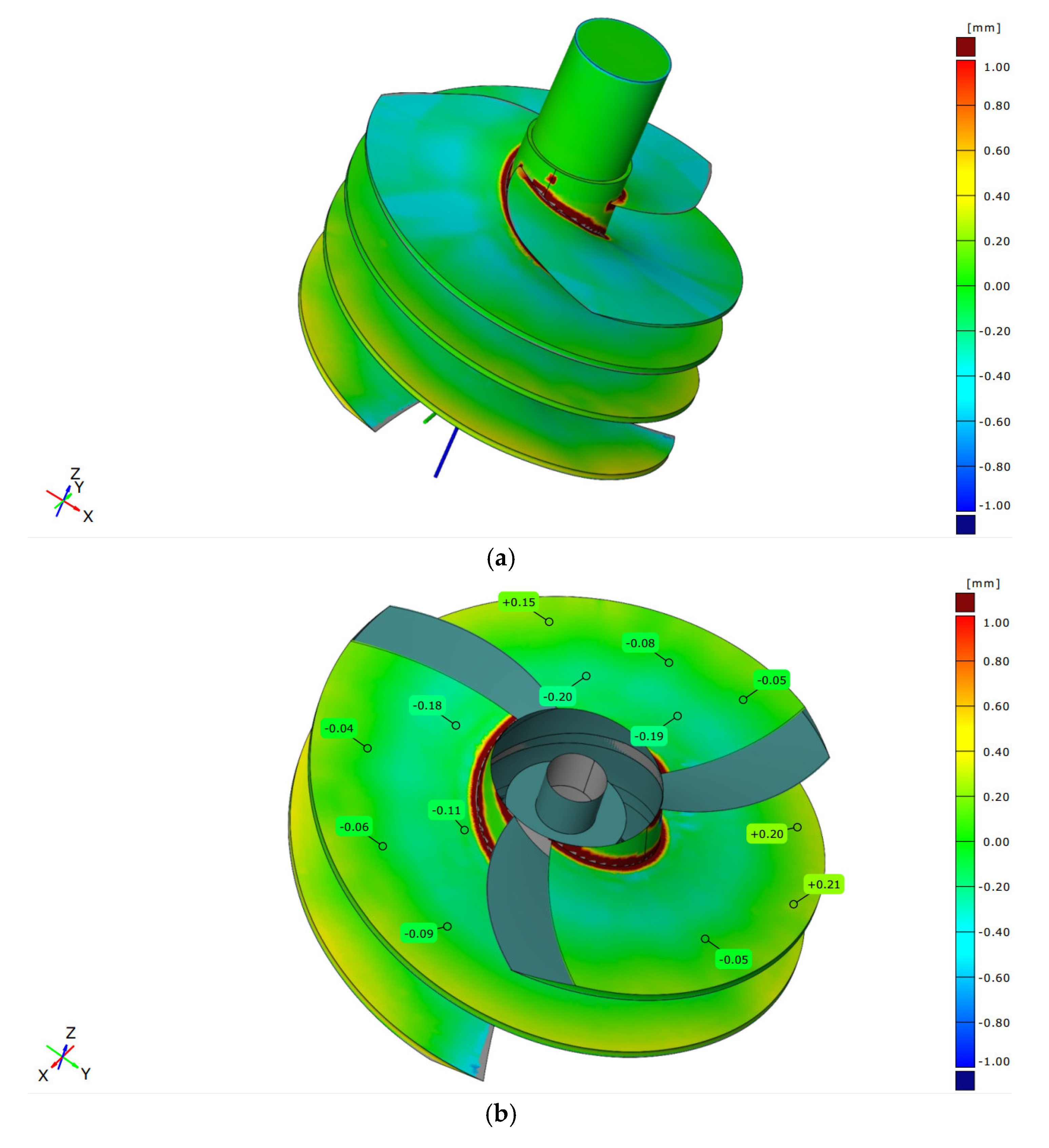
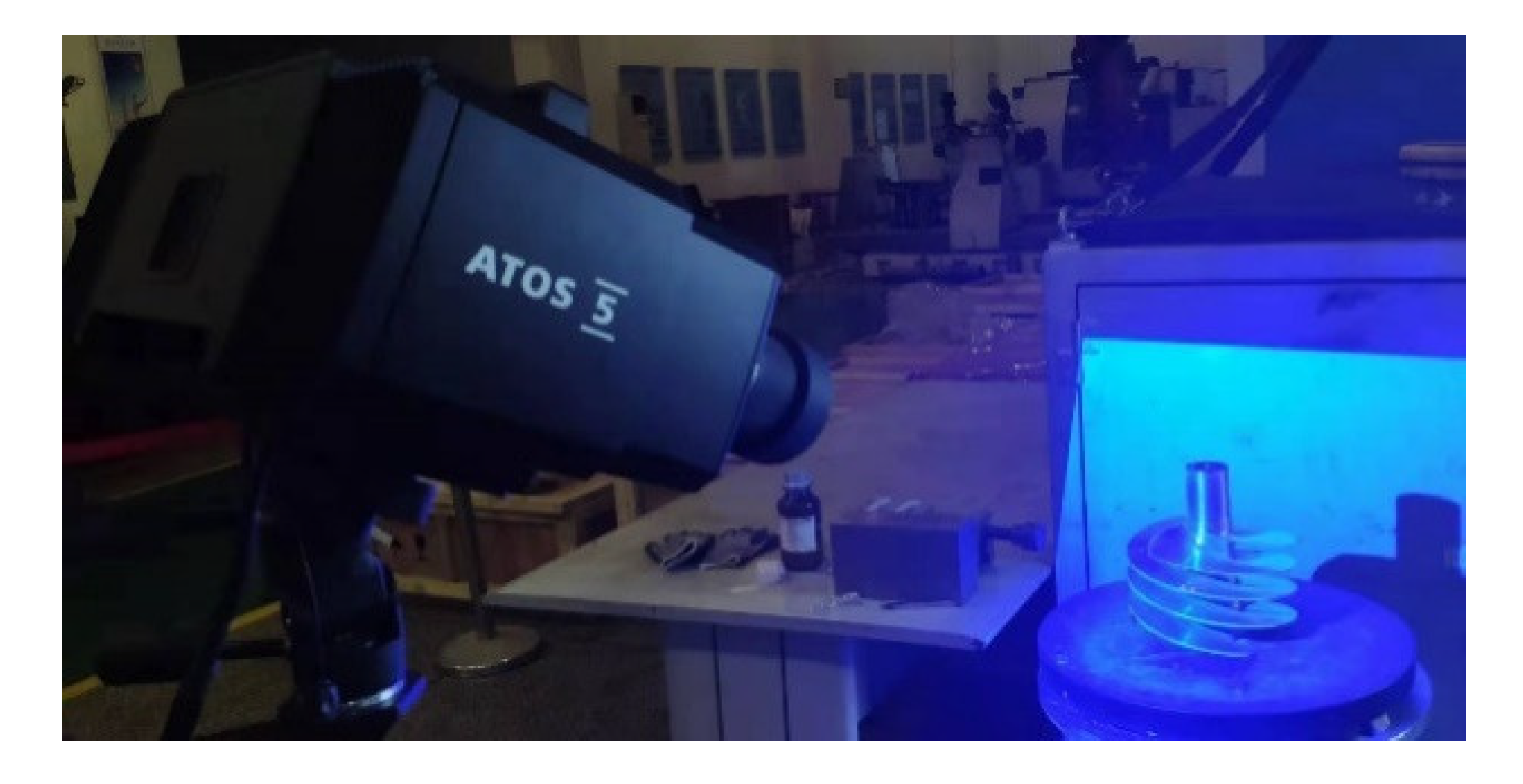
3.2. Contour Accuracy Measurements
4. Conclusions
- In the rough machining stage, a large cutting depth and layer milling method were used to improve efficiency. It takes 87.3 h to complete rough machining under the original processing technology. However, this process took only 52.7 h when using the new processing technology; thus, the machining efficiency was increased by 40%. At the same time, the suitable surface contours of parts were provided for semi-finishing and finishing.
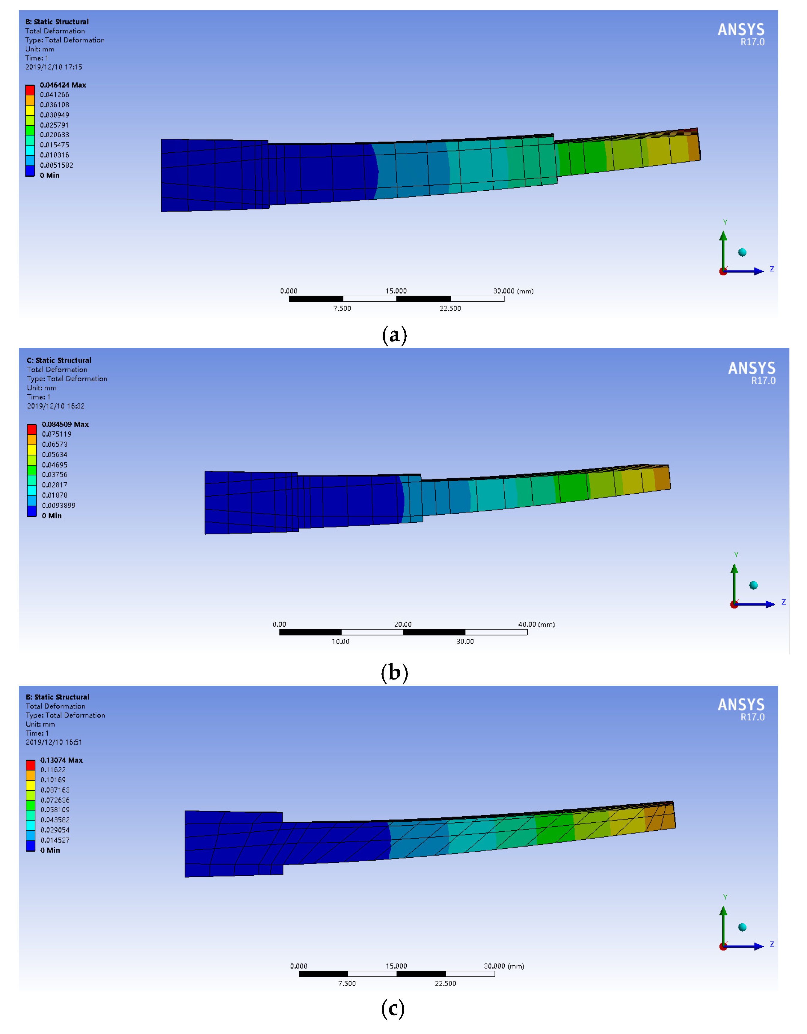
- In the finishing stage, a one-shot forming method was used. The surface of the previous layer needs to be dressed when processing the next layer. The surface contour accuracy of parts was within the range of ± 0.30 mm.
Author Contributions
Funding
Conflicts of Interest
Nomenclature
| vc | cutting speed (m/min) |
| fz | feed per tooth (mm/z) |
| ap | cutting depth (mm) |
| ae | cutting width (mm) |
| F | cutting force (N) |
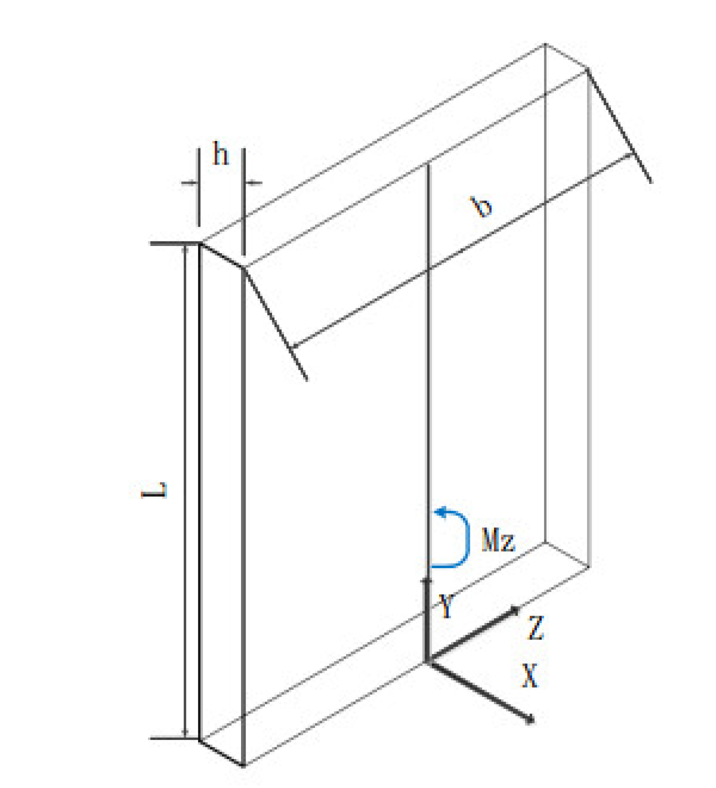
| Mz, My | bending moment (N m) |
| normal stress (N/m2) | |
| Iz, Iy | inertia moment (m4) |
| Wz | modulus of flexural section (m3) |
References
- Rhodes, C.G.; Williams, J.C. The precipitation of α-phase in metastable β-phase Ti alloys. Met. Mater. Trans. A 1975, 6, 2103–2114. [Google Scholar] [CrossRef]
- Kou, Z.; Wan, Y.; Liu, Z.; Cai, Y.; Liang, X. Deformation control in micro-milling of thin-walled structures. Int. J. Adv. Manuf. Technol. 2015, 81, 967–974. [Google Scholar] [CrossRef]
- Chen, W.; Xue, J.; Tang, D.; Chen, H.; Qu, S. Deformation prediction and error compensation in multilayer milling processes for thin-walled parts. Int. J. Mach. Tools Manuf. 2009, 49, 859–864. [Google Scholar] [CrossRef]
- Rai, J.K.; Xirouchakis, P. Finite element method based machining simulation environment for analyzing part errors induced during milling of thin-walled components. Int. J. Mach. Tools Manuf. 2008, 48, 629–643. [Google Scholar] [CrossRef]
- Liu, S.; Zheng, L.; Zhang, Z.; Wen, D. Optimal fixture design in peripheral milling of thin-walled workpiece. Int. J. Adv. Manuf. Technol. 2005, 28, 653–658. [Google Scholar] [CrossRef]
- Herranz, S.; Campa, F.J.; De Lacalle, L.N.L.; Rivero, A.; Lamikiz, A.; Ukar, E.; Sanchez, J.A.; Bravo, U. The milling of airframe components with low rigidity: A general approach to avoid static and dynamic problems. Proc. Inst. Mech. Eng. Part B J. Eng. Manuf. 2005, 219, 789–801. [Google Scholar] [CrossRef]
- Calleja, A.; Bo, P.; González, H.; Barton, M.; De Lacalle, L.N.L. Highly accurate 5-axis flank CNC machining with conical tools. Int. J. Adv. Manuf. Technol. 2018, 97, 1605–1615. [Google Scholar] [CrossRef] [Green Version]
- Li, Z.; Chen, L.; Xu, K.; Gao, Y.; Tang, K. Five-axis Trochoidal Flank Milling of Deep 3D Cavities. Comput. Des. 2020, 119, 102775. [Google Scholar] [CrossRef]
- Bo, P.; González, H.; Calleja, A.; De Lacalle, L.N.L.; Bartoň, M. 5-axis double-flank CNC machining of spiral bevel gears via custom-shaped milling tools—Part I: Modeling and simulation. Precis. Eng. 2020, 62, 204–212. [Google Scholar] [CrossRef] [Green Version]
- Urbikain, G.; Olvera, D.; De Lacalle, L.N.L.; Elías-Zúñiga, A.; Urbicain, G. Stability and vibrational behaviour in turning processes with low rotational speeds. Int. J. Adv. Manuf. Technol. 2015, 80, 871–885. [Google Scholar] [CrossRef]
- Urbikain, G.; De Lacalle, L.N.L. Modelling of surface roughness in inclined milling operations with circle-segment end mills. Simul. Model. Pract. Theory 2018, 84, 161–176. [Google Scholar] [CrossRef]
- Urbikain, G.; De Lacalle, L.L.; Fernández, A.; De Lacalle, L.N.L. Regenerative vibration avoidance due to tool tangential dynamics in interrupted turning operations. J. Sound Vib. 2014, 333, 3996–4006. [Google Scholar] [CrossRef]
- Urbikain, G.; Campa, F.J.; Zulaika, J.-J.; De Lacalle, L.N.L.; Alonso, M.-A.; Collado, V. Preventing chatter vibrations in heavy-duty turning operations in large horizontal lathes. J. Sound Vib. 2015, 340, 317–330. [Google Scholar] [CrossRef]
- Urbicain, G.; De La Calle, L.L. Stability charts with large curve-flute end-mills for thin-walled workpieces. Mach. Sci. Technol. 2018, 22, 585–603. [Google Scholar] [CrossRef]
- Campa, F.J.; De Lacalle, L.N.L.; Lamikiz, A.; Sanchez, J.A.; Lamikiz, A. Selection of cutting conditions for a stable milling of flexible parts with bull-nose end mills. J. Mater. Process. Technol. 2007, 191, 279–282. [Google Scholar] [CrossRef]
- Campa, F.J.; De Lacalle, L.L.; Celaya, A.; De Lacalle, L.N.L. Chatter avoidance in the milling of thin floors with bull-nose end mills: Model and stability diagrams. Int. J. Mach. Tools Manuf. 2011, 51, 43–53. [Google Scholar] [CrossRef] [Green Version]
- Arizmendi, M.; Campa, F.J.; Fernández, J.; De Lacalle, L.N.L.; Gil Del Val, A.; Bilbao, E.; Veiga, F.; Lamikiz, A. Model for surface topography prediction in peripheral milling considering tool vibration. CIRP Ann. 2009, 58, 93–96. [Google Scholar] [CrossRef]
- Bravo, U.; Altuzarra, O.; De Lacalle, L.N.L.; Sanchez, J.A.; Campa, F.J. Stability limits of milling considering the flexibility of the workpiece and the machine. Int. J. Mach. Tools Manuf. 2005, 45, 1669–1680. [Google Scholar] [CrossRef]
- Zhang, Z.; Qi, Y.; Cheng, Q.; Liu, Z.; Tao, Z.; Cai, L. Machining accuracy reliability during the peripheral milling process of thin-walled components. Robot. Comput. Manuf. 2019, 59, 222–234. [Google Scholar] [CrossRef]
- Thepsonthi, T.; Ozel, T. Multi-objective process optimization for micro-end milling of Ti-6Al-4V titanium alloy. Int. J. Adv. Manuf. Technol. 2012, 63, 903–914. [Google Scholar] [CrossRef]
- Datta, R.; Deb, K. A Classical-Cum-Evolutionary Multi-Objective Optimization for Optimal Machining Parameters. In Proceedings of the 2009 World Congress on Nature & Biologically Inspired Computing (NaBIC), Coimbatore, India, 9–11 December 2009; pp. 607–612. [Google Scholar]
- Masoudi, S.; Amini, S.; Saeidi, E.; Eslami-Chalander, H. Effect of machining-induced residual stress on the distortion of thin-walled parts. Int. J. Adv. Manuf. Technol. 2014, 76, 597–608. [Google Scholar] [CrossRef]
- Alexander, I.; Vladimir, G.; Petr, P.; Mihail, K.; Yuriy, I.; Andrey, V. Machining of Thin-walled Parts Produced by Additive Manufacturing Technologies. Procedia CIRP 2016, 41, 1023–1026. [Google Scholar] [CrossRef] [Green Version]
- Meshreki, M.; Kovecses, J.; Attia, H.; Tounsi, N. Dynamics Modeling and Analysis of Thin-Walled Aerospace Structures for Fixture Design in Multiaxis Milling. J. Manuf. Sci. Eng. 2008, 130, 031011. [Google Scholar] [CrossRef]
- Toh, C. Static and dynamic cutting force analysis when high speed rough milling hardened steel. Mater. Des. 2004, 25, 41–50. [Google Scholar] [CrossRef]


| Al | V | Fe | N | C | O | H | Ti |
|---|---|---|---|---|---|---|---|
| 6.0 | 4.0 | 0.3 | 0.05 | 0.1 | 0.2 | 0.0125 | Rest |
| Tensile Strength | Yield Strength | Elongation | Shrinkage |
|---|---|---|---|
| 902 Mpa | 824 Mpa | 10% | 30% |
© 2020 by the authors. Licensee MDPI, Basel, Switzerland. This article is an open access article distributed under the terms and conditions of the Creative Commons Attribution (CC BY) license (http://creativecommons.org/licenses/by/4.0/).
Share and Cite
Zha, J.; Liang, J.; Li, Y.; Zhang, H.; Chen, Y. Large Cutting Depth and Layered Milling of Titanium Alloy Thin-Walled Parts. Materials 2020, 13, 1499. https://doi.org/10.3390/ma13071499
Zha J, Liang J, Li Y, Zhang H, Chen Y. Large Cutting Depth and Layered Milling of Titanium Alloy Thin-Walled Parts. Materials. 2020; 13(7):1499. https://doi.org/10.3390/ma13071499
Chicago/Turabian StyleZha, Jun, Jianxin Liang, Yipeng Li, Huijie Zhang, and Yaolong Chen. 2020. "Large Cutting Depth and Layered Milling of Titanium Alloy Thin-Walled Parts" Materials 13, no. 7: 1499. https://doi.org/10.3390/ma13071499
APA StyleZha, J., Liang, J., Li, Y., Zhang, H., & Chen, Y. (2020). Large Cutting Depth and Layered Milling of Titanium Alloy Thin-Walled Parts. Materials, 13(7), 1499. https://doi.org/10.3390/ma13071499