Article

Improvement of AZ91 Alloy Corrosion Properties by Duplex NI-P Coating Deposition

1
Faculty of Chemistry, Brno University of Technology, Purkyňova 464/118, 602 00 Brno, Czech Republic
2
Institute of Physic of Materials, Academy of Science Czech Republic, Žižkova 22, 616 62 Brno, Czech Republic
*
Author to whom correspondence should be addressed.
Materials 2020, 13(6), 1357; https://doi.org/10.3390/ma13061357
Submission received: 18 February 2020 / Revised: 14 March 2020 / Accepted: 15 March 2020 / Published: 17 March 2020
(This article belongs to the Special Issue Corrosion and Corrosion Protection for Light Metals/Alloys)

Abstract

:
The corrosion behavior of duplex Ni-P coatings deposited on AZ91 magnesium alloy was studied. The electroless deposition process of duplex Ni-P coating consisted in the preparation of low-phosphorus Ni-P coating (5.7 wt.% of P), which served as a bond coating and high-phosphorus Ni-P coating (11.5 wt.% of P) deposited on it. The duplex Ni-P coatings with the thickness of 25, 50, 75 and 100 µm were deposited on AZ91 magnesium alloy. The electrochemical corrosion behavior of coated AZ91 magnesium alloy was investigated by electrochemical impedance spectroscopy and potentiodynamic polarization method in 0.1 M NaCl. Obtained results showed a significant improvement in the corrosion resistance of coated specimens when compared to uncoated AZ91 magnesium alloy. From the results of the immersion tests in 3.5 wt.% NaCl, 10% solution of HCl and NaOH and 5% neutral salt spray, a noticeable increase in the corrosion resistance with the increasing thickness of the Ni-P coating was observed.

1. Introduction

Due to low weight, magnesium and its alloys show great potential in the field of automotive, aerospace, and electrochemical applications [1,2,3]. Magnesium alloys have low density, high modulus, good strength to weight ratio and physical properties [4]. However, their use is limited because of low corrosion resistance and poor wear properties. The electrochemical treatment of magnesium alloy surface is difficult due to their high chemical affinity to acid aqueous solutions [5]. On the other hand, performed surface treatment, which can improve the corrosion and wear resistance of magnesium alloys, is very important for many applications. The electroless conversion or thermally sprayed coatings, organic or ceramic coatings, varnishes are appropriate representatives to improve Mg alloys’ surface resistance against the corrosive environment and mechanical damaging in the industrial applications [6,7].
The application of electroless Ni-P coating is a very promising option to satisfy the demands of industry. The applications of electroless deposited nickel coating as a protective layer increase. It is characterized by high hardness, good wear, and high corrosion resistance, and the coating is uniform with no restriction on the shape of deposited substrate [8].
As the literature indicates [7,8,9], Ni-P coating can be divided into three groups based on the phosphorus content: low-phosphorus Ni-P coatings containing 1–5 wt.% of P, medium-phosphorus Ni-P coatings containing 6–9 wt.% of P and high-phosphorus Ni-P coatings containing 10–13 wt.% of P. The properties of each individual group are completely different. Some studies [10,11] show that low-phosphorus Ni-P coatings in the as-deposited state are crystalline or microcrystalline. Medium-phosphorus coatings are microcrystalline or form a mixture of amorphous and microcrystalline phases. High-phosphorus Ni-P coatings are completely amorphous. Low-phosphorus coatings are characterized by higher hardness and wear resistance than high phosphorus ones [9]. However, high-phosphorus Ni-P coatings are characterized by excellent corrosion resistance due to the absence of grain boundaries and other inhomogeneities, which can serve as active sites for the corrosion attack [7].
Lo et al. [12] studied the effect of phosphorus content on electrochemical behavior of coated materials in 3.5 wt.% NaCl. The authors reported that the corrosion potential, Ecorr, was shifted to more negative values, and the anodic current density increased in the case of low-phosphorus Ni-P coatings when compared to high-phosphorus Ni-P coatings. The polarization curves also showed that with the increase of phosphorus content in the deposited Ni-P coatings, significant decrease in anodic current in neutral and alkaline NaCl solutions was observed. The same results were reached in the case of electrochemical impedance spectroscopy in neutral NaCl solution. Low-phosphorus Ni-P coating (4.8% P) reached the polarization resistance Rp of 8442 Ω·cm2, and medium-phosphorus coating (8% P) reached the polarization resistance of 14,301 Ω·cm2. The high-phosphorus coatings formed 11% and 12.8% P the polarization resistances of 18,530 and 25,383 Ω·cm2 reached, respectively. The same trend was observed in alkaline NaCl solution. These results, correlated to the values given in the work of Gu et al. [13] where high-phosphorus Ni-P coatings (11.5% of P) reached the lower corrosion current density and higher corrosion potential when compared to low- (2.4% of P) and medium-phosphorus (8.8% of P) ones.
It is self-evident that the corrosion resistance is not only dependent on the phosphorus content but also on the thickness of the coating [14,15]. The corrosion tests such as the neutral salt spray (NSS) and immersion tests are an integral part of the quality control of corrosion protection of the coatings produced on the substrate. A corrosive medium such as salt, acid or alkali solution can be used. Zhang et al. [16] studied the corrosion resistance of the medium-phosphorous Ni-P coating (5.6% P) deposited on AZ91 magnesium alloy by the immersion test in 10% HCl solution and by polarization measurement in 3.5% NaCl. The results indicate that the immersion time in 10% HCl increased with increasing thickness of coating. The Ni-P coating with a thickness of ~7 µm failed after less than 10 min whereas the Ni-P coating with a thickness of ~28 µm failed after 45 min. Based on the results of potentiodynamic measurement in 3.5% NaCl, a significant shift to more electropositive potential –0.781 V and a corrosion current density decrease to 17.79 µA·cm−2 were observed.
Zhang et al. [17] studied the corrosion behavior of duplex Ni-P/Ni-B coating on AZ91 alloy in 5% NaCl NSS. As the authors indicate, no noticeable degradation of the coating was observed after 50 h of the experiment.
The aim of this paper is the study of the corrosion resistance of duplex Ni-P coatings deposited on AZ91 magnesium alloy. The first layer is a low-phosphorus deposit, and the second layer is a high-phosphorus one. The corrosion behavior of the coating was determined by means of potentiodynamic measurements, electrochemical impedance spectroscopy in 0.1 M NaCl solution, immersion test in acid, neutral, alkali environment and neutral salt spray test. The implementation of these experiments in various environments provides a primary comprehensive view on the corrosion behavior of duplex Ni-P coatings on AZ91magnesium alloy.

2. Experimental Material and Procedures

AZ91 magnesium alloy samples with the dimensions of approx. 20 mm × 20 mm × 7 mm were used as a substrate. The chemical composition of the substrate material determined using Glow-Discharge Optical Emission Spectroscopy (GDOES) is listed in Table 1.
The samples of AZ91 magnesium alloy were ground using 1200 SiC grit abrasive papers and then washed in distilled water and isopropyl alcohol and dried by hot air. To remove impurities from the samples surface, degreasing in an alkaline solution bath as a pre-treatment was applied (Table 2). After degreasing and cleaning the samples in distilled water and isopropyl alcohol, the surface activation in acid solution followed. The samples were again cleaned in distilled water and isopropyl alcohol and dried.
After the pre-treatment, the samples were immersed into the low-phosphorus electroless nickel plating bath. Based on the coating time, the final thicknesses of created duplex Ni-P coatings were gained: 25, 50, 75 and 100 µm [9]. In the case of Ni-P coatings with required final thickness of 25 and 50 µm, the deposition of low-phosphorus interlayer proceeded for 1.5 h. The thickness of low-phosphorus Ni-P interlayer was 14 µm. The deposition of low-phosphorus interlayer for 2 h was used in the case of Ni-P coatings with the final required thickness of 75 and 100 µm. The thickness of low-phosphorus Ni-P interlayer was in this case of 18 µm. The samples with deposited low-phosphorus interlayer were then immersed into the NiChem HP 1151 (Atotech) high-phosphorus electroless nickel bath for a defined time, as stated in Table 2.
The microhardness of deposited layers of duplex Ni-P coating was measured using LECO AMH55 microhardness tester (Saint Joseph, MO, USA). The microhardness was measured according to the Vickers method under applied load of 25 g for 10 s. The measurement was performed on the coated sample cross-cut mounted into epoxy resin prepared by standard metallographic methods (grinding and polishing).
The average elemental content and elemental mapping of deposited duplex Ni-P coating were determined using the Zeiss EVO LS-10 scanning electron microscope (SEM) (Carl Zeiss Ltd., Cambridge, UK) equipped with an energy-dispersive X-ray spectroscopy (EDS) Oxford Instruments Xmax 80 mm2 detector (Oxford Instruments plc, Abingdon, UK) and AZtec software analysis (version 2.4).
The short-time potentiodynamic measurements were performed in 0.1 M NaCl solution at room temperature using the Bio-Logic VSP-300 potentiostat/galvanostat (BioLogic, Seyssinet-Pariset, France). Measured samples with analyzed area of 1 cm2 served as a working electrode. Saturated calomel electrode (SCE) was used as a reference electrode and Pt wire as a counter-electrode.
Open circuit potential (OCP) variations with time were recorded up to 10 min of exposure. Afterward, Tafel plot was obtained by carrying out partial potentiodynamic polarization in the potential range from −100 mV to 200 mV from OCP at the potential scan rate of 1 mV/s.
Electrochemical impedance spectroscopy (EIS) measurements were performed in 0.1 M NaCl solution at room temperature for 5 min, 1, 2, 4, 8, 12, 24, 48, 72, 96 and 168 h within the frequency range from 100 kHz to 10 mHz. The perturbation amplitude was set up to 5 mV.
The immersion corrosion tests were carried out on samples with deposited Ni-P coatings with various thicknesses: 25, 50, 75 and 100 µm. The samples were immersed in three solutions at room temperature, including 3.5 wt.% NaCl solution, 10 wt.% NaOH solution and 10 wt.% HCl solution. The exposure time was set based on the evolution of hydrogen. The experiment was stopped after the first hydrogen bubble had arisen from the surface of immersed sample.
The neutral salt spray testing was performed on coated samples as well. The samples were exposed to 5 wt.% NaCl solution at the temperature of 35 °C in LIEBISCH SKB 400 A-TR (LIEBISCH Laboratortechnik, Germany) corrosion chamber. The NSS testing was conducted according to the ASTM B117.6 standard. All experiments were performed on three samples for each coating thickness.

3. Results and Discussion

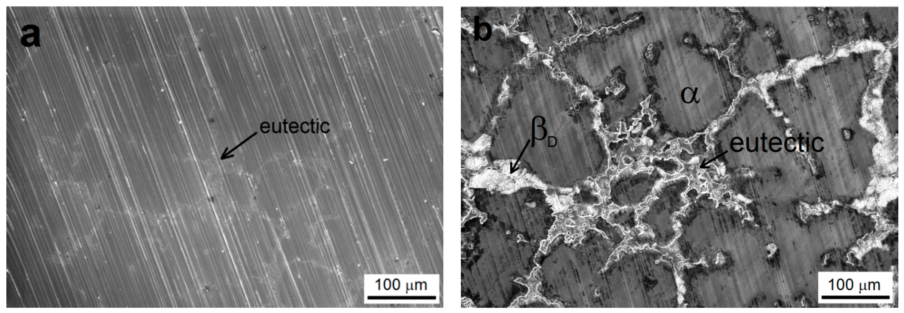
3.1. Pre-Treated AZ91 Magnesium Alloy Samples’ Surface Morphology

The surface of ground AZ91 magnesium alloy is shown in Figure 1a. The alkaline degreasing seems to have no significant influence on material surface roughness. Scratches after grinding are still obvious. On the other hand, the microstructure of the material was partially revealed; eutectic (α + βD phase) areas can be identified.
The etched surface of the AZ91 alloy after the immersion in the acid bath is shown in Figure 1b. The acid etching (surface activation) has revealed the microstructure of AZ91 alloy, and the presence of α solid solution grains, eutectic (α + βD phase) and discontinuous precipitate βD (Mg17Al12) was evident [18].
The surface pre-treatment of the AZ91 magnesium alloy has a great importance for the resulting quality of deposited Ni-P coatings and influences the corrosion properties of coated material [19,20,21]. Due to the galvanic coupling, preferred nucleation of Ni occurs on the areas of Mg17Al12 phase, and then, it spreads to the eutectics and next to α solid solution grains [22,23,24]. However, due to the heterogeneous phase composition of AZ91, the preferential nucleation of nickel on the areas of Mg17Al12 phase should lead to non-uniform Ni-P coating growth. As a result of non-uniform covering of the magnesium substrate surface, a lower quality of deposited Ni-P coating can occur.

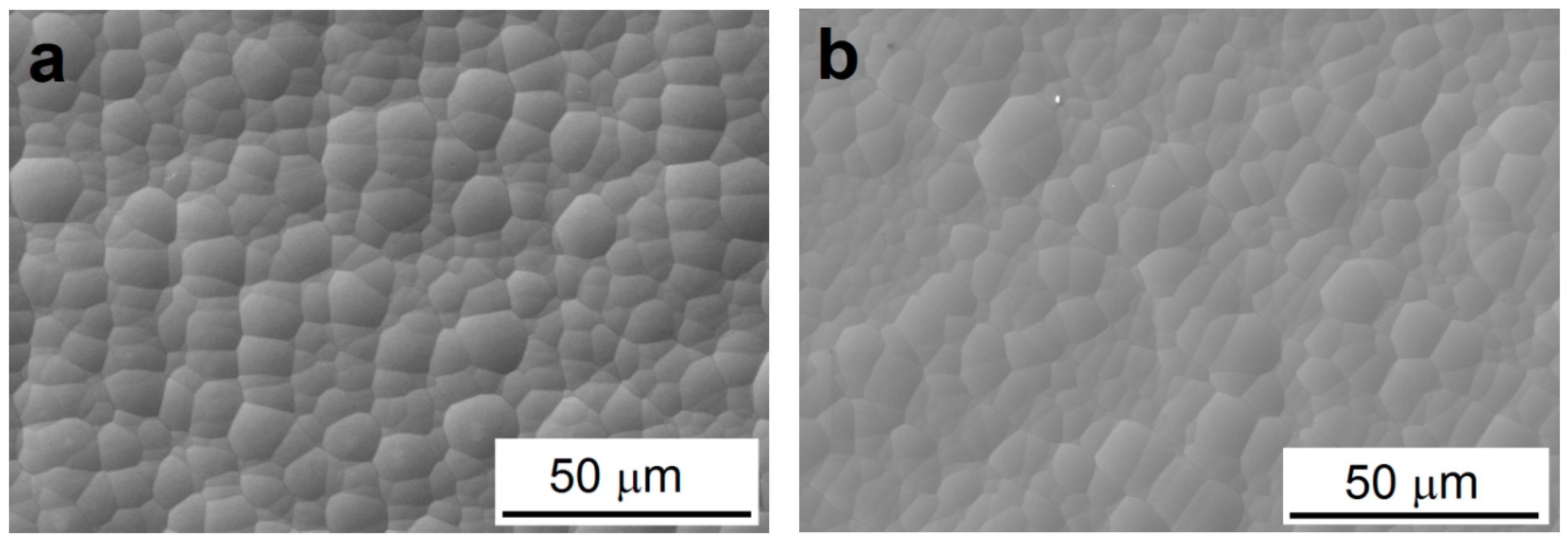
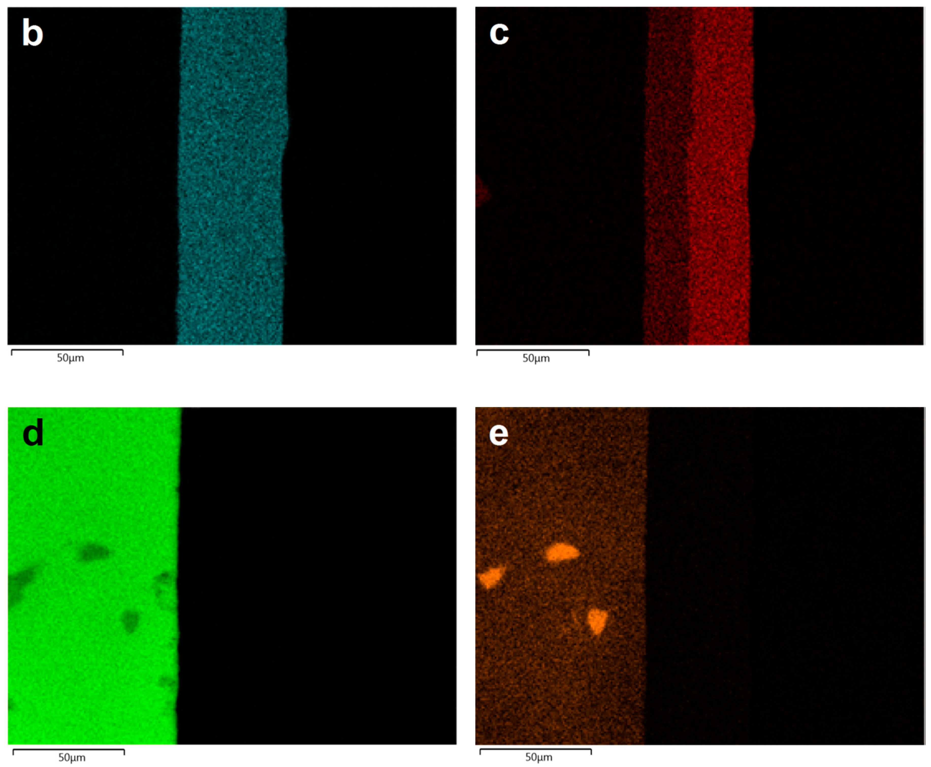
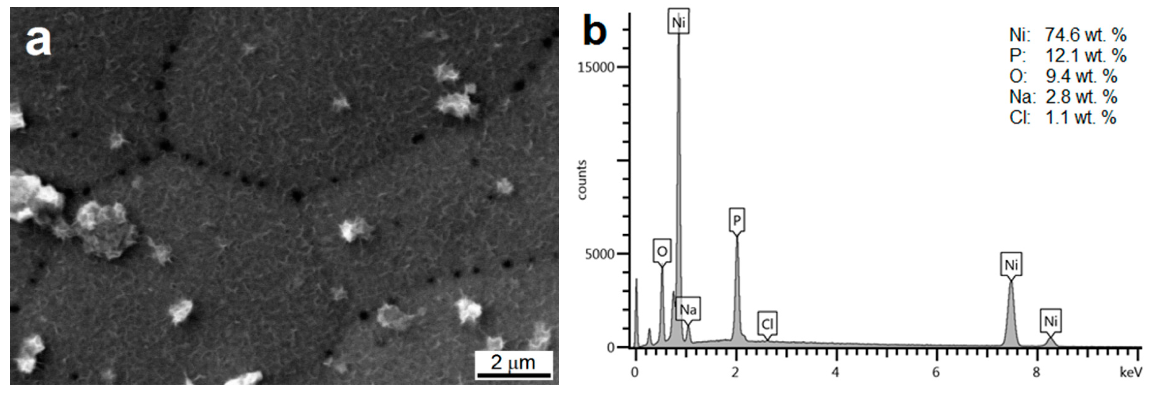
3.2. Morphology and Chemical Composition of Deposited NI-P Coatings

As can be seen in Figure 2, deposited Ni-P coatings exhibit spherical nodular structure without visible defects, no micropores in the case of both coatings, low-phosphorus Ni-P interlayer and high-phosphorus Ni-P topcoat can be observed. All coatings exhibited the same surface morphology and character. No coating structure coarsening was observed due to increasing coating thickness.
According to the literature [8,25] the porosity of Ni-P coatings decreases with increasing the thickness of coating. The electroless Ni-P coatings were shown to contain micropores in their volume when the coating time was lower than 80 min (thickness over 10 µm).
Figure 3 shows the cross-section micrograph of duplex Ni-P coating formed by a low-phosphorus interlayer with an average phosphorus content of 5.7 wt.% (~14 µm) and a high-phosphorus topcoat with an average phosphorus content of 11.5 wt.% (~36 µm). The deposited duplex Ni-P coating exhibits no oxide layer between AZ91 magnesium substrate and deposited Ni-P interlayer due to suitable pretreatment and deposition process. No visible defects or cracks were observed in the deposited Ni-P layer neither on the layer/substrate interface (Figure 3a). From the elemental EDS mapping (Figure 3), it was observed that each deposited Ni-P layer of duplex coating exhibits a homogeneous uniformity of chemical composition. The homogeneous composition of each layer of the duplex coating was provided by a sufficient amount of Ni2+ ions in the electroless nickel bath [7].
The areas of higher concentration of Al were observed on the Mg alloy surface. They can be ascribed to the presence of Mg17Al12 phase in the substrate microstructure (Figure 3e).

3.3. Microhardness of Deposited Coatings

The microhardness of deposited low-phosphorus Ni-P interlayer and high-phosphors Ni-P topcoat of duplex Ni-P coating, measured on the polished cross-section, was determined to be 620 ± 20 HV 0.025 and 580 ± 10 HV 0.025, respectively. The microhardness of cast AZ91 magnesium alloy was determined to be 70 ± 10 HV 0.025. It is evident that the low-phosphorus Ni-P interlayer has higher microhardness when compared to the high-phosphorus Ni-P coating. As mentioned in the literature [7,26], observed microhardness difference can be explained by the character of microstructure of the coatings. The coatings with higher phosphorus content are amorphous, as described in [7,27]. In the case of crystalline (low-phosphorus) Ni-P coatings, the ability to deform the crystalline lattice is substantially lower than that of the amorphous (high-phosphorus) Ni-P coatings. These differences in the material response to the deformation/loading result in higher hardness of coatings with crystalline structure when compared to the amorphous ones [28]. Agarwala and Agarwala [11] state that the hardness of deposited Ni-P coatings is strictly affected by their elemental composition. In their study, the low-phosphorus Ni-P coatings (2–3 wt.% of P) reached the hardness of 700 HV, and the high-phosphorus Ni-P coatings (10–12 wt.% of P) reached the hardness of 510 HV. In agreement with their observations, also in the work of Czagany and Baumli [29], the microhardness of the coatings decreased with increasing phosphorus content. As the authors stated, the highest microhardness (634 HV0.01) was reached for the coating containing 3.67 wt.% of P while the lowest microhardness (363 HV0.01) was reached for the coating with 13.48 wt.% of P.

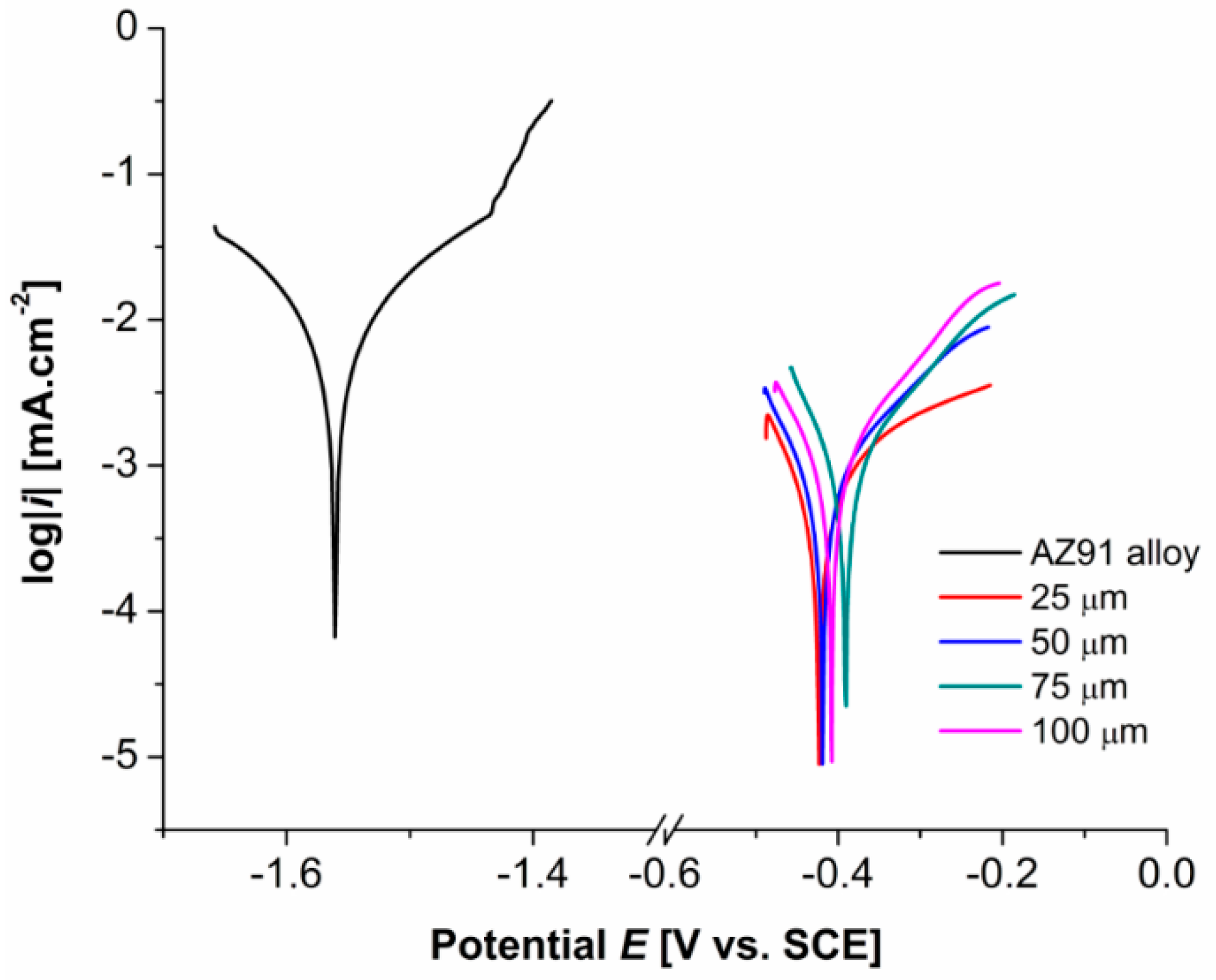
3.4. Electrochemical Polarization Measurements

Figure 4 shows typical potentiodynamic curves of AZ91 magnesium alloy and deposited Ni-P coatings on AZ91 alloy in 0.1 M NaCl. Measured values of the corrosion potential, Ecorr, and the corrosion current density, icorr were determined using the Tafel analysis, and their values are stated in Table 3. The samples of AZ91 alloy were ground (SiC no.1200 paper) directly prior to the measurement to remove the layer of oxides created on the surface of the sample due to the Mg reactivity.
For the AZ91 alloy, the hydrogen evolution (Equation (2)) is the main reaction on the cathodic branch of the polarization curve [3,23]. According to [30], AZ91 magnesium alloy dissolves in the corrosive aqueous solution forming Mg(OH)2 as described by Equations (1)–(3).
Mg     Mg 2 +   +   2 e -
2 H 2 O   +   2 e -     H 2   +   2 OH -
Mg 2 +   +   2 OH -     Mg ( OH ) 2
Created Mg(OH)2 compounds should form a protective layer against the following corrosion. This layer is insoluble in pure water but is not fully compacted and hence contains many micropores and microcracks. Moreover, in the presence of Cl ions in the solution, this layer is being constantly disrupted. As a result, MgCl2 soluble in the water solution (corrosive environment) is formed (Equation (4)) [3,21,31]. The formation of MgCl2 disrupts the compactness of protective Mg(OH)2 layer.
Mg ( OH ) 2   +   2 Cl -     MgCl 2   +   2 OH -
This reaction results in the increase of pH value of corrosive solution due to the release of OH ions into the solution [19].
The pitting corrosion attack on AZ91 alloy samples can be observed on the anodic branch of the potentiodynamic curve, Epit ≈ −1.4 V (Figure 4), where a relatively sharp increase in the corrosion current density occurred.
It is evident that the Ecorr of all specimens with deposited Ni-P coatings are significantly shifted to more electropositive values, and their polarization current density decreased by two orders of magnitude when compared to uncoated AZ91 alloy. The determined values characterizing the sample behavior form the thermodynamic and kinetic points of view are shown in Table 3. Prepared Ni-P coatings showed an increase in the corrosion resistance of the AZ91 magnesium alloy.
From the thermodynamic point of view, based on the short-time potentiodynamic measurements, a significant improvement of corrosion properties of coated Mg alloy was determined. The values of the Ecorr were determined for all coated materials to be almost the same. All coatings exhibit very similar protection against the corrosion. Moreover, no pitting attack was observed on tested coated specimens.
From the kinetic point of view, the corrosion rate of 25–75 µm thick Ni-P coatings is approximately the same. However, the lowest icorr 0.358 µA·cm−2 was observed in the case of 25 µm thick duplex Ni-P coating, as shown in Table 3. A slight increase in icorr and the decrease in Ecorr was observed in the case of 100 µm thick Ni-P coating when compared to other coatings.
Further reduction of the corrosion current density and thus the corrosion rate of AZ91 alloy could be achieved, for example, by the co-deposition of ceramic particles in the Ni-P matrix [32]. If the ceramic particles are evenly distributed in the Ni-P matrix, the contact surface between the Ni-P matrix and the corrosive environment is reduced, which leads to the reduction of the corrosion rate. Hajiali Fina and Amadeh [33] observed that the Ni-P/nanoSiC composite coatings, deposited from the electroless nickel bath containing 15 g·l−1 of SiC nanoparticles, significantly improve the corrosion resistance of AZ91 magnesium alloy. The corrosion current density decreased from 0.13 mA·cm−2 for the uncoated alloy to 1.74·10−6 mA·cm−2 for the alloy with composite coating. The authors explained this fact by the theory that co-deposited SiC nanoparticles can change the corrosion path or even prevent its progress. The co-deposition of these nanoparticles in the Ni-P matrix can change the microstructure of the coating from columnar to coaxial. Moreover, present SiC nanoparticles can reduce the number of submicron defects in Ni-P coating and thus limit the penetration of the corrosive media to the coated substrate.
A significant reduction of Ecorr and icorr was observed also in the case of electroless Ni-P coatings with co-deposited carbon nanotubes (CNT) [34]. Plain Ni-P coating showed the corrosion potential of −0.411 V and the corrosion current density of 0.64 µA·cm−2. By the incorporation of CNT into the Ni-P matrix, the corrosion potential raised up to −0.292 V, and the corrosion current density decreased to 0.29 µA·cm−2.

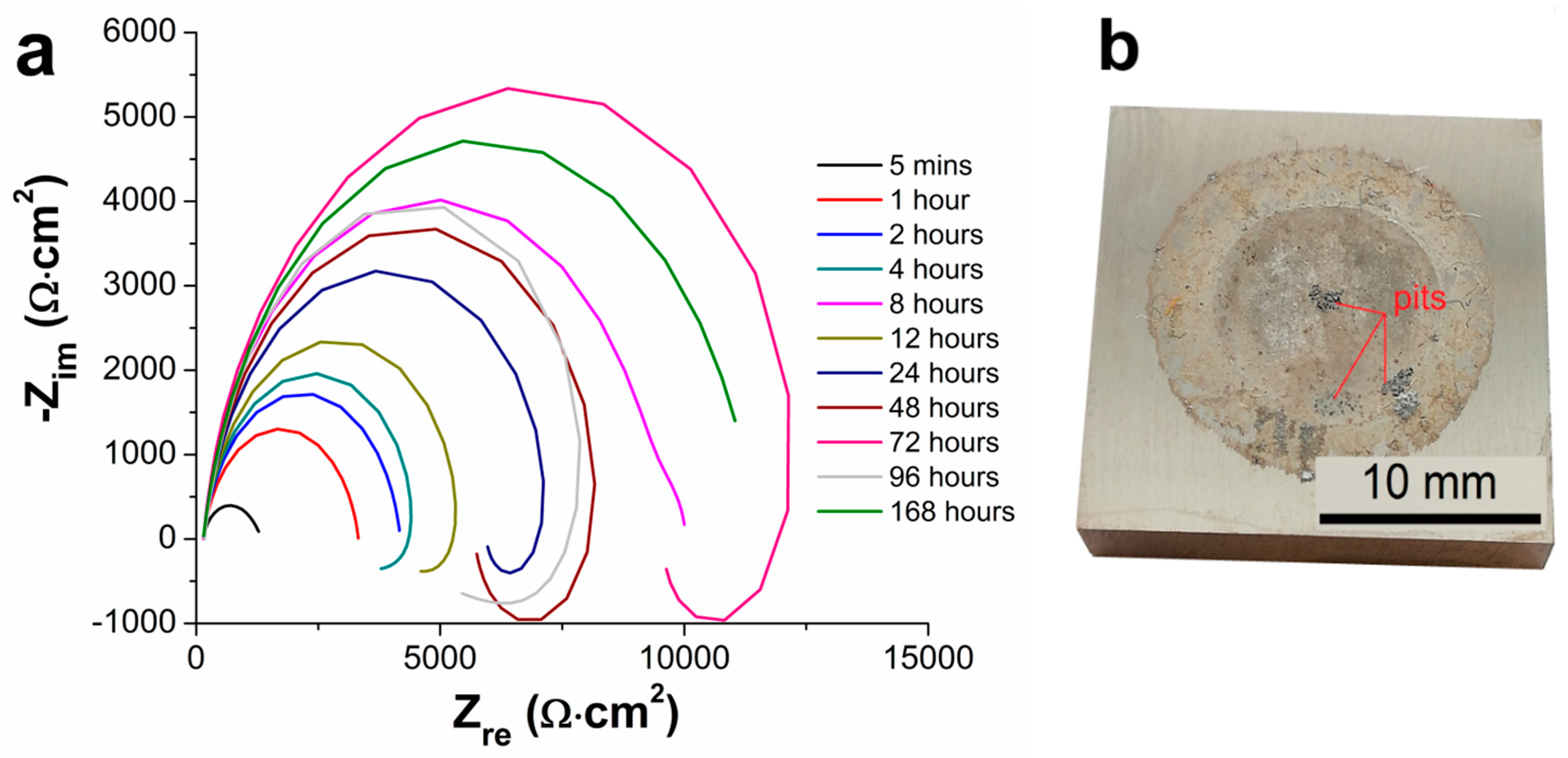
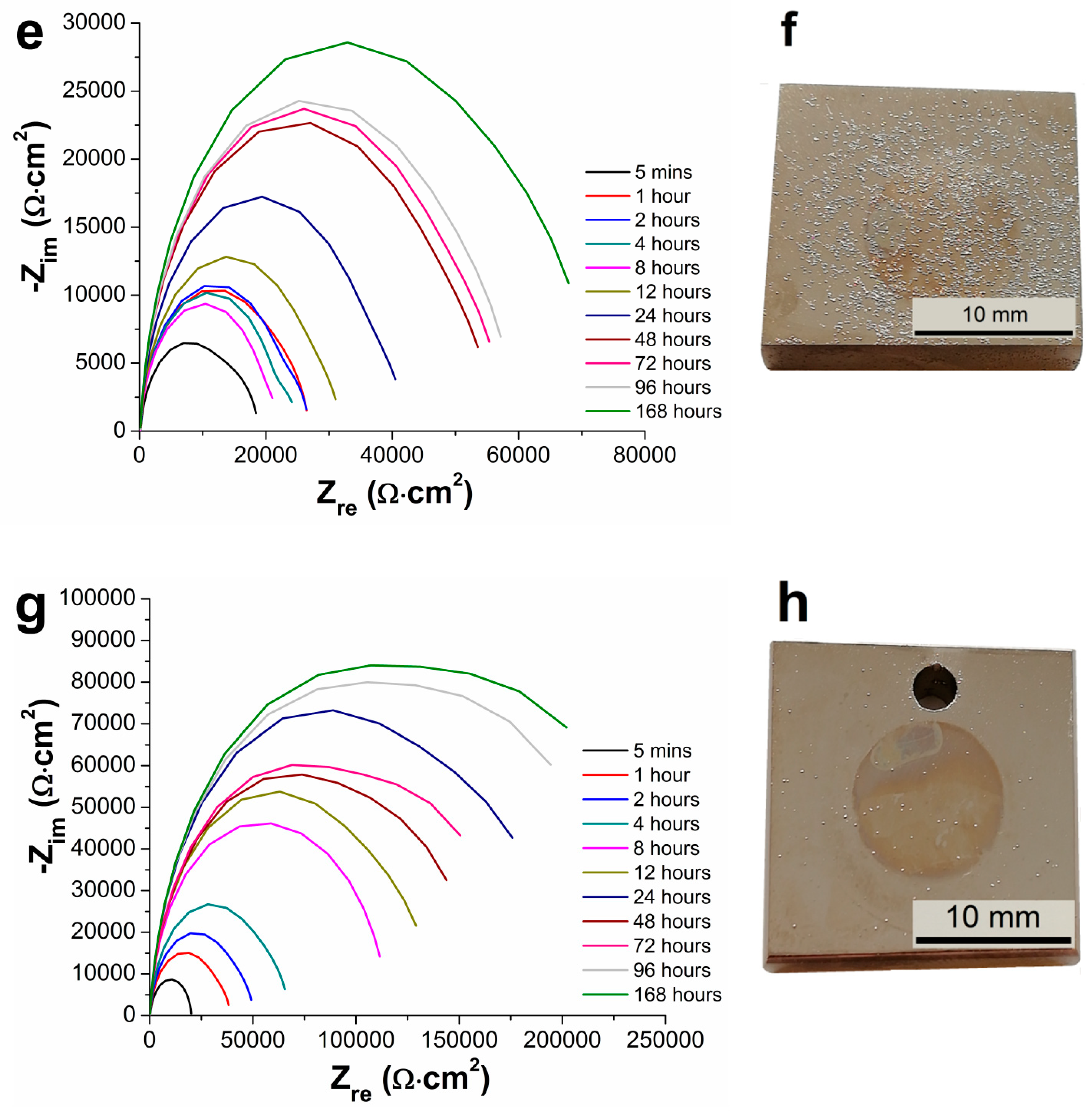
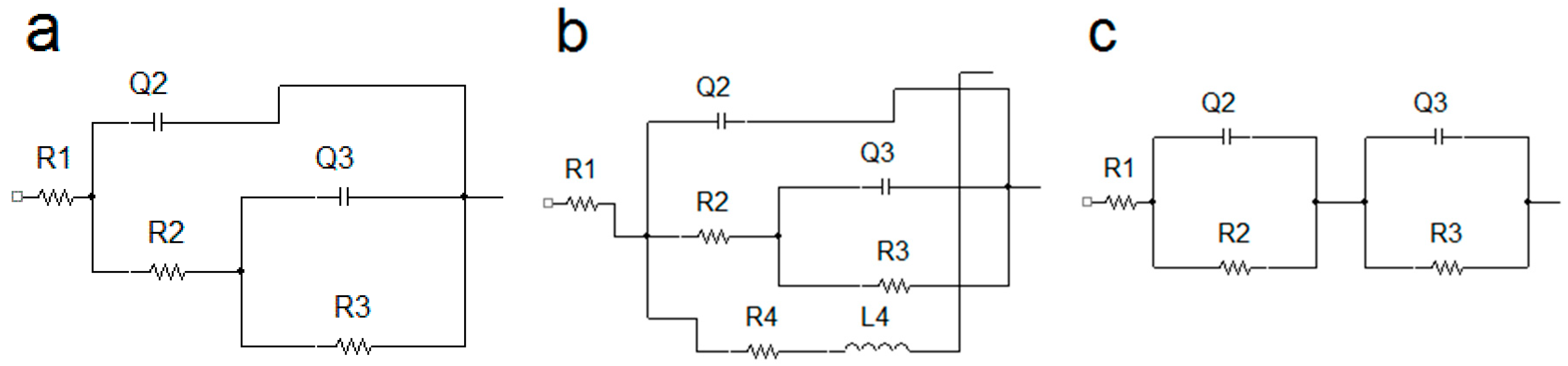
3.5. Electrochemical Impedance Spectroscopy Characteristics

Measured Nyquist plots obtained for the AZ91 magnesium alloy and Ni-P coatings on AZ91 alloy characterizing the long-time electrochemical corrosion behavior of the material in 0.1 M NaCl solution are shown in Figure 5 and Figure 6. Figure 5 shows the Nyquist plots of AZ91 magnesium alloy during 168 h of exposition. Figure 6 shows the Nyquist plots of AZ91 alloy with deposited duplex Ni-P coatings. In the case of 25 and 50 µm thick coatings, corrosion attack and local destruction of Ni-P coating were observed (Figure 6b,d), while in the case of 75 and 100 µm thick coatings no visible corrosion attack after 168 h (Figure 6f,h) was detected.
As seen in Nyquist plots, corresponding to the uncoated AZ91 alloy (Figure 5a), the increase in polarization resistance Rp was observed from the start of the experiment up to 8 h of the exposition. The decrease in Rp was observed at 8 h of exposition, where the value of Rp dropped from 9880 Ω·cm2 (8 h) to 3685 Ω·cm2 (12 h) (Table 4). This phenomenon is associated with the fact that the thin layer of Mg(OH)2 has been created on the specimen surface at the beginning of the exposition. The formed layer grew with the exposure time. However, this layer is chemically unstable in water solutions and in solutions containing Cl ions [3,30]. This passive layer broke down between 4 and 8 h of exposition, resulting in uncovering of the metallic substrate surface. The uncovered substrate immediately reacted with the corrosive media to form Mg(OH)2 and fill the defects in damaged layer [30]. This formation of the passive layer led to the following increase in Rp up to 72 h of exposition when the phenomenon was repeated. Figure 5b shows that a pitting occurred during the exposition in 0.1 M NaCl solution, which can be reflected in the inductive response of Nyquist plots (Figure 5a). The pitting is typical for the magnesium alloys [3,21,35]. The behavior is the consequence of different potential of Mg solid solution and of present intermetallic phase particles and eutectics, creating a galvanic couple [3,22].
The EIS plots for 25 and 50 µm thick coatings are shown in Figure 6a,c, correspondingly. The values of polarization resistance Rp increased with increased exposition time in NaCl solution up to 96 h. This increase in Rp is probably observed due to the reaction between Ni and corrosive environment, which led to the formation of passive film on the surface of the Ni-P coating. This film could provide a barrier against the corrosion attack on Ni-P coating and thus protect the coated AZ91 alloy. Nickel undergoes the passivation reaction in aqueous solutions forming several nanometers thick film of nickel oxide (NiO) or hydrated nickel oxide (NiOxHy) [36,37].
The corrosion attack on 25 µm thick duplex coating occurred in the interval from 96 to 168 h of exposition, where the destruction of Ni-P coating and the corrosion of AZ91 alloy occurred (Figure 6b). In the case of 25 µm thick coatings, the polarization resistance at 168th hr decreased from 233 570 Ω·cm2 (96 h) to 63 Ω·cm2 (168 h). This value is substantially lower when compared to the uncoated magnesium alloy. The drop can be explained by the galvanic coupling between Mg alloy and Ni-P coating [30]. Because the Ni-P coating was destroyed and the corrosive environment reacted with the substrate, the corrosion of the substrate was accelerated. The reaction was accompanied by the hydrogen evolution due to the reaction of Mg and corrosive solution.
In the case of 50 µm thick duplex Ni-P coating, formation of blisters (Figure 6d) during the measurement was observed. Since no damage of the coating was observed, no significant change in polarization resistance was observed during the measurement, and the value of Rp remained almost unchanged from 46 to 168 h of measurement.
Figure 6f shows 75 µm thick duplex Ni-P coating on the AZ91 alloy. It is obvious that the deposited coating was not completely homogenous before the NaCl exposition; it was rough, and visible protrusions could be observed. As presented in [2,38], these protrusions contain higher amount of structural defects [39]. Clearly, the corrosive solution can easily pass through these defects to the magnesium substrate, or it can be detained in pores of these protrusions. This phenomenon is then reflected in the value of polarization resistance Rp (Figure 6e). Due to the corrosion of the substrate as a consequence of the detained solution in the pores of Ni-P coating and structural defects, the passivation layer of NiO is disturbed or removed, resulting in the revelation of Ni-P coating.
In the case of 100 µm thick duplex Ni-P coating, no defects or blisters were observed (Figure 6h) on the sample surface after the measurement. Similar values of the polarization resistance in time determined for the samples are consistent with this observation.
To describe the electrochemical corrosion behavior of uncoated AZ91 alloy and AZ91 alloy with deposited Ni-P coatings in 0.1 M NaCl, the equivalent circuits (EC) simulating solution/sample interface given in Figure 7 were used. Figure 7a shows the EC model including two capacitive loops for high and low frequencies formed by capacities (Q) and their resistances (R); R1 (resistance of the solution), R2 (resistance of Mg(OH)2/NaCl solution interface) and R3 (resistance of metallic Mg and NaCl solution interface) [40]. This model describes the behavior of uncoated AZ91 alloy exhibited in 0.1 M NaCl solution for 5 min. The model corresponds to the formation of a thin layer of Mg(OH)2 on the metallic surface of AZ91 alloy [31]. However, formed Mg(OH)2 layer is not completely uniform due to its porous nature and is also damaged by cracks, and so the metallic surface of AZ91 alloy was in contact with the corrosive environment [3,21]. The resulting Rp value is the sum of R2 and R3 according to Equation (5).
R P = R 2 + R 3
The EC model (Figure 7b) representing the electrochemical corrosion behavior of uncoated AZ91 alloy in 0.1 M NaCl solution after 5 min includes the elements such as R1, which is the solution resistance [41]. High-frequency loop characterizing damaged Mg(OH)2 layer is observed—elements Q2 and R2 (Figure 7b). Low-frequency loop describing the interface of the solution and revealed metallic substrate (defects in the protecting layer of corrosion products) is defined by elements Q3 and R3. Inductive loop characterized by elements L4 (inductance) and R4 is related to the description of negative difference effect (NDE) caused by the adsorption of ions (H+, Mg+ or Cl) on the sample surface and evolution of gas H2 [3,42]. The resulting Rp value is calculated according to Equation (6).
R P = ( R 2 + R 3 ) R 4 R 2 + R 3 + R 4
The exposed sample of uncoated AZ91 alloy was heavily corroded, and the pitting was visible on the surface (Figure 5b) after 168 h in 0.1 M NaCl solution. During 168 h, the NDE effect and the adsorption of ions do not play such a big role as within 1–96 h; therefore, the EC model given in Figure 7a was used for the analysis of measured data again.
The behavior of the magnesium alloy in the corrosive environment was characterized by the creation of porous layer of Mg(OH)2. Only a low corrosion protection was provided by the formation of layer of corrosion products on the magnesium alloy surface. However, this porous layer did not protect the magnesium alloy against the corrosive medium sufficiently, and the corrosion process occurred. As a result, the lowest values of the polarization resistance were determined for untreated specimens when compared to coated samples, Table 4.
The behavior of all duplex Ni-P coatings deposited on the AZ91 magnesium alloy samples was analyzed by the EC model in Figure 7c, except the 25 µm coating after 168 h of the exposure to the corrosive environment [43]. In the case of the EC model shown in Figure 7c, R1 is the resistance of the solution, R2 is the resistance against the charge transfer between the electrolyte (NaCl solution) and upper high-phosphorus layer of the Ni-P coating, Q2 is the capacity of double-layer NaCl solution/ Ni-P coating, R3 is the resistance against the charge transfer between high-phosphorus and low-phosphorus layers of the Ni-P coating, and Q3 is the corresponding capacity. The resulting polarization resistance value is given by Equation (5) [31].
The EC model in Figure 7b was used for the analysis of the Nyquist plot for 25 µm thick Ni-P coating on the AZ91 alloy after 168 h in 0.1 M NaCl solution. The resulting polarization resistance value is given by the relation in Equation (6) [31].
The values of polarization resistance determined for the samples with 25, 50 and 100 µm thick coatings were comparable to each other, see Table 4, so it can be assumed that all layers offered the same protection against corrosion regardless of the coating thickness.

3.6. Corrosion Behavior during Immersion Tests

From the results of long-term immersion tests in 10% HCl and 3.5% NaCl solutions at room temperature, it can be seen that the corrosion resistance of coated samples increased with increasing thickness of deposited duplex Ni-P coatings (Table 5). For 100 μm thick duplex Ni-P coating no hydrogen bubble arising from the surface was observed in 10% HCl solution up to 24 h. For the sample with 100 μm thick coating immersed into 3.5% NaCl solution hydrogen bubble was observed for 792 h.
The corrosion model describing the damage of Ni-P coating deposited on magnesium alloy is referred to in the article [2]. Hydrogen evolves during the deposition of Ni-P coating (Equations (7) and (8)) as a byproduct of the reaction, and produced hydrogen is adsorbed on the surface of growing coating. This phenomenon results in the formation of pores or channels in the coating through which the corrosive medium can potentially pass to the magnesium substrate [7,44,45].
Ni 2 + + 4 H 2 PO 2 - + H 2 O Ni 0 + 3 H 2 PO 3 - + P 0 + H 2 ( ads ) + H +   H +
2 H H 2
When the coated magnesium-based substrate is immersed into the solution containing Cl ions, the solution can penetrate to the magnesium substrate surface through the defects in the coating. As a result, the corrosion cells are formed on the coated surface because the Ni-P coating acts as a cathode, and magnesium substrate acts as an anode and corrodes [37].
The improvement of corrosion properties of the substrate was achieved by the deposition of ternary Ni-P coatings. Zhang et al. [14] referred that deposited Ni-Sn-P coatings can increase the corrosion resistance of magnesium alloy in 10% HCl solution several times when compared to binary Ni-P coatings. For 35 µm thick Ni-Sn-P ternary coating deposited on the AZ91D magnesium alloy, no hydrogen bubbles arising from the surface after the immersion in 10% HCl solution for 608 min were observed. Meanwhile, the Ni-P coating with the same thickness protected the substrate only for 76 min (1.27 h). Zhang et al. [16] also stated that deposited 24 µm thick ternary Ni-W-P coating protected the substrate in 10% HCl solution for 187 min (3.12 h) without observing any hydrogen bubbles arising from the coated specimen surface. The Ni-P coating with the thickness of 28 µm protected the material only for 45 min (0.75 h).
The corrosion resistance (exposition time) of all analyzed deposited duplex Ni-P coatings in 10% NaOH solution reached 1000 h (Table 5). Zeller a Salvati [37] reported that very low corrosion rates (≤ 2 μm/py) were measured for the Ni-P coatings in 50% NaOH solution at room temperature. The authors also concluded that the corrosion resistance of coated substrate in the NaOH solution is dependent upon the content of P in deposited Ni-P coatings. High-phosphorus Ni-P coatings have worse corrosion resistance in comparison with medium or low-phosphorus coatings. Low-phosphorus coatings have the corrosion resistance comparable to pure nickel. The explanation is that phosphorus present in the Ni-P coating may form soluble complexes of nickel (Ni3[PO4]2) on the coating surface in water. As a result, nickel forming the passive Ni(OH)2/NiO film is removed from coated substrate surface. The thickness of surface protective Ni(OH)2/NiO film is dependent on the P content [37,46].
Even though the top layer of experimental duplex coatings was formed by high-phosphorus coating and a low protection against the corrosion could be assumed, the exposition time of coated AZ91 specimens reached 1000 h. A good corrosion resistance could be reached due to quite high thickness of the layer and due to the formation of nickel oxide (NiO) or hydrated nickel oxide (NiOxHy) on the surface, protecting the material against the corrosion [37].

3.7. Neutral Salt Spray Exposure

According to the immersion tests, the exposition time in NSS increased with the increasing thickness of the duplex Ni-P coatings as well as for 10% HCl and 3.5% NaOH solutions (Table 5). Higher coating thickness increased the resistance of alloy against the corrosion. The individual for each coating are listed in Table 5.
The presence of pits on the Ni-P coating nodules boundaries is documented in Figure 8a. This phenomenon was observed for all coatings and was caused by the corrosion attack on the sample in the salt spray. The EDS analysis (Figure 8b) showed higher oxygen content (9.4 wt.%), which can suggest the presence of porous passive Ni(OH)2/NiO thin layer [37].
The mechanism of the corrosion attack on the Ni-P coated AZ91 alloy was the same as for the immersion tests. The micropores present in the Ni-P coating allow the transport of the corrosion media into the magnesium alloy surface. As a consequence, the magnesium alloy corrosion and hydrogen evolution proceed resulting in the coating damage. The following corrosion is even accelerated due to the magnesium alloy revealing to the corrosion environment. This mechanism was observed also in [47] and [48].

4. Conclusions

The study of the corrosion resistance of duplex Ni-P coating deposited on AZ91 magnesium alloy was performed in various environments. Based on the experimental results, the following conclusions can be drawn:
  • Ni-P coatings with final thicknesses of 25, 50, 75 and 100 µm deposited on AZ91 magnesium alloy were formed by two layers—inner low-phosphorus Ni-P layer with the average P content of 5.7 wt.% and outer high-phosphorus Ni-P layer with the average P content of 11.5 wt.%.
  • Low-phosphorus inner layer has the average microhardness of 620 ± 20 HV 0.025, and the outer high-phosphorus top layer has the average microhardness of 580 ± 10 HV 0.025.
  • Deposited coatings significantly improved the corrosion resistance of the AZ91 magnesium alloy.
  • Potentiodynamic tests in 0.1 M NaCl solution showed that the Ni-P duplex coatings deposited on AZ91 alloy improved the alloy electrochemical corrosion properties; a significant shift of Ecorr from −1563 mV to ~−430 mV was observed. The value of icorr decreased from 6.289 µA·cm−2 to 0.358 µA·cm−2. All coatings exhibited similar electrochemical characteristics, regardless of the coating thickness.
  • From the results of long-term EIS measurements, the highest value of Rp = 250 167 Ω·cm2 in 0.1 M NaCl solution after 168 h for 100 µm thick coating was determined. All layers offered the same protection against the corrosion regardless of the coating thickness, except the coating with the thickness of 75 µm reaching slightly lower values of the polarization resistance.
  • The immersion tests in 3.5% NaCl solution and 10% HCl solution and salt spray tests showed that with increasing thickness of the duplex Ni-P coating, the exposition time characterizing the resistance of specimens against the corrosion was increasing. In the case of the immersion test in 10% NaOH, the exposition time reached up to 1000 h for all coated samples.

Author Contributions

Conceptualization, J.W.; methodology, J.T., J.M. and L.D.; validation, J.W. and S.F.; formal analysis, M.B.; investigation, M.B.; resources, J.W.; writing—original draft preparation, M.B.; writing—review and editing, J.W., S.F. and L.D. All authors have read and agreed to publish the version of the manuscript.

Acknowledgments

This work was supported by project Nr. LO1211, Materials Research Centre at FCH BUT–Sustainability and Development (National Programme for Sustainability I, Ministry of Education, Youth and Sports).

Conflicts of Interest

The authors declare no conflict of interest.

References

  1. Friedrich, H.; Mordike, B.L. Magnesium Technology: Metallurgy, Design Data, Applications; Springer: New York, NY, USA, 2006; ISSN 978-3-540-20599-9. [Google Scholar]
  2. Buchtík, M.; Kosár, P.; Wasserbauer, J.; Tkacz, J.; Dolezal, P. Characterization of Electroless Ni–P Coating Prepared on a Wrought ZE10 Magnesium Alloy. Coatings 2018, 8, 96. [Google Scholar] [CrossRef] [Green Version]
  3. Liu, H.; Cao, F.; Song, G.-L.; Zheng, D.; Shi, Z.; Dargusch, M.; Atrens, A. Review of the atmospheric corrosion of magnesium alloys. J. Mater. Sci. Technol. 2019, 35, 2003–2016. [Google Scholar] [CrossRef]
  4. Gupta, M.; Nai, M.L.S. Magnesium, Magnesium Alloys, and Magnesium Composites; John Wiley: New York, NY, USA, 2011; ISSN 978-0-470-49417-2. [Google Scholar]
  5. Song, G.-L. Corrosion Prevention of Magnesium Alloys; Elsevier BV: Oxford, UK; Cambridge, UK; Philadelphia, PA, USA; New Delhi, India, 2013; p. 978. [Google Scholar]
  6. Anthony, E.H.; Johannes, M.C.M.; Mikhail, L.Z.; Rudolph, G.B. Active Protective Coatings; Springer: New York, NY, USA, 2016; ISSN 978-9401775380. [Google Scholar]
  7. Riedel, W. Electroless Nickel Plating; Reprinted; ASM International: Cleveland, OH, USA, 1991; p. 320. ISSN 9780904477122. [Google Scholar]
  8. Parkinson, R. Properties and Applications of Electroless Nickel; Nickel Development Institute: Toronto, ON, Canada, 1997. [Google Scholar]
  9. Mallory, G.O.; Hajdu, J.B. Electroless Coating: Fundamentals and Applications; Knoyes Publishing: William Andrew, UK, 2009; p. 575. [Google Scholar]
  10. Sudagar, J.; Lian, J.; Sha, W. Electroless nickel, alloy, composite and nano coatings—A critical review. J. Alloys Compd. 2013, 571, 183–204. [Google Scholar] [CrossRef] [Green Version]
  11. Agarwala, R.C.; Agarwala, V. Electroless alloy/composite coatings: A review. Sadhana 2003, 28, 475–493. [Google Scholar] [CrossRef]
  12. Lo, P.-H.; Tsai, W.-T.; Lee, J.-T.; Hung, M.-P. Role of phosphorus in the electrochemical behavior of electroless Ni-P alloys in 3.5 wt.% NaCl solutions. Surf. Coat. Technol. 1994, 67, 27–34. [Google Scholar] [CrossRef]
  13. Gu, C.; Lian, J.; Li, G.; Niu, L.; Jiang, Z. High corrosion-resistant Ni–P/Ni/Ni–P multilayer coatings on steel. Surf. Coat. Technol. 2005, 197, 61–67. [Google Scholar] [CrossRef]
  14. Zhang, W.; Jiang, Z.; Li, G.; Jiang, Q.; Li, G. Electroless Ni–Sn–P coating on AZ91D magnesium alloy and its corrosion resistance. Surf. Coat. Technol. 2008, 202, 2570–2576. [Google Scholar] [CrossRef]
  15. Zhang, W.; Jiang, Z.; Li, G.; Jiang, Q.; Li, G. Electroless Ni-P/Ni-B duplex coatings for improving the hardness and the corrosion resistance of AZ91D magnesium alloy. Appl. Surf. Sci. 2008, 254, 4949–4955. [Google Scholar] [CrossRef]
  16. Zhang, W.; Huang, N.; He, J.; Jiang, Z.; Jiang, Q.; Li, G. Electroless deposition of Ni–W–P coating on AZ91D magnesium alloy. Appl. Surf. Sci. 2007, 253, 5116–5121. [Google Scholar] [CrossRef]
  17. Zhang, J. Corrosion Behavior of Electroless Ni-P/Ni-B Coating on Magnesium Alloy AZ91D in NaCl Environment. Int. J. Electrochem. Sci. 2016, 11, 10053–10066. [Google Scholar] [CrossRef]
  18. Czerwinski, F. Magnesium Alloys: Design, Processing and Properties; InTech: Rijeka, Croatia, 2011; ISBN 978-953-307-520-4. [Google Scholar]
  19. Sun, C.; Guo, X.; Wang, S.-H.; Guo, J.-C.; Ding, W. Homogenization pretreatment and electroless Ni–P plating on AZ91D magnesium alloy. Trans. Nonferrous Met. Soc. China 2014, 24, 3825–3833. [Google Scholar] [CrossRef]
  20. Zhang, W.; He, J.; Jiang, Z.; Jiang, Q.; Li, G. Electroless Ni–P layer with a chromium-free pretreatment on AZ91D magnesium alloy. Surf. Coat. Technol. 2007, 201, 4594–4600. [Google Scholar] [CrossRef]
  21. Tkacz, J.; Slouková, K.; Minda, J.; Drábiková, J.; Fintová, S.; Dolezal, P.; Wasserbauer, J. Influence of the Composition of the Hank’s Balanced Salt Solution on the Corrosion Behavior of AZ31 and AZ61 Magnesium Alloys. Metals 2017, 7, 465. [Google Scholar] [CrossRef] [Green Version]
  22. Ambat, R.; Zhou, W. Electroless nickel-plating on AZ91D magnesium alloy: Effect of substrate microstructure and plating parameters. Surf. Coat. Technol. 2004, 179, 124–134. [Google Scholar] [CrossRef]
  23. Zarebidaki, A.; Mahmoudikohani, H.; Aboutalebi, M.-R. Microstructure and corrosion behavior of electrodeposited nano-crystalline nickel coating on AZ91 Mg alloy. J. Alloy. Compd. 2014, 615, 825–830. [Google Scholar] [CrossRef]
  24. Wang, H.-L.; Liu, L.-Y.; Dou, Y.; Zhang, W.-Z.; Jiang, W.-F. Preparation and corrosion resistance of electroless Ni-P/SiC functionally gradient coatings on AZ91D magnesium alloy. Appl. Surf. Sci. 2013, 286, 319–327. [Google Scholar] [CrossRef]
  25. Shu, X.; Wang, Y.; Liu, C.; Aljaafari, A.; Gao, W. Double-layered Ni-P/Ni-P-ZrO 2 electroless coatings on AZ31 magnesium alloy with improved corrosion resistance. Surf. Coat. Technol. 2015, 261, 161–166. [Google Scholar] [CrossRef]
  26. Duncan, R.N. The metallurgical structure of electroless nickel deposits: Effect on coating properties. Plat. Surface Finish. 1996, 8, 65–69. [Google Scholar]
  27. Mainier, F.B.; Fonseca, M.P.C.; Tavares, S.S.M.; Pardal, J.M. Quality of Electroless Ni-P (Nickel-Phosphorus) Coatings Applied in Oil Production Equipment with Salinity. J. Mater. Sci. Chem. Eng. 2013, 1, 1–8. [Google Scholar]
  28. Sampath, K.P.; Kesavan, N.P. Studies on crystallization of electroless Ni-P deposits. J. Mater. Process. Technol. 1996, 56, 511–520. [Google Scholar] [CrossRef]
  29. Czagany, M.; Baumli, P. Effect of pH on the characteristics of electroless Ni-P coatings. J. Min. Met. Sect. B Met. 2017, 53, 327–332. [Google Scholar] [CrossRef] [Green Version]
  30. Song, G.L.; Atrens, A. Corrosion Mechanisms of Magnesium Alloys. Adv. Eng. Mater. 1999, 1, 11–33. [Google Scholar] [CrossRef]
  31. Březina, M.; Minda, J.; Dolezal, P.; Krystýnová, M.; Fintová, S.; Zapletal, J.; Wasserbauer, J.; Ptáček, P. Characterization of Powder Metallurgy Processed Pure Magnesium Materials for Biomedical Applications. Metals 2017, 7, 461. [Google Scholar] [CrossRef] [Green Version]
  32. Lampke, T.; Leopold, A.; Dietrich, D.; Alisch, G.; Wielage, B. Correlation between structure and corrosion behaviour of nickel dispersion coatings containing ceramic particles of different sizes. Surf. Coat. Technol. 2006, 201, 3510–3517. [Google Scholar] [CrossRef]
  33. Fini, M.H.; Amadeh, A. Improvement of wear and corrosion resistance of AZ91 magnesium alloy by applying Ni–SiC nanocomposite coating via pulse electrodeposition. Trans. Nonferrous Met. Soc. China 2013, 23, 2914–2922. [Google Scholar] [CrossRef]
  34. Alishahi, M.; Monirvaghefi, S.M.; Saatchi, A.; Hosseini, S. The effect of carbon nanotubes on the corrosion and tribological behavior of electroless Ni–P–CNT composite coating. Appl. Surf. Sci. 2012, 258, 2439–2446. [Google Scholar] [CrossRef]
  35. Zeng, R.; Zhang, J.; Huang, W.; Dietzel, W.; Kainer, K.; Blawert, C.; Ke, W. Review of studies on corrosion of magnesium alloys. Trans. Nonferrous Met. Soc. China 2006, 16, s763–s771. [Google Scholar] [CrossRef]
  36. Orel, Z.C.; Hutchins, M.; Mcmeeking, G. The electrochromic properties of hydrated nickel oxide films formed by colloidal and anodic deposition. Sol. Energy Mater. Sol. Cells 1993, 30, 327–337. [Google Scholar] [CrossRef]
  37. Zeller, R.L.; Salvati, L. Effects of Phosphorus on Corrosion Resistance of Electroless Nickel in 50% Sodium Hydroxide. Corrosion 1994, 50, 457–467. [Google Scholar] [CrossRef]
  38. Chen, B.-H.; Hong, L.; Ma, Y.; Ko, T.-M. Effects of Surfactants in an Electroless Nickel-Plating Bath on the Properties of Ni−P Alloy Deposits. Ind. Eng. Chem. Res. 2002, 41, 2668–2678. [Google Scholar] [CrossRef]
  39. Balaraju, J.; Narayanan, T.S.; Seshadri, S. Electroless Ni–P composite coatings. J. Appl. Electrochem. 2003, 33, 807–816. [Google Scholar] [CrossRef]
  40. Fan, L.; Tang, F.; Reis, S.T.; Chen, G.; Koenigstein, M.L. Corrosion Resistances of Steel Pipes Internally Coated with Enamel. Corrosion 2017, 73, 1335–1345. [Google Scholar] [CrossRef]
  41. Fu, Z.; Chen, X.; Liu, B.; Liu, J.; Han, X.; Deng, Y.; Hu, W.; Zhong, C. One-Step Fabrication and Localized Electrochemical Characterization of Continuous Al-Alloyed Intermetallic Surface Layer on Magnesium Alloy. Coatings 2018, 8, 148. [Google Scholar] [CrossRef] [Green Version]
  42. Song, G.-L.; Atrens, A.; Wu, X.; Zhang, B. Corrosion behaviour of AZ21, AZ501 and AZ91 in sodium chloride. Corros. Sci. 1998, 40, 1769–1791. [Google Scholar] [CrossRef]
  43. Fan, L.; Reis, S.T.; Chen, G.; Koenigstein, M. Corrosion Resistance of Pipeline Steel with Damaged Enamel Coating and Cathodic Protection. Coatings 2018, 8, 185. [Google Scholar] [CrossRef] [Green Version]
  44. Song, Y.; Shan, D.; Han, E.-H. High corrosion resistance of electroless composite plating coatings on AZ91D magnesium alloys. Electrochim. Acta 2008, 53, 2135–2143. [Google Scholar] [CrossRef]
  45. Chen, M.-A.; Cheng, N.; Li, J.-M.; Liu, S. Improvement to corrosion resistance of Ni–P coating on MAO magnesium alloy by BTESPT. Surf. Eng. 2012, 28, 491–497. [Google Scholar] [CrossRef]
  46. Moore, R.L.; Salvati, J.L. Investigation of the correlation between surface properties and surface chemistry of electroless nickel coatings. Thin Solid Films. 1990, 193, 1–574. [Google Scholar] [CrossRef]
  47. Liao, Y.; Zhang, S.T.; Dryfe, R. A study of corrosion performance of electroless Ni-P and Ni-W-P coatings on AZ91D magnesium alloy. Mater. Werkst. 2011, 42, 833–837. [Google Scholar] [CrossRef]
  48. Wang, L.L.; Chen, H.J.; Hao, L.; Lin, A.; Gan, F.X. Electrochemical corrosion behavior of electroless Ni-P coating in NaCl and H2SO4 solutions. Mater. Corros. 2010, 62, 1003–1007. [Google Scholar] [CrossRef]
Figure 1. Morphology and structure of the AZ91 surface. (a) after grinding and degreasing, (b) after activation; SEM.
Materials 13 01357 g001
Figure 2. Surface morphology of Ni-P coating. (a) low-phosphorus interlayer, (b) high-phosphorus top coating; coating thickness 25 µm.
Materials 13 01357 g002
Figure 3. Micrograph (a) and EDS maps of deposited Ni-P coating on the AZ91 alloy: (b) Ni, (c) P, (d) Mg and (e) Al.
Materials 13 01357 g003aMaterials 13 01357 g003b
Figure 4. Typical potentiodynamic curves of AZ91 alloy and Ni-P coatings on AZ91 magnesium alloy in 0.1 M NaCl.
Materials 13 01357 g004
Figure 5. Nyquist plots of AZ91 magnesium alloy during measurement at different immersion times from 5 min until 168 h in 3.5 wt.% NaCl. (a) EIS of the uncoated AZ91 alloy and (b) sample of the uncoated AZ91 alloy after 168 h of exposition.
Materials 13 01357 g005
Figure 6. Nyquist plots of Ni-P coatings on AZ91 alloy during measurement at different immersion time from 5 min until 168 h in 3.5 wt.% NaCl. (a) EIS 25 µm, (b) sample 25 µm, (c) EIS 50 µm, (d) sample 50 µm, (e) EIS 75 µm, (f) sample 75 µm, (g) EIS 100 µm and (h) sample 100 µm.
Materials 13 01357 g006aMaterials 13 01357 g006b
Figure 7. Equivalent electrical circuit models used for the EIS data analysis. (a) EC for the analysis of uncoated AZ91 alloy, (b) EC for the analysis of 25 µm thick Ni-P coating on the AZ91 alloy after 168 h and (c) EC for the analysis of all duplex Ni-P coatings.
Materials 13 01357 g007
Figure 8. Example of the surface morphology of duplex Ni-P coating (100 µm) after the exposition in NSS for 430 h (a) and the surface EDS analysis (b).
Materials 13 01357 g008
Table 1. Elemental composition of AZ91 magnesium alloy [wt.%].
AlZnMnSiFeNiZrMg
Content8.800.810.320.01<0.01<0.010.01Balance
Table 2. AZ91 magnesium alloy pre-treatment and coating conditions.
ProcessParametersConditions
GrindingSiC paperNo. 1200
Alkaline degreasingSoil releasing agentspH < 12, higher temp., 20 min
Acid picklingAcid bath25 °C, 5 s
Low-phosphorus electroless nickel bathNiSO4·6H2O
NaH2PO2·H2O
complexing agent
activator
1.5/2 h (14/18 µm)
60 °C
pH 6.8 ± 0.1
High-phosphorus electroless nickel bathIndustrial NiChem HP 1151 (Atotech)1.5/3/5.5/8.5 h
90 °C
pH 4.7 ± 0.1
Table 3. Corrosion potential and corrosion current density of Ni-P coatings determined from potentiodynamic curves.
Thickness of Ni-P Coating [µm]Ecorr [mV]icorr [µA·cm−2]
AZ91 alloy−15636.289
25−4250.358
50−4340.371
75−4310.365
100−4100.457
Table 4. Values of polarization resistance of plain AZ91 magnesium alloy and deposited Ni-P coatings in 0.1 M NaCl solution.
SamplesRp [ Ω·cm2]
5 Minutes1 Hour2 Hours4 Hours8 Hours12 Hours
AZ91 alloy120731672588215298803685
Ni-P 25 µm47,78785,110101,11286,969114,169134,782
Ni-P 50 µm36,73070,72380,35688,790118,200131,146
Ni-P 75 µm18,69426,68826,59124,79422,21231,847
Ni-P 100 µm20,13638,92050,20367,388115,983138,065
SamplesRp [ Ω·cm2]
24 Hours48 Hours72 Hours96 Hours168 Hours
AZ91 alloy5,7865,5439,0111,29411,342
Ni-P 25 µm164,038181,489190,141233,57063
Ni-P 50 µm120,846201,011214,179264,982218,359
Ni-P 75 µm42,01655,87357,29459,39172,095
Ni-P 100 µm199,510159,432173,856242,660250,167
Table 5. Exposition times in selected environments [hours].
Thickness of Duplex Ni-P Coating [µm]Environment
10% HCl Solution3.5% NaCl Solution10% NaOH SolutionExposition Time NSS
252264100096
5054081000149
75115521000332
100247921000430

