Abstract
The propensity to manufacture functional and geometrically sophisticated parts from a wide range of metals provides the metal additive manufacturing (AM) processes superior advantages over traditional methods. The field of metal AM is currently dominated by beam-based technologies such as selective laser sintering (SLM) or electron beam melting (EBM) which have some limitations such as high production cost, residual stress and anisotropic mechanical properties induced by melting of metal powders followed by rapid solidification. So, there exist a significant gap between industrial production requirements and the qualities offered by well-established beam-based AM technologies. Therefore, beamless metal AM techniques (known as non-beam metal AM) have gained increasing attention in recent years as they have been found to be able to fill the gap and bring new possibilities. There exist a number of beamless processes with distinctively various characteristics that are either under development or already available on the market. Since this is a very promising field and there is currently no high-quality review on this topic yet, this paper aims to review the key beamless processes and their latest developments.
1. Introduction
There has been a trend in metal additive manufacturing (AM) in recent years and much of the reports on AM are about the growth in metal-AM and its significant impact on design and rapid manufacture of geometrically complicated high-end parts. A recent Wohlers Report [1] demonstrates a significant growth in the metal-AM market so that an estimated 1768 metal-AM systems were sold in 2017, compared to 983 systems in 2016, an increase of approximately 80%. The main benefits of metal-AM in comparison with conventional manufacturing are a shorter value chain, reduced production cost and lead times for intricate parts, greater design freedom and customization, and minimal waste of materials.
The current highlights of metal AM are divided into two main categories: beam-based and beamless techniques (Figure 1). As classified by American Society for Testing and Materials (ASTM), powder bed fusion (PBF) and directed energy deposition (DED) methods represent the key beam-based approaches for fabricating metals and alloys [2]. Comprehensive reviews of the beam-based metal-AM systems have been presented in [3,4,5,6]. EBM and SLM, the main representative of the PBF method, are currently dominant metal-AM processes because of the superior mechanical properties of the printed highly demanding functional parts. In these beam-based techniques, the powder/beam interactions result in sophisticated physical phenomena including: melting, dynamic melt flow, and rapid solidification that results in highly orientated, columnar grains with anisotropic mechanical properties [3]. The high thermal stress and rapid solidification can also lead to detrimental residual stress and defects such as delamination and severe part distortion. In addition, the beam-based metal-AM systems are energy inefficient, and suffer from the high costs of technology and operations as well as constraints on speed, precision and surface quality. Moreover, it is quite challenging to process non-weldable metals through beam-based metal-AM systems [7,8].
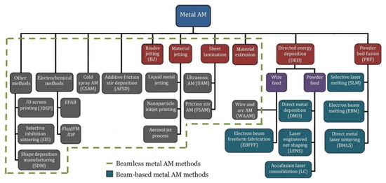
Figure 1.
Classification of the main current metal AM processes, including beam-based and beamless techniques.
Beamless metal AM techniques (known as non-beam metal AM) are being employed effectively to overcome the above limitations of the beam-based systems. There exist a number of beamless processes with various distinct characteristics that are either under development or already available in the market. These approaches provide different opportunities in terms of process economics, mechanical properties, achievable geometries and surface quality.
Beamless metal AM has been able to draw the attention of both the research community and industry. The growth in beamless research over the past five years is reflected in the number of publications [9]. In addition to the research community, there has been a significant growth in the beamless metal AM market as presented in Figure 2.
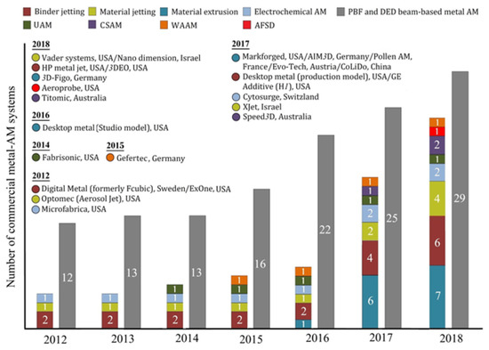
Figure 2.
Growth in beamless metal-AM systems comparing with beam-based systems (column numbers indicate the number of most common commercially launched systems), data acquired from the Scopus database, and the Wohlers Report [1].
As seen in Table 1, the beamless systems are additive processes in which material bonding within and between layers occurs without using laser/electron beam melting. Liquid metal jetting (a type of material jetting technology), wire and arc AM (WAAM), and shape deposition manufacturing (SDM) approaches are based on material melting, similar to beam-based techniques. However, they use energy sources other than laser or electron beam for melting of materials. Some of the beamless methods including binder jetting (known as 3D printing), material extrusion, nanoparticles inkjet printing, selective inhibition sintering (SIS), aerosol jet, and 3D screen printing use bulk sintering in the furnace for layer bonding. The extrusion-based systems can massively reduce production costs, while binder jetting can achieve higher print resolution and surface finish than the beam-based systems. More important, the printed metal parts using this class of metal AM systems possess remarkably lower residual thermal stress than beam-based systems since the green parts are sintered after printing.

Table 1.
Layer bonding mechanisms of different beamless metal AM techniques.
EFAB and FluidFM 3D printing technologies use electrochemical deposition methods that outperform the beam-based systems in terms of resolution and accuracy. Conversely, ultrasonic AM (UAM), additive friction stir deposition (AFSD), friction stir AM (FSAM), and cold spray AM (CSAM) processes use solid state thermo-mechanical bonding without the need for a protective print environment for printing mega scale parts which are not viable through beam-based systems [9]. UAM enables fast and scalable manufacturing for a wider range of engineering alloys, multiple materials and composites, and parts with embedded electronics due to its low operation temperature. CSAM has a very high deposition rate (almost 10 times faster than SLM) with no limitation in build size that makes this process well-suited for industrial scale production of near net shape large parts.
A comprehensive review of the key beamless metal AM systems and the current state of their research and technology are presented in this paper. The review outlines the principle of each beamless metal-AM processes followed by disseminating the efforts and recent progresses. Techniques that either have not been widely adopted (e.g., SDM and SIS) or their application field is mainly confined to writing (such as aerosol jet that needs laser beam for true 3D fabrication) are not addressed in this paper.
This review is based on Scopus and Google Scholar searches. Articles published over the period 2012–2019 have been selected and the full papers and other reviews have been analysed. Furthermore, Wohlers Report 2018 [1] and various internet sources have been used to analyse the market situation and future industrial trends in metal AM.
2. Key Processes
2.1. Material Jetting Processes
Material jetting which includes processes like liquid metal printing, nanoparticles inkjet printing or aerosol jet process (see Figure 1) is an AM process in which liquid droplets of build material are selectively deposited and become solid via cooling (e.g., by crystallization or vitrification), chemical changes (e.g., cross-linking of a polymer), or solvent evaporation [2,10,11]. Post-processing procedures such as sintering might be included to achieve near fully dense parts.
The material jetting process was initially used for printing parts out of wax [12] and polymers [13]. The material jetting process has also been widely used to print a variety of functional bio-constructs and tissues by patterning living cell-loaded materials and direct cell printing [14]. Orme et al. [15] and Yamaguchi et al. [16] first demonstrated 2.5D jetting of molten AA2024 aluminum (density 98.5%) and true 3D metal jetting of a molten fusible alloy (Bi-Pb-Sn-Cd-In alloy), respectively.
A number of research works have been conducted on droplet-based printing of low/medium stiffness metals such as Sn63-Pb37 alloys [17,18,19,20], aluminum [21,22,23], copper [24], tin, various solders [25] using nozzles typically between 50 to 200 μm in diameter.
Development of new jetting systems with higher print quality has been the main focus of recent research. In inkjet printing, the drop diameter normally ranges from one to two times that of the nozzle [26]. Droplets as small as around 60% [27] and 55% [28] of the nozzle diameter could be printed using a new pneumatic DOD and impact-driven ejection, respectively. To improve uniformity and accuracy of metal droplets, a pneumatically actuated inkjet printing system composed of a star-shaped nozzle was proposed for the generation of liquid metal microdroplets in the nano- to picoliter range [29,30]. High resolution pillars and microstructures with wall thickness of 25 µm could be printed using laser-induced forward transfer (LIFT) print heads that use laser beam to melt a thin metal layer for creating femtoliter droplets [31]. Electromagnetic print heads were also developed to eject uniform metal droplets at lower cost and higher speed [32]. The electromagnetism driven printing uses a piston that is accelerated by the magnet force to create droplets. Electrohydrodynamic printing technology (known as e-jet printing) was used by Han et al. [33] for high resolution printing of a double layer aluminum scaffold with uniform struts as fine as 100 µm. In e-jet, a high voltage is applied between a pneumatic-actuated nozzle and the ground electrode placed under the metal substrate to print molten metals at remarkably higher resolution than normal pneumatic jetting system.
The limited crucible volume is the main obstacle for further commercialization of liquid metal 3D printing. To overcome this problem, a wire-based feeding system was proposed by [34] for generation of continuous droplet stream of a low-melting-point alloy. The first liquid metal 3D printer was commercialized by Vader Systems under the trade name of “MagnetoJet” that uses a method very similar to that proposed several years ago by International Business Machines Corp (IBM, patent no. US5377961A). It uses magentohydrodynamic (MHD) actuation [35] integrated with a wire-based feeding system. Recently, Spiller and Fleischer [36] used a commercial ARBURG freeformer machine (originally developed for melt 3D printing using standard plastic granules) in the metal injection molding (MIM) process chain instead and proposed a new approach for droplet-based AM of sintered metal components. Their proposed ARBURG metal freeforming could reach properties very close to MIM; tensile strength: 95.7–99.2% of MIM produced metal parts.
Molten metal jetting is limited to low/medium melting temperature metals as for other metals a high-temperature resistant printing system is required to keep the metal molten during the jetting process [37]. XJet (Rehovot, Israel) has recently commercialized a low-temperature metal 3D printer that uses its proprietary NanoParticle Jetting™ (NPJ) technology. It prints nanoparticle inks of both build and support materials in ultrafine layers simultaneously. High temperature of the build chamber results in evaporation of the liquid content, leaving dense layers of materials with chemical composition similar to conventionally produced parts. The 3D printed green parts are then subjected to sintering process to achieve final dense metal parts, and support materials are easily removed.
2.2. Binder Jetting
Binder jetting (BJ), known as three-dimensional printing (3DP), was first developed at the Massachusetts Institute of Technology [38]. Binder jetting has demonstrated the capability of printing complex parts from a variety of materials, including ceramics [39], metals [40], shape-memory alloys (SMA) [41,42], polymers [43], polymer/ceramic [44] and drugs [45]. In the case of metallic powder, the printed green body is placed in a furnace to remove the binder and sinter the powder particles for densification. However, the final sintered parts possess relatively low density since powders are loosely deposited in the binder jet process. Therefore, other techniques such as infiltration (using a metal with lower melting point) and/or hot isostatic pressing (HIP) [46,47] are normally applied after sintering to enhance the density of the final part.
Binder jetting has been successfully used for printing of different metals such as stainless steel [48], titanium [49,50,51,52,53], biodegradable iron–manganese alloys [54], WC-CO hardmetals [55], superalloys [56,57,58], cobalt-chrome [59], magnetic materials [60,61,62], and high purity copper [63] that is challenging to process using beam-based AM technologies due to its optical reflectivity and high thermal conductivity.
Microstructural analysis and investigation of mechanical properties of the binder jetted metals has been a focal research topic [64,65]. Basically, the metal BJ process generates a relatively fine equiaxed grain microstructure, while the EBM and DMLS processes are conducive to comparable columnar grain microstructures as illustrated in Figure 3. Fatigue performance of the printed nickel-based superalloy 625 part could be improved by mechanical grinding of its surface, surpassing that of the cast alloy [66]. Steel Parts with tailored material gradients have been 3D printed using nanoparticle carbon black ink [67]. Sheydaeian and Toyserkani [68] developed a novel system for printing porous titanium parts by selective encapsulating of the sacrificial paraffin particles inside the powder layers during the binder jetting process. Porous biodegradable scaffolds have been binder jetted from Fe-Mn-Ca/Mg alloys with controlled in vitro degradation and cell attachment [69].
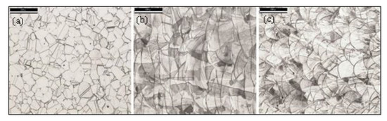
Figure 3.
Optical microscopy images of 316L samples in etched condition (Glyceregia etchant): (a) BJ 50× (b) EBM 50×; (c) DMLS 50×. Scale bars are 150 µm [70].
The main limitation of metal binder jetting is the relative density of metal parts (95–97%), which can be compared with a typical density of > 99% with laser-based powder bed systems. A number of research works have been conducted to investigate the effect of process parameters (such as layer thickness, binder saturation, drying after printing each layer) and part orientation [58,71], powder particle size and distribution [53,72,73,74], and post-processing [47] on density, and mechanical properties. The influence of layer thickness, powder particle size and sintering profiles in the binder jetting of IN718 superalloy was studies by Turker et al. [58]. Shrestha and Manogharan [75] used the Taguchi method to determine the optimum process parameters for improving transverse rupture strength of sintered SS 316L samples. Binder saturation level and feed-to-powder ratio were demonstrated as the most critical parameters, affecting binder/powder interaction and mechanical properties of the sintered parts. The use of bimodal powders has been demonstrated to be an effective approach to improve the packing density of powders, and thus surface finish [76] and final sintered density [77]. Kumar et al. [47] demonstrated that the use of HIP can improve the final copper part density from 92% (as-sintered) to 99.7% of theoretical density. HIP of powder bed fusion AM processes typically results in a strength drop due to a significant increase in the grain size. However, HIP improves the strength of BJ parts, which indicates that compared to grain coarsening, the improvement in porosity is the dominant factor in determining strength [47].
The selection of a binder material system determines green part strength and affects the sintered density and shrinkage [78]. Solvent-based polymeric binders are commonly used binders in commercial metal binder jetting systems. The use of the polymeric binders can add complexity and limitations to the sintering process and adversely affect the final mechanical properties. Functional inks containing metal nanoparticles have been proposed to replace polymeric binders with the aim of enhancing densification. Silver [79] and copper [80] parts printed using the nanoparticle ink were significantly enhanced in sintering quality than those printed using the polymeric binder system, in particular parts with thin or fine features with high aspect ratios. Particle-free metal salts with and without polymer binder were proposed [81] as an alternative approach due to difficulties in preparation and ink jetting of metal nanoparticle inks such as printhead clogging, particle sedimentation, and surface oxidation of nanoparticles during storage. Various existing inorganic metal salt solutions (e.g., copper nitrate hydroxide and copper sulfate) can be jetted, and convert to metal particles upon deposition via decomposition [81].
2.3. Material Extrusion
Material extrusion refers to the AM techniques that use an extrusion method for dispensing build material selectively. The process known under the trademarked name Fused Deposition Modelling (FDM) technology, also known as Fused Layer Modeling (FLM) or Fused Filament Fabrication (FFF) [82]. Figure 4 depicts extrusion-based metal 3D printing process schematically. As can be seen, the printed green part needs a consecutive debinding and sintering process (like BJ method) in order to remove the binding agent and fuse the particles together for the final part.
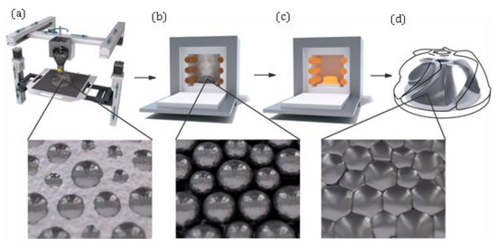
Figure 4.
Process scheme of an extrusion-based system: (a) 3D printing of the green part (b) debinding of the green part in a debinding furnace; (c) sintering of the resulting brown part in a high-temperature furnace; (d) final metal part [85].
The main advantage of FDM is its low technology and operation cost as it does not require expensive components such as lasers or electron sources and vacuum pumps in beam-based machines. Another advantage is the ability to build components combining both thermoplastics and metals within the same build which is not possible with other direct metal systems [83]. The FDM technology can also achieve build rates that are much higher compared to sintering and melting technologies [84].
Basically, there are three different approaches for extrusion-based AM. Material extrusion with plungers, screw-based, or filament-based. Metal extrusion AM is mainly used by screw-based or plunger-based approaches since metal filaments present multiple problems mostly due to their mechanical properties such as brittleness.
Various material extrusion approaches have been developed with the aim of direct metal 3D printing. Greulich et al. [86] developed a process called multiphase jet solidification (MJS). The 3D fiber deposition (3DF) is a plunger-based technique that allows the development of metallic parts with accurately controlled pore size, porosity and interconnecting pores [87]. The material is a composite that consists of a metal powder and a binder or rather dispersant. Mireles et al. [83] modified an FDM 3000 system to deposit low melting eutectic Bi58Sn42 and non-eutectic Sn60Bi40 materials for electronic circuitry applications amongst other things.
Powder-binder mixtures are currently the most promising solutions for extrusion-based AM [88]. Metal or ceramic powders are combined with a polymer and form a composite, either in pellet form or as a filament that can easily be extruded [89]. The granulate has the advantage of containing a higher metal content than filaments (approx. 55 vol.% and 30 vol.%, respectively). Recent studies have shown that filaments based on stainless steel 316L [90] and copper [91] can be processed successfully. However, Gong et al. [90] found that the 316L parts feature lower yield strength, UTS, and elastic modulus compared to AISI type SS 316L as well as laser melted SS 316L part. This is induced by the equiaxed grains and austenitic microstructure of the parts. A filament based on copper and a binder system based on paraffin wax, low density polyethylene, and stearic acid (PW–LDPE–SA) was developed and tested by Ren et al. [91].
A screw-based approach using conventional metal injection molding (MIM)-feedstock was introduced as composite extrusion modelling (CEM) by Lieberwirth et al. [85]. The final parts featured a compression strength of 2345 MPa and a density of 7.47 g/cm3 which is very close to the typical value for the density of 7.67 g/cm3 specified conventionally processed MIM parts. A CEM printed test part made from 316 as well as an optical microscopy of the microstructure are depicted in Figure 5.
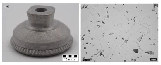
Figure 5.
(a) CEM printed and sintered 316L part and using conventional MIM feedstock Catamold (BASF, Ludwigshafen, Germany) (b) optical microscopy of CEM printed 316L part showing microstructure and inclusions of carbon and foreign particles comparable to conventional manufactured MIM parts.
Another plunger-based material extrusion approach is termed 3D gel-printing (3DGP), which selectively deposits a slurry layer-by-layer [92]. The 3DGP process is based on the in-situ polymerization of organic monomer binder and combines it with FDM. Recent approaches aim at printing binder-free metals. Kim et al. [93] developed a volumetric metal 3D printing system that can dissolve and eject binder-free molten Sn40Pb alloy materials. Another approach, which can be classified as filament-based extrusion, is by utilizing bulk metallic glasses (BMG) that show high mechanical properties. BMGs exhibit a supercooled liquid behavior, which can be used in FDM under similar conditions to those in thermoplastics. The supercooled liquid can be extruded in a similar fashion as thermoplastics [94]. In this case, there is no need for post-processing like a sintering process to remove a binding agent.
2.4. Cold Spray AM (CSAM)
Cold spray (CS) process was originally developed as a solid-state coating method for improving surface properties [95]. In CS process (known as dynamic gas cold spray) a supersonic gas jet (normally velocity of 300 to 1200 m/s) is used to accelerate powdered materials (diameter of 1–50 μm) through a de-Laval or similar converging/diverging nozzle and spray them onto a substrate. Deposition is achieved through local metallurgical bonding and mechanical interlocking which are caused by localized plastic deformation at the inter-particle and particle-substrate interfaces [96,97]. As there is no melting and solidification in CS, the process does not suffer from common deleterious defects in high-temperature deposition processes such as high porosity, oxidation, residual thermal stress, meting-induced phase transformation and re-crystallization [96].
As illustrated in Figure 6, there are two types of CS design according to the pressure of the propulsive gas: high pressure CS in which the working gas is nitrogen or helium at pressures above 1 MPa, and low-pressure CS that uses compressed air at pressure below 1 MPa. A wide range of pure metals can be deposited using high pressure CS, while low pressure CS is used for spraying a mixture of limited metal/ceramic powders [98,99,100]. Various aspects of both processes and their applications have been discussed through some comprehensive review papers [9,96,99,101]. The term ‘cold spray’ normally refers to high pressure CS. Hereafter, this nomenclature is followed through the paper as well.
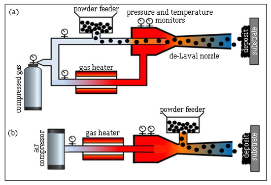
Figure 6.
Schematic view of (a) high and (b) low pressure CS.
CSAM of Al and Cu alloys have been widely investigated due to their excellent deformability, and thus cold-sprayability. Dense bulks from Cu and Cu alloys (Cu-Ag, Cu-Ag-Zr) with good interface bonding and mechanical properties have been printed using optimized CS with helium gas [9]. Post annealing could increase tensile strength of the printed bulks by 34.2% (from 125 to 168 MPa) and the interfaces between particles disappearing after annealing [9]. However, annealing can effectively reduce hardness [102]. As-sprayed Cu has poor ductility with elongation below 0.4%, while post annealed samples at 400 °C had elongation similar to pure Cu bulk [103]. Al deposits have slightly lower compactness than Cu deposits due to its lower density, although Al particle can be easily deposited [104,105,106]. The influence of post-annealing and solutionizing on mechanical properties of Al6061 and Al7075 deposits were studied by Rokni et al. [105,106,107].
The relatively high strength of stainless steel makes it difficult to print dense parts. Coddet et al. [108] studied the microstructure and mechanical properties of 304L stainless steel deposits. As-printed parts were fairly dense (porosity of 1.3%) with tensile strength of 525 MPa and a brittle fracture nature with elongation of about 7%. The annealed parts at 400 °C had increased tensile strength of 629 MPa without improved ductility.
It is quite challenging to cold spray dense Ti alloys parts. The CSAMed Ti alloys exhibit a relatively high level of porosity due to their active characteristics and reactions with surrounding air [109]. Wong et al. [110,111] investigated the influence of particle morphology and size distribution on CSed pure Ti and Ti-6Al-4V. Dense Ti deposits CSed (using nitrogen) with high tensile strength of 800 MPa and very poor ductility of (approx. 0.01%) was reported by Jahedi et al. [112]. According to the study by Vo et al. [113], the porosities of the CSed Ti-6Al-4V deposits using helium gas was lower by one order of magnitude than that nitrogen gas due to higher level of particle acceleration. The use of in-situ peening technique [114] (i.e., mixing of build powder with large ceramic powders), could result in dense Ti and Ti-6Al-4V deposits using cheaper nitrogen gas due to the “tamping effect” of CS [115].
It is very difficult to deposit dense parts from superalloys even using CS at high gas temperatures [116], so there has been a great focus on investigation of the post-heat treatments routes. It has been shown that high temperature heat treatment as well as the use of helium gas can effectively enhance properties of the CSAMed superalloys [117]. Levasseur et al. [118] proposed a pressureless sintering process to decrease porosity of Inconel 718 deposits from 2.5% to 0.2% and improve flexural strength and ductility.
2.5. Additive Friction Stir Deposition (AFSD)
This process is a solid-state metal AM process that uses heat and friction to bond materials layer-by-layer (Figure 7), developed by MELD manufacturing.
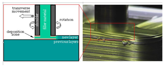
Figure 7.
Schematic view of AFSD process (left), AFSD head in operation (right image, courtesy of Aeroprobe Corporation, USA).
The AFSD involves a hollow rotating shoulder, through which the feed material is delivered in the form of either a solid rod or powder [119]. The rapid rotation of the hollow shoulder generates heat through dynamic contact friction at the shoulder/material and material/substrate interfaces [120]. The heated and softened material bonds with the substrate through plastic deformation at the interface. Post-heat treatment of the as-printed parts is not necessary due to low porosity and residual stress; however, the parts normally need post-machining/surface finishing.
The peak temperature of AFSD process normally ranges from 60 to 90% of the melting temperature [121]. However, a low shoulder transverse speed or a very high shoulder rotation frequency may result in adiabatic heating during deposition, and thus local melting. So, appropriate selection of process parameters is critical to prevent such phenomena and minimize defects [9]. AFSD provides important advantages of friction stir welding and friction stir processing such as the capability to process non-weldable alloys, and wrought microstructure formation [122,123]. In particular, the printed parts using AFSD have shown isotropic mechanical properties due to dynamic recrystallization and refined grains.
Multiple materials such as Nb/Cu and Ta/Cu have been successfully printed using AFSD process. No interfacial delamination was observed when applying a high shear stress at the interface through bending [119]. Also, customized reinforced Al and Mg-based alloys such as Al-Mo, Al-W, and Al-SiC have been fabricated with loading up to 30 Vol.% [119]. In addition to Al alloys, AFSD of high strength alloys such as nickel-based superalloys [121] and titanium alloys is possible.
2.6. Sheet Lamination Processes
2.6.1. Ultrasonic AM (UAM)
Ultrasonic additive manufacturing (UAM), known as ultrasonic consolidation (UC), is a hybrid additive/subtractive process that involves the layer-by-layer ultrasonic scrubbing of similar or dissimilar metal foils in the solid state with periodic cutting operation (often end-milling) to fabricate desired part geometry [124]. The process uses ultrasonic vibrations in a textured sonotrode to create a friction-like relative motion between two surfaces that are held together under pressure (Figure 8). This action, in turn, causes shearing and plastic deformation between asperities of the opposing surfaces, which disperses surface oxides and contaminants. As the asperities collapse, metal-to-metal contact is increased, creating solid-state metallurgical bonding between the parts through atomic diffusion. The UAM process can be used for fabrication of pure metals, alloys, and dissimilar material parts using high mechanical loads and high power ultrasonic [125].
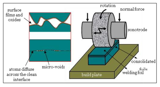
Figure 8.
Schematic view of UAM process.
The common defect in UAM-printed parts is micro-voids that are produced along the interfaces between bonded layers due to foil surface roughness, insufficient or excessive welding energy, and metal foil positioning inaccuracies [126]. Although printed metal parts using UAM possess high tensile/compressive strength and good wear resistance, the strength in build direction is markedly lower than the other directions [127]. Anisotropic mechanical behavior has been reported for printed Al6061 parts [128]. HIP has been found to be an effective post-treatment approach for eliminating the brittle fracture and improving the strength and ductility of UAM printed AL parts in the build direction [129,130].
The use of very high power UAM has been shown to improve elastic properties of the printed AL alloys [131]. Sridharan et al. [128] used very high power (VHP) UAM (9 kW) instead of low power (1.5 kW) for fabrication of 6061 Al alloy and could achieve a complete metallurgical bonding across the interfaces without any discernable voids; however, poor mechanical properties were observed in the build direction. The microstructural analysis of VHP-UAMed AA 3003 alloy revealed that the top and bottom bulk regions consist of the original elongated grains and fine equiaxed grains (very similar to the microstructure of the as-received foils), whereas the interface regions consist of only fine equiaxial grains due to the onset of recrystallization during VHP-UAM [132] (Figure 9).
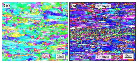
Figure 9.
(a) The Inverse Pole Figure (IPF) map of as-received original AA 3003 alloy foil in which the grains are elongated along the rolling plane, and fine equiaxed grains are observed between the elongated grains, (b) The IPF of the VHP-UAM sample in which the interface region is represented by the white colored arrows. Many grains in the both top and bottom bulk regions are elongated along the rolling plane of the original tape, and fine grains are seen between these elongated grains, while all grains in the interface region are fine and equiaxial [132].
The low operation temperature and the plastic flow of metals provide the opportunity to embed and/or encapsulate various electronic devices in to the metal matrix through the UAM process. Smart material structures could be printed by embedding fibres, conductor, dielectric, and nano-fibres of NiTi shape memory alloy into a metal matrix [133]. Carbon fibres [134], fibre Bragg grating (FBG) [135], polymer-coated and uncoated optical fibres [136], metal-coated optical fibres [137], and NiTi shape memory alloy fibres [138,139] could be successfully embedded into Al matrix with sufficient bond strength in the welded interfaces of the metal foils while retaining their functionality.
Moreover, solid-state nature of UAM allows joining of dissimilar metals without the formation of brittle intermetallics as seen in powder-bed fusion processes. High performance multi-material parts such as Al/Cu, Ni/Stainless steel, and Al/Ti are routinely produced using high power 9KW UAM [132]. Hehr et al. [140] combined UAM and metal matrix composite (MMC) materials to develop a novel functionally graded materials (FGM) for aerospace applications.
2.6.2. Friction Stir Additive Manufacturing (FSAM)
This process is the other type of friction-based technique that is a sheet lamination process. In FSAM, friction stir welding is used to bound stacked multiple metal sheets. A special friction pin is penetrated into the stacked sheets and then a welding line is created throughout the sheets by rotation and traverse movement of the pin. Large parts are produced by repeating the sheet stacking and friction welding, and further machining process to form the accurate external shapes. So, both AFSD and FSAM are intensive techniques as parts are printed through a severe plastic deformation at high temperatures, yet solid state. The main difference is that the FSAM is a hybrid additive/subtractive process that produces microstructures with cyclic variations [141,142], while in AFSD all layers are subjected to the same type of plastic deformation and friction-induced heating, and thus it can produce a much more homogeneous microstructure. Although both UAM and FSAM are hybrid sheet lamination processes, they differ in build layer thickness. FSAM uses thick metal sheets, for example 1.7 mm sheets of Mg-based WE43 alloy [141], while much thinner metal foils with thickness of ~0.1 mm are used in UAM process. Table 2 compares the three solid-state metal additive processes in detail.
Table 2.
Comparison of different solid-state beamless metal AM systems [9].
2.7. Wire and Arc AM
Wire and arc additive manufacturing (WAAM) is becoming more popular due to its high deposition rate, low production cost and the capability for fabricating large-scale components [143]. Contrary to blown powder processes such as laser cladding (CLAD) or laser metal deposition (LMD), the WAAM technology is considered a wire feed process. The wire is welded using an electric arc as a heat source to build near net shape parts in layers. The raw part must often undergo CNC milling to get its final condition. WAAM is also known as shaped metal deposition (SMD) or Rapid Plasma Deposition™ (RPD™).
WAAM is a promising technology for producing large metal components (up to several meters) with moderate complexity. Specifications of this technology can be roughly defined in a high build rate of up to 2500 cm3/h or 5–6 kg/h [144]. Many different metals and alloys can be processed with the WAAM process. The microstructure and mechanical properties of various metals, including titanium, aluminum, nickel, steel and other intermetallic materials fabricated by the various WAAM processes have been reviewed extensively [144,145,146,147]. In general, printed metal parts exhibits anisotropy in the mechanical properties and low surface quality in comparison to other AM technologies [144].
Furthermore, WAAM can be distinguished between the use of different heat sources. The WAAM process can use gas metal arc welding (GMAW or MIG), gas tungsten arc welding (GTAW or TIG) or plasma arc welding (PAW). Figure 10 shows schematic diagrams of the mentioned processes. In general, the deposition rate of GMAW-based WAAM is 2–3 times higher than that of GTAW-based or PAW-based methods [145]. However, the GMAW-based WAAM is less stable and generates more weld fume and spatter due to the electric current acting directly on the feedstock. The energy efficiency of arc welding processes in GMAW or in GTAW can be as high as 90% in some circumstances [145]. GTAW and PAW arc welding technologies have demonstrated to be more reliable processes for WAAM with fewer problems of sputtering, excessive heating, distortion or porosity than GMAW. However, both technologies do not feed the wire coaxially which leads to process variations when changing the welding direction causing extreme sensitivity to the arc length [144,148]. There are four main approaches of metal transfer in GMAW including: globular, short-circuiting, spray and pulsed-spray, each has distinct features [145].
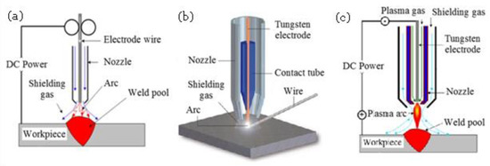
Figure 10.
Schematic view of the (a) GMAW, (b) GTAW, and (c) PAW process [149].
There are different arc welding technologies that are being used. Motion can be provided either by robotic systems or by computer numerical controlled gantries. TopTIG, for example, is a robotic GTAW welding technology with integrated wire feeder that distinguishes itself with the design of the welding torch. Cold metal transfer (CMT) is a modification of the short-circuit GMAW process which is based on controlled dip transference [149]. PAW can be considered a conventional welding technology, while CMT and TopTIG are evolutions of GMAW and GTAW, respectively.
2.8. Electrochemical AM Processes
There currently exist two electrochemical metal-AM processes, namely, electrochemical fabrication (EFAB) and FluidFM 3DP. The EFAB (a trademark of Microfabrica, Van Nuys, CA, USA) method uses electrochemical deposition and subtractive planarization in a layer-by-layer process to build 3D micro-objects [150]. It involves three main processes in each layer: electroplating of sacrificial support material using a proprietary method called “instant masking”, electroplating of build material, and planarization, respectively. Figure 11a shows the steps for fabrication of metal parts using the EFAB method.
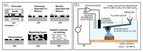
Figure 11.
Schematic view of (a) EFAB [150] and (b) FluidFM printing cell. the iontip dispenses the electrolyte into a buffer bath. At the working electrode, Cu2+ ions are deposited as solid copper [151].
The EFAB has been developed for true 3D manufacturing of metal microparts with features as fine as 20 μm and accuracy of 2 μm. So far, limited metals have been developed by Microfabrica to be processed through EFAB, including: VALLOY-120TM, EDURA-180TM, copper, and biocompatible noble palladium. More information about the material properties can be found in the literatures [150].
FluidFM 3DP process is another electrochemical technique developed recently by Cytosurge AG (Opfikon, Switzerland). It combines electrodeposition, scanning probe microscopy (SPM), and precise liquid ink dispensing [151]. The system uses atomic force microscopy (AFM) cantilevers with a microfluidic channel and a hollow tip. A microfluidics control system applies a pressure to a reservoir containing the electrolyte solution to push it through the cantilever and out of the tip (Figure 11b). The tip is part of the printing head that has 3D movement inside buffer vat. The metallic ions are converted to solid metals by applying an appropriate potential to the build substrate. There is a real-time feedback to detect the tip deflection. As a voxel reaches completion, the top side of the voxel interacts with the tip, exerting force that results in a few nanometer deflection of the cantilever. When specific amount of deflection is reached, the voxel is considered as printed and the tip is moved to the next voxel.
2.9. 3D Screen Printing (3DSP)
This process has been developed by researchers at Fraunhofer Institute for Manufacturing Technology and Advanced Materials (IFAM), Branch Lab Dresden (Germany) [152]. It uses the classical screen-printing technique through an adapted layer-by-layer process to stack multilayers of the desired layout on top of each other and create metal parts. For each layer, a printing screen is fabricated using a photolithographic process. Metal paste containing metal particles and organic binder/additives is pushed through the screen using a squeegee being moved over the screen. Each printed layer (normal thickness of 5–15 µm) is subsequently dried in a furnace. These steps are repeated to create the final green part that is then transferred into an oven for debinding and sintering.
The metal paste formulation and its rheological behavior is the key parameter to achieve high accuracy detailed parts. The process has limitation in terms of solid particle loading (up to 50 Vol.%) as too high particle concentration can result in undesired shear thickening behavior. A wide range of metals such as stainless steel, copper, titanium, and hard metals have been successfully fabricated with surface roughness of Ra = 5–10 µm [153]. Also, the printing paste can be changed during the print process while the printing screen is kept the same, allowing for fabricating the multiple materials. A ceramic (ZrO2)/metal (17-4-PH) sandwich structure, and copper/ceramic 3D patterns with line width of 150 µm could be printed and sintered without cracks [153].
3. Impact and Applications
3.1. Processes Comparison
It is believed that the beamless metal AM can improve the development trajectory of metal AM. It can lower technology and operation costs, overcome the intrinsic safety concerns associated with beam-based systems [4], and possess advantages over beam-based AM technologies as illustrated in Figure 12. The access to cost-effective beamless techniques such as extrusion-based metal AM systems facilitates wider adoption of and a greater business value from this technology. This accessibility allows the small/medium size companies and job shops to enter the metal-AM market whereby they can shorten lead-time, increase their market penetration and share, and expand their product portfolio. In particular, beamless metal AM would hold great potential for less developed countries that possess inadequate production infrastructure. In addition to impact on small public and private sector companies, the large manufacturing companies can also take the advantages of totally new manufacturing possibilities offered by beamless metal AM. For example, AM of high density mega-scale parts is now possible, while it is challenging or impossible for current powder-bed metal-AM systems due to equipment size limitations. Moreover, metal parts with refined grains at higher strength and isotropic mechanical properties are now achievable.
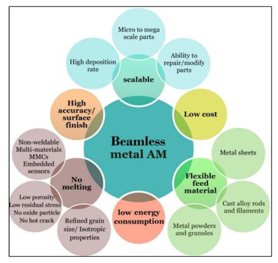
Figure 12.
The main possibilities and advantages of the beamless metal-AM over beam-based systems they are low energy, can achieve higher dimensional accuracy, can be used for printing parts from micro to mega scale parts with improved mechanical properties as they do not comprise material melting and rapid solidification.
An in-depth understanding of the strengths/weak points and comprehensive knowledge on capabilities and limitations of each beamless metal AM technology is an important step in selecting the appropriate process for a particular application. A comparison of the key beamless metal AM systems has been presented in Table 3.
Table 3.
Comparison of various beamless metal AM processes.
Figure 13, Figure 14 and Figure 15 graphically compare the main beamless metal AM systems in terms of part complexity, minimum feature size, and part size and Figure 16 depicts the identification map of the beamless metal AM technologies.
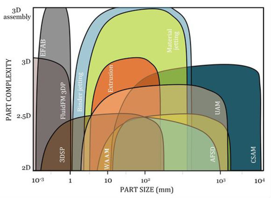
Figure 13.
Comparison of the key beamless metal AM systems in terms of part complexity and size. EFAB, 3DSP, FluidFM 3DP are suitable for micro-scale applications. Binder jetting is a scalable process that can be used for micro to medium size parts while material jetting and extrusion methods are normally used for medium size parts. In contrast, CSAM, AFSD, UAM, and WAAW are more suitable for medium to mega-scale parts.
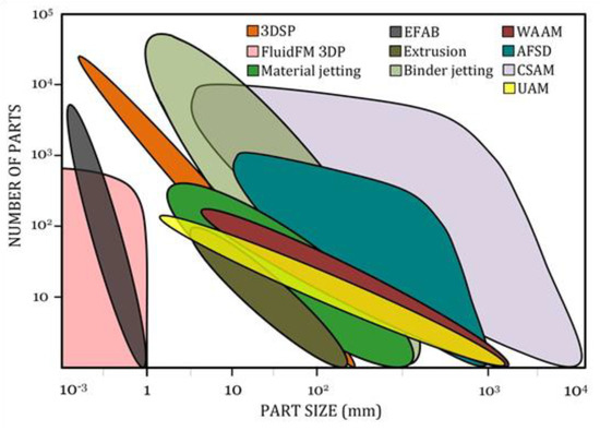
Figure 14.
Comparison of the key beamless metal AM systems in terms of part size and productivity. As can be seen, UAM, WAAM, material jetting, extrusion, and FluidFM 3DP are suitable for low-volume production while binder jetting, 3DSP, CSAM, and EFAB have higher deposition rate for high-volume production of metal parts.
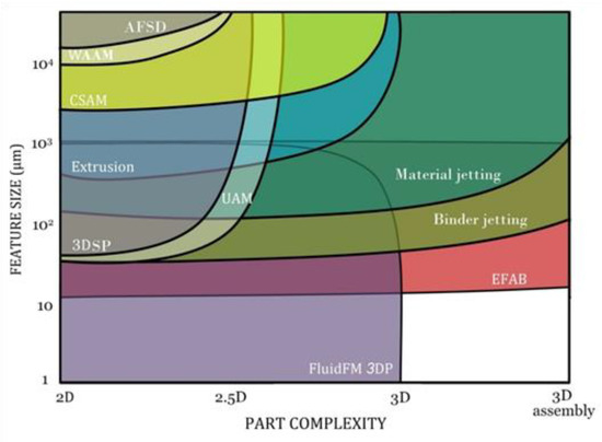
Figure 15.
Comparison of the key beamless metal AM systems in terms of part complexity and minimum feature size. Material jetting, binder jetting, and EFAB processes have the capability to print sophisticated 3D parts and assemblies. FluidFM 3DP, extrusion, and CSAM can be used for manufacturing of true 3D parts, while the other processes are normally served for parts with less complexity.
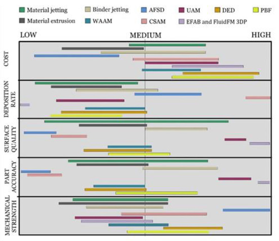
Figure 16.
The identification map of the beamless metal AM technologies in comparison with DED and PBF beam-based methods. As can be seen, AFSD offers the highest mechanical strength and the lowest process and operation cost. Extrusion process is also a low-cost process suitable for low-volume production, while CSAM offers the highest deposition rate (up to 38 kg/h). EFAB and FluidFM 3DP processes possess the highest dimensional accuracy and surface quality.
3.2. Application Fields
The application fields of beamless metal AM systems can be classified into three main areas including micro, medium, and mega-scale parts that are discussed in this section.
3.2.1. Micro-Scale Parts
The EFAB and FluidFM 3DP are the two current beamless methods that have demonstrated great potential for true 3D micro-manufacturing. The current micro-fabrication techniques normally include multiple production steps which are costly and need strictly safety standards. The FluidFM 3DP is a single step process with potential to overcome these barriers and offer higher efficiency to different micro-scale industries. The size of features printed with FluidFM pinpoint 3DP range from 1 µm to 1000 µm (Figure 17) using a unique 300 nm pipette, allowing flow rates as small as a few femtolitres per second. In particular, the technique allows adding complex parts 3D printed with a high degree accuracy directly onto existing structures or surfaces, on contact pads that are pre-defined on the surface of integrated circuit (IC) boards, on Micro-Electro-Mechanical Systems (MEMS), etc.
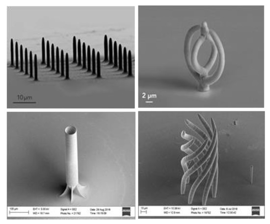
Figure 17.
Uniform pillars and complex copper parts printed in single step using FluidFM 3DP without support structure (Courtesy of Cytosurge AG).
The EFAB process has also shown great applicability for true 3D printing of robust sub-millimeter metal parts and mechanical mechanisms for medical, aerospace and semiconductor industries. It provides designers with the new possibilities to commercially produce sophisticated fully assembled medical devices and complex mechanisms with multiple discrete biocompatible components. In particular, as the mechanisms are 3D printed in a finished fully assembled state there is no concern about micro-scale assembly challenges.
In addition, proprietary BJ technology is capable of printing very fine parts with micro-features. For better assessment, the authors conducted a benchmarking study. A tissue staple was used as a benchmark sample and printed using Digital Metal® (Höganäs, Sweden) BJ technology at two different sizes to be compared with SLM and EFAB technology. The results of the assessment are presented in Figure 18 and Figure 19.
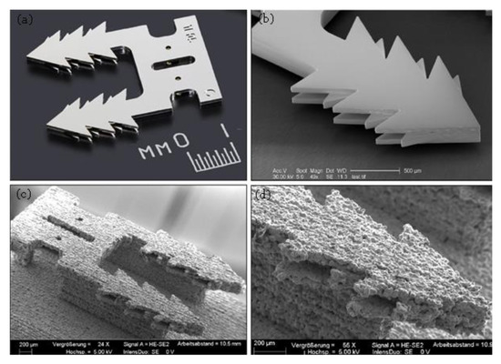
Figure 18.
A metal tissue staple 3D printed using (a,b) EFAB (Courtesy of Microfabrica, USA) and (c,d) BJ technology (material 316L).
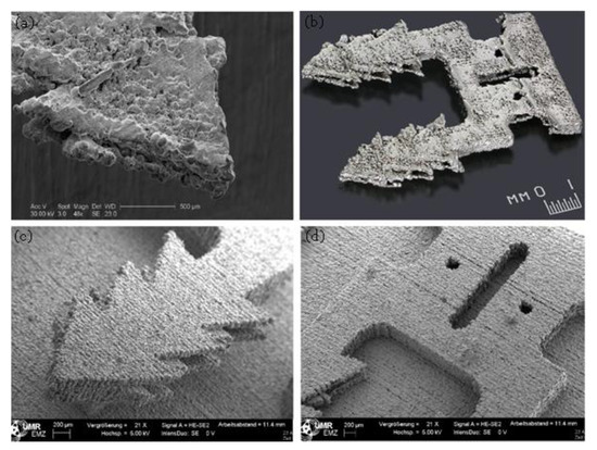
Figure 19.
The double enlarged staple (to allow fabrication using beam-based system) printed using (a,b) SLM process (source: MICA Freeform vs Selective Laser Melting published by Microfabrica, USA) and (c,d) BJ technology (material 316L).
As can be seen in Figure 18, the printed sample using EFAB technology possesses superior surface finish and accuracy. The lower surface quality and definition of BJ part is apparent, in particular in the teeth region and central locking hole that was designed with undercut features. However, it still proves the capability of BJ to print micro-scale parts that is not possible using SLM or EBM techniques.
Figure 19 Compares the double enlarged staple printed using SLM process (Mlab Cusing SLM machine, Concept Laser, Lichtenfels, Germany) and BJ technology (Digital Metal’s 3D printer). Although both SLM and BJ use powder bed technique the BJ part has significantly higher surface quality and part definition. Very thin walls (thickness down to 80 µm) could be printed successfully using BJ process (Figure 20a). So, the BJ process fills the gap between SLM and EFAB technologies in terms of feature size and surface finish. Also, 3DSP process is an emerging technique for serial production of small parts (Figure 20b). The print quality and minimum feature size of 3DSP and BJ falls to relatively similar level. A sample part printed using both techniques is shown in Figure 20c,d. The part produced using 3DSP could achieve a better dimensional tolerance. However, 3DSP cannot compete with BJ technology in terms of part complexity. In 3DSP, a single printing screen is used for a certain number of cycles to create several layers with similar shapes, while many screens must be produced and changed during print for stacking of layers with different shapes that is practically impossible. The process is well suited for mass production of small and simple geometry parts with fine details and walls with high aspect ratios.
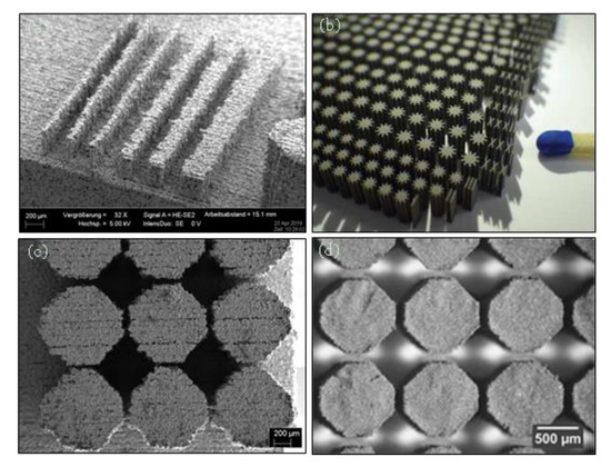
Figure 20.
(a) Thin walls 316L printed using BJ technology, (b) serial production of micro-parts aspect ratio of 1:50 printed using 3DSP [152], (c) a benchmarking sample part printed using BJ technology, (d) the benchmark sample printed using 3DSP [162].
3.2.2. Medium Size Parts
Metal BJ is well-suited for truly cost-effective serial production of small to medium size parts for different applications such as medical equipment, portable electronics, luxury watches, etc. that is not currently possible using other beam-based metal-AM systems. Metal BJ possess superior benefits over beam-based powder bed AM systems such as reduced costs with higher manufacturing throughput (as there is no need for support), much less residual stress, increased geometrical complexity and print speed.
Also, BJ process surpasses metal injection molding (MIM) in terms of design flexibility and part complexity, allowing it to penetrate new application fields that are currently not approachable for MIM. Meanwhile, the BJ can complement MIM rather than compete with it. The current MIM producers already have the infrastructure and facilities to process green parts. So, the BJ can be effectively integrated to MIM process for fabricating prototypes and/or small batches before investing in expensive MIM tools for mass production.
Digital Metal®’s BJ technology enables detailed fine metal parts to be printed at high volume with remarkably higher precision and surface quality than SLM or EBM processes. The other commercial systems like ExOne (North Huntingdon, PA, USA) and GE Additive (beta H2 binder jetting platform, Cincinnati, OH, USA) have targeted production of medium to large scale parts for automotive and aerospace applications where the BJ technology removes the need for casting and eliminates further expenses such as tooling and molds.
In addition, extrusion-based AM systems can be used for printing of medium size metal parts, in particular, in medical applications such as titanium implants and scaffolds. They can also be served for parts like jigs and fixtures, auto/aero parts, electroforming mandrels, encapsulation molds, dies, electronic joining applications, as well as printing 3D electronic circuitry [82]. Low temperature alloys can be easily processed using direct metal extrusion printing but lack the high mechanical properties of the composite-based FDM processes. With the use of BMGs, the 3D printing process can offer a solution to escape some property-processability tradeoffs.
To date, a large number of both research and commercial works on liquid metal jetting have been demonstrated; however, much of the reports confine to 2D and/or 2.5D printing of low melting point metals for electronics applications [10]. The latest developed liquid metal jetting system (MagnetoJet Technology by Vader Systems, New York, NY, USA) can print medium size parts with arbitrary shapes from low melting point alloys, while lack of support structure remains as the key weak point of the system. In contrast, XJet’s low-temperature nanoparticle inkjet 3D printer can produce complex medium size metal components with high accuracy (dimensional tolerance of 50 to 100 µm depending on part size) and smooth surface finish due to its ultra-thin layer thickness (8–10 µm). Complex 3D geometries and sophisticated assemblies are possible using water-soluble support material. Theoretically, the XJet printed parts have isotropic properties and higher green strength than BJ due to higher level of layer packing.
3.2.3. Mega-Scale Parts
A great focus has been given to the solid-state beamless metal AM technologies for different mega-scale applications in the past few years as reflected by the number of publications [9]. As there is no melting in CSAM, metals are not affected by thermal-related defects and the aluminum or titanium parts do not need to be printed in an inert gas or vacuum sealed chamber, allowing fabrication/repair of much larger components. Also, the CSAM minimizes waste of expensive material by improving the material utilization ratio (buy-to-fly) and machining from near-net-shape parts, not large billets. More important, graded or multiple materials can be effectively printed to tailor functionality of the part.
The spot size of the CS process is currently above 4 mm which is significantly larger than other laser-spots in powder-bed AM systems. Therefore, CS-based AM is considered as an ideal choice for cost-effective printing of near-net-shape features onto the available parts. Meanwhile, the CS head can be integrated with an industrial robot arm for super-fast direct printing of very large metal parts with intricate shapes that is not possible using other metal-AM systems (Figure 21a). Titomic (Australia) has commercialized the largest and fastest metal 3D printer with an output size of 9 m × 3 m × 1.5 m for industrial scale production of titanium parts without any shape constrain at ultra–high deposition rate of 38 kg/h.
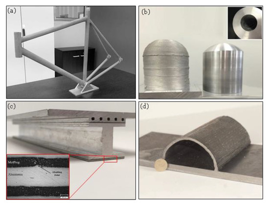
Figure 21.
(a) A single step 3D printed titanium bicycle frame in 25 min using Titomic’s CSAM system (Courtesy of Titomic, Melbourne, Australia), (b) Al6061 hollow dome as fabricated by MELD technology and after finish machining, 115 mm tall, 100 mm diameter part with 25 mm wall thickness, fabrication time: 2 h (Courtesy of Aeroprobe, Christiansburg, VG, USA), (c) MMC laminates (MetPreg) composed of continuous alumina fibers and a matrix of pure aluminum are selectively layered for selective reinforcement of the rib structure (Courtesy of Fabrisonic, Columbus, OH, USA), (d) 50 mm radius semicircle printed using WAAM [163].
The other solid-state beamless AM systems, namely, UAM and fiction-based AM systems have been highly regarded by both scientific community and industry. The first commercialized technology of AFSD was developed and patented by Aeroprobe Corporation as “MELD Technology” for printing of a wide range of materials from Al, Mg, titanium alloys, nickel-based superalloys to non-weldable metals at high deposition rates. MMCs can also be deposited through pre-mixing different powders and consolidating them as the feed material. The main application areas of AFSD are repair, rapid manufacture of net-shape large parts (Figure 21b) and production of non-weldable alloys.
UAM has also shown encouraging success in near room temperature fabrication of parts that enables a multitude of thermal-sensitive electronics and sensors to be embedded into the solid metal part, exactly where needed. Also, UAM enables designers to reliably fabricate interwoven channels within a multiple material part printed in a single step. High performance multi-material parts for a wide array of engineering applications, including: coating, heat transfer, strengthening materials, and light weighting can be printed using UAM. To strengthen materials, MMCs can be printed selectively within the part by using continuous fibers at specific high-stress regions (Figure 21c).
In contrast to UAM, WAAM is preferred for the production of even larger parts due to its high deposition rate, high material utilization rate, low production and equipment cost, and high equipment flexibility and scalability. In comparison with subtractive processes, WAAM systems have been shown to reduce fabrication time by 40–60% and post-machining time by 15–20% depending on the component size [145]. Furthermore, the cost of a part produced by the WAAM process is an order of magnitude lower than the cost when produced by laser-based powder processes such as SLM. Applications in the aerospace industry include cryogenic tanks, fuselage, shells and arbitrary profiles (Figure 21d).
4. Challenges and Future Perspectives
As a consequence of what was discussed, beamless metal AM is well on its way to becoming a viable and established standard manufacturing tool for cost-effective metal part prototyping and rapid manufacturing. The economic and efficiency advantages ensure that beamless metal AM systems will be subjected to extensive investigations in the future. However, the growth of beamless metal AM has been hampered significantly by technical challenges inherent to each process that are currently limiting the wider adaptation of these promising technologies.
Despite its advantages, metal BJ has been adopted less than beam-based powder bed systems that might be attributed to the inherent porosity present in the parts, even although post-infiltration and/or liquid phase sintering followed by HIP are normally applied to increase density of the parts. In addition, there are some technical challenges preventing wider use of metal BJ. As-printed green parts are relatively fragile which makes them prone to failure, post thermal treatment increases the lead time remarkably, and for larger parts it results in distortion. Future research may be focused on development of novel techniques for enhancing density without sacrificing homogeneity of material, part accuracy, and/or process scalability. Meanwhile it is worth broadening the range of printable materials through the development of new predictive models and optimization of process parameters, and expanding the application field of BJ into composite materials by overcoming powder segregation and co-sintering issues. Moreover, more efforts on high-speed AM (HSAM) using inkjet-based 3D printing systems is expected to be made in the future although the BJ systems possess a higher speed than beam-based powder bed AM systems. This claim has already been fueled by companies such as HP (Palo Alto, CA, USA), and Desktop Metal (Burlington, MA, USA) with prioritizing the print speed in their new metal BJ commercial 3D printers. HP’s Jet Fusion and MultiJet Fusion (MJF) technologies offer high build speed and quality, and at lower cost than competitive 3D printers. These technologies are quite similar to High Speed Sintering (HSS) process [164]. HP’s MJF, uses inkjet printheads to deposit both a fusing agent and a detailing agent onto a bed of powder before sintering them with a set of infrared lamps [165], while HSS does not use a detailing agent. HSS has not been used for true metal 3D printing, while infrared-assisted sintering of inkjet printed metal tracks on substrates have been reported [166]. HP’s Metal Jet printers uses thermal Inkjet printheads to precisely deliver water-based binder to industrial MIM metal powders for reduce costs. It uses multiple printbars (six printheads arranged in two printbars on the print carriage) for high productivity and nozzle redundancy. Desktop Metal’s printer (production model) uses “single pass jetting” technology that employs thousands of piezo nozzles to spray millions of binder droplets per second on the metal powder [167].
The FluidFM 3DP is a newly developed 3D printing method that needs further research and design upgrade to be considered as a mature and reliable technology. The deposition rate needs to be improved for achieving larger build size. Since introduction of the technology the deposition rate of FluidFM 3DP could be increased from 3µm3/sec to 375µm3/sec for pure metal parts [153]. The increase in printing speed is expected to be considered as a growth strategy. In addition, so far limited metals including copper, silver and gold could be printed, while a great focus should be given on development of other strategic metal systems such as Cd, Cr, In, Zn and Pt in the future.
EFAB process has currently some design constrains such as maximum number of build layers (maximum part height of 1.25 mm) and, more important, parts from very limited metals can be currently manufactured. Smart materials are suggested to be developed in the future for manufacturing of electromagnetism or shape memory-based sensing and actuation systems.
The growth of liquid metal jetting has been hampered by some challenges. The scalloped surface topography of solidified droplets and the staircase effect reduce surface quality. The previous studies on understanding the mechanism of metal droplets impacting and solidification, and optimization of process parameters have been very useful. Further research work should focus on the development of new printing mechanisms, and in-depth understanding of the morphology of surface topography through experiment and modeling would be helpful for adaptation of liquid metal jetting. The low-temperature 3D printing of metallic parts is quite promising. However, it suffers from relatively low print speed (and thus limited build size) due to the use of nanoparticles in thin build layers. In addition, preparation of nanoparticle metal inks and reliable printing of the inks without nozzle clogging and/or particle sedimentation seems to be quite challenging.
CSAM is a vital breakthrough and revolutionary technology and redefines manufacturing components of complex geometry/3D shapes in a single step. Despite the merits highlighted for CSAM, there exist deficiencies that should be addressed through future research activities. The influence of spraying parameters on mechanical properties of hard-to-form materials such as anisotropic behavior is not well understood and entirely agreed upon by researchers. Further experimental studies are required with the aim of developing a standard fabrication strategy for determining optimal part properties. Moreover, most of the research works have focused on the use of CSAM for part restoration and modification, while direct manufacturing of complex parts is an attractive and challenging research topic. In particular, fabrication of parts at higher spatial resolution through development of new spraying systems with smaller spot size for minimizing post-machining processes is a vital step to be further explored.
There are huge application field for friction-based AM in industries where large-scale parts are required such as aviation, defense, automotive, energy, etc. To get the best out of these countless possibilities, development of new practical applications for friction-based AM should be considered as a research focus in the future. The low resolution of material deposition as well as the demand for secondary subtractive machining and/or grinding steps for achieving the final shape are the key barriers to the widespread adaptation of friction-based AM technology for industrial productions. The use of new tool deigns in AFSD with a smaller shoulder diameter might be an effective measure to improve resolution as the amount of deposited plasticized material in each step is decreased. Development of an in-situ quality control system can be another approach to better monitor the FSAM process and enhance resolution and reliability. A closed loop control containing high-speed infrared camera and various sensors is proposed to be used for real-time monitoring of weld formation and in-situ measuring of the peak temperature and cooling rate.
Realization of mentioned potentials for wider applications of UAM is stifled by high material wastage, anisotropic properties and low mechanical strength in build direction, as well as design constrains such as height to width ration. The production cost of UAM parts is also relatively high, and thus the process has been adapted to limited industries such as aerospace or automotive where functionality and/or properties of the engineered multiple material parts can compensate the high costs. The high production cost might be decreased in the feature as metal foils are widely available on the market for prices approaching that of billet. However, the process might not be considered as a route for single material parts fabrication since the high wastage of expensive materials in UAM process remains as the key barrier for cost reduction in the future. The future works should focus on more in-depth investigation of the process parameters affecting ultrasonic welding-induced pores in the interface with the aim of improving mechanical properties. Techniques such as laser-assisted pre-heating of the metal foils might be useful for increasing plastic deformation and thus enhanced bonding.
Many challenges remain with WAAM technology as well. A part from the low resolution of this technology, microstructural anisotropy and porosity remain some of the key challenges that need to be addressed. At the moment, only components with moderate complexity such as flanges or stiffened panel are feasible. Technical challenges like distortion from excessive heat input, relatively poor part accuracy caused by the “stair stepping” effect and poor surface finish keep the technology from being used in more complex and filigree components. The control of residual stresses and distortions especially for the large-scale WAAM process is of major concern. It not only has an effect on the part tolerances but it can also result in premature failure.
The low cost of FDM systems has led to one of the highest adoption rates among AM technologies. However, metal-based FDM systems are not yet developed enough to see widespread use. Further development in print speed through high-aspect-ratio (HAR) nozzles can lead to HSAM of metals [167]. Most approaches with extrusion-based AM with metals use a composite material that needs to be treated after the initial printing process. This can further lead to other tradeoffs such as multi-material implementation or in regard to mechanical properties. The ratio of the contents is also limited to its processability. Frequent buckling failures during the extrusion phase, for example, can cause an interruption of the process. In this context, working with established MIM feedstock holds great promise for the future since a broad range of cost-efficient MIM feedstocks containing various types of metals are already available. Furthermore, it has already been demonstrated that printed parts can achieve mechanical properties that are comparable to values specified for the final MIM parts.
5. Conclusions
This paper presented a review on the key beamless metal AM processes, progress and future developments. The sintering-based techniques such as BJ and extrusion-based techniques have demonstrated great potential for cost-effective serial production of small parts and low volume production of medium size parts, respectively. On the other hand, the electrochemical processes such as EFAB and FluidFM 3DP techniques have been able to meet the resolution requirements in micro-manufacturing industry while they provide new possibilities in terms of part complexity. Also, the solid-state beamless techniques provide the opportunity to print mega scale parts with improved mechanical strength. In particular, CSAM process benefits from super-fast metal printing speed, making it well-suited for true industrial production of large parts in the near future.
Author Contributions
Conceptualization, M.V. and H.S.; search and analysis of literature, M.V., P.D. and H.S.; design of experiments and analysis of experimental results, M.V. and H.S.; data curation, M.V.; writing—original draft preparation, M.V. and P.D.; writing—review and editing, H.S.; visualization, M.V.; supervision, H.S. All authors have read and agreed to the published version of the manuscript.
Funding
The authors acknowledge financial support by the DFG and the University Rostock within the funding program Open Access Publishing.
Acknowledgments
The authors would like to express their sincere gratitude to Alexander Sakratidis of Digital Metal, Sweden and Clemens Lieberwirth of AIM3D, Germany for their great support in printing of the benchmark samples. The authors also thank Marcus Frank and Armin Springer (Electron Microscopy Centre, University Medical Center Rostock) and Georg Schnell (Chair of Microfluidics, University of Rostock) for SEM imaging. The authors would extend their appreciation to Edgar Hepp of Cytosurge AG, Switzerland, Arun Veeramani of Microfabrica Inc., USA, David B. Wallace of MicroFab Technologies Inc., USA for their helpful information.
Conflicts of Interest
H.S. is co-founder of the company AIM3D, Rostock, Germany. The company AIM3D and the funder had no role in the design of the study; in the collection, analyses, or interpretation of data; in the writing of the manuscript, or in the decision to publish the results.
References
- Wohlers, T. Wohlers Report 2018: Additive Manufacturing and 3D Printing, State of the Industry; Wohlers Associates: Fort Collins, CO, USA, 2018. [Google Scholar]
- Standard Terminology for additive Manufacturing Technologies; American Society for Testing and Materials (ASTM) International: West Conshohocken, PA, USA, 2013.
- Lewandowski, J.J.; Seifi, M. Metal Additive Manufacturing: A Review of Mechanical Properties. Source 2016, 46, 151–186. [Google Scholar] [CrossRef]
- Gu, D.D.; Meiners, W.; Wissenbach, K.; Poprawe, R. Laser additive manufacturing of metallic components: Materials, processes and mechanisms. Int. Mater. Rev. 2012, 57, 133–164. [Google Scholar] [CrossRef]
- DebRoy, T.; Wei, H.L.; Zuback, J.S.; Mukherjee, T.; Elmer, J.W.; Milewski, J.O.; Beese, A.M.; Wilson-Heid, A.; De, A.; Zhang, W. Additive manufacturing of metallic components–Process, structure and properties. Prog. Mater. Sci. 2018, 92, 112–224. [Google Scholar] [CrossRef]
- Körner, C. Additive manufacturing of metallic components by selective electron beam melting—A review. Int. Mater. Rev. 2016, 61, 361–377. [Google Scholar] [CrossRef]
- Martin, J.H.; Yahata, B.D.; Hundley, J.M.; Mayer, J.A.; Schaedler, T.A.; Pollock, T.M. 3D printing of high-strength aluminium alloys. Nature 2017, 549, 365. [Google Scholar] [CrossRef]
- Murr, L.E.; Gaytan, S.M.; Ramirez, D.A.; Martinez, E.; Hernandez, J.; Amato, K.N.; Shindo, P.W.; Medina, F.R.; Wicker, R.B. Metal Fabrication by Additive Manufacturing Using Laser and Electron Beam Melting Technologies. J. Mater. Sci. Technol. 2012, 28, 1–14. [Google Scholar] [CrossRef]
- Li, W.; Yang, K.; Yin, S.; Yang, X.; Xu, Y.; Lupoi, R. Solid-state additive manufacturing and repairing by cold spraying: A review. J. Mater. Sci. Technol. 2018, 34, 440–457. [Google Scholar] [CrossRef]
- Hon, K.K.B.; Li, L.; Hutchings, I.M. Direct writing technology—Advances and developments. Cirp Ann. 2008, 57, 601–620. [Google Scholar] [CrossRef]
- Gao, F.; Sonin, A. Precise deposition of molten microdrops: The physics of digital microfabrication, Proceedings of the Royal Society of London. Ser. A Math. Phys. Sci. 1922, 444, 533–554. [Google Scholar]
- Vaezi, M.; Seitz, H.; Yang, S. A review on 3D micro-additive manufacturing technologies. Int. J. Adv. Manuf. Technol. 2013, 67, 1721–1754. [Google Scholar] [CrossRef]
- Chang, S.; Attinger, D.; Chiang, F.P.; Zhao, Y.; Patel, R.C. SIEM measurements of ultimate tensile strength and tensile modulus of jetted, UV-cured epoxy resin microsamples. Rapid Prototyp. J. 2004, 10, 193–199. [Google Scholar] [CrossRef]
- Roth, E.A.; Xu, T.; Das, M.; Gregory, C.; Hickman, J.J.; Boland, T. Inkjet printing for high-throughput cell patterning. Biomaterials 2004, 25, 3707–3715. [Google Scholar] [CrossRef] [PubMed]
- Orme, M.; Liu, Q.; Smith, R. Molten Aluminum Micro-Droplet Formation and Deposition for Advanced Manufacturing Applications. Alum. Trans. 2000, 3, 95–103. [Google Scholar]
- Yamaguchi, K.; Sakai, K.; Yamanaka, T.; Hirayama, T. Generation of three-dimensional micro structure using metal jet. Precis. Eng. 2000, 24, 2–8. [Google Scholar] [CrossRef]
- Chao, Y.-P.; Qi, L.-H.; Xiao, Y.; Luo, J.; Zhou, J.-M. Manufacturing of micro thin-walled metal parts by micro-droplet deposition. J. Mater. Process. Technol. 2012, 212, 484–491. [Google Scholar] [CrossRef]
- Yingxue, Y.; Shengdong, G.; Chengsong, C. Rapid prototyping based on uniform droplet spraying. J. Mater. Process. Technol. 2004, 146, 389–395. [Google Scholar] [CrossRef]
- Park, C.B.; Fang, M.; Chandra, S. Building three-dimensional objects by deposition of molten metal droplets. Rapid Prototyp. J. 2008, 14, 44–52. [Google Scholar]
- Luo, J.; Qi, L.-H.; Jiang, X.-S.; Zhou, J.-M.; Huang, H. Research on lateral instability of the uniform-charged droplet stream during droplet-based freeform fabrication. Int. J. Mach. Tools Manuf. 2008, 48, 289–294. [Google Scholar] [CrossRef]
- Cao, W.; Miyamoto, Y. Freeform fabrication of aluminum parts by direct deposition of molten aluminum. J. Mater. Process. Technol. 2006, 173, 209–212. [Google Scholar] [CrossRef]
- Chao, Y.-P.; Qi, L.-H.; Zuo, H.-S.; Luo, J.; Hou, X.-H.; Li, H.-J. Remelting and bonding of deposited aluminum alloy droplets under different droplet and substrate temperatures in metal droplet deposition manufacture. Int. J. Mach. Tools Manuf. 2013, 69, 38–47. [Google Scholar] [CrossRef]
- Liu, Q.; Orme, M. On precision droplet-based net-form manufacturing technology, Proceedings of the Institution of Mechanical Engineers. Part B J. Eng. Manuf. 2001, 215, 1333–1355. [Google Scholar] [CrossRef]
- Zhong, S.Y.; Qi, L.H.; Luo, J.; Zuo, H.S.; Hou, X.H.; Li, H.J. Effect of process parameters on copper droplet ejecting by pneumatic drop-on-demand technology. J. Mater. Process. Technol. 2014, 214, 3089–3097. [Google Scholar] [CrossRef]
- Yamaguchi, K. Generation of 3-dimensional microstructure by metal jet. Microsyst. Technol. 2003, 9, 215–219. [Google Scholar] [CrossRef]
- Jiang, X.S.; Qi, L.H.; Luo, J.; Huang, H.; Zhou, J.M. Research on accurate droplet generation for micro-droplet deposition manufacture. Int. J. Adv. Manuf. Technol. 2010, 49, 535–541. [Google Scholar] [CrossRef]
- Amirzadeh, A.; Raessi, M.; Chandra, S. Producing molten metal droplets smaller than the nozzle diameter using a pneumatic drop-on-demand generator. Exp. Ther. Fluid Sci. 2013, 47, 26–33. [Google Scholar] [CrossRef]
- Luo, J.; Qi, L.; Tao, Y.; Ma, Q.; Visser, C.W. Impact-driven ejection of micro metal droplets on-demand. Int. J. Mach. Tools Manuf. 2016, 106, 67–74. [Google Scholar] [CrossRef]
- Tropmann, A.; Lass, N.; Paust, N.; Metz, T.; Ziegler, C.; Zengerle, R.; Koltay, P. Pneumatic dispensing of nano- to picoliter droplets of liquid metal with the StarJet method for rapid prototyping of metal microstructures. Microfluid. Nanofluid. 2012, 12, 75–84. [Google Scholar] [CrossRef]
- Lass, N.; Riegger, L.; Zengerle, R.; Koltay, P. Enhanced Liquid Metal Micro Droplet Generation by Pneumatic Actuation Based on the StarJet Method. Micromachines 2013, 4, 49–66. [Google Scholar] [CrossRef]
- Zenou, M.; Sa’ar, A.; Kotler, Z. Laser jetting of femto-liter metal droplets for high resolution 3D printed structures. Sci. Rep. 2015, 5, 17265. [Google Scholar] [CrossRef]
- Luo, Z.; Wang, X.; Wang, L.; Sun, D.; Li, Z. Drop-on-demand electromagnetic printing of metallic droplets. Mater. Lett. 2017, 188, 184–187. [Google Scholar] [CrossRef]
- Han, Y.; Dong, J. High-resolution direct printing of molten-metal using electrohydrodynamic jet plotting. Manuf. Lett. 2017, 12, 6–9. [Google Scholar] [CrossRef]
- Vega, E.J.; Cabezas, M.G.; Muñoz-Sánchez, B.N.; Montanero, J.M.; Gañán-Calvo, A.M. A novel technique to produce metallic microdrops for additive manufacturing. Int. J. Adv. Manuf. Technol. 2014, 70, 1395–1402. [Google Scholar] [CrossRef]
- Suter, M.; Weingärtner, E.; Wegener, K. MHD printhead for additive manufacturing of metals. Procedia Cirp. 2012, 2, 102–106. [Google Scholar] [CrossRef]
- Spiller, Q.; Fleischer, J. Additive manufacturing of metal components with the ARBURG plastic freeforming process. Cirp Ann. 2018, 67, 225–228. [Google Scholar] [CrossRef]
- Changhai, R.; Jun, L.; Shaorong, X.; Yu, S. A review of non-contact micro- and nano-printing technologies. J. Micromech. Microeng. 2014, 24, 053001. [Google Scholar]
- Sachs, E.; Haggerty, J.; Williams, P.; Cima, M. Three-Dimensional Printing Techniques. US Patent 5,204,055, 20 April 1993. [Google Scholar]
- Seitz, H.; Rieder, W.; Irsen, S.; Leukers, B.; Tille, C. Three-dimensional printing of porous ceramic scaffolds for bone tissue engineering. J. Biomed. Mater. Res. Part B. 2005, 74B, 782–788. [Google Scholar] [CrossRef]
- Mostafaei, A.; Stevens, E.L.; Ference, J.J.; Schmidt, D.E.; Chmielus, M. Binder jetting of a complex-shaped metal partial denture framework. Addit. Manuf. 2018, 21, 63–68. [Google Scholar] [CrossRef]
- Caputo, M.P.; Berkowitz, A.E.; Armstrong, A.; Müllner, P.; Solomon, C.V. 4D Printing of Net Shape Parts Made from Ni-Mn-Ga Magnetic Shape Memory Alloys. Addit. Manuf. 2018, 21, 579–588. [Google Scholar] [CrossRef]
- Polzin, C.; Spath, S.; Seitz, H. Characterization and evaluation of a PMMA-based 3D printing process. Rapid Prototyp. J. 2013, 19, 37–43. [Google Scholar] [CrossRef]
- Lu, K.; Reynolds, W.T. 3DP process for fine mesh structure printing. Powder Technol. 2008, 187, 11–18. [Google Scholar] [CrossRef]
- Zhou, Z.; Cunningham, E.; Lennon, A.; McCarthy, H.O.; Buchanan, F.; Dunne, N. Development of three-dimensional printing polymer-ceramic scaffolds with enhanced compressive properties and tuneable resorption. Mater. Sci. Eng. C 2018, 93, 975–986. [Google Scholar] [CrossRef]
- Yu, D.-G.; Branford-White, C.; Yang, Y.-C.; Zhu, L.-M.; Welbeck, E.W.; Yang, X.-L. A novel fast disintegrating tablet fabricated by three-dimensional printing. Drug Dev. Ind. Pharm. 2009, 35, 1530–1536. [Google Scholar] [CrossRef]
- Enneti, R.K.; Prough, K.C.; Wolfe, T.A.; Klein, A.; Studley, N.; Trasorras, J.L. Sintering of WC-12%Co processed by binder jet 3D printing BJ3DP technology. Int. J. Refract. Met. Hard Mater. 2018, 71, 28–35. [Google Scholar] [CrossRef]
- Kumar, A.; Bai, Y.; Eklund, A.; Williams, C.B. Effects of Hot Isostatic Pressing on Copper Parts Fabricated via Binder Jetting. Procedia Manuf. 2017, 10, 935–944. [Google Scholar] [CrossRef]
- Sun, L.; Kim, Y.-H.; Kim, D.; Kwon, P. Densification and Properties of 420 Stainless Steel Produced by Three-Dimensional Printing With Addition of Si3N4 Powder. J. Manuf. Sci. Eng. 2009, 131, 061001. [Google Scholar] [CrossRef]
- Wiria, F.E.; Shyan, J.Y.M.; Lim, P.N.; Wen, F.G.C.; Yeo, J.F.; Cao, T. Printing of Titanium implant prototype. Mater. Des. 2010, 31, S101–S105. [Google Scholar] [CrossRef]
- Maleksaeedi, S.; Wang, J.K.; El-Hajje, A.; Harb, L.; Guneta, V.; He, Z.; Wiria, F.E.; Choong, C.; Ruys, A.J. Toward 3D Printed Bioactive Titanium Scaffolds with Bimodal Pore Size Distribution for Bone Ingrowth. Procedia Cirp. 2013, 5, 158–163. [Google Scholar] [CrossRef]
- Basalah, A.; Shanjani, Y.; Esmaeili, S.; Toyserkani, E. Characterizations of additive manufactured porous titanium implants. J. Biomed. Mater. Res. Part B: Appl. Biomater. 2012, 100B, 1970–1979. [Google Scholar] [CrossRef] [PubMed]
- Maleksaeedi, S.; Meenashisundaram, G.K.; Lu, S.; Salehi, M.; Jun, W. Hybrid Binder to Mitigate Feed Powder Segregation in the Inkjet 3D Printing of Titanium Metal Parts. Metals 2018, 8, 322. [Google Scholar] [CrossRef]
- Wheat, E.; Vlasea, M.; Hinebaugh, J.; Metcalfe, C. Sinter structure analysis of titanium structures fabricated via binder jetting additive manufacturing. Mater. Des. 2018, 156, 167–183. [Google Scholar] [CrossRef]
- Chou, D.-T.; Wells, D.; Hong, D.; Lee, B.; Kuhn, H.; Kumta, P.N. Novel processing of iron–manganese alloy-based biomaterials by inkjet 3-D printing. Acta Biomater. 2013, 9, 8593–8603. [Google Scholar] [CrossRef] [PubMed]
- Enneti, R.K.; Prough, K.C. Wear properties of sintered WC-12%Co processed via Binder Jet 3D Printing BJ3DP. Int. J. Refract. Met. Hard Mater. 2019, 78, 228–232. [Google Scholar] [CrossRef]
- Nandwana, P.; Elliott, A.M.; Siddel, D.; Merriman, A.; Peter, W.H.; Babu, S.S. Powder bed binder jet 3D printing of Inconel 718: Densification, microstructural evolution and challenges. Curr. Opin. Solid State Mater. Sci. 2017, 21, 207–218. [Google Scholar] [CrossRef]
- Mostafaei, A.; Behnamian, Y.; Krimer, Y.L.; Stevens, E.L.; Luo, J.L.; Chmielus, M. Effect of solutionizing and aging on the microstructure and mechanical properties of powder bed binder jet printed nickel-based superalloy 625. Mater. Des. 2016, 111, 482–491. [Google Scholar] [CrossRef]
- Turker, M.; Godlinski, D.; Petzoldt, F. Effect of production parameters on the properties of IN 718 superalloy by three-dimensional printing. Mater. Charact. 2008, 59, 1728–1735. [Google Scholar] [CrossRef]
- Stoyanov, P.; Andre, K.; Prichard, P.; Yao, M.; Gey, C. Microstructural and Mechanical Characterization of Mo-containing Stellite Alloys Produced by three Dimensional Printing. Procedia Cirp. 2016, 45, 167–170. [Google Scholar] [CrossRef]
- Paranthaman, M.P.; Shafer, C.S.; Elliott, A.M.; Siddel, D.H.; McGuire, M.A.; Springfield, R.M.; Martin, J.; Fredette, R.; Ormerod, J. Binder Jetting: A Novel NdFeB Bonded Magnet Fabrication Process. JOM 2016, 68, 1978–1982. [Google Scholar] [CrossRef]
- Li, L.; Post, B.; Kunc, V.; Elliott, A.M.; Paranthaman, M.P. Additive manufacturing of near-net-shape bonded magnets: Prospects and challenges. Scr. Mater. 2017, 135, 100–104. [Google Scholar] [CrossRef]
- Mostafaei, A.; Kimes, K.A.; Stevens, E.L.; Toman, J.; Krimer, Y.L.; Ullakko, K.; Chmielus, M. Microstructural evolution and magnetic properties of binder jet additive manufactured Ni-Mn-Ga magnetic shape memory alloy foam. Acta Mater. 2017, 131, 482–490. [Google Scholar] [CrossRef]
- Bai, Y.; Williams, C.B. An exploration of binder jetting of copper. Rapid Prototyp. J. 2015, 21, 177–185. [Google Scholar] [CrossRef]
- Mostafaei, A.; Stevens, E.L.; Hughes, E.T.; Biery, S.D.; Hilla, C.; Chmielus, M. Powder bed binder jet printed alloy 625: Densification, microstructure and mechanical properties. Mater. Des. 2016, 108, 126–135. [Google Scholar] [CrossRef]
- Yakout, M.; Elbestawi, M.A.; Veldhuis, S.C. On the characterization of stainless steel 316L parts produced by selective laser melting. Int. J. Adv. Manuf. Technol. 2018, 95, 1953–1974. [Google Scholar] [CrossRef]
- Mostafaei, A.; Neelapu, S.H.V.R.; Kisailus, C.; Nath, L.M.; Jacobs, T.D.B.; Chmielus, M. Characterizing surface finish and fatigue behavior in binder-jet 3D-printed nickel-based superalloy 625. Addit. Manuf. 2018, 24, 200–209. [Google Scholar] [CrossRef]
- Godlinski, D.; Morvan, S. Steel Parts with Tailored Material Gradients by 3D-Printing Using Nano-Particulate Ink. Mater. Sci. Forum. 2005, 492, 679–684. [Google Scholar] [CrossRef]
- Sheydaeian, E.; Toyserkani, E. A system for selectively encapsulating porogens inside the layers during additive manufacturing: From conceptual design to the first prototype. J. Manuf. Process. 2017, 26, 330–338. [Google Scholar] [CrossRef]
- Hong, D.; Chou, D.-T.; Velikokhatnyi, O.I.; Roy, A.; Lee, B.; Swink, I.; Issaev, I.; Kuhn, H.A.; Kumta, P.N. Binder-jetting 3D printing and alloy development of new biodegradable Fe-Mn-Ca/Mg alloys. Acta Biomater. 2016, 45, 375–386. [Google Scholar] [CrossRef] [PubMed]
- Nastac, M.; Lucas, R.; Klein, A. Microstructure and Mechanical Properties Comparison of 316l Parts Produced By Different Additive Manufacturing Processes. In Proceedings of the 28th Annual International Solid Freeform Fabrication Symposium—An Additive Manufacturing Conference, Austin, TX, USA, 7–9 August 2017; pp. 332–341. [Google Scholar]
- Doyle, M.; Agarwal, K.; Sealy, W.; Schull, K. Effect of Layer Thickness and Orientation on Mechanical Behavior of Binder Jet Stainless Steel 420 + Bronze Parts. Procedia Manuf. 2015, 1, 251–262. [Google Scholar] [CrossRef]
- Bai, Y.; Wagner, G.; Williams, C.B. Effect of Particle Size Distribution on Powder Packing and Sintering in Binder Jetting Additive Manufacturing of Metals. J. Manuf. Sci. Eng. 2017, 139, 081019. [Google Scholar] [CrossRef]
- Ziaee, M.; Tridas, E.M.; Crane, N.B. Binder-Jet Printing of Fine Stainless Steel Powder with Varied Final Density. JOM 2017, 69, 592–596. [Google Scholar] [CrossRef]
- Mostafaei, A.; de Vecchis, P.R.; Nettleship, I.; Chmielus, M. Effect of powder size distribution on densification and microstructural evolution of binder-jet 3D-printed alloy 625. Mater. Des. 2019, 162, 375–383. [Google Scholar] [CrossRef]
- Shrestha, S.; Manogharan, G. Optimization of Binder Jetting Using Taguchi Method. JOM 2017, 69, 491–497. [Google Scholar] [CrossRef]
- Verlee, B.; Dormal, T.; Lecomte-Beckers, J. Properties of sintered parts shaped by 3D-printing from bimodal 316L stainless steel powder mixtures. In Proceedings of the EURO PM2011, Barcelona, Spain, 9–12 Jannuary 2011; pp. 357–362. [Google Scholar]
- Utela, B.R.; Storti, D.; Anderson, R.L.; Ganter, M. Development Process for Custom Three-Dimensional Printing 3DP Material Systems. J. Manuf. Sci. Eng. 2010, 132, 011008. [Google Scholar] [CrossRef]
- Lanzetta, M.; Sachs, E. Improved surface finish in 3D printing using bimodal powder distribution. Rapid Prototyp. J. 2003, 9, 157–166. [Google Scholar] [CrossRef]
- Bai, J.G.; Kevin, D.C.; Howard, A.K. Inkjet printable nanosilver suspensions for enhanced sintering quality in rapid manufacturing. Nanotechnology 2007, 18, 185701. [Google Scholar] [CrossRef]
- Yun, B.; Christopher, B.W. The effect of inkjetted nanoparticles on metal part properties in binder jetting additive manufacturing. Nanotechnology 2018, 29, 395706. [Google Scholar]
- Bai, Y.; Williams, C.B. Binder jetting additive manufacturing with a particle-free metal ink as a binder precursor. Mater. Des. 2018, 147, 146–156. [Google Scholar] [CrossRef]
- Mireles, J.; Espalin, D.; Roberson, D.; Zinniel, B.; Medina, F.; Wicker, R. Fused deposition modeling of metals. In International Solid Freeform Fabrication Symposium; The University of Texas Press: Austin, TX, USA, 2012; pp. 836–845. [Google Scholar]
- Mireles, J.; Kim, H.-C.; Lee, I.H.; Espalin, D.; Medina, F.; Macdonald, E.; Wicker, R. Development of a Fused Deposition Modeling System for Low Melting Temperature Metal Alloys. J. Electron. Packag. 2013, 135, 011008. [Google Scholar] [CrossRef]
- Fang, X.; Du, J.; Wei, Z.; He, P.; Bai, H.; Wang, X.; Lu, B. An investigation on effects of process parameters in fused-coating based metal additive manufacturing. J. Manuf. Process. 2017, 28, 383–389. [Google Scholar] [CrossRef]
- Lieberwirth, C.; Sarhan, M.; Seitz, H. Mechanical Properties of Stainless-Steel Structures Fabricated by Composite Extrusion Modelling. Metals 2018, 8, 84. [Google Scholar] [CrossRef]
- Greulich, M.; Greul, M.; Pintat, T. Fast, functional prototypes via multiphase jet solidification. Rapid Prototyp. J. 1995, 1, 20–25. [Google Scholar] [CrossRef]
- Annoni, M.; Giberti, H.; Strano, M. Feasibility Study of an Extrusion-based Direct Metal Additive Manufacturing Technique. Procedia Manuf. 2016, 5, 916–927. [Google Scholar] [CrossRef]
- Riecker, S.; Clouse, J.; Studnitzky, T.; Andersen, O.; Kieback, B. Fused Deposition Modeling—Opportunities for Cheap Metal AM; Powder Metallurgy World Congress & Exhibition PM: Hamburg, Germany, 2016. [Google Scholar]
- Gong, H.; Snelling, D.; Kardel, K.; Carrano, A. Comparison of Stainless Steel 316L Parts Made by FDM- and SLM-Based Additive Manufacturing Processes. JOM 2019, 71, 880–885. [Google Scholar] [CrossRef]
- Ren, L.; Zhou, X.; Song, Z.; Zhao, C.; Liu, Q.; Xue, J.; Li, X. Process Parameter Optimization of Extrusion-Based 3D Metal Printing Utilizing PW–LDPE–SA Binder System. Materials 2017, 10, 305. [Google Scholar] [CrossRef]
- Zhang, X.; Guo, Z.; Chen, C.; Yang, W. Additive manufacturing of WC-20Co components by 3D gel-printing. Int. J. Refract. Met. Hard Mater. 2018, 70, 215–223. [Google Scholar] [CrossRef]
- Kim, Y.; Lee, J.; Oh, J.H. Fabrication of fine metal patterns using an additive material extrusion process with a molten metal. Microelectron. Eng. 2018, 191, 10–15. [Google Scholar] [CrossRef]
- Gibson, M.A.; Mykulowycz, N.M.; Shim, J.; Fontana, R.; Schmitt, P.; Roberts, A.; Ketkaew, J.; Shao, L.; Chen, W.; Bordeenithikasem, P.; et al. Schroers, 3D printing metals like thermoplastics: Fused filament fabrication of metallic glasses. Mater. Today 2018, 21, 697–702. [Google Scholar] [CrossRef]
- Alkhimov, A.; Kosarev, V.F.; Papyrin, A.N. A method of cold gas-dynamic spraying. Dokl. Akad. Nauk Sssr. 1990, 315, 1062–1065. [Google Scholar]
- Raoelison, R.N.; Xie, Y.; Sapanathan, T.; Planche, M.P.; Kromer, R.; Costil, S.; Langlade, C. Cold gas dynamic spray technology: A comprehensive review of processing conditions for various technological developments till to date. Addit. Manuf. 2018, 19, 134–159. [Google Scholar] [CrossRef]
- Moridi, A.; Hassani-Gangaraj, S.M.; Guagliano, M.; Dao, M. Cold spray coating: Review of material systems and future perspectives. Surf. Eng. 2014, 30, 369–395. [Google Scholar] [CrossRef]
- Assadi, H.; Kreye, H.; Gärtner, F.; Klassen, T. Cold spraying – A materials perspective. Acta Mater. 2016, 116, 382–407. [Google Scholar] [CrossRef]
- Yin, A.; Cavaliere, P.; Aldwell, B.; Jenkins, R.; Liao, H.; Li, W.; Lupoi, R. Cold spray additive manufacturing and repair: Fundamentals and applications. Addit. Manuf. 2018, 21, 628–650. [Google Scholar] [CrossRef]
- Villafuerte, J. Current and future applications of cold spray technology. Met. Finish. 2010, 108, 37–39. [Google Scholar] [CrossRef]
- Pathak, S.; Saha, G. Development of Sustainable Cold Spray Coatings and 3D Additive Manufacturing Components for Repair/Manufacturing Applications: A Critical Review. Coatings 2017, 7, 122. [Google Scholar] [CrossRef]
- Eason, P.D.; Fewkes, J.A.; Kennett, S.C.; Eden, T.J.; Tello, K.; Kaufman, M.J.; Tiryakioğlu, M. On the characterization of bulk copper produced by cold gas dynamic spray processing in as fabricated and annealed conditions. Mater. Sci. Eng. A 2011, 528, 8174–8178. [Google Scholar] [CrossRef]
- Huang, R.; Sone, M.; Ma, W.; Fukanuma, H. The effects of heat treatment on the mechanical properties of cold-sprayed coatings. Surf. Coat. Technol. 2015, 261, 278–288. [Google Scholar] [CrossRef]
- Champagne, V.; Helfritch, D. The unique abilities of cold spray deposition. Int. Mater. Rev. 2016, 61, 437–455. [Google Scholar] [CrossRef]
- Rokni, M.R.; Widener, C.A.; Champagne, V.K.; Crawford, G.A.; Nutt, S.R. The effects of heat treatment on 7075 Al cold spray deposits. Surf. Coat. Technol. 2017, 310, 278–285. [Google Scholar] [CrossRef]
- Rokni, M.R.; Widener, C.A.; Ahrenkiel, S.P.; Jasthi, B.K.; Champagne, V.R. Annealing behaviour of 6061 aluminium deposited by high pressure cold spray. Surf. Eng. 2014, 30, 361–368. [Google Scholar] [CrossRef]
- Rokni, M.R.; Widener, C.A.; Crawford, G.A.; West, M.K. An investigation into microstructure and mechanical properties of cold sprayed 7075 Al deposition. Mater. Sci. Eng. A 2015, 625, 19–27. [Google Scholar] [CrossRef]
- Coddet, P.; Verdy, C.; Coddet, C.; Debray, F.; Lecouturier, F. Mechanical properties of thick 304L stainless steel deposits processed by He cold spray. Surf. Coat. Technol. 2015, 277, 74–80. [Google Scholar] [CrossRef]
- Li, W.Y.; Zhang, C.; Wang, H.T.; Guo, X.P.; Liao, H.L.; Li, C.J.; Coddet, C. Significant influences of metal reactivity and oxide films at particle surfaces on coating microstructure in cold spraying. Appl. Surf. Sci. 2007, 253, 3557–3562. [Google Scholar] [CrossRef]
- Wong, W.; Vo, P.; Irissou, E.; Ryabinin, A.N.; Legoux, J.G.; Yue, S. Effect of Particle Morphology and Size Distribution on Cold-Sprayed Pure Titanium Coatings. J. Therm. Spray Technol. 2013, 22, 1140–1153. [Google Scholar] [CrossRef]
- Wong, W.; Rezaeian, A.; Irissou, E.; Legoux, J.G.; Yue, S. Cold Spray Characteristics of Commercially Pure Ti and Ti6Al4V. Adv. Mater. Res. 2010, 89–91, 639–644. [Google Scholar] [CrossRef]
- Jahedi, M.; Zahiri, S.; Gulizia, S.; Tiganis, B.; Tang, C.; Fraser, D. Direct Manufacturing of Titanium Parts by Cold Spray. Mater. Sci. Forum 2009, 618–619, 505–508. [Google Scholar] [CrossRef]
- Vo, P.; Irissou, E.; Legoux, J.G.; Yue, S. Mechanical and Microstructural Characterization of Cold-Sprayed Ti-6Al-4V After Heat Treatment. J. Therm. Spray Technol. 2013, 22, 954–964. [Google Scholar] [CrossRef]
- Luo, X.-T.; Wei, Y.-K.; Wang, Y.; Li, C.-J. Microstructure and mechanical property of Ti and Ti6Al4V prepared by an in-situ shot peening assisted cold spraying. Mater. Des. 2015, 85, 527–533. [Google Scholar] [CrossRef]
- Li, C.-J.; Li, W.-Y. Deposition characteristics of titanium coating in cold spraying. Surf. Coat. Technol. 2003, 167, 278–283. [Google Scholar] [CrossRef]
- Wong, W.; Irissou, E.; Vo, P.; Sone, M.; Bernier, F.; Legoux, J.G.; Fukanuma, H.; Yue, S. Cold Spray Forming of Inconel 718. J. Therm. Spray Technol. 2013, 22, 413–421. [Google Scholar] [CrossRef]
- Poza, P.; Múnez, C.J.; Garrido-Maneiro, M.A.; Vezzù, S.; Rech, S.; Trentin, A. Mechanical properties of Inconel 625 cold-sprayed coatings after laser remelting. Depth Sens. Indentation Anal. Surf. Coat. Technol. 2014, 243, 51–57. [Google Scholar] [CrossRef]
- Levasseur, D.; Yue, S.; Brochu, M. Pressureless sintering of cold sprayed Inconel 718 deposit. Mater. Sci. Eng. A 2012, 556, 343–350. [Google Scholar] [CrossRef]
- Khodabakhshi, F.; Gerlich, A.P. Potentials and strategies of solid-state additive friction-stir manufacturing technology: A critical review. J. Manuf. Process. 2018, 36, 77–92. [Google Scholar] [CrossRef]
- Palanivel, S.; Mishra, R.S. Building without melting: A short review of friction-based additive manufacturing techniques. Int. J. Addit. Subtractive Mater. Manuf. 2017, 1, 82–103. [Google Scholar] [CrossRef]
- Rivera, O.G.; Allison, P.G.; Jordon, J.B.; Rodriguez, O.L.; Brewer, L.N.; McClelland, Z.; Whittington, W.R.; Francis, D.; Su, J.; Martens, R.L.; et al. Microstructures and mechanical behavior of Inconel 625 fabricated by solid-state additive manufacturing. Mater. Sci. Eng. A 2017, 694, 1–9. [Google Scholar] [CrossRef]
- Liu, F.C.; Hovanski, Y.; Miles, M.P.; Sorensen, C.D.; Nelson, T.W. A review of friction stir welding of steels: Tool, material flow, microstructure, and properties. J. Mater. Sci. Technol. 2018, 34, 39–57. [Google Scholar] [CrossRef]
- García-Bernal, M.A.; Mishra, R.S.; Verma, R.; Hernández-Silva, D. Influence of friction stir processing tool design on microstructure and superplastic behavior of Al-Mg alloys. Mater. Sci. Eng. A 2016, 670, 9–16. [Google Scholar] [CrossRef]
- White, D. Ultrasonic consolidation of aluminum tooling. Adv. Mater. Process. 2003, 161, 64–65. [Google Scholar]
- Ram, G.D.J.; Yang, Y.; Stucker, B.E.; Robinson, C. Use of ultrasonic consolidation for fabrication of multi-material structures. Rapid Prototyp. J. 2007, 13, 226–235. [Google Scholar]
- Obielodan, J.O.; Ram, G.D.J.; Stucker, B.; Taggart, D. Minimizing Defects Between Adjacent Foils in Ultrasonically Consolidated Parts. J. Eng. Mater. Technol. 2010, 132, 011006. [Google Scholar] [CrossRef]
- Shimizu, S.; Fujii, H.T.; Sato, Y.S.; Kokawa, H.; Sriraman, M.R.; Babu, S.S. Mechanism of weld formation during very-high-power ultrasonic additive manufacturing of Al alloy 6061. Acta Mater. 2014, 74, 234–243. [Google Scholar] [CrossRef]
- Sridharan, N.; Gussev, M.; Seibert, R.; Parish, C.; Norfolk, M.; Terrani, K.; Babu, S.S. Rationalization of anisotropic mechanical properties of Al-6061 fabricated using ultrasonic additive manufacturing. Acta Mater. 2016, 117, 228–237. [Google Scholar] [CrossRef]
- Gussev, M.N.; Sridharan, N.; Thompson, Z.; Terrani, K.A.; Babu, S.S. Influence of hot isostatic pressing on the performance of aluminum alloy fabricated by ultrasonic additive manufacturing. Scr. Mater. 2018, 145, 33–36. [Google Scholar] [CrossRef]
- Sridharan, N.; Gussev, M.N.; Parish, C.M.; Isheim, D.; Seidman, D.N.; Terrani, K.A.; Babu, S.S. Evaluation of microstructure stability at the interfaces of Al-6061 welds fabricated using ultrasonic additive manufacturing. Mater. Charact. 2018, 139, 249–258. [Google Scholar] [CrossRef]
- Foster, D.R.; Dapino, M.J.; Babu, S.S. Elastic constants of Ultrasonic Additive Manufactured Al 3003-H18. Ultrasonics 2013, 53, 211–218. [Google Scholar] [CrossRef] [PubMed]
- Sridharan, N.; Wolcott, P.; Dapino, M.; Babu, S.S. Microstructure and texture evolution in aluminum and commercially pure titanium dissimilar welds fabricated using ultrasonic additive manufacturing. Scr. Mater. 2016, 117, 1–5. [Google Scholar] [CrossRef]
- Friel, R.; Harris, R. A nanometre-scale fibre-to-matrix interface characterization of an ultrasonically consolidated metal matrix composite. J. Mater. Des. Appl. 2010, 224, 31–40. [Google Scholar] [CrossRef]
- Guo, H.; Gingerich, M.B.; Headings, L.M.; Hahnlen, R.; Dapino, M.J. Joining of carbon fiber and aluminum using ultrasonic additive manufacturing UAM. Compos. Struct. 2019, 208, 180–188. [Google Scholar] [CrossRef]
- Chengbo, M.; Pouneh, S.; Dezhi, L.; Kaiming, Z.; Lin, Z.; Rupert, S.; Ian, B. Smart structure sensors based on embedded fibre Bragg grating arrays in aluminium alloy matrix by ultrasonic consolidation. Meas. Sci. Technol. 2009, 20, 034013. [Google Scholar]
- Kong, C.Y.; Soar, R. Method for embedding optical fibers in an aluminum matrix by ultrasonic consolidation. Appl. Opt. 2005, 44, 6325–6333. [Google Scholar] [CrossRef]
- Monaghan, T.; Capel, A.J.; Christie, S.D.; Harris, R.A.; Friel, R.J. Solid-state additive manufacturing for metallized optical fiber integration. Compos. Part A: Appl. Sci. Manuf. 2015, 76, 181–193. [Google Scholar]
- Friel, R.J.; Harris, R.A. A nanometre-scale fibre-to-matrix interface characterization of an ultrasonically consolidated metal matrix composite. Proc. Inst. Mech. Eng. Part L: J. Mater. Des. Appl. 2009, 224, 31–40. [Google Scholar] [CrossRef]
- Hahnlen, R.; Dapino, M.J. NiTi–Al interface strength in ultrasonic additive manufacturing composites. Compos. Part B: Eng. 2014, 59, 101–108. [Google Scholar] [CrossRef]
- Hehr, A.; Wenning, J.; Norfolk, M.; Sheridan, J.; Newman, J.A.; Domack, M. Selective Reinforcement of Aerospace Structures Using Ultrasonic Additive Manufacturing. J. Mater. Eng. Perform. 2018, 28, 633–640. [Google Scholar] [CrossRef]
- Palanivel, S.; Nelaturu, P.; Glass, B.; Mishra, R.S. Friction stir additive manufacturing for high structural performance through microstructural control in an Mg based WE43 alloy. Mater. Des. 2015, 65, 934–952. [Google Scholar] [CrossRef]
- Mishra, R.S.; Ma, Z.Y. Friction stir welding and processing. Mater. Sci. Eng. R: Rep. 2005, 50, 1–78. [Google Scholar] [CrossRef]
- Yilmaz, O.; Ugla, A.A. Shaped metal deposition technique in additive manufacturing: A review. Proc. Inst. Mech. Eng. Part B: J. Eng. Manuf. 2016, 230, 1781–1798. [Google Scholar] [CrossRef]
- IvánTabernero, A.; Paskual, P.; Álvarez, A. Suárez, Study on Arc Welding Processes for High Deposition Rate Additive Manufacturing. Procedia Cirp. 2018, 68, 358–362. [Google Scholar] [CrossRef]
- Wu, B.; Pan, Z.; Ding, D.; Cuiuri, D.; Li, H.; Xu, J.; Norrish, J. A review of the wire arc additive manufacturing of metals: Properties, defects and quality improvement. J. Manuf. Process. 2018, 35, 127–139. [Google Scholar] [CrossRef]
- Cong, B.; Ding, J.; Williams, S. Effect of arc mode in cold metal transfer process on porosity of additively manufactured Al-6.3%Cu alloy. Int. J. Adv. Manuf. Technol. 2015, 76, 1593–1606. [Google Scholar] [CrossRef]
- Wang, F.; Williams, S.; Colegrove, P.; Antonysamy, A.A. Microstructure and Mechanical Properties of Wire and Arc Additive Manufactured Ti-6Al-4V. Metall. Mater. Trans. A 2013, 44, 968–977. [Google Scholar] [CrossRef]
- Ding, D.; Pan, Z.; Cuiuri, D.; Li, H. A multi-bead overlapping model for robotic wire and arc additive manufacturing WAAM. Robot. Comput. -Integr. Manuf. 2015, 31, 101–110. [Google Scholar] [CrossRef]
- Ding, D.; Pan, Z.; Cuiuri, D.; Li, H. Wire-feed additive manufacturing of metal components: Technologies, developments and future interests. Int. J. Adv. Manuf. Technol. 2015, 81, 465–481. [Google Scholar] [CrossRef]
- Peña, N.R.; Vazquez, L.; Arruti, E.; Alvarez, P.; Huarte, I.; Tabernero, I. Wire and arc additive manufacturing: A comparison between CMT and TopTIG processes applied to stainless steel. Weld. World 2018, 62, 1083–1096. [Google Scholar]
- Cohen, A.; Frodis, U.; Chen, R.; Wu, M.T.; Folk, C. Microscale metal additive manufacturing of multi-component medical devices. Rapid Prototyp. J. 2010, 16, 209–215. [Google Scholar] [CrossRef]
- Koelmans, W.W.; Merle, T.; Ercolano, G.; Gabi, M.; Hepp, E. Pinpoint additive manufacturing of complex 3D microstructures of pure metal. In Proceedings of the Euspen’s 18th International Conference & Exhibition, Venice, Italy, 4–8 June 2018. [Google Scholar]
- Dressler, M.; Studnitzky, T.; Kieback, B. Additive manufacturing using 3D screen printing. In Proceedings of the 2017 International Conference on Electromagnetics in Advanced Applications ICEAA, Verona, Italy, 11–15 September 2017; pp. 476–478. [Google Scholar]
- Riecker, S.; Studnitzky, T.; Andersen, O.; Kieback, B. 3D Multi-Material Metal Printing of Delicate Structures. Available online: https://www.ifam.fraunhofer.de/content/dam/ifam/de/documents/dd/Publikationen/2014/Euro_PM_2014_Riecker_3D%20Multi-Material_Metal_Printing_of_Delicate_Structures_EPMA.pdf (accessed on 19 February 2020).
- Zuo, H.; Li, H.; Qi, L.; Zhong, S. Influence of Interfacial Bonding between Metal Droplets on Tensile Properties of 7075 Aluminum Billets by Additive Manufacturing Technique. J. Mater. Sci. Technol. 2016, 32, 485–488. [Google Scholar] [CrossRef]
- Kumar, A.Y.; Bai, Y.; Eklund, A.; Williams, C.B. The effects of Hot Isostatic Pressing on parts fabricated by binder jetting additive manufacturing. Addit. Manuf. 2018, 24, 115–124. [Google Scholar] [CrossRef]
- Coddet, P.; Verdy, C.; Coddet, C.; Debray, F. On the mechanical and electrical properties of copper-silver and copper-silver-zirconium alloys deposits manufactured by cold spray. Mater. Sci. Eng. A 2016, 662, 72–79. [Google Scholar] [CrossRef]
- Jurisch, M.; Studnitzky, T.; Andersen, O.; Kieback, B. 3D Screen Printing for the Fabrication of Small Intricate Ti-6Al-4V Parts. Powder Metall. 2014, 58, 339–342. [Google Scholar] [CrossRef]
- Kandasamy, K.; Renaghan, L.E.; Calvert, J.R.; Creehan, K.D.; Schultz, J.P. Solid-State Additive Manufacturing of Aluminum and Magnesium Alloys. In Proceedings of the Materials Science and Technology (MS&T) Conference and Exhibition, Montreal, QC, Canada, 27–31 October 2013. [Google Scholar]
- Gussev, M.N.; Sridharan, N.; Norfolk, M.; Terrani, K.A.; Babu, S.S. Effect of post weld heat treatment on the 6061 aluminum alloy produced by ultrasonic additive manufacturing. Mater. Sci. Eng. A 2017, 684, 606–616. [Google Scholar] [CrossRef]
- Wolcott, P.J.; Hehr, A.; Pawlowski, C.; Dapino, M.J. Process improvements and characterization of ultrasonic additive manufactured structures. J. Mater. Process. Technol. 2016, 233, 44–52. [Google Scholar] [CrossRef]
- Szost, B.; Terzi, S.; Martina, F.; Boisselier, D.; Prytuliak, A.; Pirling, T.; Hofmann, M.; Jarvis, D.J. A comparative study of additive manufacturing techniques: Residual stress and microstructural analysis of CLAD and WAAM printed Ti–6Al–4V components. Mater. Des. 2015, 89, 559–567. [Google Scholar] [CrossRef]
- Reuter, K.; Wiedenmann, S.; Studnitzky, T.; Andersen, O.; Kieback, B. 3D Screen Printing-Analysis of Tolerances to Print High Quality Metallic Structures. In Proceedings of the Euro PM2017 Congress & Exhibition, Milan, Italy, 1–5 October 2017. [Google Scholar]
- Kazanas, P.; Deherkar, P.; Almeida, P.; Lockett, H.; Williams, S. Fabrication of geometrical features using wire and arc additive manufacture. Proc. Inst. Mech. Eng. Part B: J. Eng. Manuf. 2012, 226, 1042–1051. [Google Scholar] [CrossRef]
- Thomas, H.R.; Hopkinson, N.; Erasenthiran, P. High Speed Sintering-Continuing research into a new Rapid Manufacturing process. In Proceedings of the 17th SFFsymposium, Austin, TX, USA, 14–16 August 2006; The University of Texas at Austin: Austin, TX, USA; pp. 682–691. [Google Scholar]
- Nazir, A.; Jeng, J.-Y. A high-speed additive manufacturing approach for achieving high printing speed and accuracy. Proc. Inst. Mech. Eng. Part C J. Mech. Eng. Sci. 2019, 233, 1–9. [Google Scholar] [CrossRef]
- Denneulin, A.; Blayo, A.; Neuman, C.; Bras, J. Infra-red assisted sintering of inkjet printed silver tracks on paper substrates. J. Nanoparticle Res. 2011, 13, 3815–3823. [Google Scholar] [CrossRef]
- Shaw, L.; Islam, M.; Li, J.; Li, L.; Ayub, S.M. High-Speed Additive Manufacturing Through High-Aspect-Ratio Nozzles. J. Min. Met. Mater. Soc. 2018, 70, 2891. [Google Scholar] [CrossRef]


© 2020 by the authors. Licensee MDPI, Basel, Switzerland. This article is an open access article distributed under the terms and conditions of the Creative Commons Attribution (CC BY) license (http://creativecommons.org/licenses/by/4.0/).