Numerical Analysis of the Heating Characteristics of Magnetic Oscillation Arc and the Fluid Flow in Molten Pool in Narrow Gap Gas Tungsten Arc Welding

Abstract
1. Introduction
2. Theoretical Formulation
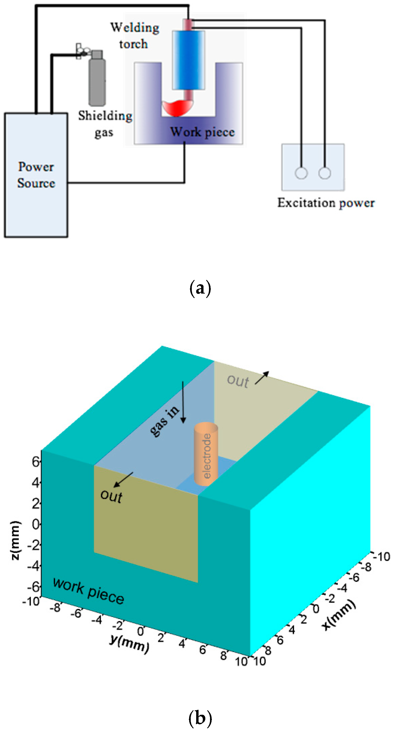
2.1. Computational Domain
2.2. Governing Equations
2.3. Boundary Conditions
2.3.1. Interior Boundary Conditions
2.3.2. External Boundary Conditions
2.4. Material Property and Solution Method
3. Results and Discussion
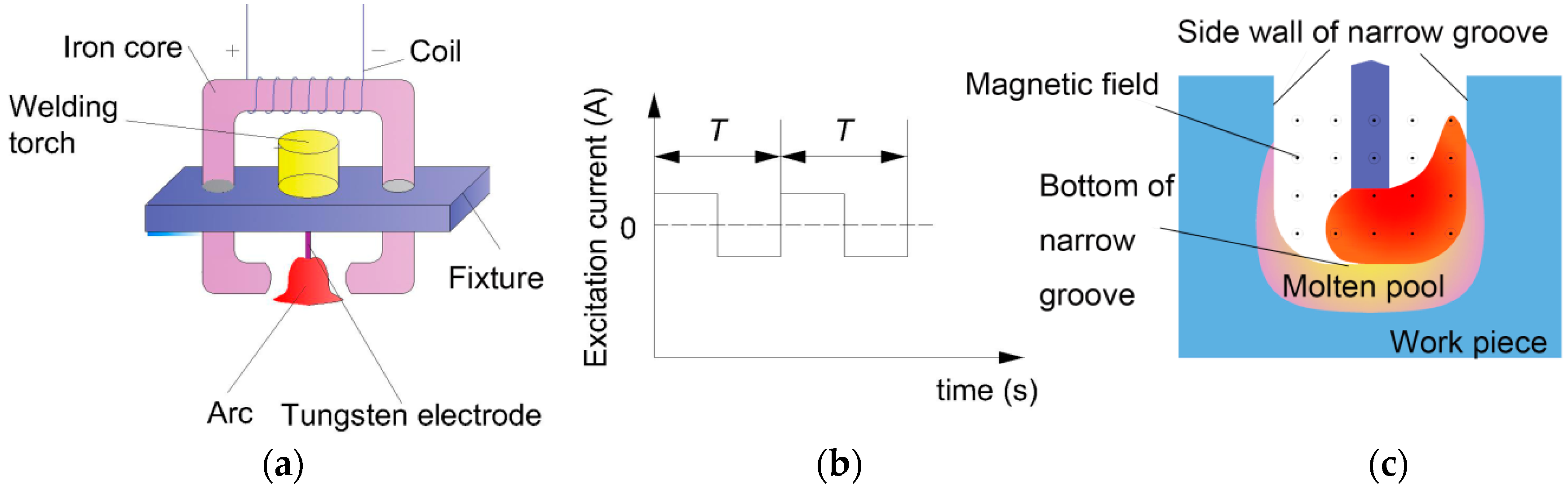
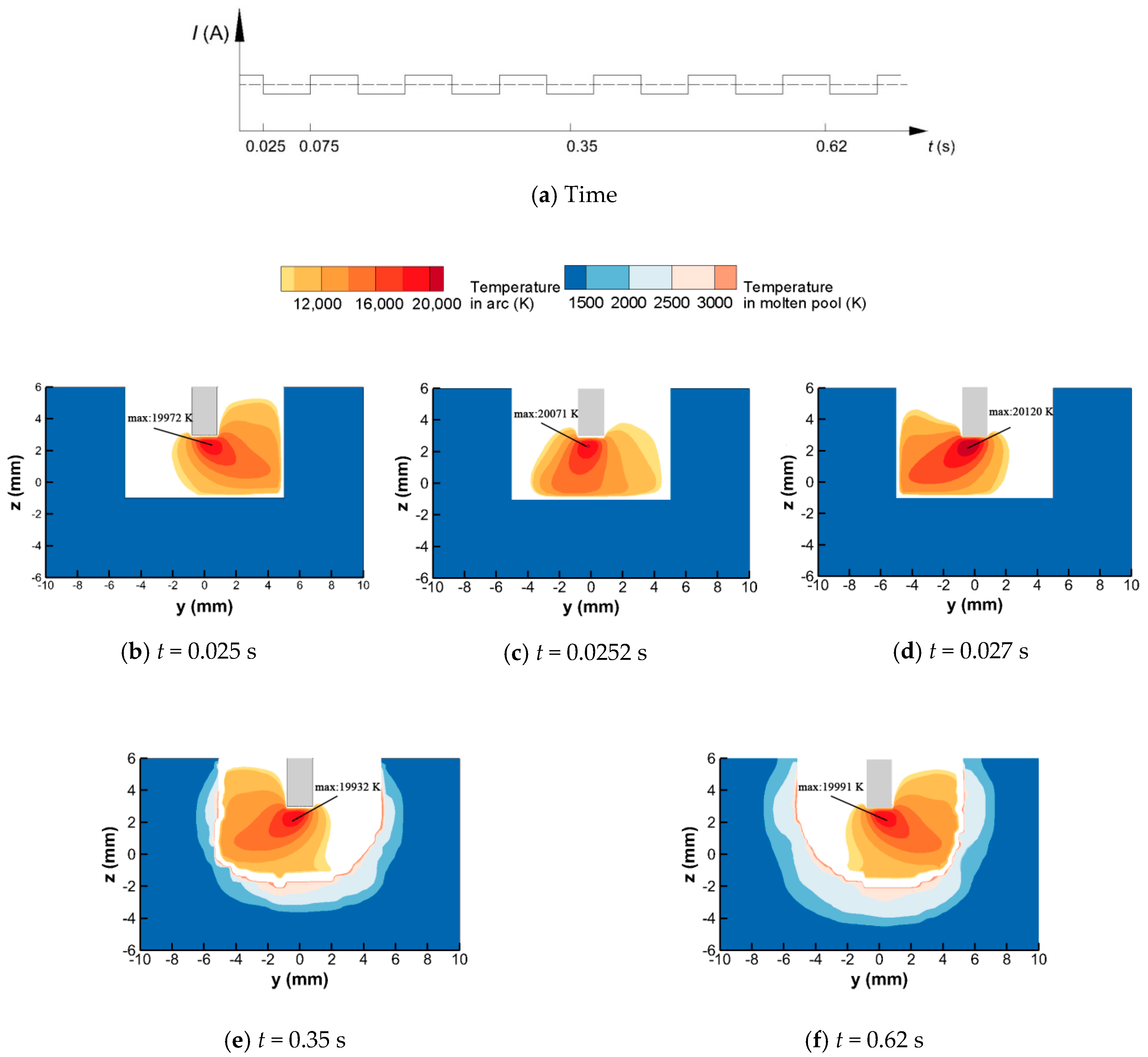
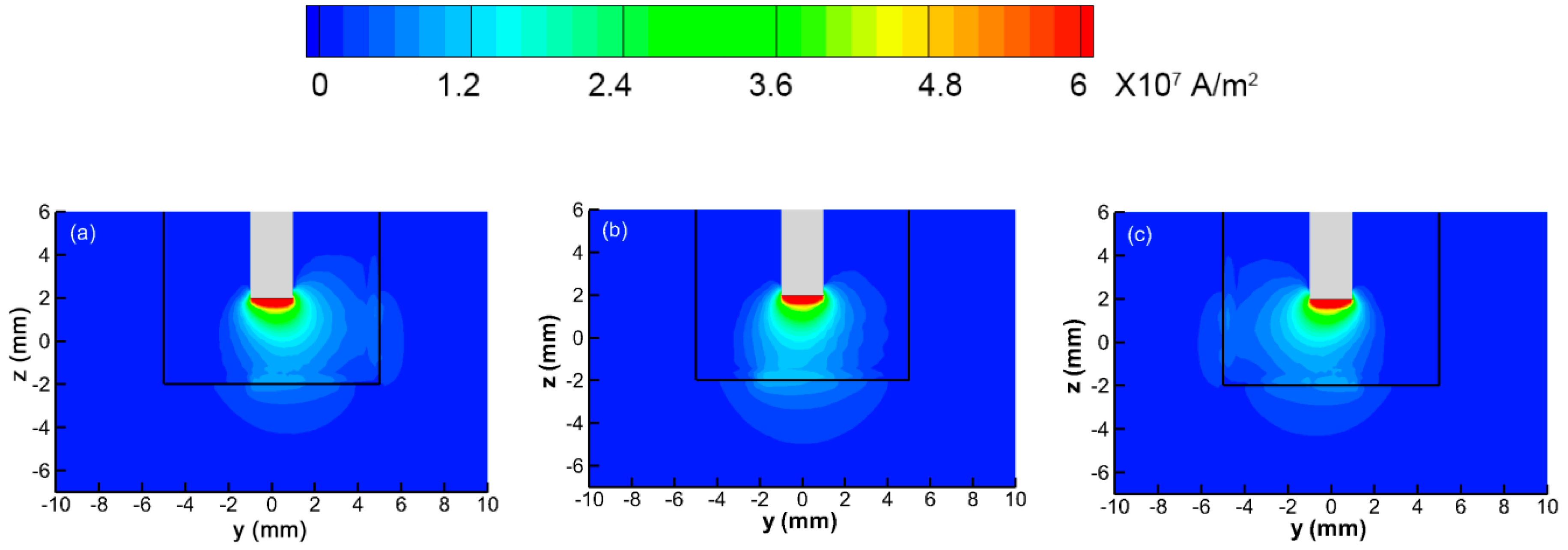
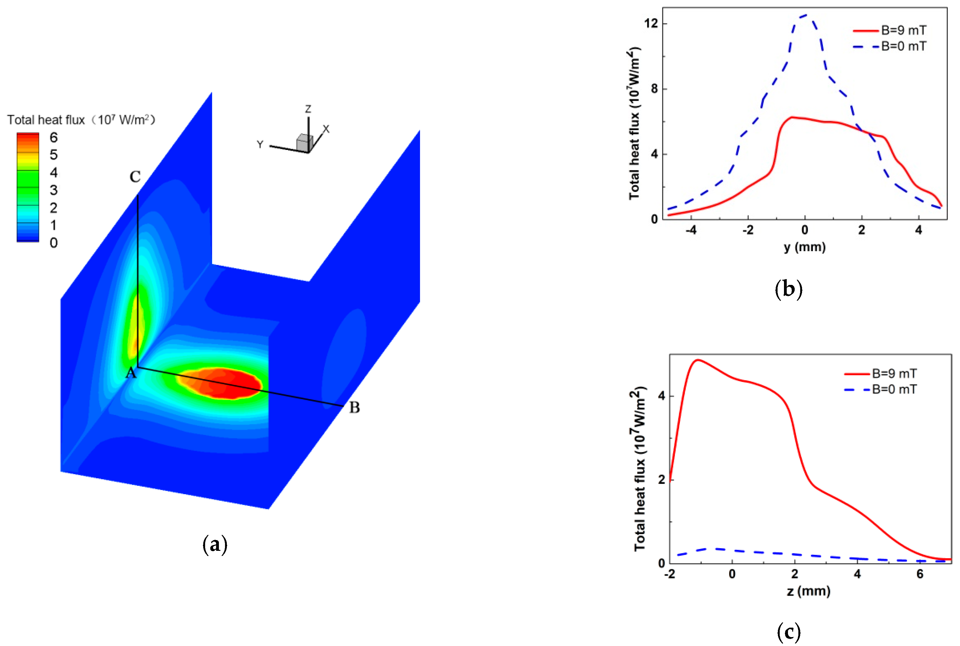
3.1. Behavior of the Magnetic Oscillation Arc
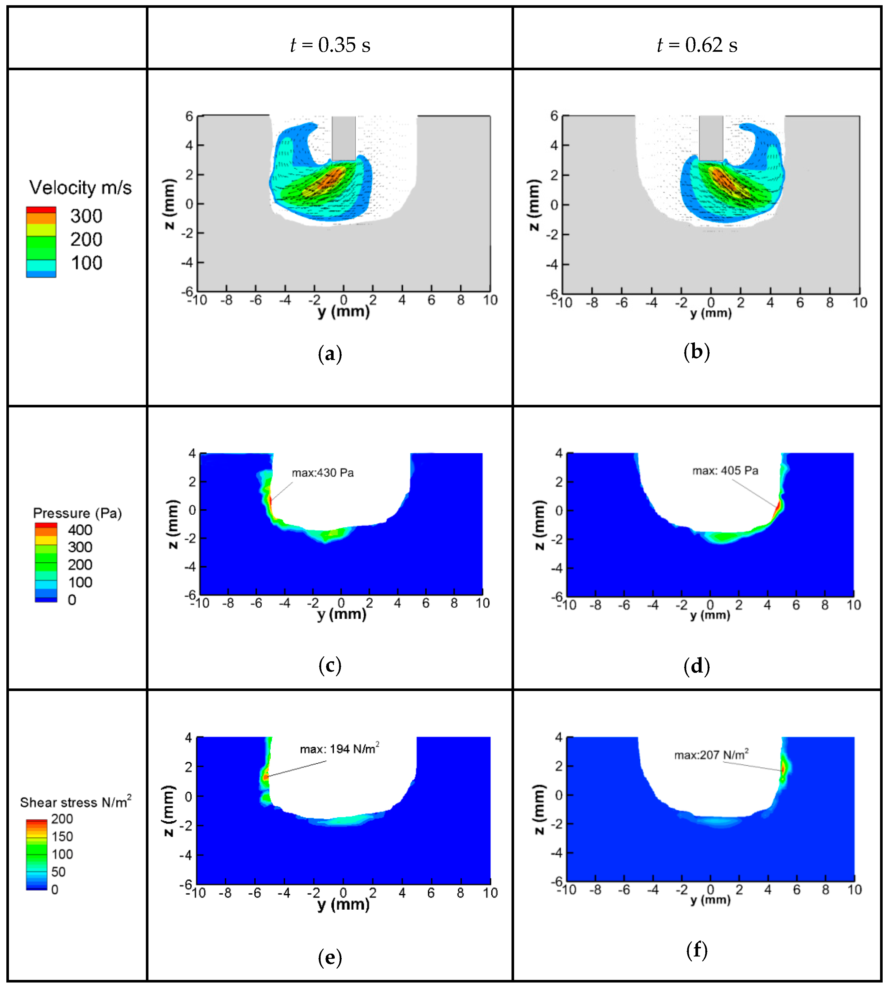
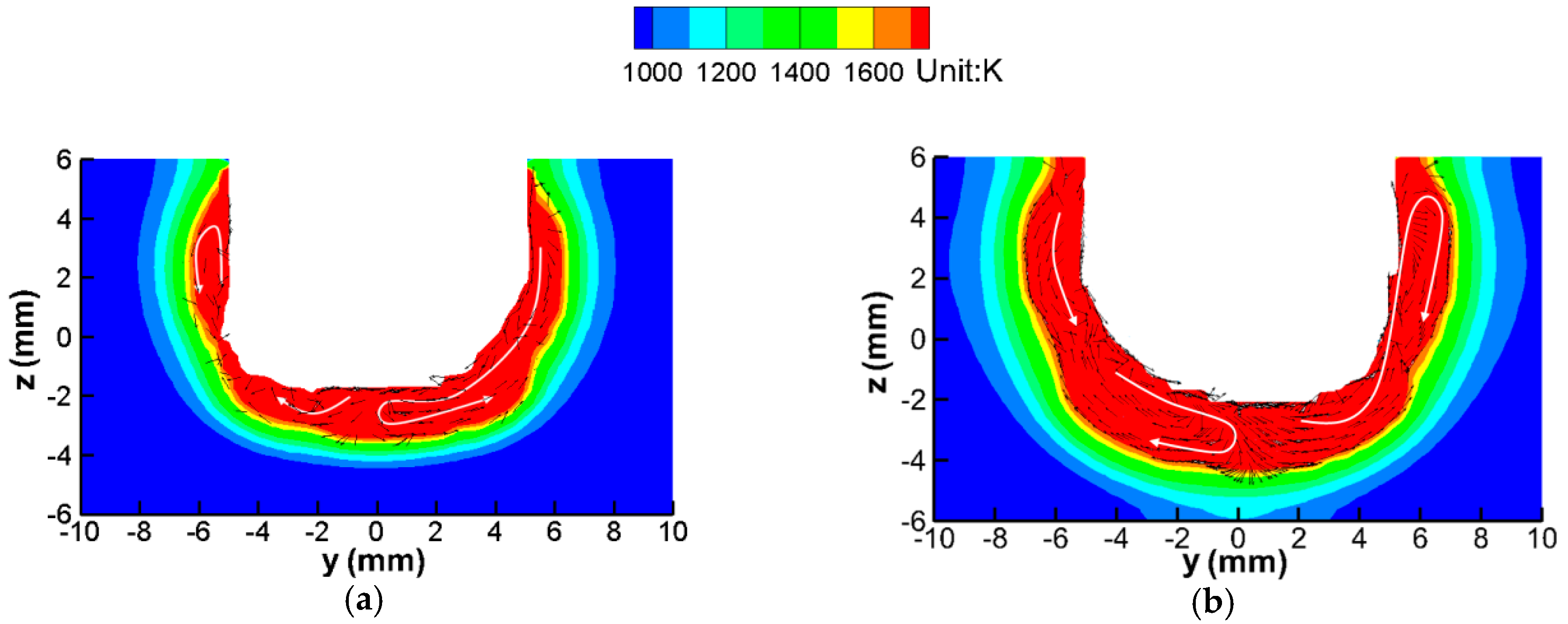
3.2. Fluid Flow of Molten Pool
3.3. Discussion
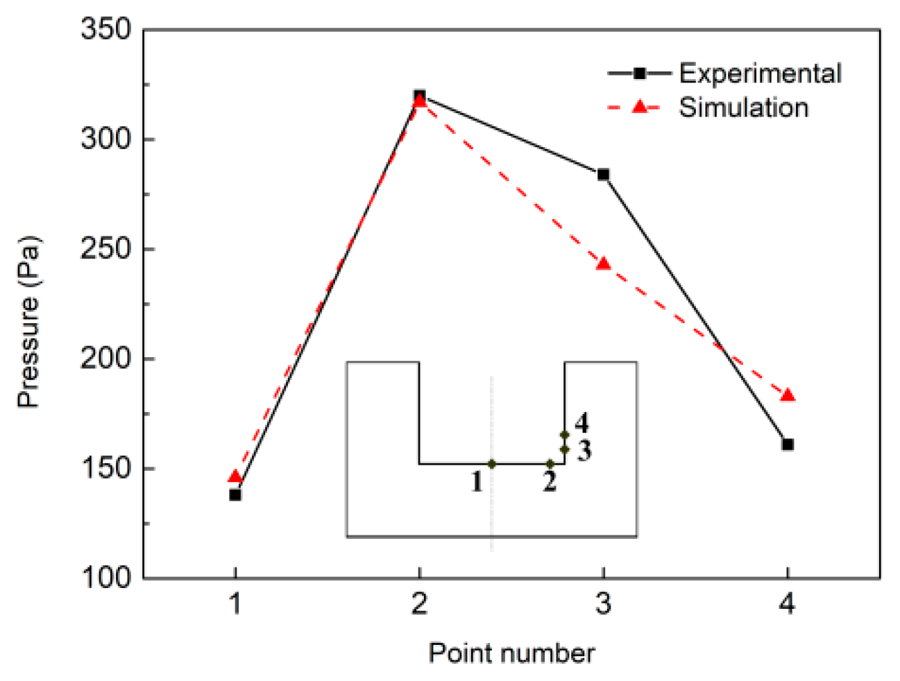
4. Validation of the Model
5. Conclusions
- (1)
- A unified mathematical model was developed for MOA-NG-GTA welding, including the magnetic oscillation arc, weld pool, the workpiece and the heat and mechanical coupling between them. The model was validated by comparison with the experimental results.
- (2)
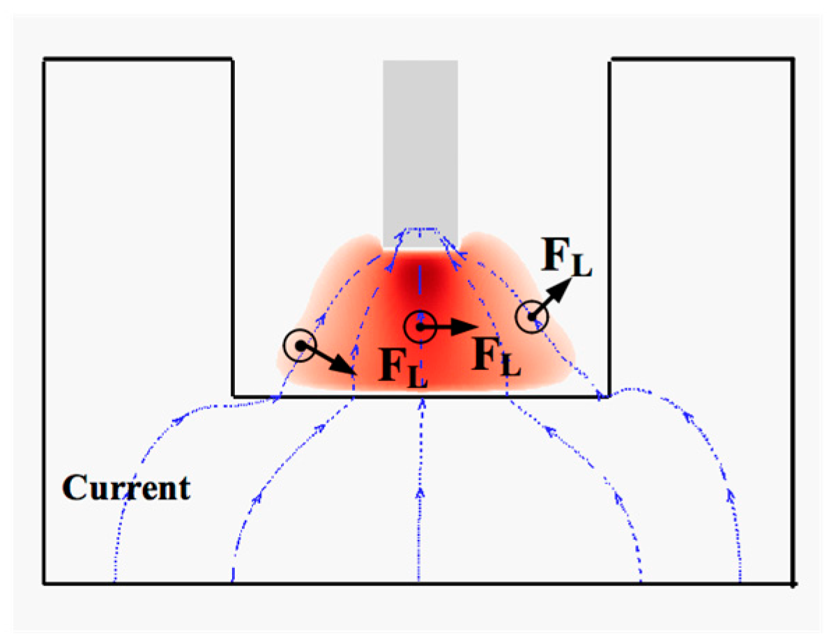
- The influence of the external alternating longitudinal magnetic field on the formation of welds was complicated. Although it was only added to the arc column, the current density of the welding zone, the heat flux and the forces along the pool surface were all changed, which affected the formation of the weld bead.
- (3)
- The prediction accuracy of the heat and mechanical properties of the deflecting arc had a key effect on the simulation of the weld formation. Thus, the factors that affected the welding arc will be considered in future work, such as the distribution of the external magnetic field and the metal vapor.
Author Contributions
Funding
Conflicts of Interest
References
- Huang, J.; Chen, H.; He, J.; Yu, S.; Pan, W.; Fan, D. Arrow gap applications of swing TIG-MIG hybrid weldings. J. Mater. Process. Technol. 2019, 271, 609–614. [Google Scholar] [CrossRef]
- Zhu, C.; Tang, X.; He, Y.; Lu, F.; Cui, H.; Mater, J. Effect of preheating on the defects and microstructure in NG-GMA welding of 5083 Al-alloy. J. Mater. Process. Technol. 2018, 251, 214–224. [Google Scholar] [CrossRef]
- Li, W.; He, C.; Chang, J.; Wang, J.; Wu, J. Modeling of weld formation in variable groove narrow gap welding by rotating GMAW. J. Manuf. Process. 2020, 57, 163–173. [Google Scholar] [CrossRef]
- Cai, X.Y.; Lin, S.B.; Fan, C.L.; Yang, C.L.; Zhang, W.; Wang, Y.W. Molten pool behaviour and weld forming mechanism of tandem narrow gap vertical GMAW. Sci. Technol. Weld. Join. 2016, 21, 124–130. [Google Scholar] [CrossRef]
- Liu, G.; Tang, X.; Hna, S.; Lu, F.; Cui, H. Influence of interwire angle on undercutting formation and arc behavior in pulsed tandem narrow-gap GMAW. Mater. Design. 2020, 193, 108795. [Google Scholar] [CrossRef]
- Li, W.; Yu, R.; Huang, D.; Wu, J.; Wang, Y.; Hu, T.; Wang, J. Numerical simulation of multi-layer rotating arc narrow gap MAG welding for medium steel plate. J. Manuf. Process. 2019, 45, 460–471. [Google Scholar] [CrossRef]
- Dong, B.; Cai, X.; Ni, Z.; Lin, S.; Fan, C.; Yang, C. Numerical simulation of arc characteristics in narrow gap TIG welding. Int. J. Mech. Sci. 2019, 105031, 161–162. [Google Scholar] [CrossRef]
- Meng, Y.; Li, G.; Gao, M.; Zhang, C.; Zeng, X. Formation and suppression mechanism of lack of fusion in narrow gap laser-arc hybrid welding. Int. J. Adv. Manuf. Technol. 2019, 100, 2299–2309. [Google Scholar] [CrossRef]
- Wang, J.; Zhu, J.; Zhang, C.; Xu, G.; Li, W. Effect of arc swing parameters on narrow gap vertical GMA weld formation. ISIJ Int. 2016, 56, 844–850. [Google Scholar] [CrossRef]
- Xu, G.; Wang, J.; Li, P.; Zhu, J.; Cao, Q. Numerical analysis of heat transfer and fluid flow in swing arc narrow gap GMA welding. J. Mater. Process. Technol. 2018, 252, 260–269. [Google Scholar] [CrossRef]
- Zhu, C.; Cheon, J.; Tang, X.; Na, S.J.; Cui, H. Molten pool behaviors and their influences on welding defects in narrow gap GMAW of 5083 Al-alloy. Int. J. Heat Mass Transfer. 2018, 126, 1206–1221. [Google Scholar] [CrossRef]
- Belous, V.Y.; Akhonin, S.V. Influence of controlling magnetic field parameters on weld formation in narrow gap argon-arc welding of titanium alloys. Paton Weld. J. 2007, 4, 2–5. [Google Scholar]
- Sun, Q.J.; Hun, H.F.; Li, W.J.; Liang, Y.C.; Feng, J.C. Electrode tips geometry and penetrating in narrow gap welding. Sci. Technol. Weld. Join. 2013, 18, 198–203. [Google Scholar] [CrossRef]
- Sun, Q.; Wang, J.; Cai, C.; Li, Q.; Feng, J. Optimization of magnetic arc oscillation system by using double magnetic pole to TIG narrow gap welding. Int. J. Adv. Manuf. Technol. 2016, 86, 761–767. [Google Scholar] [CrossRef]
- Belous, V.Y. Conditions for formation of defect-free welds in narrow-gap magnetically controlled arc welding of low titanium alloys. Paton Weld. J. 2011, 3, 16–18. [Google Scholar]
- Wang, J.; Sun, Q.; Zhang, T.; Zhang, S.; Liu, Y.; Feng, J. Arc characteristics in alternating magnetic field assisted narrow gap pulsed GTAW. J. Mater. Process. Technol. 2018, 254, 254–264. [Google Scholar] [CrossRef]
- Wang, J.; Sun, Q.; Feng, J.; Wang, S.; Zhao, H. Characteristics of welding and arc pressure in TIG narrow gap welding using novel magnetic arc oscillation. Int. J. Adv. Manuf. Technol. 2017, 90, 413–420. [Google Scholar] [CrossRef]
- Kang, Y.H.; Na, S.J. Characteristics of welding and arc signal in narrow groove gas metal arc welding using electromagnetic arc oscillation. Weld. J. 2003, 82, S93–S99. [Google Scholar]
- Wu, H.; Chang, Y.; Lu, L.; Bai, J. Review on magnetically controlled arc welding process. Int. J. Adv. Manuf. Technol. 2017, 91, 4263–4273. [Google Scholar] [CrossRef]
- Baskoro, A.S.; Fauzian, A.; Basalamah, H.; Kiswanto1, G.; Winarto, W. Improving weld penetration by employing of magnetic poles’ configurations to an autogenous tungsten inert gas (TIG) welding. Int. J. Adv. Manuf. Technol. 2018, 99, 1603–1613. [Google Scholar] [CrossRef]
- Wang, L.; Chen, J.; Wu, C. Numerical analysis of arc and droplet behaviors in gas metal arc welding with external compound magnetic field. J. Mater. Process. Technol. 2020, 282, 11638. [Google Scholar] [CrossRef]
- Liu, Z.; Li, Y.; Sun, Y. Simulation and analysis of heat transfer and fluid flow characteristics of arc plasma in longitudinal magnetic field-tungsten inert gas hybrid welding. Int. J. Adv. Manuf. Technol. 2018, 98, 2015–2030. [Google Scholar] [CrossRef]
- Xu, G.; Li, L.; Wang, J.; Zhu, J.; Li, P. Study of weld formation in swing arc narrow gap vertical GMA welding by numerical modeling and experiment. Int. J. Adv. Manuf. Technol. 2018, 96, 1905–11917. [Google Scholar] [CrossRef]
- Tanaka, M.; Terasaki, H.; Ushio, M.; Lowk, J.J. A unified numerical modeling of stationary tungsten-inert-gas welding process Metall. Mater. Trans. A 2002, 33, 2043–2052. [Google Scholar] [CrossRef]
- Ramírez, M.A.; Trapaga, G.; Mckelliget, J. A comparison between two different numerical formulations of welding arc simulation. Model. Simul. Mater. Sci. 2003, 11, 675–695. [Google Scholar] [CrossRef]
- Lowke, J.J.; Tanaka, M. ‘LTE-diffusion approximation’for arc calculation. J. Phys. D Appl. Phys. 2006, 39, 3634. [Google Scholar] [CrossRef]
- Hirt, C.W.; Nichols, B.D. Volum of fluid (VOF) method for two phase flow. J. Comput. Phys. 1981, 39, 449–468. [Google Scholar] [CrossRef]
- Brackbill, J.U.; Kothe, D.B.; Zemach, C. A continuum method for modeling surface tension. J. Comput. Phys. 1992, 100, 335–354. [Google Scholar] [CrossRef]
- Jian, X.; Wu, C.S.; Zhang, G.; Chen, J. A unified 3D model for an interaction mechanism of the plasma arc, weld pool and keyhole in plasma arc welding. J. Phys. D Appl. Phys. 2015, 48, 465504. [Google Scholar] [CrossRef]
- Murphy, A.B.; Arundell, C.J. Transport coefficients of argon, nitrogen, oxygen, argon-nitrogen, and argon-oxygen plasmas. Plasma Chem. Plasma Process. 1994, 14, 451. [Google Scholar] [CrossRef]
- Cram, L.E. Statistical evaluation of radiative power losses from thermal plasmas due to spectral lines. J. Phys. D Appl. Phys. 1985, 18, 401. [Google Scholar] [CrossRef]


| Boundary | T (K) | V (m/s) | Φ (V) | A |
|---|---|---|---|---|
| Gas Inlet | 500 | vx = vy = 0, vz = vg | ||
| Tungsten Electrode Tip | 3000 | - | ||
| Tungsten Surface | 1000 | - | ||
| Outlet | 1000 | - | 0 | |
| External Faces of the Workpiece | - | ϕ = 0 |
| Nomenclature (Symbol) | Value |
|---|---|
| Freezing Point (Tliquidus) | 1670 K |
| Melting Point (Tsolidus) | 1727 K |
| Density (ρ) | 7200 kg m−3 |
| Electric Wonductivity (σ) | 7.7 × 10⁵ S/m |
| Surface Tension Coefficient | 1.2 N m−1 |
| Surface Tension Temperature Gradient | 1 × 10⁻⁴ N m−1 K−1 |
| Work Function(φw) | 4.65 eV |
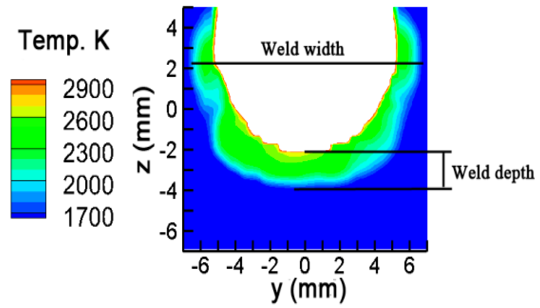
| Measure [6] | Prediction | Deviation | |
|---|---|---|---|
| Weld Width (mm) | 14.6 | 14.2 | 2.8% |
| Weld Depth (mm) | 2 | 1.8 | 8.7% |
Publisher’s Note: MDPI stays neutral with regard to jurisdictional claims in published maps and institutional affiliations. |
© 2020 by the authors. Licensee MDPI, Basel, Switzerland. This article is an open access article distributed under the terms and conditions of the Creative Commons Attribution (CC BY) license (http://creativecommons.org/licenses/by/4.0/).
Share and Cite
Jian, X.; Yang, X.; Li, J.; Wang, W.; Wu, H. Numerical Analysis of the Heating Characteristics of Magnetic Oscillation Arc and the Fluid Flow in Molten Pool in Narrow Gap Gas Tungsten Arc Welding. Materials 2020, 13, 5799. https://doi.org/10.3390/ma13245799
Jian X, Yang X, Li J, Wang W, Wu H. Numerical Analysis of the Heating Characteristics of Magnetic Oscillation Arc and the Fluid Flow in Molten Pool in Narrow Gap Gas Tungsten Arc Welding. Materials. 2020; 13(24):5799. https://doi.org/10.3390/ma13245799
Chicago/Turabian StyleJian, Xiaoxia, Xing Yang, Jingqian Li, Weihua Wang, and Hebao Wu. 2020. "Numerical Analysis of the Heating Characteristics of Magnetic Oscillation Arc and the Fluid Flow in Molten Pool in Narrow Gap Gas Tungsten Arc Welding" Materials 13, no. 24: 5799. https://doi.org/10.3390/ma13245799
APA StyleJian, X., Yang, X., Li, J., Wang, W., & Wu, H. (2020). Numerical Analysis of the Heating Characteristics of Magnetic Oscillation Arc and the Fluid Flow in Molten Pool in Narrow Gap Gas Tungsten Arc Welding. Materials, 13(24), 5799. https://doi.org/10.3390/ma13245799