1. Introduction
Bamboo has been utilized as a prominent construction material in buildings for centuries. Recent trends in using sustainable material for building development is reigniting the interest in natural construction materials. Bamboo can be used as a reliable and sustainable alternative to conventional materials in construction based on two key attributes—namely, a high strength-to-weight ratio, and an unrivalled growth rate of up to 100 cm per day [
1,
2,
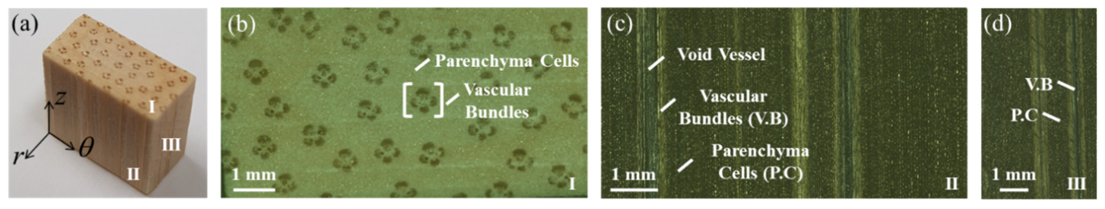
3]. Bamboo morphology has developed into a of smart hollow structure consisting of nodes and internodes which provide the structural framework to support the weight of its uppermost section. As a natural composite, it inherits a high strength-to-weight ratio from a hierarchically arranged microstructure composed of concentrated fibers known as a vascular bundle. The axially strong fibers consist of cellulose microfibrils held in a parenchyma matrix composed of hemicellulose and lignin, as shown in
Figure 1. Furthermore, the volume fraction of vascular bundles increases with height to compensate for the inferior strength of the uppermost section due to the reduced wall thickness. This inhomogeneous structure enables bamboo to withstand extreme flexural loading caused by wind and snow [
1,
4,
5].
As a natural material, the strength and durability of bamboo depends on several factors such as species, maturity, treatment and loading conditions [
6]. In construction, the influence of external loading conditions on its strength has high structural implications. Due to its inhomogeneous material characteristics, bamboo displays a complex fracture behavior. Numerous experimental investigations, conducted on deformation behavior due to bending load, have shown mixed failure modes [
7,
8,
9,
10,
11]. The failure modes differed in terms of crack initiation and propagation in comparison to other external loading conditions such as compression, shear and torsion conditions as reported in other studies [
10,
12,
13,
14,
15].
From a fractography analysis, the low interfacial strength reported in bamboo was found to enhance its transverse toughness [
16]. The weakened interfacial strength in bamboo, which accounts for its high fracture toughness, is offset by the node and by the optimally distributed microstructure in its cross-section [
17]. The resistance against crack propagation parallel to grain, which was governed by interfacial strength, was found to be lower in the outer as opposed to the inner layer [
18]. Its inner fibers were found to possess higher toughness as they displayed most of the crack bridging [
19,
20]. Bamboo was able to absorb greater energy during the large bending deformation of culms [
18,
21,
22,
23].
The complex shape and inherent material variability in bamboo poses a major challenge to precisely determine and establish the fracture criterion of full-scale bamboo culm by experimental methods. Numerical methods such as the finite element method (FEM) has an advantage in terms of overcoming the material constraints in bamboo and is an excellent tool to probe further into its mechanical behavior [
24]. FEM simulations of full-scale bamboo culm were mainly conducted for the assessment of material limitations and their failure modes under various loading conditions and secondly for a reliability and performance assessment of individual members in complex framework structures [
12,
24,
25,
26,
27,
28].
Even though the fracture toughness of the microscopic structure of bamboo has been investigated in the past [
18,
19,
29,
30,
31], the effect of material inhomogeneity and unique geometrical attributes on its macroscopic fracture mechanisms remain unexplored to this date to the author’s knowledge. Thus, in this study, the aim is to investigate the effect of material composition and geometrical attributes on the fracture mechanisms of bamboo in various modes of loading by FEM. The results of this study are significant and can be applied to a bamboo-inspired bionic design, which has great prospects for improving the strength in advanced composites [
32,
33]. By biomimicking the naturally optimized structure of bamboo, artificially optimized structure in complex composites, consisting of axially reinforced fibers and similar macrostructural attributes to bamboo, can be achieved.
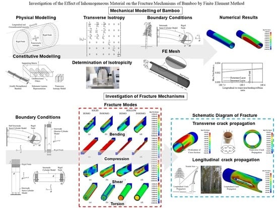
2. Mechanical Modelling of Bamboo
Bamboo exhibits a high longitudinal-to-transverse bending stiffness ratio which improves its ability to resist externally imposed bending loads. Akin to many other biological structures such as tree trunks, avian and mammalian bones, bamboo’s structure is also optimized to the loading conditions it is subjected to by having an adaptive geometry coupled with an optimally distributed material [
24]. This enables smooth deformation in bamboo unique geometry in accordance with the stress- or strain-dependent requirements. In the first part of the study, the optimized transverse isotropy developed in bamboo culm to resist bending deformation was determined numerically by FEM.
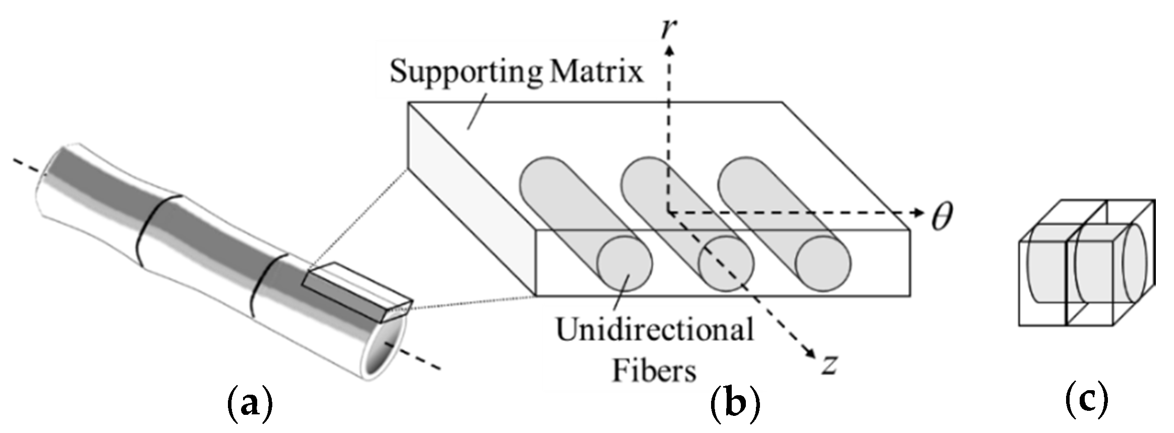
2.1. Physical Modelling
A representation model of bamboo is needed to analyze its fracture mechanisms since real bamboo has complex characteristics due to species, origin, maturity and moisture content among others. Here, three assumptions for bamboo structure are adopted to analyze the fracture mechanisms with respect to fiber direction. The schematic representation of the assumptions made on the material model, material structure and geometry are shown in
Figure 2.
Bamboo behaves non-linearly in conditions of humidity exceeding 60% and linearly in conditions of humidity less than 40% [
12]. Non-linear behavior is also widely observed in engineered bamboo [
34]. In construction, the linear elastic behavior of bamboo elements is assessed by the seismic response coefficient which accounts for the energy dissipation capacity in bamboo structures [
35]. In this study, the linear elastic body was assumed as a constitutive model to clarify the fracture behavior of bamboo [
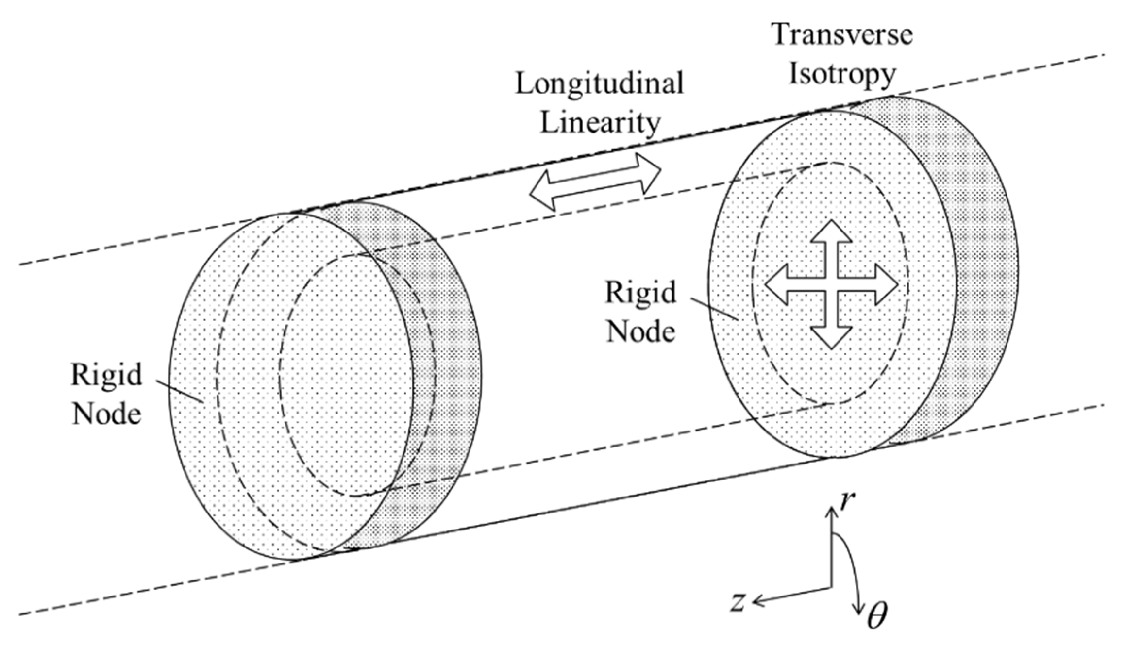
35]. Secondly, the axially strengthened bamboo fibers composed of cellulose microfibrils held in a matrix of hemicellulose and lignin was simplified by assuming a transversely isotropic model [
36].
The microstructure of bamboo nodes consists of thickened vascular bundles which are arranged in an interweaving pattern [
17]. The nodes in bamboo structure have significant structural importance as they improve the lateral stability and stiffness of slender sections and provide additional support to prevent failure by local buckling in the bamboo culm. Therefore, in this study, the node section, which also represents the undeformed remaining upper section of the bamboo structure, was considered as the strongest part in the bamboo culm and hence modelled as a solid rigid section [
7,
37,
38]. The fracture in the bamboo structure was analyzed and discussed by considering unit-internode modelling to reduce the computational time [
37].
2.2. Constitutive Modelling
2.3. Determination of Optimized Transverse Isotropy
In this section, the transverse elastic modulus ET was determined numerically on LS-DYNA (Livermore Software Technology, Livermore, CA, USA), an FEM software, by investigating the optimized transverse isotropy developed in bamboo culm to resist bending loads. A numerical simulation was conducted in implicit mode and the maximum principal strain criterion, which is one of the fundamental criteria to evaluate material failure, was adopted to analyze the deformation behavior.
2.3.1. Material Parameters
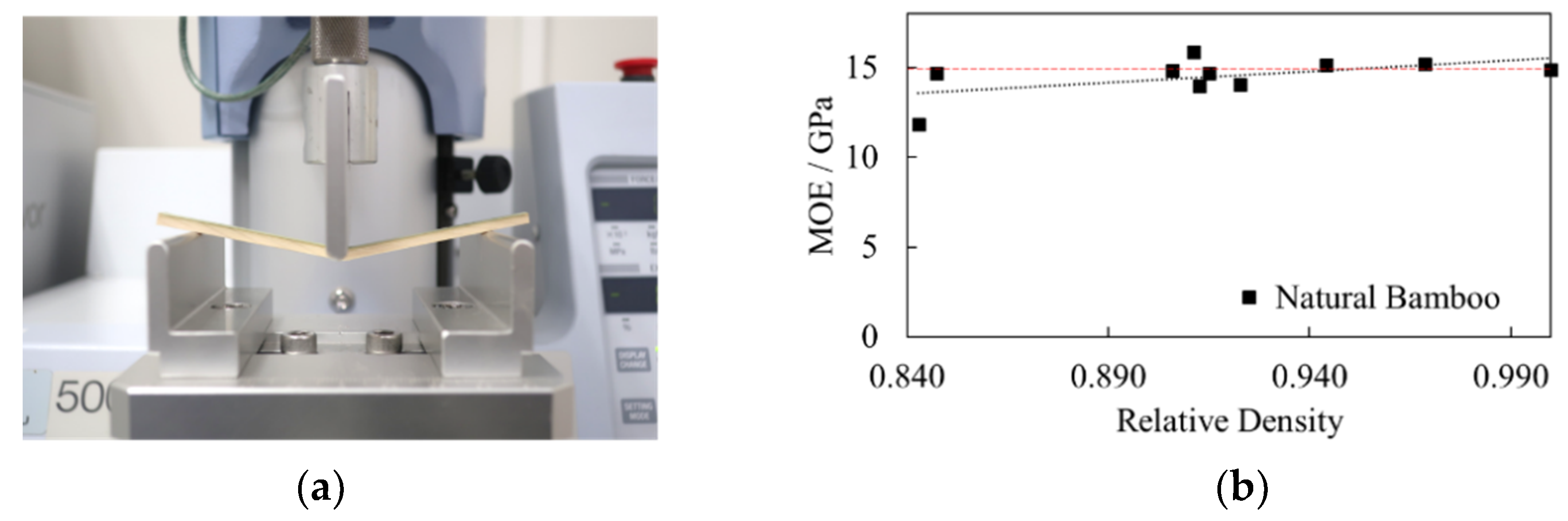
The first consideration in material constants is the noticeable orthotropic characteristics which prevail in the axial direction of bamboo. The elastic modulus
EL was experimentally determined by evaluating small clear specimens of Madake bamboo (
Phyllostachys bambusoides) with average dimensions of 100 mm (longitudinal) × 8 mm (tangential) × 3 mm (radial) in a 3-point bending test on a Shimadzu EZ-S table-top universal testing instrument (Shimadzu Corporation, Kyoto, Japan) as shown in
Figure 4a. A total of 10 specimens of natural Madake bamboo were evaluated. The cross-head speed and distance between supports were set at 2 mm/min and 80 mm, respectively, and the supports and punch had radii of 2.5 mm. Tests were conducted in a controlled environment at a temperature of 25 °C and relative humidity below 20%. An average modulus of elasticity (MOE)
EL of 15 GPa was obtained from experiment, as shown in
Figure 4b.
Secondly, bamboo was simplified into a transversely isotropic model. The corresponding longitudinal-to-transverse bending stiffness ratio (
EL-
ET) of this model was initially considered as 100:1 based on past literature data, which reported the longitudinal and transverse stiffness components of bamboo to be less than the mentioned ratio [
10,
40,
43,
44]. The material constants in the radial and tangential directions were considered as equal (
ET) which was also the case in previous studies [
12,
38].
ν
L was determined from past literature data as 0.3 while ν
T was calculated based on the following orthotropic symmetry condition [
25]:
Additionally, in transversely isotropic material, ν
L and ν
T must obey the following relations:
G
L was determined based on the following relation:
Since the transverse properties of a transversely isotropic material are not independent, G
T was determined from the following expression:
To compare the deformation behavior of the inhomogeneous structure with other material characteristics, an isotropic material model with elastic properties was considered. In this study, the isotropic model was simply referred to as homogeneous model. The density of both material models was set to 700 kg/m
3 [
45] and their engineering constants are displayed in
Table 1.
2.3.2. Geometrical Modelling and Boundary Conditions
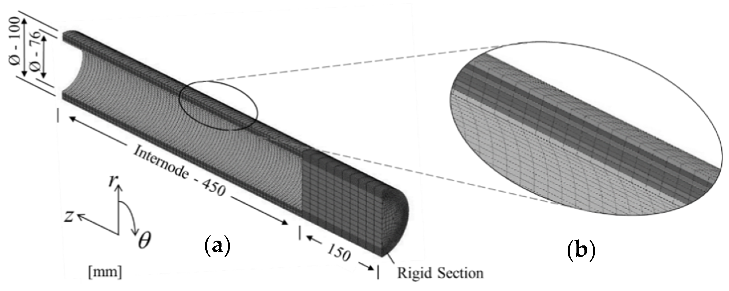
The physical model was constructed based on morphological data of Madake bamboo. Hence, for an internode count of 18, an outer diameter, wall thickness and intermodal length of 100, 12 and 450 mm, respectively, were considered [
1]. To curtail the computational time, a half-solid cylindrical model was opted to simulate the hollow bamboo structure and, as per the third assumption, the node was assumed as a solid rigid section. The rigid section was assigned with elastic material data.
The optimized transverse isotropy was investigated in bending mode as bamboo is naturally adapted to resist bending loads, as shown in
Figure 5a. The boundary conditions of the bending mode are shown in
Figure 5b. The bending behavior was simulated by applying a localized displacement δ of 5 mm, aligned with the fiber direction, at the bottom corner of the rigid section, as shown in
Figure 5b. A node constraint in the radial direction was applied at the neutral axis of the node-internode intersection. At the wall end, movement was restricted in the z-direction only.
2.3.3. FE Mesh
The model was designed on a finite element modelling and postprocessing software (FEMAP) (Siemens Digital Industries Software, Plano, TX, USA), and a hexahedral mesh solid was applied. The meshed domain was discretized into 53,951 nodes and 47,100 elements with finer mesh at the internode section, as displayed in
Figure 6a.
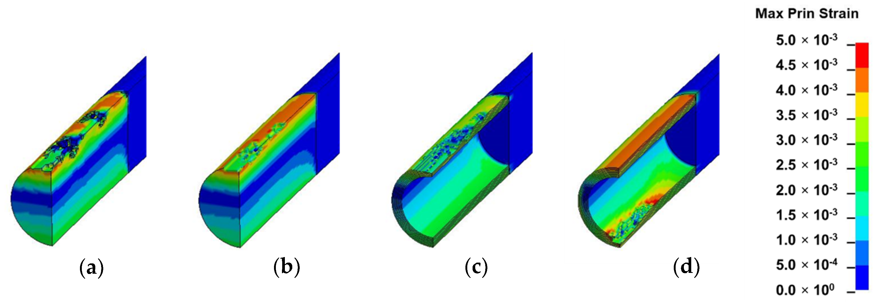
2.3.4. Numerical Results and Analysis
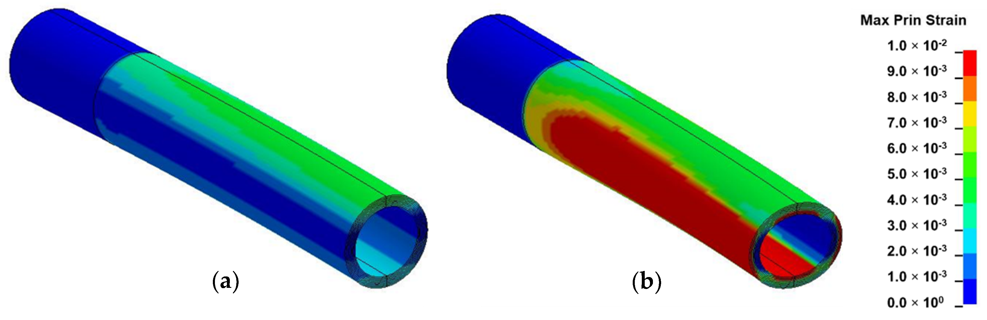
From the numerical results of
Figure 7, distinct variation in the circumferential distribution of maximum principal strain was observed between the two material models. As shown in
Figure 7a, the original shape of the homogeneous model was found to be preserved as the highest maximum principal strain occurred on its outermost convex section. In contrast to
Figure 7b, the highest maximum principal strain distribution in the inhomogeneous model was observed at alternate locations, namely at the neutral axis of the outermost surface and at the inner surface of both convex and concave sides.
Furthermore, the ovalization observed in this material model occurred by inward forces which were generated by longitudinal tensile and compressive strains on convex and concave sides, respectively, during bending. This deformation mode was found to correspond to the natural failure observed in bamboo [
7,
8,
9]. In nature, ovalization is assumed to be more pronounced midway along culm length where the intermodal length reaches a maximum value [
1].
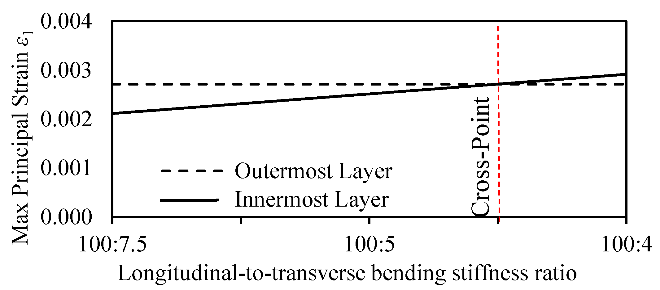
The resistance to bending deformation by the innermost and outermost layers was further analyzed (as shown in
Figure 8) to reveal the optimized longitudinal-to-transverse bending stiffness ratio developed in bamboo culm. The maximum principal strain ε
1 distribution in the inner and outer layers were plotted against a varying longitudinal-to-transverse bending stiffness ratio.
From
Figure 8, the analysis of results revealed the occurrence of a simultaneous mixed mode of failure at a longitudinal-to-transverse bending stiffness ratio of 100:4.5. The dotted line at this ratio indicates the cross-point at which both innermost and outermost layers have equal resistance to bending deformation. The equal distribution of deformation resistance between the innermost and outermost layers is assumed to provide bamboo with an optimized structure adapted to withstand high external loadings. Beyond the highlighted point, a shift in maximum deformation is observed from the outermost layers to the innermost layers. The reduction in the transverse strength of the inhomogeneous model accounts for the extra bending toughness observed in bamboo culms during bending.
The optimized longitudinal-to-transverse bending stiffness ratio of 100:4.5 corresponds to actual ratio prevailing between the experimental values of MOE in full-culm bamboo ranging between 20–15 GPa axially and 0.8–0.5 GPa transversely, respectively [
10,
40,
43,
44]. As reported by Xu, the transverse tensile strength in orthotropic natural materials ranges between 1/50 and 1/24 of the longitudinal tensile strength due to a significant difference in chemical bond energy as cellulose chain molecules are connected by C–C and C–O axially and by C–H and H–O radially [
46]. As a bamboo shoot emerges from the ground, its growth is restricted to the longitudinal direction, as can be observed from its microstructure in
Figure 1 due to the absence of cambium [
7], hence deriving its strength predominantly in the axial direction. Thus, bamboo has adapted to its natural environment by developing an optimized structure at multiple length scales to withstand external forces [
38].
3. Investigation of Fracture Mechanisms
Bamboo exhibits a complex deformation behavior when exposed to external loading conditions as a result of its inhomogeneous nature [
7,
8,
9,
10,
12,
13,
14,
15]. In this section, the bamboo model incorporated with transverse isotropic material was simulated in FEM in external loading conditions, namely bending, compression, shear and torsion modes to investigate its fracture mechanisms.
3.1. Fundamental Loading Modes
The simulation of the fundamental loading modes was conducted on LS-DYNA in implicit mode. To investigate crack initiation stage and propagation in each mode of loading, an element erosion technique was implemented. The maximum principal stress and strain criteria were found to be more applicable to assess failure in hard and brittle materials in comparison to ductile ones [
47]. Being a hard material, bamboo often exhibits brittle failure which is characterized by sudden split followed by instantaneous crack propagation. The maximum principal strain criterion has previously been used to investigate the failure mechanism in engineered bamboo and timber materials [
48], while the maximum principal stress criterion has been considered to investigate the mechanical deformation behavior in bamboo culm sections [
12,
25]. In this study, the maximum principal strain at failure, ε
max, was adopted as the failure criterion in the element erosion setting. The ε
max criterion, corresponding to fracture initiation by element erosion, was defined as 30% less than the value of the maximum principal strain.
3.1.1. Material Parameters
The corresponding engineering constants of the optimized longitudinal-to-transverse isotropic ratio determined in
Section 2.3.4 are displayed in
Table 2. The fracture behavior of this inhomogeneous material model was compared with one of homogeneous material characteristics comprising elastic properties, as indicated in
Table 1.
3.1.2. Geometrical Modelling and Boundary Conditions
The geometrical models were constructed based on morphological data of Madake bamboo, as in
Section 2.3.2, and were effectively refined according to their mode of loading to minimize computational time [
1]. A full intermodal length of 450 mm was selected for the bamboo model in compression, torsion and shear modes while a half-length of 225 was selected in the bending mode. A semi-cylindrical model was considered in bending and shear investigations, while full cylindrical and quarter cylindrical models were considered in torsion and compression investigations, respectively. The node was assumed as a full solid with a rigid section 75 mm in length in all simulations except in bending and shear investigations whereby a length of 150 mm was considered.
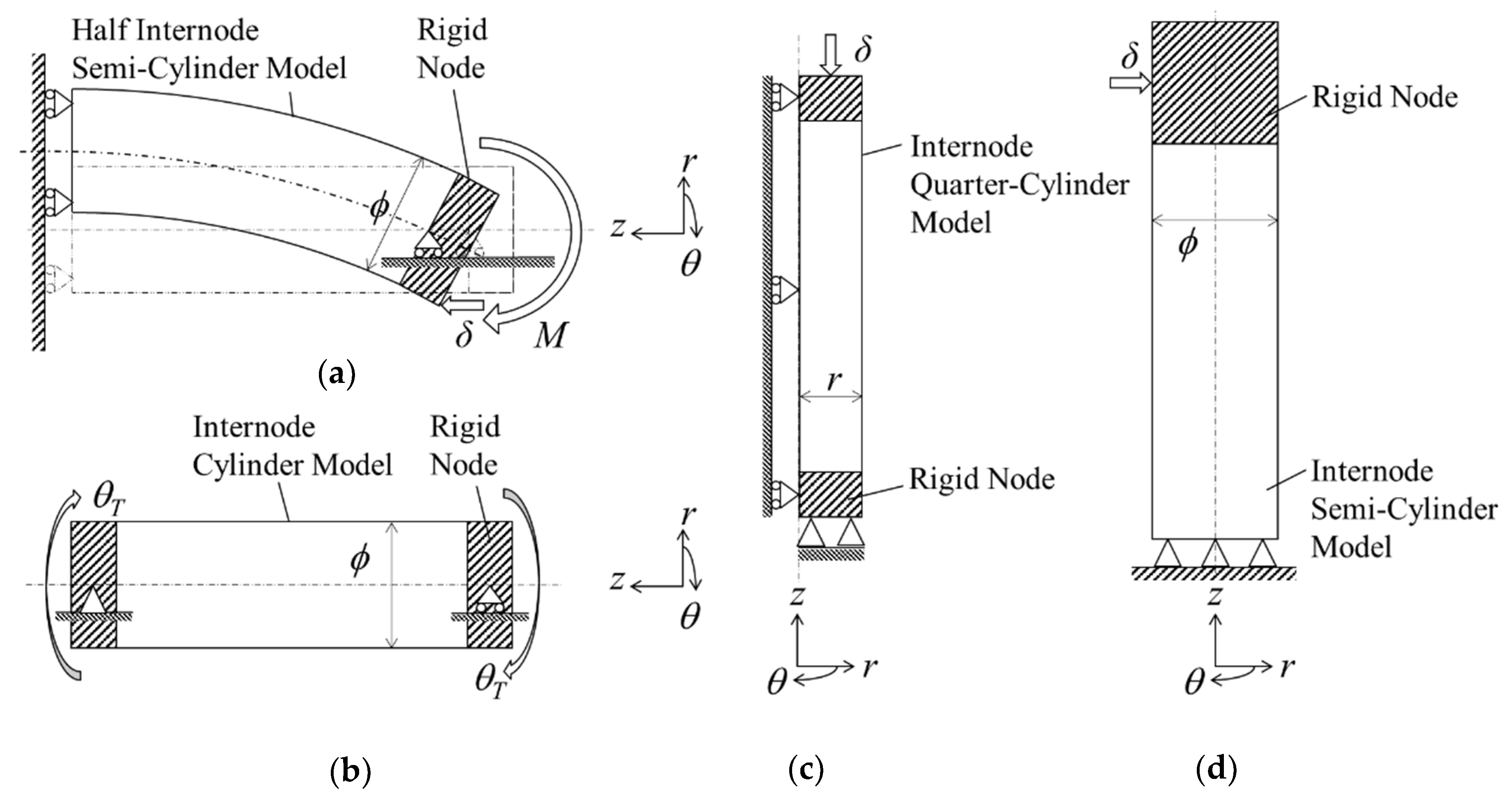
Specific boundary conditions were applied to each loading mode, as shown in
Figure 9. Firstly, constraints perpendicular to the sliced plane were applied to each model to replicate symmetrical sections. Secondly roller supports were applied at the wall end in bending mode while pin supports were applied at the fixed end in compression and shear modes. Thirdly, deformation was simulated by applying a displacement
δ of 5 mm in bending, compression and shear modes, while an equivalent circumferential displacement in terms of torsion angle θ
T of 5.73° was applied in torsion mode.
3.1.3. FE Mesh
For the purpose of comparing FEM results of bamboo-model, four models were considered in each mode of loading and designing on FEMAP. These were (1) solid-homogeneous, (2) solid-inhomogeneous, (3) hollow-homogeneous and (4) hollow-inhomogeneous models. A hexahedral mesh solid was applied throughout all models and a finer mesh of the discretized domain was concentrated at the internode section.
3.2. Strain Field Analysis
In this section, the results of each loading mode are presented and discussed based on
Figure 10,
Figure 11,
Figure 12 and
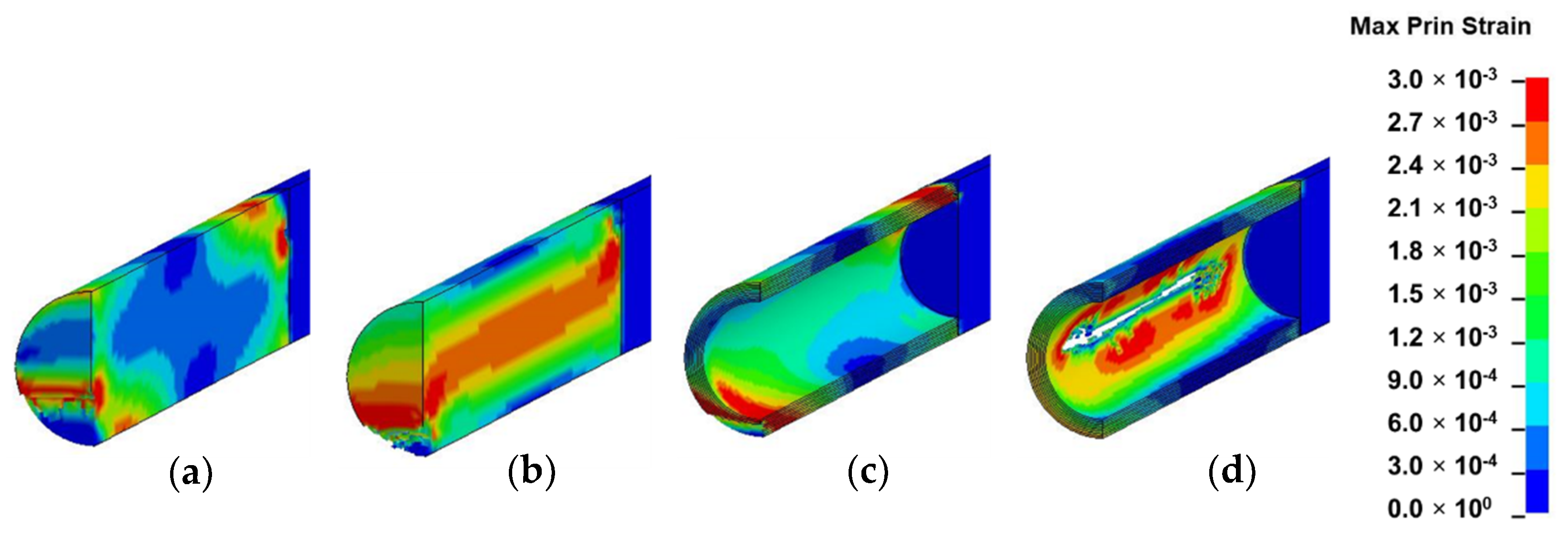
Figure 13. The location of crack initiation and the mode of propagation differed significantly as a result of variations in geometry, material property and mode of loading. In solid models, the location of crack initiation in bending, torsion and shear modes of loading were to a large extent similar regardless of material variation. For instance, both solid-type models in shear mode (
Figure 13a,b) exhibited break point crack initiation replicating a brittle fracture typically observed in hard solid materials. A notable difference in the compression loading mode of the solid-inhomogeneous model (
Figure 11b) was observed as cracks were found to initiate closer to the internode midsection.
The following key observations were made from each mode of loading of the hollow-inhomogeneous model. In bending mode, cracks, which initiated from the lower innermost wall section of the culm, propagated in a longitudinal and radially outward direction in a splitting-like pattern. In the compression mode, cracks originated simultaneously from the outermost wall of the node-internode sections. They followed a diagonal pathway towards the middle of the internode and moved radially inwards. In the torsion mode, however, crack initiation was only observed at the outermost wall section of the prescribed end. Subsequent propagation affected the outermost wall section followed by the node-internode section of the fixed end. Radial penetration was observed at both ends. In the shear mode, a crack was observed to be initiated at the innermost wall of the internode middle section. The crack propagated radially outwards in a splitting-like pattern.
3.3. Analysis of Bamboo Fracture Mechanisms
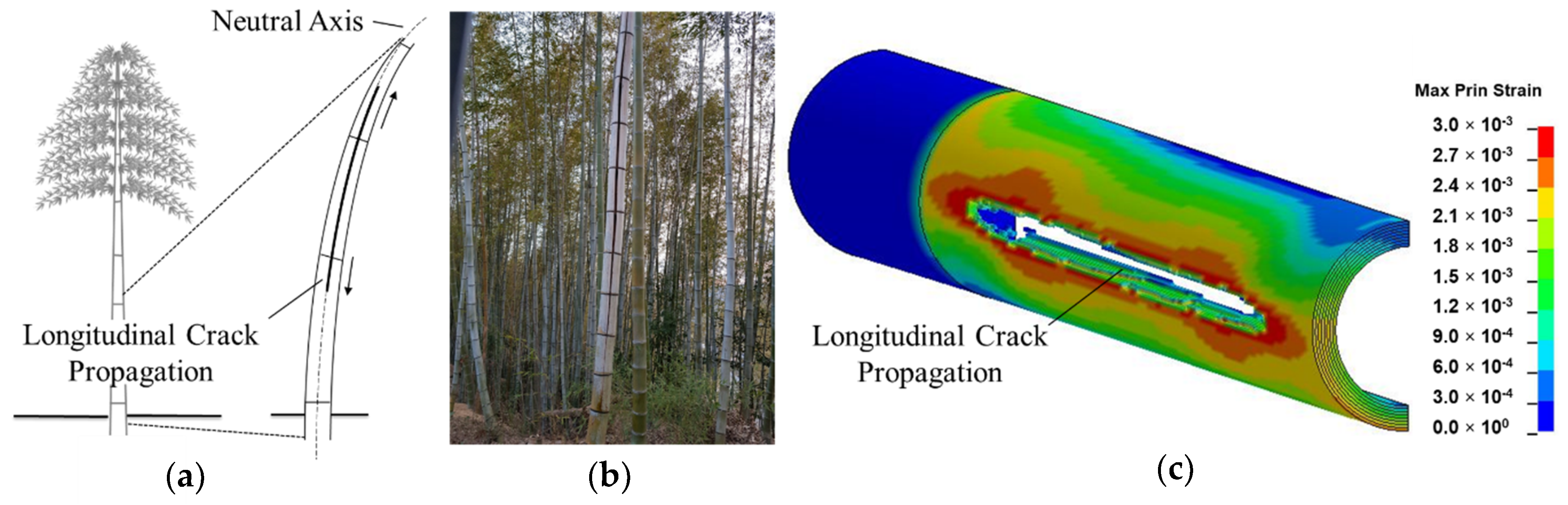
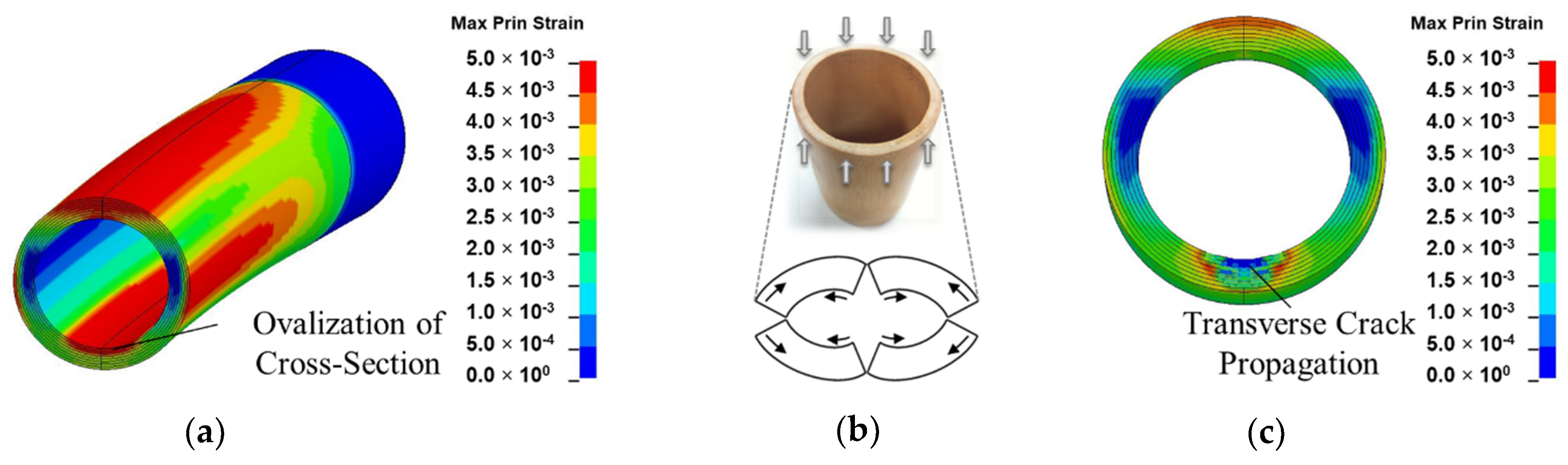
3.3.1. Bending
In bending, the crack initiation at the bottom inner wall section of the inhomogeneous culm model is assumed to be related to cross-sectional flattening as a result of poor transverse strength. Cross-sectional flattening corresponds to the deformation theory of tubular section during bending by Brazier’s effect. It is caused by inward forces which are induced by longitudinal tensile and compressive stresses on the convex and concave sections, respectively, and have a tendency to ovalize the cross-section [
7,
8,
9,
49]. As deformation is accentuated, ovalization leads to cracking at four vertices, as shown in
Figure 14b [
44,
50]. Splitting also arises in the compressive region of the culm section as fibers are crushed during bending [
10].
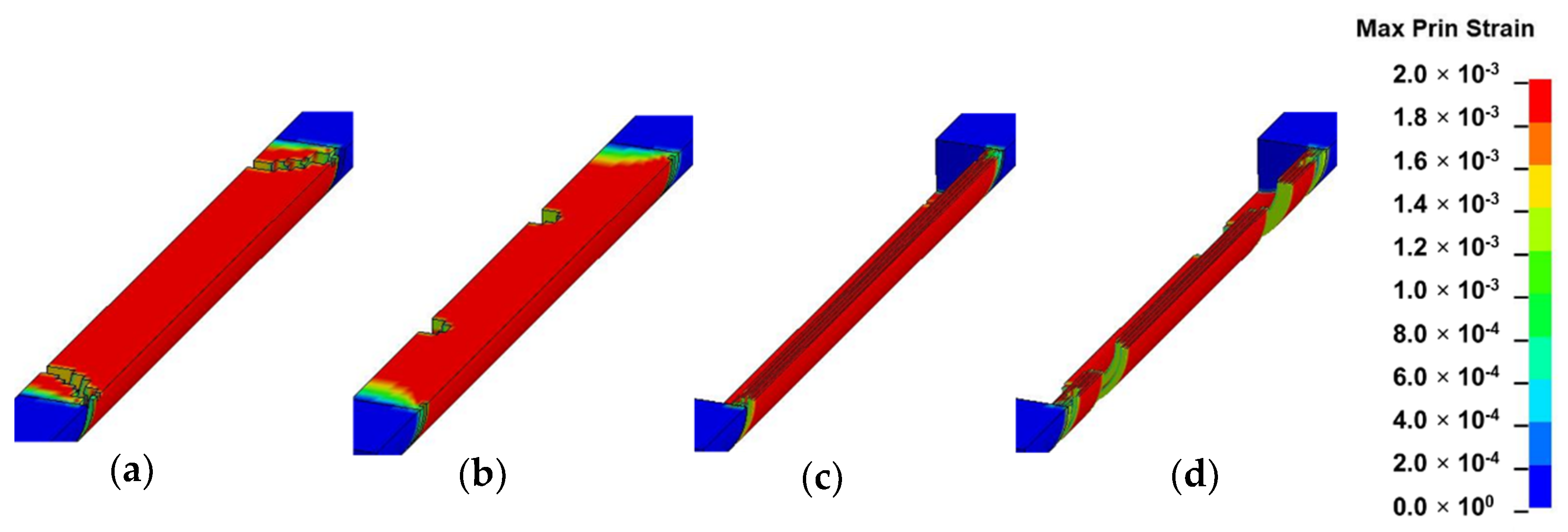
3.3.2. Shear
Shear failure, which was found to occur along distinct shear planes between fibers around the neutral axis (
Figure 15a–c), correspond to similar failure mechanisms observed in four-point bending of bamboo culms [
10]. The transverse strength in bamboo is further compromised by the inferior interlaminar strength prevailing between fiber bundles within the culm structure [
18,
29,
51]. Bamboo shows excellent ability to resist buckling due to the transverse load during bending and shear despite its radial and tangential stiffness being only about 1/20 of its longitudinal stiffness. The longitudinal fibers of superior strength are conglutinated together by a non-cellulose component. Both MOE results obtained by the experiment and bending and shear simulation results obtained by FEM showed that bamboo structures have a good capacity to resist transverse fractures, given their optimized strength, which stems from their specific organization structures. This uniquely optimized structure enables bamboo to adapt to bending loads caused by snow or wind while at the same time possessing a structure with a high strength-to-weight ratio [
17].
3.3.3. Compression
In compression, the crack which initiated from the outermost wall of the node-internode section was found to propagate at an angle of 45°, a mode of failure associated with shear band formation [
13]. According to Gauss et al., larger axial strain, which is observed near the middle of the culm at ultimate stress due to restriction by loading platens, will cause the section to bulge-out, leading to a split [
15].
3.3.4. Torsion
The observation made in the torsion mode corresponded to the results by Askarinejad et al., which showed that the maximum principal stress distribution of bamboo in torsion in finite element analysis was greatest on its outermost surface [
12]. Furthermore, a wider range in the variation of Von Mises stress was observed in bamboo in torsion mode as compared to the homogeneous isotropic model [
24].
3.4. Normalized Strain Distribution
In nature, the forces subjected in bending and shear modes are significantly higher in comparison to compression and torsion as its hollow structure, consisting of a large length-to-diameter ratio, undergoes substantial flexural deformation by transverse loading. However, in this study a constant displacement was applied to homogenize the boundary conditions prior to simulation in all modes of loading even though the actual case in nature is dissimilar. Even so, from the non-dimensional results of
Table 3, bamboo in the bending mode still underwent the largest deformation followed by torsion and shear. The unique geometrical structure of bamboo is thus able to withstand large deformation in the bending mode given their optimum natural design.
Based on the fracture mechanisms obtained by FEM simulations, and in comparison to the observed modes of failure in nature, the most common load combination to which bamboo is subjected is bending and shear loads. Its hollow and large length-to-diameter ratio structure is susceptible to large bending and shear deformations when subjected to lateral loading arising from wind.
3.5. Future Recommendation
Other important aspects of bamboo also not investigated in this study, but which significantly contribute to its anti-bending and anti-shearing capacities under transverse load, are its interlaminar strength, transverse hierarchical graded structure and systematically positioned nodes. Further numerical and experimental research involving the effects of these mentioned aspects is required and can be compared with the results of the simple case of the transversely isotropic model in this study to give better insight on fracture mechanisms in bamboo culm.
4. Conclusions
In this study, the fracture mechanisms of bamboo were investigated by FEM by considering the noticeable orthotropic characteristics which prevail in its axial direction. The characteristics of bamboo’s crack initiation were found to greatly differ from solid geometry and homogeneous material-type models. In contrast to other geometry-material models which simply displayed break point crack initiation notably in shear mode, distinctive splitting patterns were discerned in the hollow-inhomogeneous models in bending and shear modes. Furthermore, the location of the splitting varied in bending and shear modes which occurred in the inside-lowermost position of the culm and outside-center position, respectively. From the results of this study, it can be concluded that bamboo has developed an optimized transverse isotropic structure to predominantly resist transverse deformation due to bending and shear modes of loading. The fracture mechanisms observed in these modes corresponded to a large extent to failure observed in natural bamboo and as per the previously reported experimental investigations. This study can be furthered to shed light on the deformation mechanisms in artificially crafted complex composites with optimized structures based on bamboo-inspired bionic designs.


