Phase Change Materials Application in Battery Thermal Management System: A Review

 ,
,  , and
, and 
Abstract
: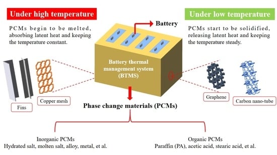
1. Introduction
2. Phase Change Material
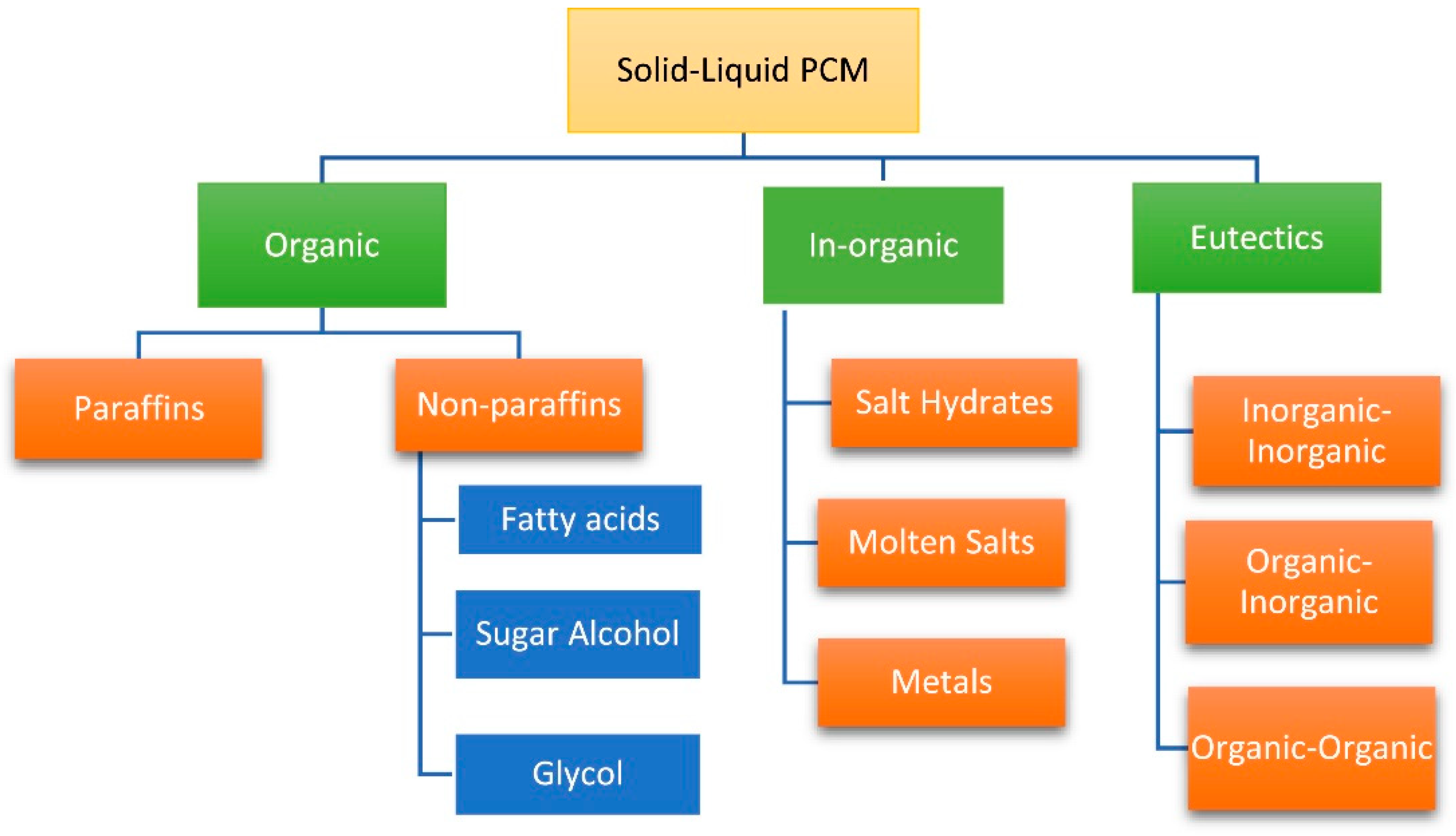
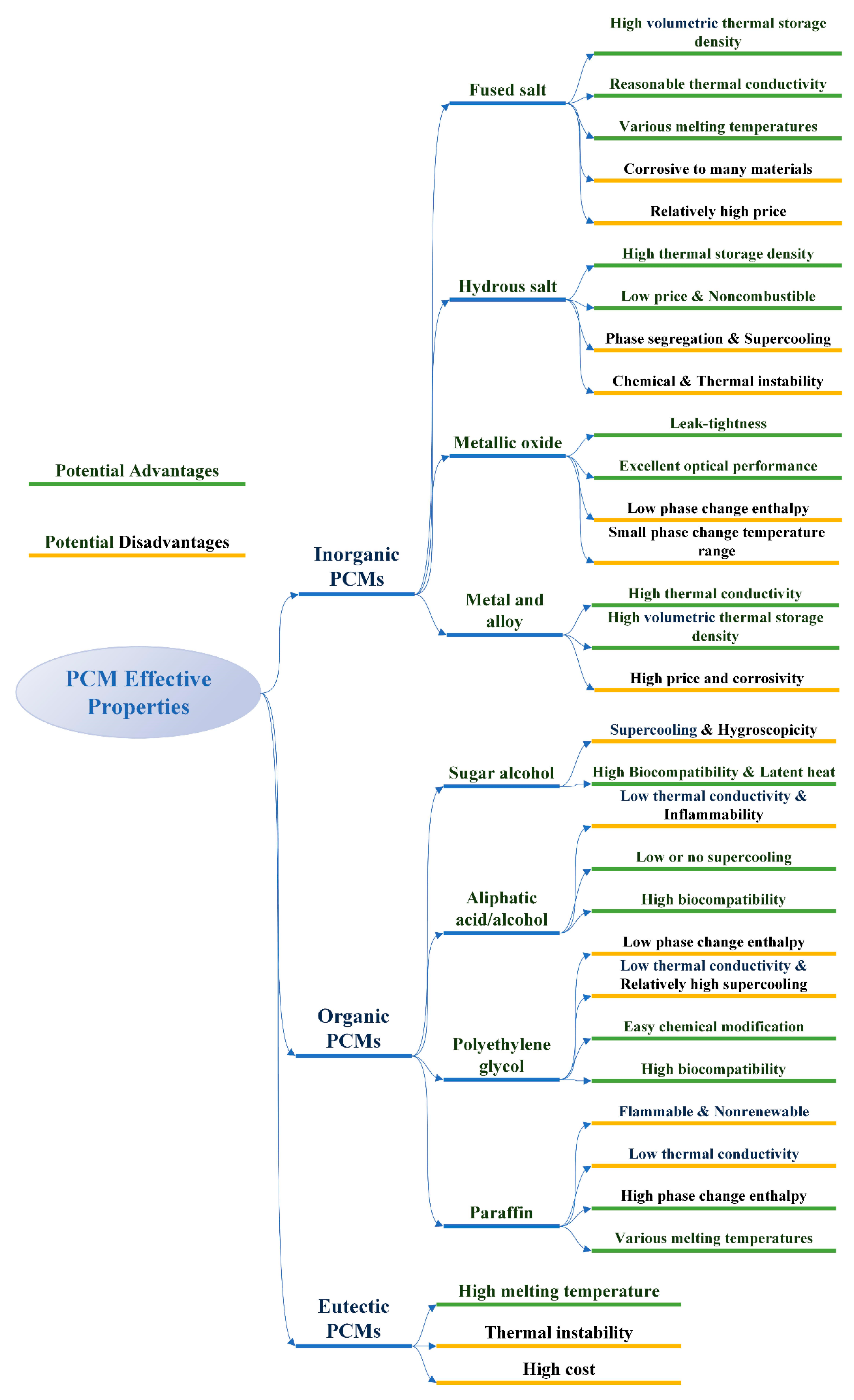
2.1. Classification of Phase Change Materials
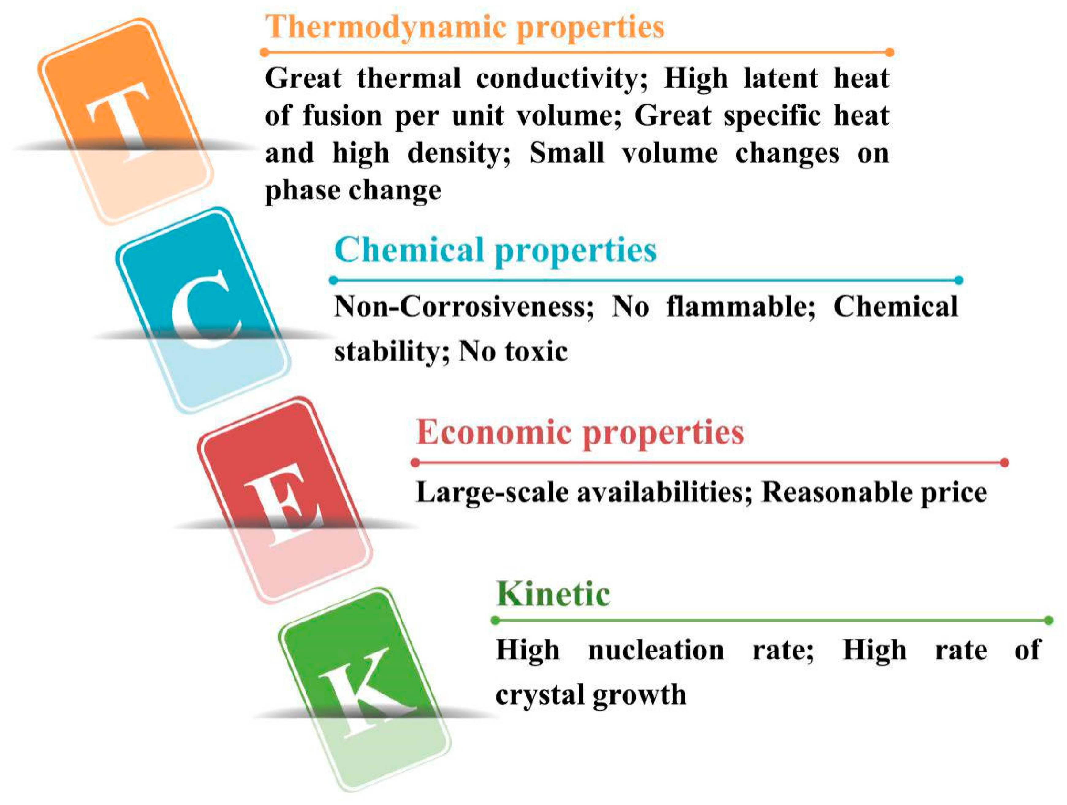
2.2. Selective Conditions of Phase Change Materials
- The phase transition temperature of PCM is within the scope of normal working temperature;
- Strong ability to absorb heat and get latent heat;
- Good thermal conductivity;
- Good chemical stability and chemical corrosion resistance;
- Low cost, easy to be obtained and not easy to leak;
- Low degree of supercooling.
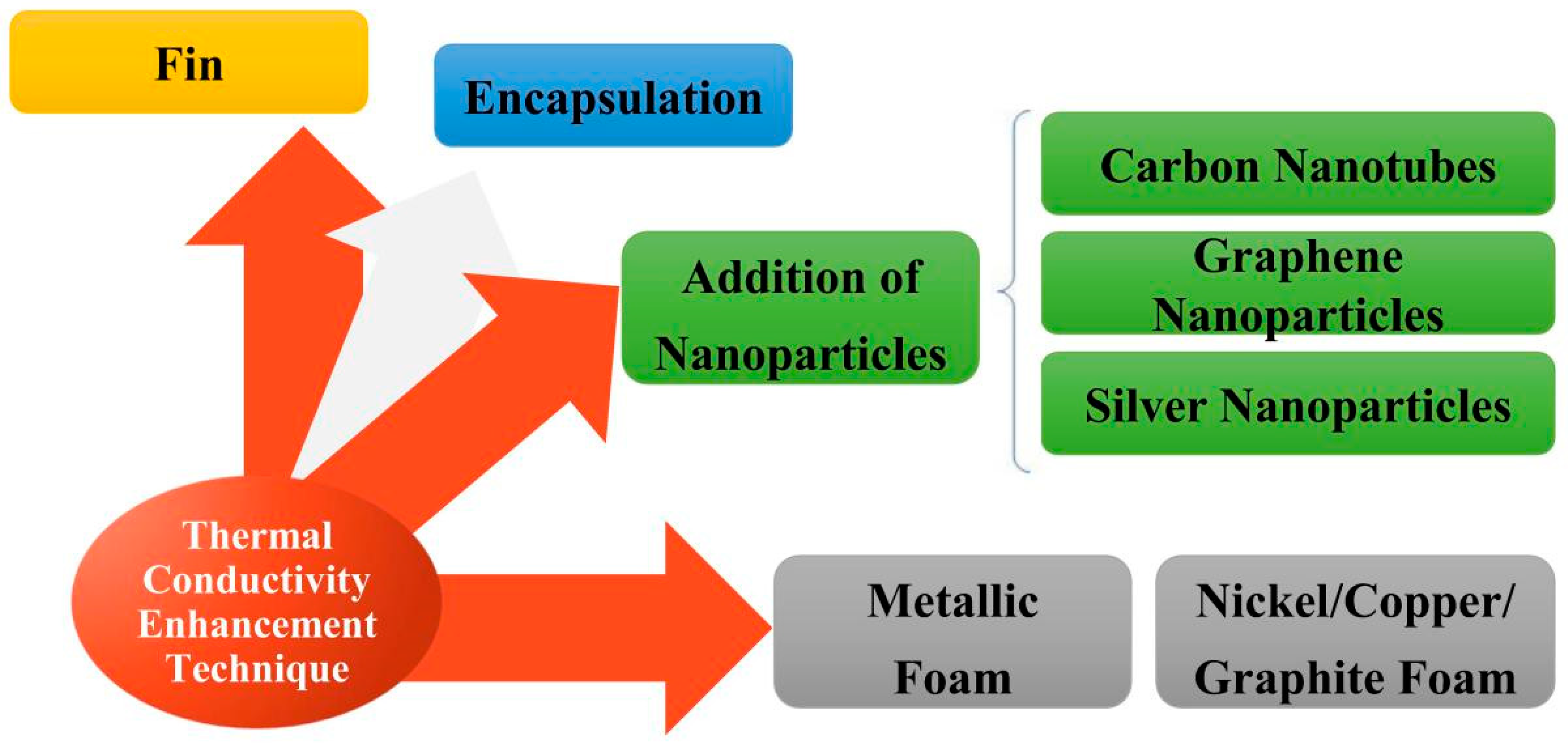
2.3. Enhancement of Phase Change Materials with Different Improving Methods
3. Adding High Heat-Conducting Fillers
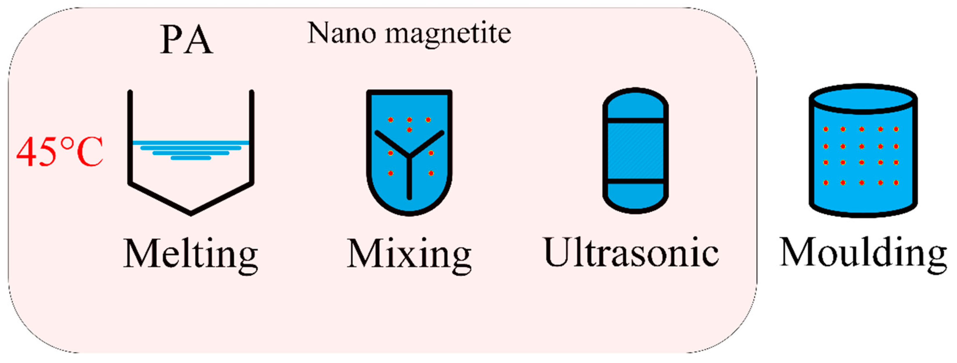
3.1. Adding Nanoparticles
3.1.1. The Effect of Adding Nanoparticles on the Thermal Conductivity by Changing Structure
3.1.2. The Effect of Adding Nanoparticles on Latent Heat
- Positive effect of nanoparticles: some studies have shown that the latent heat of composite PCM increased due to the presence of nanoparticles;
- Negative effect of nanoparticles: some studies have shown that the latent heat of composite PCM was reduced due to the presence of nanoparticles.
3.2. The Effect of Adding Metal Fillers
3.2.1. Metal Foams
3.2.2. Metal Particles
3.2.3. Semimetal Materials
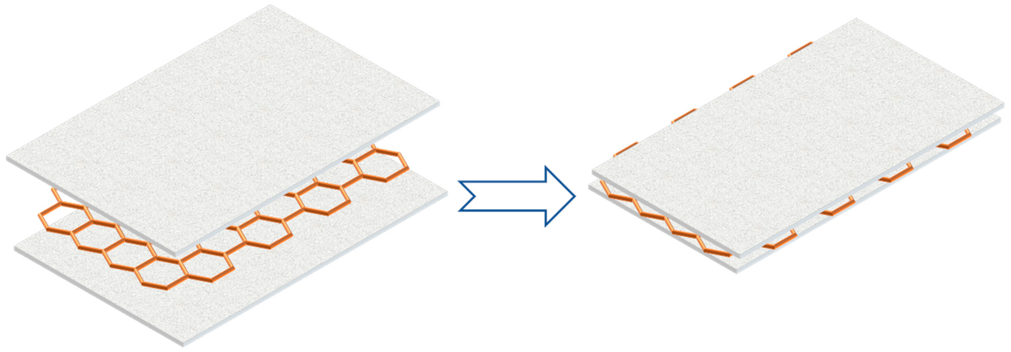
Carbon Fiber
Graphene Nano-Platelet
- Graphene and PA were tightly combined in structure without any microcracks or loose interfaces, which was also indicated by graphite flakes and PAs.
- The melting point of pure PA was higher than that of PCM composite.
- With increasing filler content as well as mass fraction, the enthalpy value of the composite PCM first increased and then decreased.
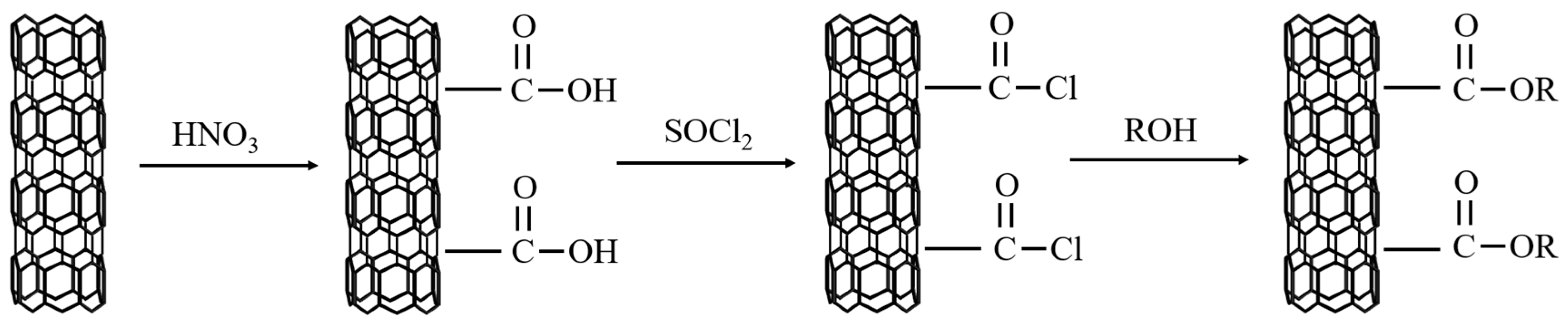
Carbon Nano-Tubes
3.3. Adding Non-Metallic Fillers
Expanded Graphite
- As the mass fraction and bulk density of EG increasing, the thermal conductivity of the composite PCM also increased, and the maximum value could be increased to 60 times higher;
- The thermal conductivity of the composite PCM was only related to the phase transition temperature with a range from 40 °C to 45 °C, and almost doubled after the modification, but there was nearly no change for thermal conductivity under temperatures beyond the range;
- With the increasing EG mass fraction, the specific heat capacity and specific latent heat of composite PCM decreased.
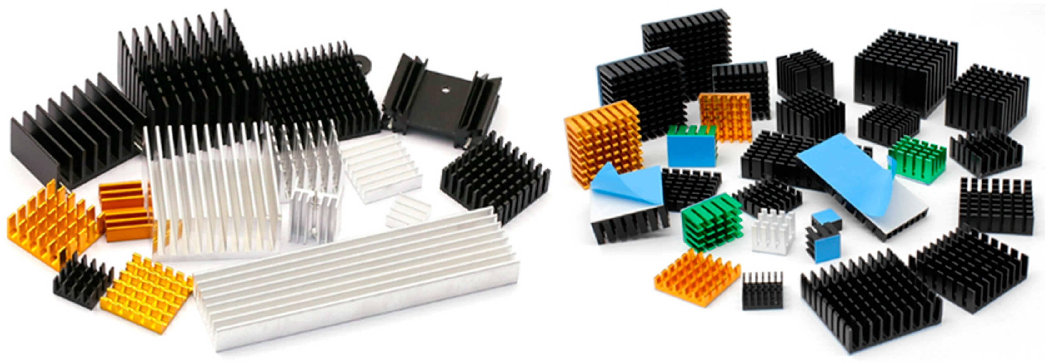
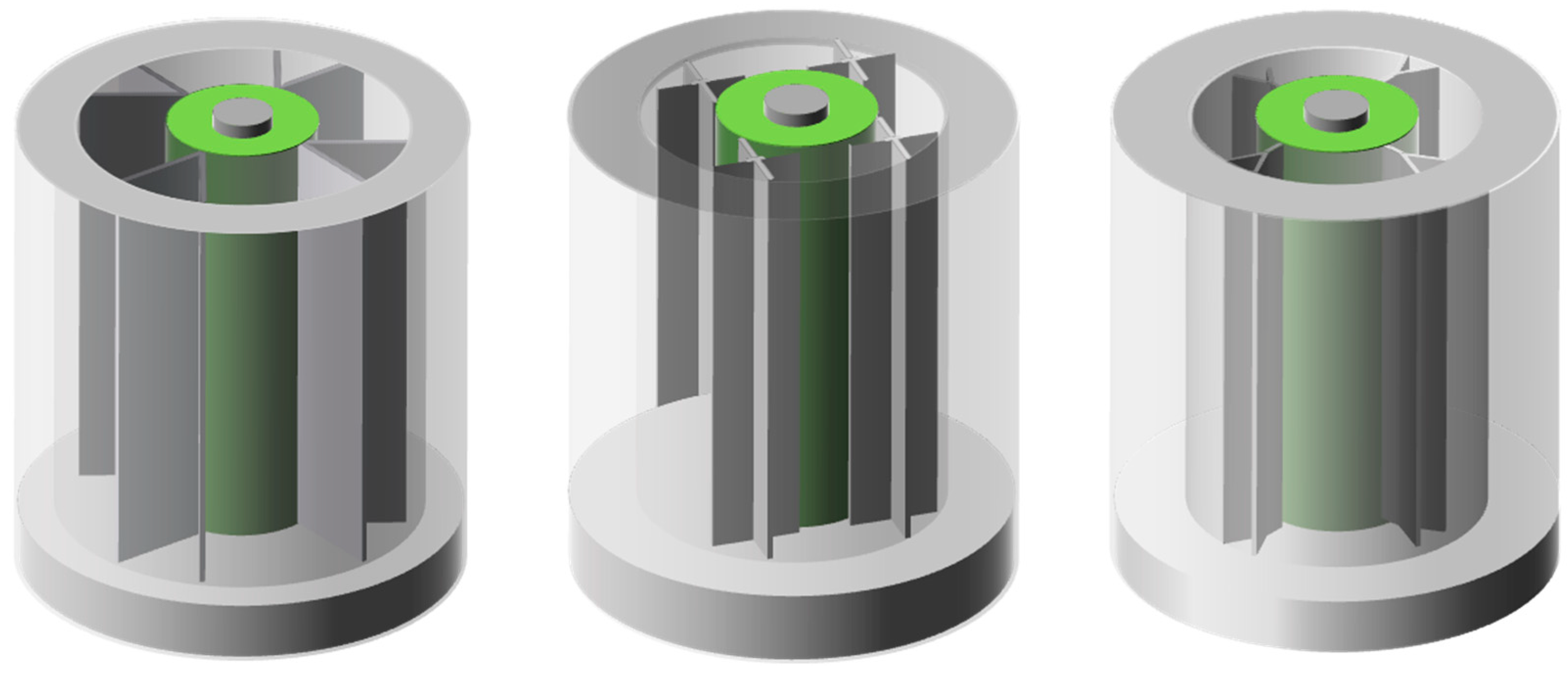
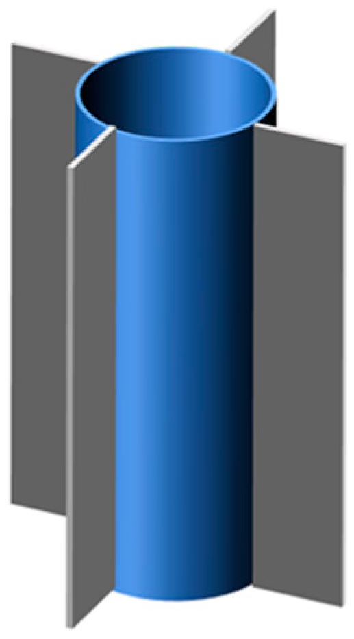
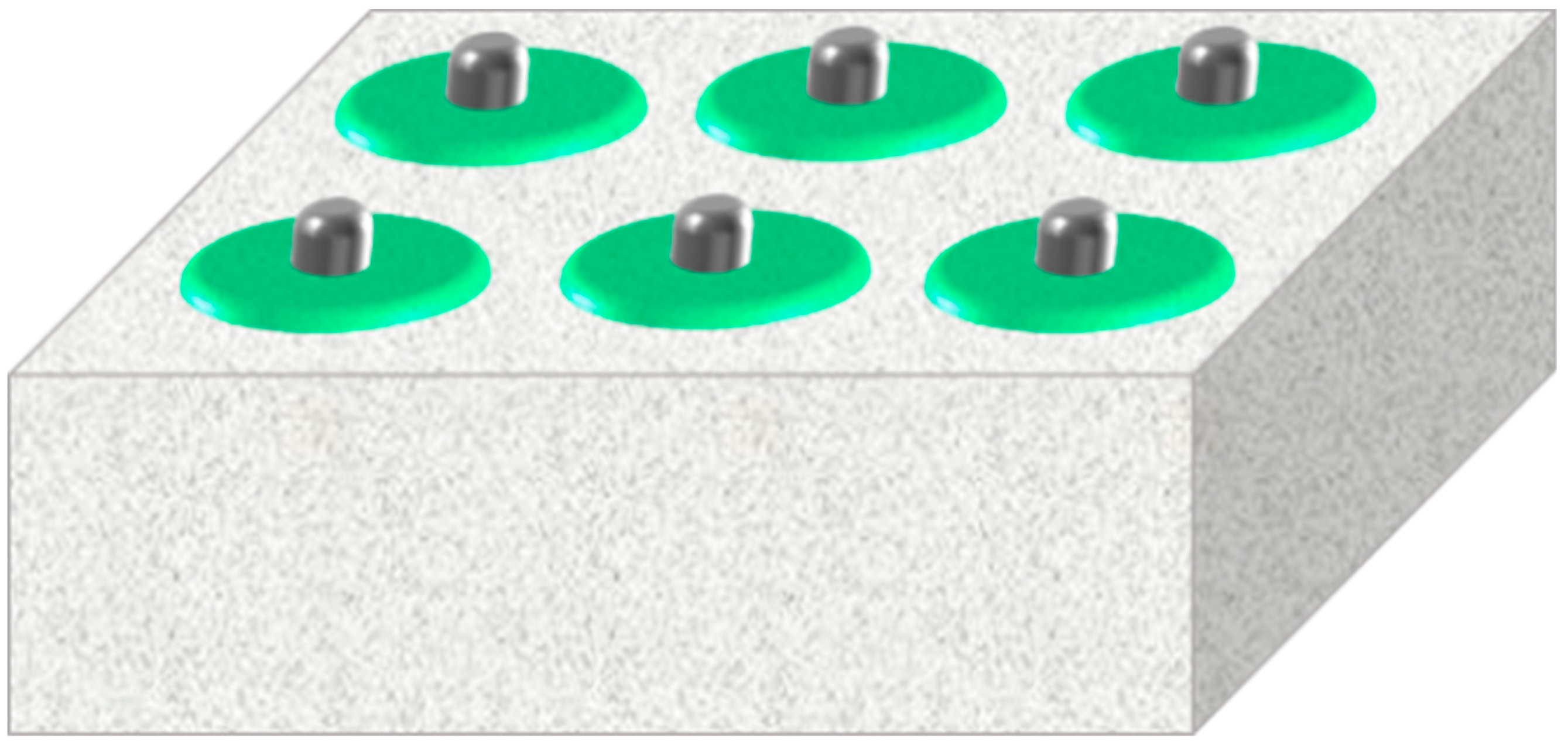
4. Fins
5. Packaging
5.1. Dispersed/Decentralized Packaging
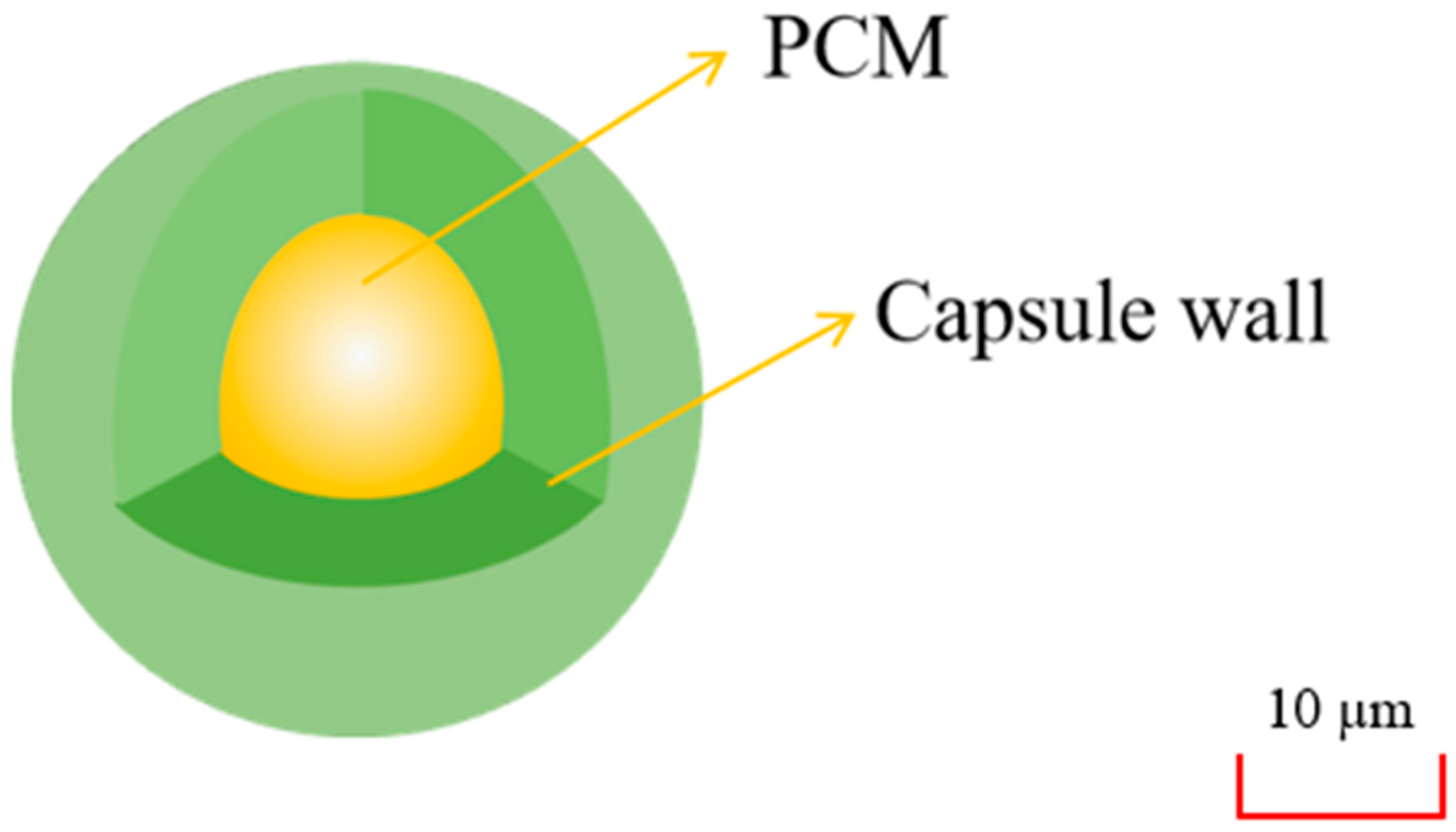
5.2. Microcapsule Packaging
- When the size of MPCM without silver plating decreased, the thermal conductivity also decreased;
- The thermal conductivity of silver-plated MPCM increased with the increase of size;
- The thermal conductivity of MPCM increased with the gain of the silver-plated coating coverage.
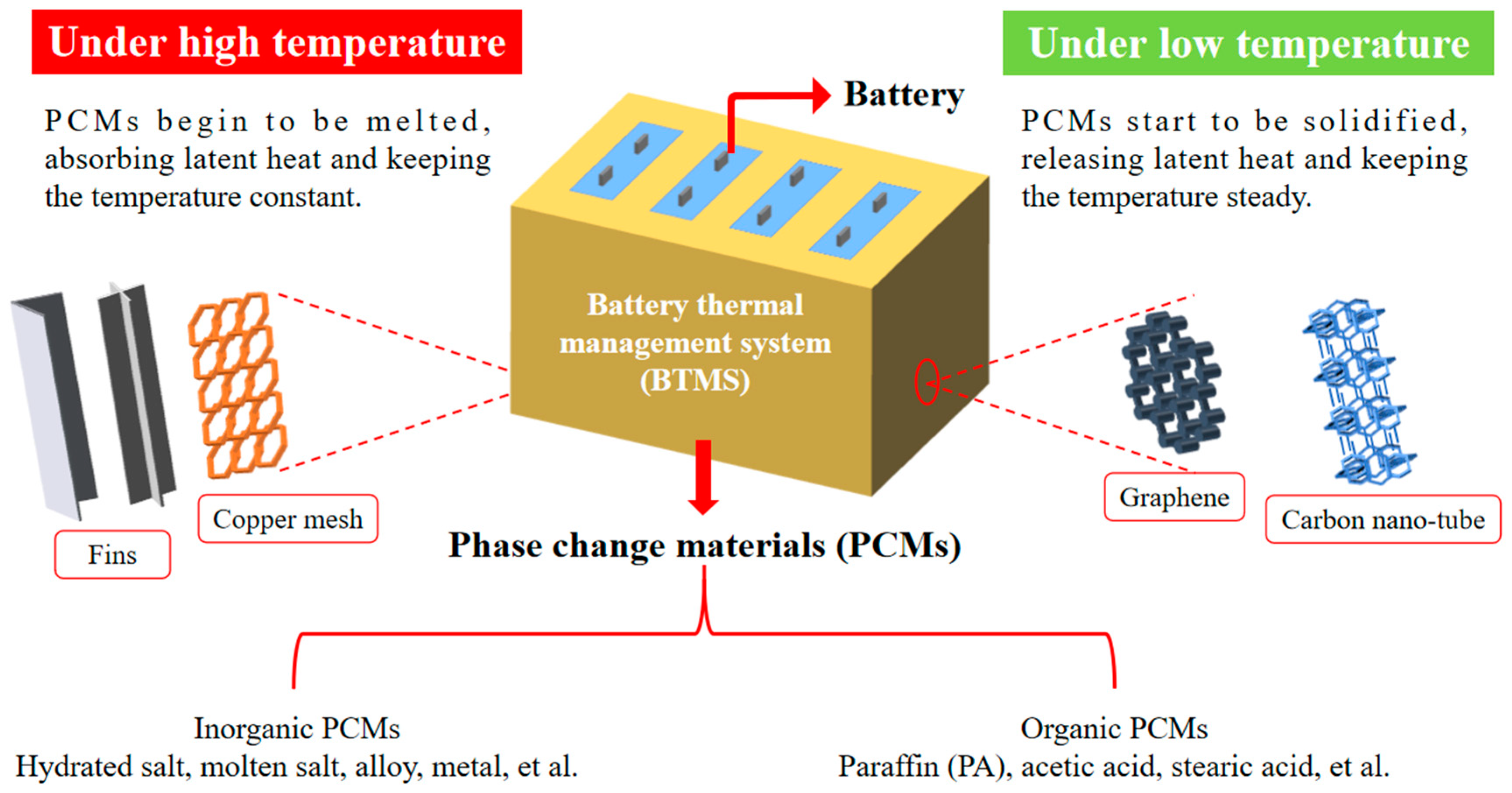
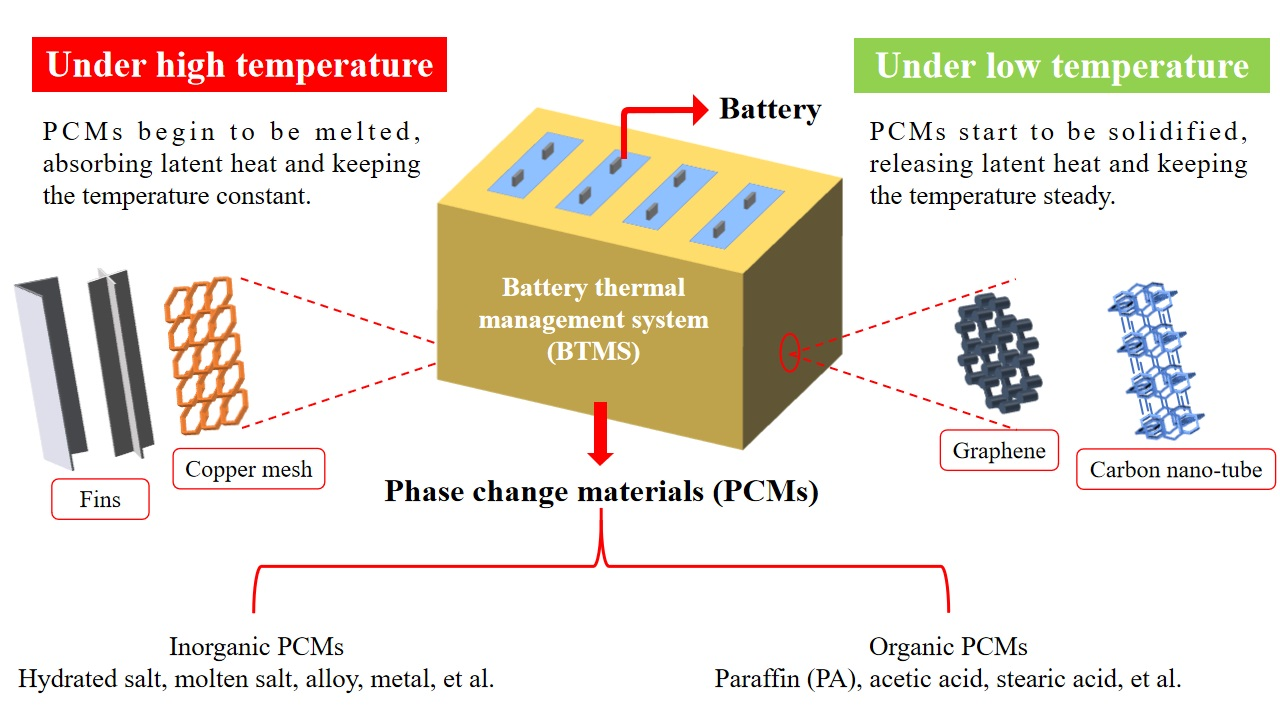
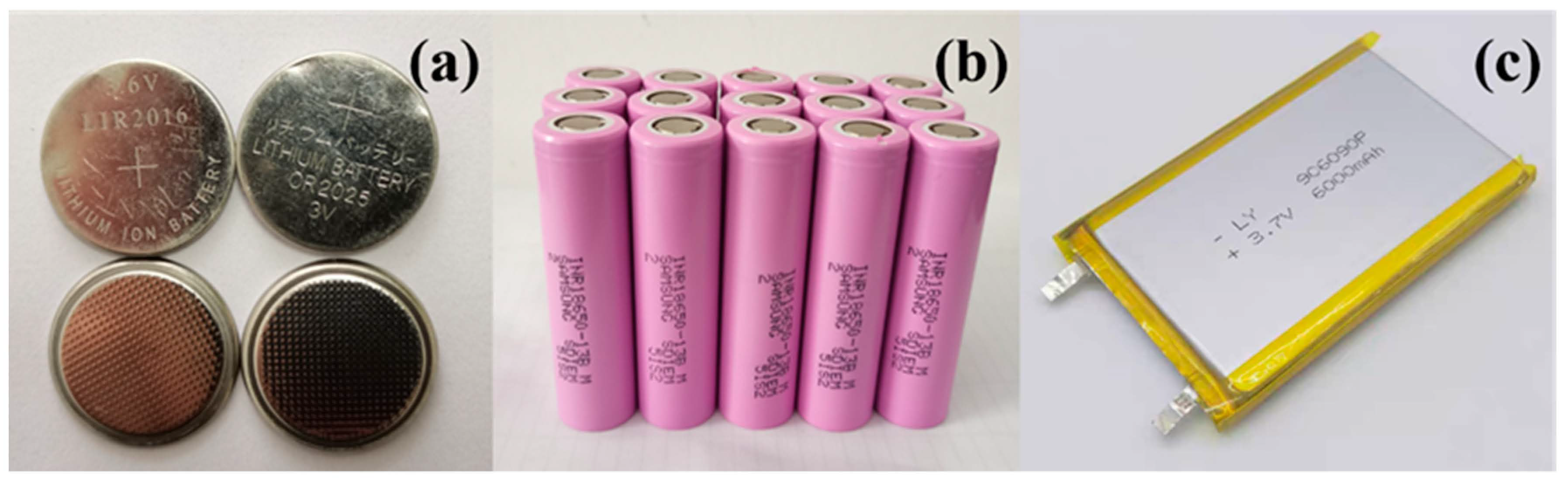
6. Phase Change Materials Application in Battery Thermal Management System
6.1. The Necessity of Phase Change Materials Application in Battery Thermal Management System
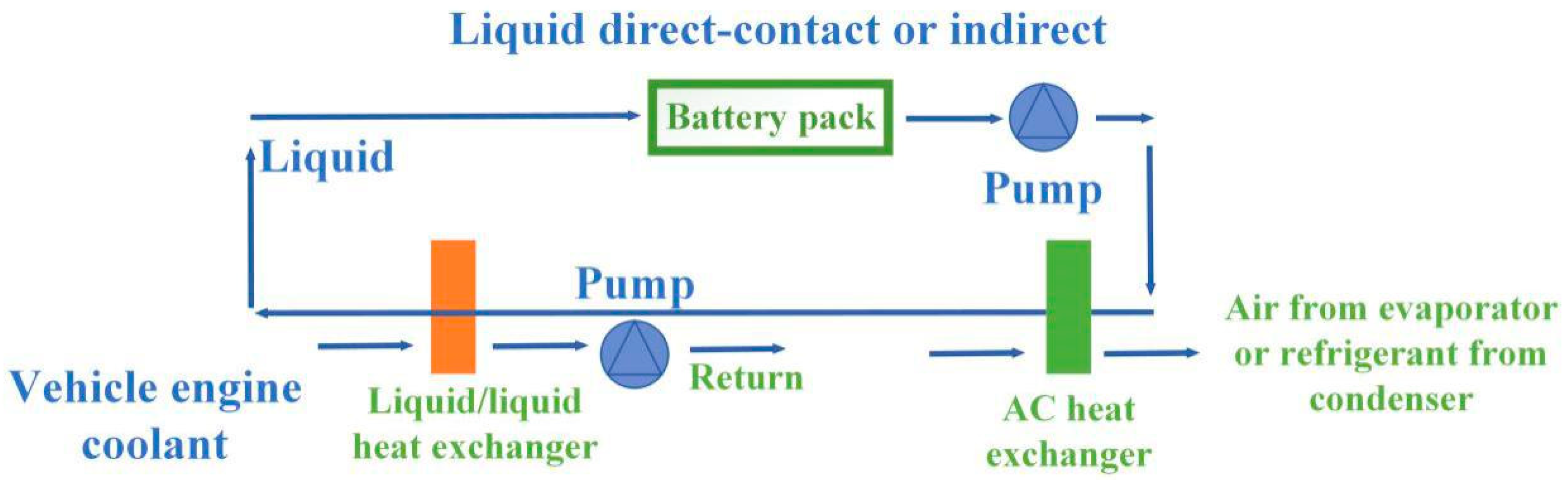
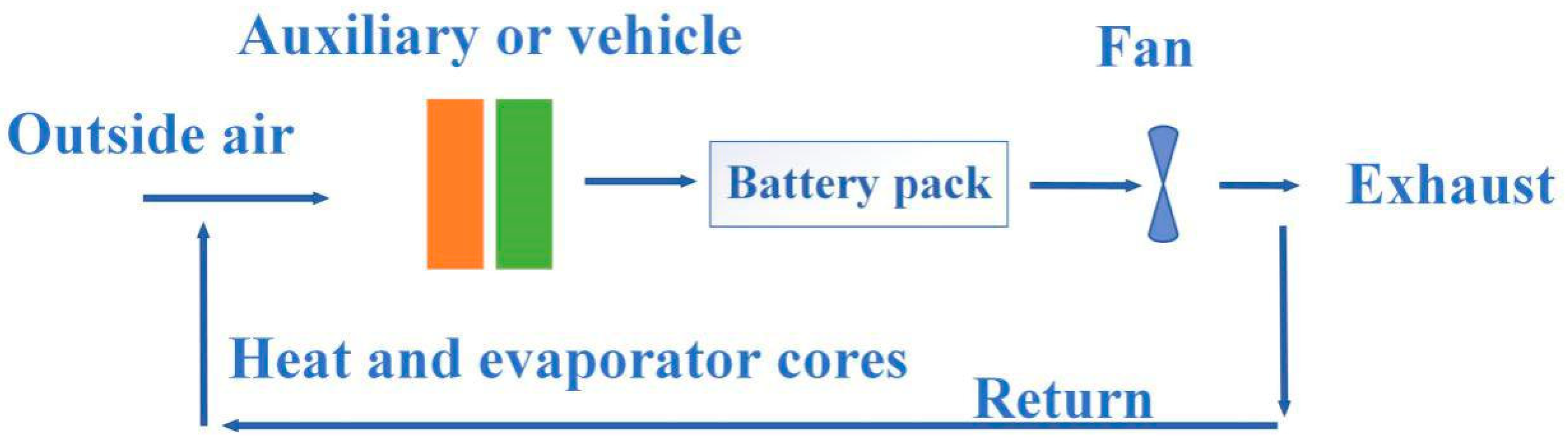
6.2. Traditional Battery Thermal Management System without Phase Change Materials
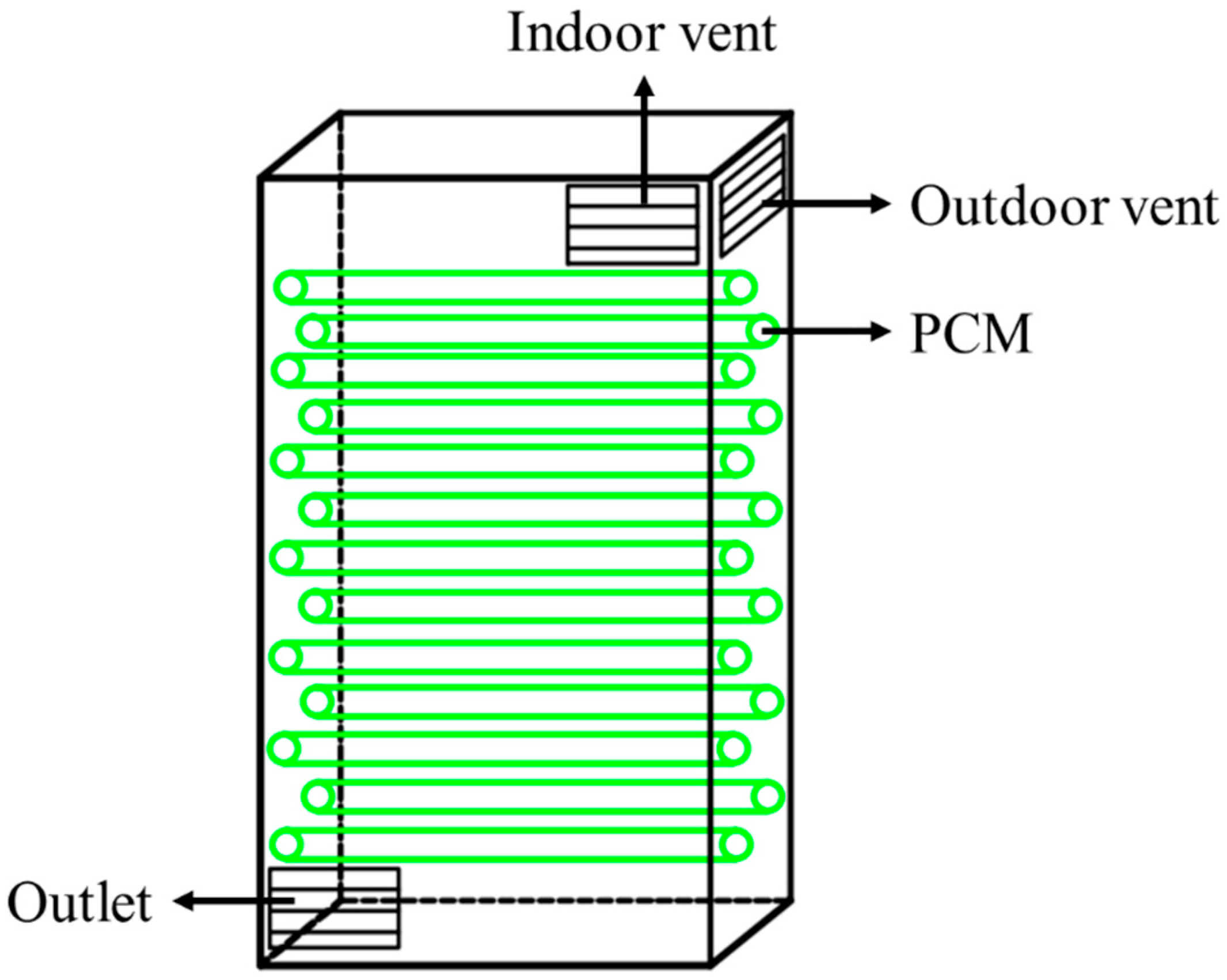
6.3. Phase Change Material-Based Battery Thermal Management System
7. Conclusions
- In terms of enhancing the PCM thermal conductivity, although the heat dissipation capacity of the system could be greatly improved by using metal fins, it would increase the system mass and the manufacturing cost to a certain extent. However, the method of adding fillers could only increase the thermal conductivity of PCM within a limited range, and it is necessary to collect relevant knowledge and comprehensively understand the mechanisms in the preparation stage. Thus, the threshold is high and it is necessary to choose the appropriate method reasonably in practical application.
- Passive thermal management system with PCM has the advantages of simple structure and low manufacturing cost. However, it is difficult to meet the needs when charging and discharging large battery packs, so it is mostly used for a small battery/cell pack. An active thermal management system based on PCM, which has complex structure and high manufacturing cost, is obviously more superior than the passive one in heat dissipation capacity, and the active one is very suitable for large-capacity battery packs. In practical application, a reasonable choice is needed to be considered.
- The structure of the BTMS with PCM needs to be further optimized to ensure the safety of the battery pack. In the meantime, the production cost and actual volume should be reduced, so that it could improve the safety of the battery efficiently.
- Making full use of the PCM characteristics could realize the design of a thermal management system that effectively recycles battery heat under supercooling conditions.
Author Contributions
Funding
Acknowledgments
Conflicts of Interest
Abbreviations
| BTMS | battery thermal management system |
| CB | carbon black |
| CF | carbon fiber |
| CM | copper mesh |
| CNT | carbon nanotubes |
| CNT-SA | carbon nanotubes with stearyl alcohol |
| CPCM | compounding phase change material |
| DOD | depths of discharge |
| DSC | differential scanning calorimetry |
| EG | expanded graphite |
| EP | expanded perlite |
| EV | electric vehicle |
| EVA | ethylene-vinyl acetate |
| GNP | graphene nano-platelet |
| HEV | hybrid electric vehicles |
| HP | heat pipe |
| HRR | heat release rate |
| LGPCM | liquid-gas phase change material |
| LIB | lithium-ion battery |
| MCH | magnesium chloride hexahydrate (MgCl2·6H2O) |
| MCMB | meso carbon microbeads |
| MPCM | microencapsulated phase change material |
| MWCNT | multi-walled carbon nanotube |
| NDG | nitrogen-doped graphene |
| NP | nickel particles |
| NREL | National Renewable Energy Laboratory |
| PA | paraffin |
| PCC | phase change composite |
| PCM | phase change material |
| PDA | polydopamine |
| PMMA | polymethyl methacrylate |
| SCF | short carbon fibers |
| SEI | solid electrolyte interface |
| SEM | scanning electron microscopy |
| SGPCM | solid-gas phase change material |
| SLPCM | solid-liquid phase change material |
| SSPCM | solid-solid phase change material |
| SWCNT | single-walled carbon nanotube |
| TCE | thermal conductivity enhancer |
| TCU | thermal control unit |
| TEM | transmission electron microscope |
| TES | thermal energy storage |
| TG | thermogravimetric |
| TR | thermal runaway |
| xGnP | exfoliated graphene nano-platelet |
References
- Kannan, N.; Vakeesan, D. Solar energy for future world: A review. Renew. Sustain. Energy Rev. 2016, 62, 1092–1105. [Google Scholar] [CrossRef]
- Lewis, N.S. Research opportunities to advance solar energy utilization. Science 2016, 351, aad1920. [Google Scholar] [CrossRef] [PubMed] [Green Version]
- Pérez-Collazo, C.; Greaves, D.; Iglesias, G. A review of combined wave and offshore wind energy. Renew. Sustain. Energy Rev. 2015, 42, 141–153. [Google Scholar] [CrossRef] [Green Version]
- Lewis, M.; Neill, S.; Robins, P.; Hashemi, M. Resource assessment for future generations of tidal-stream energy arrays. Energy 2015, 83, 403–415. [Google Scholar] [CrossRef] [Green Version]
- Weng, J.; Ouyang, D.; Yang, X.; Chen, M.; Zhang, G.; Wang, J. Alleviation of thermal runaway propagation in thermal management modules using aerogel felt coupled with flame-retarded phase change material. Energy Convers. Manag. 2019, 200, 112071. [Google Scholar] [CrossRef]
- Opitz, A.; Badami, P.; Shen, L.; Vignarooban, K.; Kannan, A. Can Li-Ion batteries be the panacea for automotive applications? Renew. Sustain. Energy Rev. 2017, 68, 685–692. [Google Scholar] [CrossRef] [Green Version]
- Maleki, H.; Howard, J.N. Effects of overdischarge on performance and thermal stability of a Li-ion cell. J. Power Sources 2006, 160, 1395–1402. [Google Scholar] [CrossRef]
- Weng, J.; Yang, X.; Ouyang, D.; Chen, M.; Zhang, G.; Wang, J. Comparative study on the transversal/lengthwise thermal failure propagation and heating position effect of lithium-ion batteries. Appl. Energy 2019, 255, 113761. [Google Scholar] [CrossRef]
- Belov, D.; Yang, M.-H. Failure mechanism of Li-ion battery at overcharge conditions. J. Solid State Electrochem. 2007, 12, 885–894. [Google Scholar] [CrossRef]
- Liang, J.; Gan, Y.; Li, Y. Investigation on the thermal performance of a battery thermal management system using heat pipe under different ambient temperatures. Energy Convers. Manag. 2018, 155, 1–9. [Google Scholar] [CrossRef]
- Al Hallaj, S.; Selman, J.R. ChemInform Abstract: A Novel Thermal Management System for Electric Vehicle Batteries Using Phase-Change Material. Chemin 2001, 32. [Google Scholar] [CrossRef]
- Al-Hallaj, S.; Selman, J. Thermal modeling of secondary lithium batteries for electric vehicle/hybrid electric vehicle applications. J. Power Sources 2002, 110, 341–348. [Google Scholar] [CrossRef]
- Goli, P.; Legedza, S.; Dhar, A.; Salgado, R.; Renteria, J.; Balandin, A.A. Graphene-enhanced hybrid phase change materials for thermal management of Li-ion batteries. J. Power Sources 2014, 248, 37–43. [Google Scholar] [CrossRef] [Green Version]
- Wu, W.; Yang, X.; Zhang, G.; Ke, X.; Wang, Z.; Situ, W.; Li, X.; Zhang, J. An experimental study of thermal management system using copper mesh-enhanced composite phase change materials for power battery pack. Energy 2016, 113, 909–916. [Google Scholar] [CrossRef]
- Zhang, X.; Liu, C.; Rao, Z. Experimental investigation on thermal management performance of electric vehicle power battery using composite phase change material. J. Clean. Prod. 2018, 201, 916–924. [Google Scholar] [CrossRef]
- Kim, J.; Oh, J.; Lee, H. Review on battery thermal management system for electric vehicles. Appl. Therm. Eng. 2019, 149, 192–212. [Google Scholar] [CrossRef]
- Javani, N.; Dincer, I.; Naterer, G.; Yilbas, B. Heat transfer and thermal management with PCMs in a Li-ion battery cell for electric vehicles. Int. J. Heat Mass Transf. 2014, 72, 690–703. [Google Scholar] [CrossRef]
- Ling, Z.; Wang, F.; Fang, X.; Gao, X.; Zhang, Z. A hybrid thermal management system for lithium ion batteries combining phase change materials with forced-air cooling. Appl. Energy 2015, 148, 403–409. [Google Scholar] [CrossRef] [Green Version]
- Zhao, J.; Lv, P.; Rao, Z. Experimental study on the thermal management performance of phase change material coupled with heat pipe for cylindrical power battery pack. Exp. Fluid Sci. 2017, 82, 182–188. [Google Scholar] [CrossRef]
- Farid, M.M.; Khudhair, A.M.; Razack, S.A.K.; Al-Hallaj, S. A review on phase change energy storage: Materials and applications. Energy Convers. Manag. 2004, 45, 1597–1615. [Google Scholar] [CrossRef]
- Faraj, K.; Khaled, M.; Faraj, J.; Hachem, F.; Castelain, C. A review on phase change materials for thermal energy storage in buildings: Heating and hybrid applications. J. Energy Storage 2020. [Google Scholar] [CrossRef]
- Khan, Z.; Khan, Z.A.; Ghafoor, A. A review of performance enhancement of PCM based latent heat storage system within the context of materials, thermal stability and compatibility. Energy Convers. Manag. 2016, 115, 132–158. [Google Scholar] [CrossRef]
- Huang, X.; Alva, G.; Jia, Y.; Fang, G. Morphological characterization and applications of phase change materials in thermal energy storage: A review. Renew. Sustain. Energy Rev. 2017, 72, 128–145. [Google Scholar] [CrossRef]
- Mohamed, S.A.; Al-Sulaiman, F.A.; Ibrahim, N.I.; Zahir, H.; Al-Ahmed, A.; Saidur, R.; Yılbaş, B.; Sahin, A. A review on current status and challenges of inorganic phase change materials for thermal energy storage systems. Renew. Sustain. Energy Rev. 2017, 70, 1072–1089. [Google Scholar] [CrossRef]
- Gunasekara, S.N.; Martin, V.; Chiu, J.N. Phase equilibrium in the design of phase change materials for thermal energy storage: State-of-the-art. Renew. Sustain. Energy Rev. 2017, 73, 558–581. [Google Scholar] [CrossRef]
- Pilar, R.; Svoboda, L.; Honcová, P.; Oravova, L. Study of magnesium chloride hexahydrate as heat storage material. Thermochim. Acta 2012, 546, 81–86. [Google Scholar] [CrossRef]
- Milián, Y.E.; Gutiérrez, A.; Grágeda, M.; Ushak, S. A review on encapsulation techniques for inorganic phase change materials and the influence on their thermophysical properties. Renew. Sustain. Energy Rev. 2017, 73, 983–999. [Google Scholar] [CrossRef]
- Yang, L.; Huang, J.-N.; Zhou, F. Thermophysical properties and applications of nano-enhanced PCMs: An update review. Energy Convers. Manag. 2020, 214, 112876. [Google Scholar] [CrossRef]
- Sharif, M.A.; Al-Abidi, A.; Mat, S.; Sopian, K.; Ruslan, M.; Sulaiman, M.; Rosli, M. Review of the application of phase change material for heating and domestic hot water systems. Renew. Sustain. Energy Rev. 2015, 42, 557–568. [Google Scholar] [CrossRef]
- Giro-Paloma, J.; Martínez, M.; Cabeza, L.F.; Fernández, A. Types, methods, techniques, and applications for microencapsulated phase change materials (MPCM): A review. Renew. Sustain. Energy Rev. 2016, 53, 1059–1075. [Google Scholar] [CrossRef] [Green Version]
- Jamekhorshid, A.; Sadrameli, S.; Farid, M. A review of microencapsulation methods of phase change materials (PCMs) as a thermal energy storage (TES) medium. Renew. Sustain. Energy Rev. 2014, 31, 531–542. [Google Scholar] [CrossRef]
- Ibrahim, N.I.; Al-Sulaiman, F.A.; Rahman, S.; Yilbas, B.S.; Sahin, A.Z. Heat transfer enhancement of phase change materials for thermal energy storage applications: A critical review. Renew. Sustain. Energy Rev. 2017, 74, 26–50. [Google Scholar] [CrossRef]
- Jebasingh, B.E.; Arasu, A.V. A comprehensive review on latent heat and thermal conductivity of nanoparticle dispersed phase change material for low-temperature applications. Energy Storage Mater. 2020, 24, 52–74. [Google Scholar] [CrossRef]
- Fan, L.; Khodadadi, J. Thermal conductivity enhancement of phase change materials for thermal energy storage: A review. Renew. Sustain. Energy Rev. 2011, 15, 24–46. [Google Scholar] [CrossRef]
- Khodadadi, J.; Fan, L.; Babaei, H. Thermal conductivity enhancement of nanostructure-based colloidal suspensions utilized as phase change materials for thermal energy storage: A review. Renew. Sustain. Energy Rev. 2013, 24, 418–444. [Google Scholar] [CrossRef]
- Kumar, N.; Hirschey, J.; LaClair, T.J.; Gluesenkamp, K.R.; Graham, S. Review of stability and thermal conductivity enhancements for salt hydrates. J. Energy Storage 2019, 24, 100794. [Google Scholar] [CrossRef]
- Lin, Y.; Jia, Y.; Alva, G.; Fang, G. Review on thermal conductivity enhancement, thermal properties and applications of phase change materials in thermal energy storage. Renew. Sustain. Energy Rev. 2018, 82, 2730–2742. [Google Scholar] [CrossRef]
- Liu, L.; Su, D.; Tang, Y.; Fang, G. Thermal conductivity enhancement of phase change materials for thermal energy storage: A review. Renew. Sustain. Energy Rev. 2016, 62, 305–317. [Google Scholar] [CrossRef]
- Mohamed, N.H.; Soliman, F.S.; El Maghraby, H.; Moustfa, Y. Thermal conductivity enhancement of treated petroleum waxes, as phase change material, by α nano alumina: Energy storage. Renew. Sustain. Energy Rev. 2017, 70, 1052–1058. [Google Scholar] [CrossRef]
- Qureshi, Z.A.; Ali, H.M.; Khushnood, S. Recent advances on thermal conductivity enhancement of phase change materials for energy storage system: A review. Int. J. Heat Mass Transf. 2018, 127, 838–856. [Google Scholar] [CrossRef]
- Wu, S.; Yan, T.; Kuai, Z.; Pan, W.-G. Thermal conductivity enhancement on phase change materials for thermal energy storage: A review. Energy Storage Mater. 2020, 25, 251–295. [Google Scholar] [CrossRef]
- Abdulateef, A.M.; Mat, S.; Abdulateef, J.; Sopian, K.; Al-Abidi, A.A. Geometric and design parameters of fins employed for enhancing thermal energy storage systems: A review. Renew. Sustain. Energy Rev. 2018, 82, 1620–1635. [Google Scholar] [CrossRef]
- Yang, L.; Du, K.; Zhang, Z. Heat transfer and flow optimization of a novel sinusoidal minitube filled with non-Newtonian SiC/EG-water nanofluids. Int. J. Mech. Sci. 2020, 168, 105310. [Google Scholar] [CrossRef]
- Afrand, M.; Kalbasi, R.; Karimipour, A.; Wongwises, S. Experimental Investigation on a Thermal Model for a Basin Solar Still with an External Reflector. Energies 2016, 10, 18. [Google Scholar] [CrossRef]
- Kalbasi, R.; Afrand, M.; Alsarraf, J.; Nguyen, T.K. Studies on optimum fins number in PCM-based heat sinks. Energy 2019, 171, 1088–1099. [Google Scholar] [CrossRef]
- Colla, L.; Fedele, L.; Mancin, S.; Danza, L.; Manca, O. Nano-PCMs for enhanced energy storage and passive cooling applications. Appl. Therm. Eng. 2017, 110, 584–589. [Google Scholar] [CrossRef]
- Ramakrishnan, S.; Wang, X.; Sanjayan, J.; Wilson, J. Heat Transfer Performance Enhancement of Paraffin/Expanded Perlite Phase Change Composites with Graphene Nano-platelets. Energy Procedia 2017, 105, 4866–4871. [Google Scholar] [CrossRef]
- Zhang, X.; Niu, J.; Wu, J.-Y. Development and characterization of novel and stable silicon nanoparticles-embedded PCM-in-water emulsions for thermal energy storage. Appl. Energy 2019, 238, 1407–1416. [Google Scholar] [CrossRef]
- Elbahjaoui, R.; El Qarnia, H. Thermal analysis of nanoparticle-enhanced phase change material solidification in a rectangular latent heat storage unit including natural convection. Energy Build. 2017, 153, 1–17. [Google Scholar] [CrossRef]
- Rufuss, D.D.W.; Suganthi, L.; Iniyan, S.; Davies, P. Effects of nanoparticle-enhanced phase change material (NPCM) on solar still productivity. J. Clean. Prod. 2018, 192, 9–29. [Google Scholar] [CrossRef] [Green Version]
- Chen, J.; Yang, D.; Jiang, J.; Ma, A.; Song, D. Research Progress of Phase Change Materials (PCMs) Embedded with Metal Foam (a Review). Procedia Mater. Sci. 2014, 4, 389–394. [Google Scholar] [CrossRef] [Green Version]
- Rangappa, R.; Rajoo, S. Numerical Analysis of PCM Based Thermal Management System for Li-Ion Battery Used in Hybrid and Electrical Vehicles. Proceedings of 3rd IRF International Conference, Hyderabad, India, 18 May 2014; ISBN 978-93-84209-18-6. Available online: https://www.researchgate.net/publication/327682070 (accessed on 15 October 2020).
- Zhang, P.; Meng, Z.; Zhu, H.; Wang, Y.; Peng, S. Melting heat transfer characteristics of a composite phase change material fabricated by paraffin and metal foam. Appl. Energy 2017, 185, 1971–1983. [Google Scholar] [CrossRef] [Green Version]
- Xiao, X.; Zhang, P.; Li, M. Preparation and thermal characterization of paraffin/metal foam composite phase change material. Appl. Energy 2013, 112, 1357–1366. [Google Scholar] [CrossRef]
- Xiao, X.; Zhang, P.; Li, M. Effective thermal conductivity of open-cell metal foams impregnated with pure paraffin for latent heat storage. Int. J. Sci. 2014, 81, 94–105. [Google Scholar] [CrossRef]
- Thapa, S.; Chukwu, S.; Khaliq, A.; Weiss, L. Fabrication and analysis of small-scale thermal energy storage with conductivity enhancement. Energy Convers. Manag. 2014, 79, 161–170. [Google Scholar] [CrossRef]
- Chen, Z.; Gao, D.; Shi, J. Experimental and numerical study on melting of phase change materials in metal foams at pore scale. Int. J. Heat Mass Transf. 2014, 72, 646–655. [Google Scholar] [CrossRef]
- Wang, Z.; Zhang, Z.; Jia, L.; Yang, L.-X. Paraffin and paraffin/aluminum foam composite phase change material heat storage experimental study based on thermal management of Li-ion battery. Appl. Eng. 2015, 78, 428–436. [Google Scholar] [CrossRef]
- Al Ghossein, R.M.; Hossain, M.S.; Khodadadi, J. Experimental determination of temperature-dependent thermal conductivity of solid eicosane-based silver nanostructure-enhanced phase change materials for thermal energy storage. Int. J. Heat Mass Transf. 2017, 107, 697–711. [Google Scholar] [CrossRef] [Green Version]
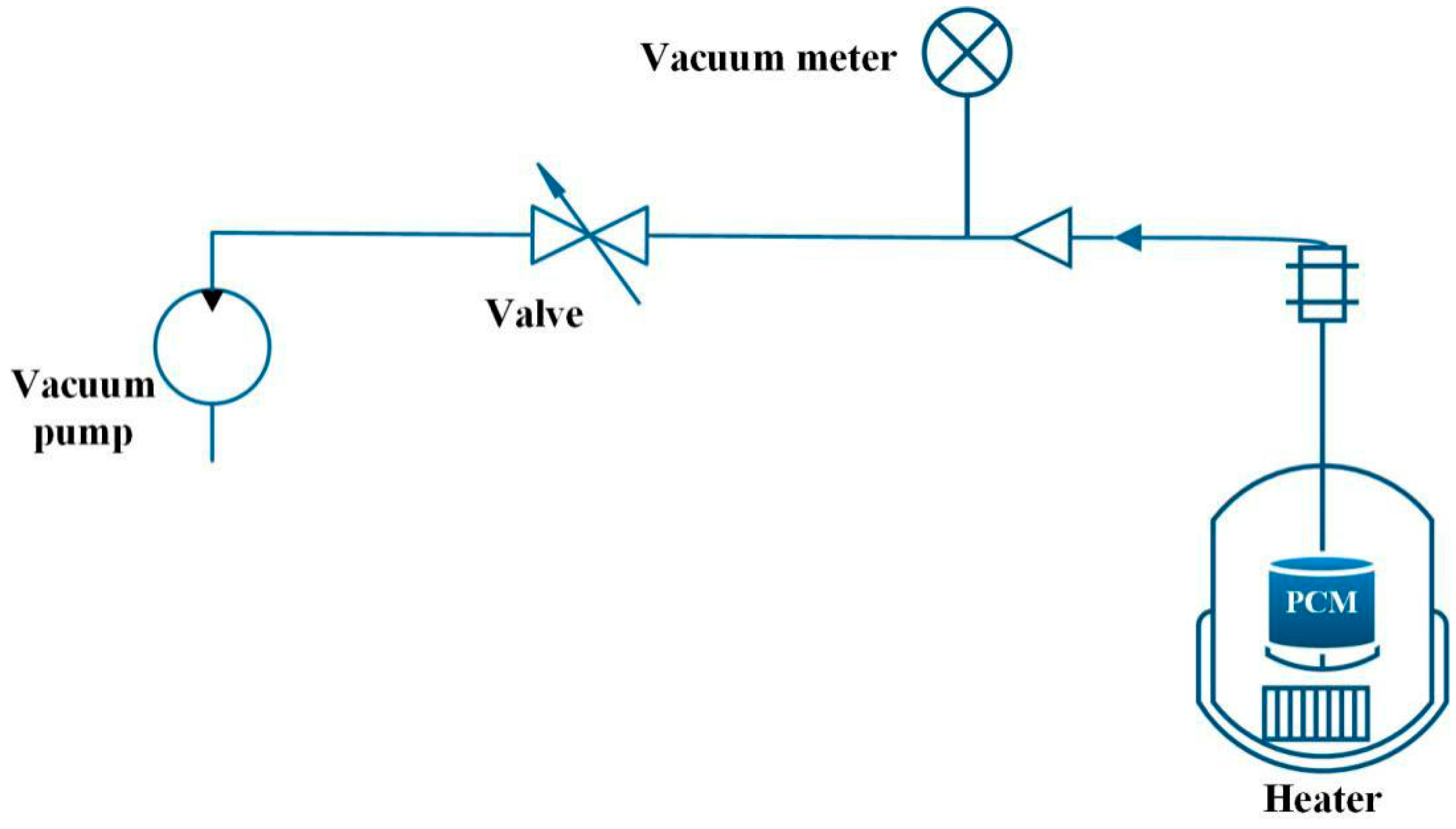
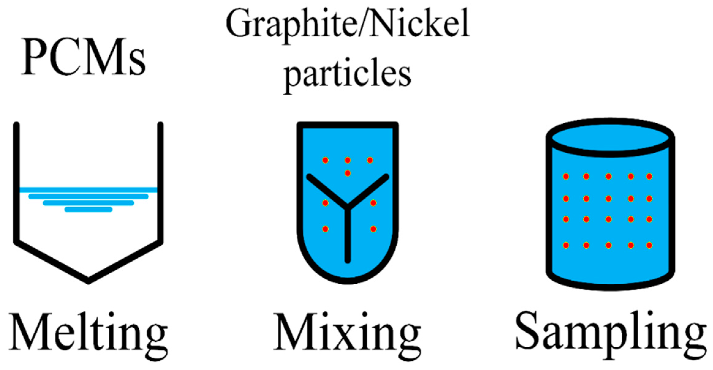
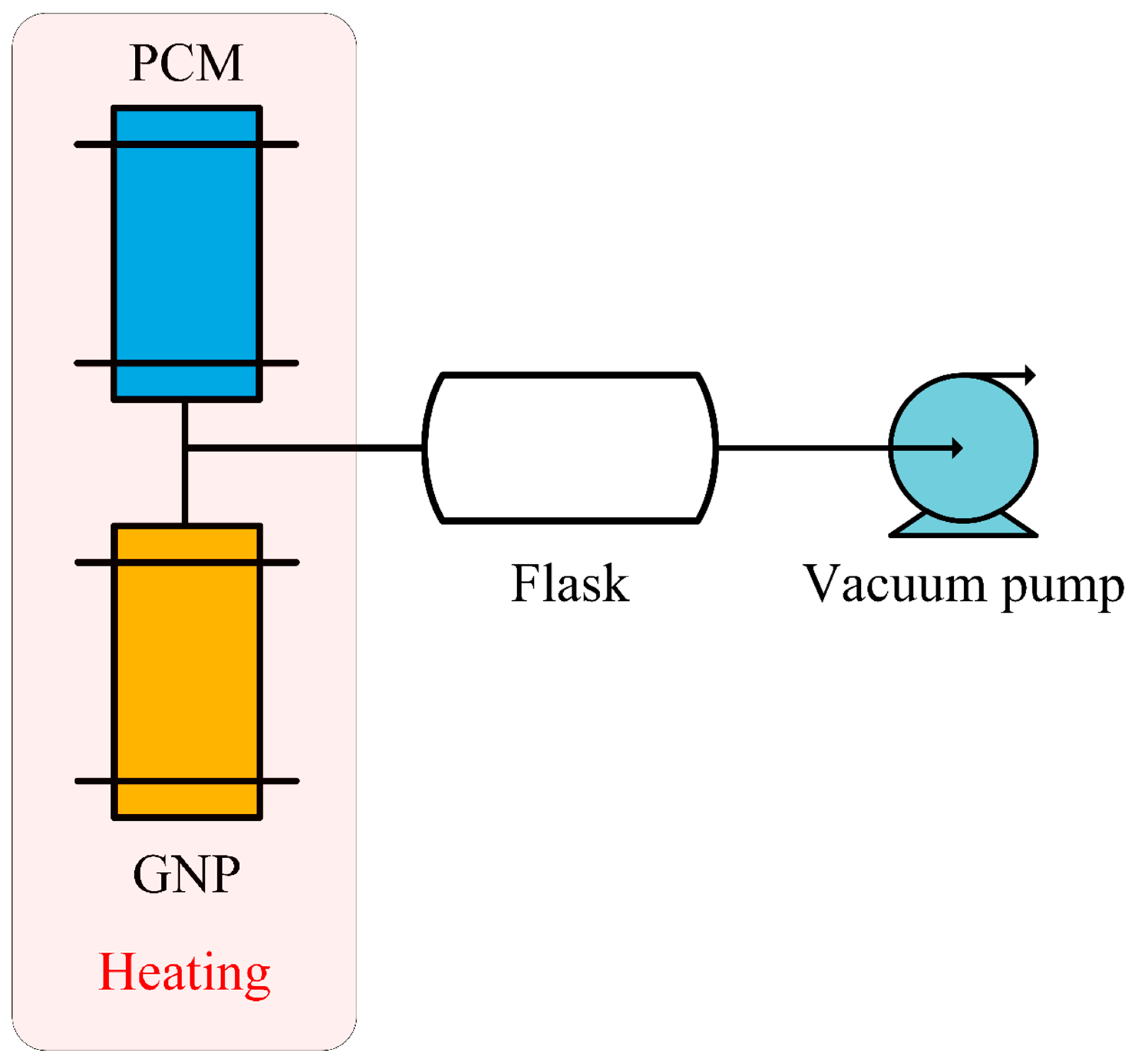
- Oya, T.; Nomura, T.; Tsubota, M.; Okinaka, N.; Akiyama, T. Thermal conductivity enhancement of erythritol as PCM by using graphite and nickel particles. Appl. Eng. 2013, 61, 825–828. [Google Scholar] [CrossRef]
- Cui, W.; Yuan, Y.; Sun, L.; Cao, X.; Yang, X. Experimental studies on the supercooling and melting/freezing characteristics of nano-copper/sodium acetate trihydrate composite phase change materials. Renew. Energy 2016, 99, 1029–1037. [Google Scholar] [CrossRef]
- Huang, X.; Alva, G.; Liu, L.; Fang, G. Microstructure and thermal properties of cetyl alcohol/high density polyethylene composite phase change materials with carbon fiber as shape-stabilized thermal storage materials. Appl. Energy 2017, 200, 19–27. [Google Scholar] [CrossRef]
- Babapoor, A.; Azizi, M.; Karimi, G. Thermal management of a Li-ion battery using carbon fiber-PCM composites. Appl. Eng. 2015, 82, 281–290. [Google Scholar] [CrossRef]
- Nomura, T.; Tabuchi, K.; Zhu, C.; Sheng, N.; Wang, S.; Akiyama, T. High thermal conductivity phase change composite with percolating carbon fiber network. Appl. Energy 2015, 154, 678–685. [Google Scholar] [CrossRef] [Green Version]
- Zhang, Q.; Luo, Z.; Guo, Q.; Wu, G. Preparation and thermal properties of short carbon fibers/erythritol phase change materials. Energy Convers. Manag. 2017, 136, 220–228. [Google Scholar] [CrossRef]
- Tian, B.; Yang, W.; Luo, L.; Wang, J.; Zhang, K.; Fan, J.; Wu, J.; Xing, T. Synergistic enhancement of thermal conductivity for expanded graphite and carbon fiber in paraffin/EVA form-stable phase change materials. Sol. Energy 2016, 127, 48–55. [Google Scholar] [CrossRef]
- Fu, Y.-X.; He, Z.-X.; Mo, D.-C.; Lu, S.-S. Thermal conductivity enhancement of epoxy adhesive using graphene sheets as additives. Int. J. Sci. 2014, 86, 276–283. [Google Scholar] [CrossRef]
- Harish, S.; Orejon, D.; Takata, Y.; Kohno, M. Thermal conductivity enhancement of lauric acid phase change nanocomposite with graphene nanoplatelets. Appl. Therm. Eng. 2015, 80, 205–211. [Google Scholar] [CrossRef]
- Mehrali, M.; Latibari, S.T.; Mehrali, M.; Mahlia, T.M.I.; Metselaar, H.S.C.; Naghavi, M.S.; Sadeghinezhad, E.; Akhiani, A.R. Preparation and characterization of palmitic acid/graphene nanoplatelets composite with remarkable thermal conductivity as a novel shape-stabilized phase change material. Appl. Therm. Eng. 2013, 61, 633–640. [Google Scholar] [CrossRef]
- Amin, M.; Putra, N.; Kosasih, E.A.; Prawiro, E.; Luanto, R.A.; Mahlia, T. Thermal properties of beeswax/graphene phase change material as energy storage for building applications. Appl. Therm. Eng. 2017, 112, 273–280. [Google Scholar] [CrossRef]
- Liu, X.; Rao, Z. Experimental study on the thermal performance of graphene and exfoliated graphite sheet for thermal energy storage phase change material. Thermochim. Acta 2017, 647, 15–21. [Google Scholar] [CrossRef]
- Li, J.; Lu, W.; Zeng, Y.; Luo, Z. Simultaneous enhancement of latent heat and thermal conductivity of docosane-based phase change material in the presence of spongy graphene. Sol. Energy Mater. Sol. Cells 2014, 128, 48–51. [Google Scholar] [CrossRef]
- Mehrali, M.; Latibari, S.T.; Mehrali, M.; Mahlia, T.M.I.; Sadeghinezhad, E.; Metselaar, H.S.C. Preparation of nitrogen-doped graphene/palmitic acid shape stabilized composite phase change material with remarkable thermal properties for thermal energy storage. Appl. Energy 2014, 135, 339–349. [Google Scholar] [CrossRef]
- Warzoha, R.J.; Fleischer, A.S. Effect of carbon nanotube interfacial geometry on thermal transport in solid–liquid phase change materials. Appl. Energy 2015, 154, 271–276. [Google Scholar] [CrossRef] [Green Version]
- Wang, J.F.; Xie, H.Q.; Xin, Z.; Li, Y. Experimental study on palmitic acid composites containing carbon nanotubes by acid treatment. J. Eng. Thermophys. 2010, 31, 1389–1391. [Google Scholar] [CrossRef]
- Xing, M.; Yu, J.; Wang, R. Experimental study on the thermal conductivity enhancement of water based nanofluids using different types of carbon nanotubes. Int. J. Heat Mass Transf. 2015, 88, 609–616. [Google Scholar] [CrossRef]
- Tao, Y.; Lin, C.; He, Y. Preparation and thermal properties characterization of carbonate salt/carbon nanomaterial composite phase change material. Energy Convers. Manag. 2015, 97, 103–110. [Google Scholar] [CrossRef]
- Ye, F.; Ge, Z.; Ding, Y.; Yang, J. Multi-walled carbon nanotubes added to Na2CO3/MgO composites for thermal energy storage. Particuology 2014, 15, 56–60. [Google Scholar] [CrossRef]
- Xu, B.; Li, Z. Paraffin/diatomite/multi-wall carbon nanotubes composite phase change material tailor-made for thermal energy storage cement-based composites. Energy 2014, 72, 371–380. [Google Scholar] [CrossRef]
- Li, M.; Chen, M.; Wu, Z.; Liu, J. Carbon nanotube grafted with polyalcohol and its influence on the thermal conductivity of phase change material. Energy Convers. Manag. 2014, 83, 325–329. [Google Scholar] [CrossRef]
- Li, M.; Chen, M.; Wu, Z. Enhancement in thermal property and mechanical property of phase change microcapsule with modified carbon nanotube. Appl. Energy 2014, 127, 166–171. [Google Scholar] [CrossRef]
- Şahan, N.; Fois, M.; Paksoy, H. Improving thermal conductivity phase change materials—A study of paraffin nanomagnetite composites. Sol. Energy Mater. Sol. Cells 2015, 137, 61–67. [Google Scholar] [CrossRef]
- Babapoor, A.; Karimi, G. Thermal properties measurement and heat storage analysis of paraffinnanoparticles composites phase change material: Comparison and optimization. Appl. Therm. Eng. 2015, 90, 945–951. [Google Scholar] [CrossRef]
- Meng, Z.; Zhang, P. Experimental and numerical investigation of a tube-in-tank latent thermal energy storage unit using composite PCM. Appl. Energy 2017, 190, 524–539. [Google Scholar] [CrossRef]
- Ling, Z.; Chen, J.; Xu, T.; Fang, X.; Gao, X.; Zhang, Z. Thermal conductivity of an organic phase change material/expanded graphite composite across the phase change temperature range and a novel thermal conductivity model. Energy Convers. Manag. 2015, 102, 202–208. [Google Scholar] [CrossRef] [Green Version]
- Ali, H.M.; Arshad, A. Experimental investigation of n-eicosane based circular pin-fin heat sinks for passive cooling of electronic devices. Int. J. Heat Mass Transf. 2017, 112, 649–661. [Google Scholar] [CrossRef]
- Yazici, M.Y.; Avci, M.; Aydin, O. Combined effects of inclination angle and fin number on thermal performance of a PCM-based heat sink. Appl. Therm. Eng. 2019, 159, 113956. [Google Scholar] [CrossRef]
- Arshad, A.; Ali, H.M. Thermal management of electronics: An experimental analysis of triangular, rectangular and circular pin-fin heat sinks for various PCMs. Int. J. Heat Mass Transf. 2018, 123, 272–284. [Google Scholar] [CrossRef]
- Ji, C.; Qin, Z.; Low, Z.; Dubey, S.; Choo, F.H.; Duan, F. Non-uniform heat transfer suppression to enhance PCM melting by angled fins. Appl. Therm. Eng. 2018, 129, 269–279. [Google Scholar] [CrossRef]
- Mahdi, J.M.; Lohrasbi, S.; Ganji, D.D.; Nsofor, E.C. Simultaneous energy storage and recovery in the triplex-tube heat exchanger with PCM, copper fins and Al2O3 nanoparticles. Energy Convers. Manag. 2019, 180, 949–961. [Google Scholar] [CrossRef]
- Yagci, O.K.; Avci, M.; Aydin, O. Melting and solidification of PCM in a tube-in-shell unit: Effect of fin edge lengths’ ratio. J. Energy Storage 2019, 24, 100802. [Google Scholar] [CrossRef]
- Tian, L.-L.; Liu, X.; Chen, S.; Shen, Z.-G. Effect of fin material on PCM melting in a rectangular enclosure. Appl. Therm. Eng. 2020, 167, 114764. [Google Scholar] [CrossRef]
- Ji, C.; Qin, Z.; Dubey, S.; Choo, F.H.; Duan, F. Simulation on PCM melting enhancement with double-fin length arrangements in a rectangular enclosure induced by natural convection. Int. J. Heat Mass Transf. 2018, 127, 255–265. [Google Scholar] [CrossRef]
- Tauseef-ur-Rehman; Ali, H.M. Experimental investigation on paraffin wax integrated with copper foam based heat sinks for electronic components thermal cooling. Int Commun Heat Mass Tran. 2018, 98, 155–162. [Google Scholar] [CrossRef]
- Acır, A.; Canli, M.E. Investigation of fin application effects on melting time in a latent thermal energy storage system with phase change material (PCM). Appl. Therm. Eng. 2018, 144, 1071–1080. [Google Scholar] [CrossRef]
- Kamkari, B.; Shokouhmand, H. Experimental investigation of phase change material melting in rectangular enclosures with horizontal partial fins. Int. J. Heat Mass Transf. 2014, 78, 839–851. [Google Scholar] [CrossRef]
- Biwolé, P.H.; Groulx, D.; Souayfane, F.; Chiu, T. Influence of fin size and distribution on solid-liquid phase change in a rectangular enclosure. Int. J. Therm. Sci. 2018, 124, 433–446. [Google Scholar] [CrossRef]
- Xie, J.; Lee, H.M.; Xiang, J. Numerical study of thermally optimized metal structures in a Phase Change Material (PCM) enclosure. Appl. Therm. Eng. 2019, 148, 825–837. [Google Scholar] [CrossRef]
- Weng, J.; Ouyang, D.; Yang, X.; Chen, M.; Zhang, G.; Wang, J. Optimization of the internal fin in a phase-change-material module for battery thermal management. Appl. Therm. Eng. 2020, 167, 114698. [Google Scholar] [CrossRef]
- Weng, J.; He, Y.; Ouyang, D.; Yang, X.; Zhang, G.; Wang, J. Thermal performance of PCM and branch-structured fins for cylindrical power battery in a high-temperature environment. Energy Convers. Manag. 2019, 200, 112106. [Google Scholar] [CrossRef]
- Zhao, C.; Opolot, M.; Liu, M.; Bruno, F.; Mancin, S.; Hooman, K. Numerical study of melting performance enhancement for PCM in an annular enclosure with internal-external fins and metal foams. Int. J. Heat Mass Transf. 2020, 150, 119348. [Google Scholar] [CrossRef]
- Sun, Z.; Fan, R.; Yan, F.; Zhou, T.; Zheng, N. Thermal management of the lithium-ion battery by the composite PCM-Fin structures. Int. J. Heat Mass Transf. 2019, 145, 118739. [Google Scholar] [CrossRef]
- Pielichowska, K.; Pielichowski, K. Phase change materials for thermal energy storage. Prog. Mater. Sci. 2014, 65, 67–123. [Google Scholar] [CrossRef]
- Fang, X.; Fan, L.-W.; Ding, Q.; Yao, X.-L.; Wu, Y.-Y.; Hou, J.-F.; Wang, X.; Yu, Z.-T.; Cheng, G.-H.; Hu, Y.-C. Thermal energy storage performance of paraffin-based composite phase change materials filled with hexagonal boron nitride nanosheets. Energy Convers. Manag. 2014, 80, 103–109. [Google Scholar] [CrossRef]
- Yu, S.; Wang, X.; Wu, D. Microencapsulation of n-octadecane phase change material with calcium carbonate shell for enhancement of thermal conductivity and serving durability: Synthesis, microstructure, and performance evaluation. Appl. Energy 2014, 114, 632–643. [Google Scholar] [CrossRef]
- Yataganbaba, A.; Ozkahraman, B.; Kurtbas, I. Worldwide trends on encapsulation of phase change materials: A bibliometric analysis (1990–2015). Appl. Energy 2017, 185, 720–731. [Google Scholar] [CrossRef]
- Wang, T.; Wang, S.; Luo, R.; Zhu, C.; Akiyama, T.; Zhang, Z. Microencapsulation of phase change materials with binary cores and calcium carbonate shell for thermal energy storage. Appl. Energy 2016, 171, 113–119. [Google Scholar] [CrossRef]
- Zhang, Y.; Wang, X.; Wu, D. Microencapsulation of n-dodecane into zirconia shell doped with rare earth: Design and synthesis of bifunctional microcapsules for photoluminescence enhancement and thermal energy storage. Energy 2016, 97, 113–126. [Google Scholar] [CrossRef]
- Peng, K.; Fu, L.; Li, X.; Ouyang, J.; Yang, H. Stearic acid modified montmorillonite as emerging microcapsules for thermal energy storage. Appl. Clay Sci. 2017, 138, 100–106. [Google Scholar] [CrossRef]
- Wang, T.; Wang, S.; Wu, W. Experimental study on effective thermal conductivity of microcapsules based phase change composites. Int. J. Heat Mass Transf. 2017, 109, 930–937. [Google Scholar] [CrossRef]
- Zhang, H.; Wang, X.; Wu, D. Silica encapsulation of n-octadecane via sol–gel process: A novel microencapsulated phase-change material with enhanced thermal conductivity and performance. J. Colloid Interface Sci. 2010, 343, 246–255. [Google Scholar] [CrossRef]
- Al-Shannaq, R.; Kurdi, J.; Al-Muhtaseb, S.; Farid, M. Innovative method of metal coating of microcapsules containing phase change materials. Sol. Energy 2016, 129, 54–64. [Google Scholar] [CrossRef]
- Jiang, X.; Luo, R.; Peng, F.; Fang, Y.; Akiyama, T.; Wang, S. Synthesis, characterization and thermal properties of paraffin microcapsules modified with nano-Al2O3. Appl. Energy 2015, 137, 731–737. [Google Scholar] [CrossRef]
- Yang, Y.; Kuang, J.; Wang, H.; Song, G.; Liu, Y.; Tang, G. Enhancement in thermal property of phase change microcapsules with modified silicon nitride for solar energy. Sol. Energy Mater. Sol. Cells 2016, 151, 89–95. [Google Scholar] [CrossRef]
- Alimohammadi, M.; Aghli, Y.; Alavi, E.S.; Sardarabadi, M.; Passandideh-Fard, M. Experimental investigation of the effects of using nano/phase change materials (NPCM) as coolant of electronic chipsets, under free and forced convection. Appl. Therm. Eng. 2017, 111, 271–279. [Google Scholar] [CrossRef]
- Dyer, C.K. Fuel cells for portable applications. J. Power Sources 2002, 106, 31–34. [Google Scholar] [CrossRef]
- Krishna, J.; Kishore, P.; Solomon, A.B. Heat pipe with nano enhanced-PCM for electronic cooling application. Exp. Therm. Fluid Sci. 2017, 81, 84–92. [Google Scholar] [CrossRef] [Green Version]
- Alshaer, W.; Nada, S.; Rady, M.; Le Bot, C.; Del Barrio, E.P. Numerical investigations of using carbon foam/PCM/Nano carbon tubes composites in thermal management of electronic equipment. Energy Convers. Manag. 2015, 89, 873–884. [Google Scholar] [CrossRef]
- Salimpour, M.R.; Kalbasi, R.; Lorenzini, G. Constructal multi-scale structure of PCM-based heat sinks. Contin. Mech. Therm. 2016, 29, 477–491. [Google Scholar] [CrossRef]
- Ramandi, M.Y.; Dincer, I.; Naterer, G.F. Heat transfer and thermal management of electric vehicle batteries with phase change materials. Heat Mass Transf. 2011, 47, 777–788. [Google Scholar] [CrossRef]
- Levin, P.P.; Shitzer, A.; Hetsroni, G. Numerical optimization of a PCM-based heat sink with internal fins. Int. J. Heat Mass Transf. 2013, 61, 638–645. [Google Scholar] [CrossRef]
- Kizilel, R.; Sabbah, R.; Selman, J.R.; Al-Hallaj, S. An alternative cooling system to enhance the safety of Li-ion battery packs. J. Power Sources 2009, 194, 1105–1112. [Google Scholar] [CrossRef]
- Vetter, J.; Novák, P.; Wagner, M.; Veit, C.; Möller, K.-C.; Besenhard, J.; Winter, M.; Wohlfahrt-Mehrens, M.; Vogler, C.; Hammouche, A. Ageing mechanisms in lithium-ion batteries. J. Power Sources 2005, 147, 269–281. [Google Scholar] [CrossRef]
- Doughty, D.H.; Roth, E.P. A General Discussion of Li Ion Battery Safety. Electrochem. Soc. Interface 2012, 21, 37–44. [Google Scholar] [CrossRef] [Green Version]
- Broussely, M.; Biensan, P.; Bonhomme, F.; Blanchard, P.; Herreyre, S.; Nechev, K.; Staniewicz, R. Main aging mechanisms in Li ion batteries. J. Power Sources 2005, 146, 90–96. [Google Scholar] [CrossRef]
- Zhang, Y.; Wang, C.-Y.; Tang, X. Cycling degradation of an automotive LiFePO4 lithium-ion battery. J. Power Sources 2011, 196, 1513–1520. [Google Scholar] [CrossRef]
- Liu, P.; Wang, J.; Hicks-Garner, J.; Sherman, E.; Soukiazian, S.; Verbrugge, M.; Tataria, H.; Musser, J.; Finamore, P. Aging Mechanisms of LiFePO4 Batteries Deduced by Electrochemical and Structural Analyses. J. Electrochem. Society 2010, 157, A499–A507. [Google Scholar] [CrossRef]
- Amine, K.; Liu, J.; Belharouak, I. High-temperature storage and cycling of C-LiFePO4/graphite Li-ion cells. Electrochem. Commun. 2005, 7, 669–673. [Google Scholar] [CrossRef]
- Shim, J.; Kostecki, R.; Richardson, T.; Song, X.; Striebel, K.A. Electrochemical analysis for cycle performance and capacity fading of a lithium-ion battery cycled at elevated temperature. J. Power Sources 2002, 112, 222–230. [Google Scholar] [CrossRef]
- Ramadass, P.; Haran, B.; White, R.; Popov, B.N. Capacity fade of Sony 18650 cells cycled at elevated temperatures. J. Power Sources 2002, 112, 606–613. [Google Scholar] [CrossRef] [Green Version]
- Kelly, K.J.; Mihalic, M.; Zolot, M. Battery usage and thermal performance of the Toyota Prius and Honda Insight during chassis dynamometer testing. In Proceedings of the Seventeenth Annual Battery Conference on Applications and Advances. Proceedings of Conference (Cat. No.02TH8576), Long Beach, CA, USA, 18 January 2002; Volume 2002, pp. 247–252. [Google Scholar] [CrossRef]
- Zolot, M.; Pesaran, A.A.; Mihalic, M. Thermal Evaluation of Toyota Prius Battery Pack. Sae Tech. Pap. Ser. 2002. [Google Scholar] [CrossRef] [Green Version]
- Ahmad, A.P. Battery thermal management in EVs and HEVs: Issues and solutions. In Proceedings of the Advanced Automotive Battery Conference, 2001, Las Vegas, NV, USA, 6–8 February 2001. [Google Scholar]
- Yang, X.; Yan, Y.; Mullen, D. Recent developments of lightweight, high performance heat pipes. Appl. Therm. Eng. 2012, 33–34, 1–14. [Google Scholar] [CrossRef]
- Sabbah, R.; Kizilel, R.; Selman, J.R.; Al-Hallaj, S. Active (air-cooled) vs. passive (phase change material) thermal management of high power lithium-ion packs: Limitation of temperature rise and uniformity of temperature distribution. J. Power Sources 2008, 182, 630–638. [Google Scholar] [CrossRef]
- Kizilel, R.; Lateef, A.; Sabbah, R.; Farid, M.; Selman, J.; Al-Hallaj, S. Passive control of temperature excursion and uniformity in high-energy Li-ion battery packs at high current and ambient temperature. J. Power Sources 2008, 183, 370–375. [Google Scholar] [CrossRef]
- Duan, X.; Naterer, G. Heat transfer in phase change materials for thermal management of electric vehicle battery modules. Int. J. Heat Mass Transf. 2010, 53, 5176–5182. [Google Scholar] [CrossRef]
- Zhang, X. Thermal analysis of a cylindrical lithium-ion battery. Electrochim. Acta 2011, 56, 1246–1255. [Google Scholar] [CrossRef]
- Mills, A.; Al-Hallaj, S. Simulation of passive thermal management system for lithium-ion battery packs. J. Power Sources 2005, 141, 307–315. [Google Scholar] [CrossRef]
- Zhang, Y.; Chen, R.; Zhao, M.; Luo, J.; Feng, W.; Fan, W.; Tan, Y.; Cao, W.; Shu, C.-M.; Yu, C. Hazard evaluation of explosion venting behaviours for premixed hydrogen-air fuels with different bursting pressures. Fuel 2020, 268, 117313. [Google Scholar] [CrossRef]
- Cao, W.; Qin, Q.; Cao, W.; Lan, Y.; Chen, T.; Xu, S.; Cao, X. Experimental and numerical studies on the explosion severities of coal dust/air mixtures in a 20-L spherical vessel. Powder Technol. 2017, 310, 17–23. [Google Scholar] [CrossRef]
- Zhang, Y.; Jiao, F.; Huang, Q.; Cao, W.; Shi, L.; Zhao, M.; Yu, C.; Nie, B.; Cao, X. Experimental and numerical studies on the closed and vented explosion behaviors of premixed methane-hydrogen/air mixtures. Appl. Therm. Eng. 2019, 159, 113907. [Google Scholar] [CrossRef]
- A Khateeb, S.; Farid, M.M.; Selman, J.; Al-Hallaj, S. Design and simulation of a lithium-ion battery with a phase change material thermal management system for an electric scooter. J. Power Sources 2004, 128, 292–307. [Google Scholar] [CrossRef]


| Time | Location/Fire Source | Cause |
|---|---|---|
| 26 April 2015 | A power station in Shenzhen City | Overcharging of batteries caused electrolyte leakage in several storage boxes, resulting in the short circuit of batteries and a fire. |
| 14 May 2016 | A bus station in Zhuhai City | A large-scale battery short-circuit caused the spontaneous combustion. |
| 24 August 2016 | Samsung Galaxy Note 7 | Due to the design defect of the battery in the phone, a short circuit occurred, causing spontaneous combustion. |
| 27 September 2017 | Newman Company, Shenzhen City | Due to the short circuit, batteries stored in a warehouse caused spontaneous combustion. |
| 30 November 2017 | A company in Dongxihu District, Wuhan City | Rainwater penetrated into the batteries and caused chemical reactions, resulting in the spontaneous combustion. |
| 31 May 2018 | A rental in Chancheng District, Foshan City | Batteries in an electromobile were short-circuited because of charging for a long time, causing a fire. |
| 25 February 2018 | Flight CZ3539 from Guangzhou Baiyun Airport to Shanghai Hongqiao Airport. | Spontaneous combustion caused by a power bank. |
| 11 June 2019 | A travel agency in Dali City | LIBs caught fire during the charging process, igniting the surrounding combustible materials, expanding to a major fire accident. |
| 8 May 2020 | A car in Tangxia Town, Dongguan City | Spontaneous combustion of LIBs caused a fire. |
| 16 August 2020 | An electric vehicle (EV) in Taiyuan City | Spontaneous combustion of LIBs inside the electric car during charging. |
| Ways | Advantages | Disadvantages |
|---|---|---|
| Adding fins | Increasing high efficiency of heat dissipation; simplifying the operation process; obtaining available materials easily. | Being with poor refill ability; having large contact thermal resistance; being with high cost; having large volume. |
| Adding fillers | Being with low cost; improving the latent heat; obtaining available materials easily. | Being easy to be aggregated and precipitated; having insufficient thermal uniformity in BTMS. |
| Encapsulation | Being with corrosion resistance; having good strength and great flexibility; having superior sealing performance; having high safety. | Being with high technological demand; being with high requirements for packaging materials. |
| PCM Core | PCM Thermal Conductivity kp (W/m·K) | Shell | Shell Thermal Conductivity ka (W/m·K) | Encapsulation Efficiency (%) | Encapsulated PCM Thermal Conductivity kc (W/m·K) | Magnification (Times) |
|---|---|---|---|---|---|---|
| n-octadecane [106] | 0.15 (solid phase) | CaCO3 | 2.47 | 40.04 | 1.26 | 8.26 |
| n-octadecane [105] | 0.15 | SiO2 | 1.30 | 57.70 | 0.62 | 4.13 |
| n-octadecane [107] | 0.15 | ZrO2 | 2.56 | 64.52 | 0.91 | 5.96 |
| PA (RT42) [108] | 0.37 | CaCO3 | - | - | 0.81 8.86 (with 24 wt % EG) | 2.21 24.00 |
| PA [109] | About 0.26 | SiO2 | - | 50.80 49.60 | 1.03 1.16 (graft with graphene oxide) | 3.89 4.38 |
| PA (RT21) [110] | 0.15 | Polymethyl methacrylate (PMMA) | 0.19 | - | 0.19 2.41 (coated with silver) | 1.26 16.00 |
| Authors | Materials | Discharge Interval | Cycling Rate | Cycles | Cycling Temperature/°C | Capacity Fading/Attenuation |
|---|---|---|---|---|---|---|
| Zhang et al. [126] | C/LiFePO4 | 3.6~2.0 V | 3CC/1 | 600 | 45 25 0 −10 | 25.6% 14.3% 15.5% 20.3% |
| Liu et al. [127] | C/LiFePO4 | 90.0% DOD | C/2 | 757 2628 | 60 15 | 20.1% 7.5% |
| Amine et al. [128] | Meso carbon microbcads (MCMB)/LiFePO4 | 3.8~2.7 V | C/3 | 100 | 55 37 25 | 70.0% 40.0% small |
| Shim et al. [129] | C/Li[Ni0.8Co0.15Al0.05]O2 | 100.0% DOD | C/2 | 140 | 60 25 | 65.0% 4.0% |
| Ramadass et al. [130] | C/LiCoO2 | 4.2~2.0 V | C/9~C/1 | 300 | 55 25 | 26.7% 10.1% |
Publisher’s Note: MDPI stays neutral with regard to jurisdictional claims in published maps and institutional affiliations. |
© 2020 by the authors. Licensee MDPI, Basel, Switzerland. This article is an open access article distributed under the terms and conditions of the Creative Commons Attribution (CC BY) license (http://creativecommons.org/licenses/by/4.0/).
Share and Cite
Liu, C.; Xu, D.; Weng, J.; Zhou, S.; Li, W.; Wan, Y.; Jiang, S.; Zhou, D.; Wang, J.; Huang, Q. Phase Change Materials Application in Battery Thermal Management System: A Review. Materials 2020, 13, 4622. https://doi.org/10.3390/ma13204622
Liu C, Xu D, Weng J, Zhou S, Li W, Wan Y, Jiang S, Zhou D, Wang J, Huang Q. Phase Change Materials Application in Battery Thermal Management System: A Review. Materials. 2020; 13(20):4622. https://doi.org/10.3390/ma13204622
Chicago/Turabian StyleLiu, Changcheng, Dengji Xu, Jingwen Weng, Shujia Zhou, Wenjuan Li, Yongqing Wan, Shuaijun Jiang, Dechuang Zhou, Jian Wang, and Que Huang. 2020. "Phase Change Materials Application in Battery Thermal Management System: A Review" Materials 13, no. 20: 4622. https://doi.org/10.3390/ma13204622
APA StyleLiu, C., Xu, D., Weng, J., Zhou, S., Li, W., Wan, Y., Jiang, S., Zhou, D., Wang, J., & Huang, Q. (2020). Phase Change Materials Application in Battery Thermal Management System: A Review. Materials, 13(20), 4622. https://doi.org/10.3390/ma13204622