Article

Stabilization of a Clayey Soil with Ladle Metallurgy Furnace Slag Fines

1
Charles E. Via, Jr. Department of Civil and Environmental Engineering, Virginia Polytechnic Institute and State University, 750 Drillfield Drive, Blacksburg, VA 24061, USA
2
Department of Civil and Environmental Engineering, University of Illinois at Urbana-Champaign, 205 N. Mathews Avenue, Urbana, IL 61801, USA
*
Author to whom correspondence should be addressed.
Materials 2020, 13(19), 4251; https://doi.org/10.3390/ma13194251
Submission received: 28 August 2020 / Revised: 16 September 2020 / Accepted: 22 September 2020 / Published: 24 September 2020
(This article belongs to the Special Issue Advances in Construction and Building Materials)

Abstract

:
The research study described in this paper investigated the potential to use steel furnace slag (SFS) as a stabilizing additive for clayey soils. Even though SFS has limited applications in civil engineering infrastructure due to the formation of deleterious expansion in the presence of water, the free CaO and free MgO contents allow for the SFS to be a potentially suitable candidate for clayey soil stabilization and improvement. In this investigation, a kaolinite clay was stabilized with 10% and 15% ladle metallurgy furnace (LMF) slag fines by weight. This experimental study also included testing of the SFS mixtures with the activator calcium chloride (CaCl2), which was hypothesized to accelerate the hydration of the dicalcium silicate phase in the SFS, but the results show that the addition of CaCl2 was not found to be effective. Relative to the unmodified clay, the unconfined compressive strength increased by 67% and 91% when 10% and 15% LMF slag were utilized, respectively. Likewise, the dynamic modulus increased by 212% and 221% by adding 10% and 15% LMF slag, respectively. Specifically, the LMF slag fines are posited to primarily contribute to a mechanical rather than chemical stabilization mechanism. Overall, these findings suggest the effective utilization of SFS as a soil stabilization admixture to overcome problems associated with dispersive soils, but further research is required.

1. Introduction

Dispersive and soft clayey soils are some of the most problematic soils due to their poor and vulnerable engineering properties [1,2], such as their expansive nature, excessive cracking, low compressive and shear strengths, low modulus, large settlement under loading, high volumetric shrinkage, and poor durability against wetting/drying and freezing/thawing cycles [3], which imposes severe damage to and/or failure of geotechnical structures [4,5,6]. For decades, various industrial-based chemical stabilizers, such as Portland cement, lime, asphalt, and polymers, have been proven to improve the quality of clayey soils [7,8,9], but can be considered to demand high economic and/or environmental costs. The increased cost associated with traditional chemical stabilizers has led researchers to develop alternative soil modifiers from industrial by-products [10,11,12,13,14], such as ground granulated blast furnace slag, fly ash, and cement kiln dust, which provide both economic and environmental solutions to resource conservation in soil engineering.
Steel furnace slag (SFS) from the steelmaking and steel refining processes is a common by-product produced around the world [15,16,17,18,19]. An estimated 169–254 million tons of SFS were produced worldwide in 2017 [20]. Aside from its abundance, SFS has been regarded as a potential material for use in civil infrastructure applications [16], such as Portland cement concrete, asphalt concrete, road base, ballast, embankment, and soil stabilization. From recent studies, there is limited usage of SFS, particularly in bound applications (e.g., aggregate in Portland cement concrete or in cement-treated bases) due to the deleterious expansion that it undergoes when the free calcium oxide (CaO) and magnesium oxide (MgO) present in the SFS react with water [16,21,22,23,24]. Free CaO and free MgO expand by 92% and 120%, respectively, when reacting with water to form hydroxides [25]. The free CaO content ranges for two types of SFS, which include basic oxygen furnace (BOF) slag and electric arc furnace (EAF) slag, are 1–10% and 0–4%, respectively [19]. This expansion can be extensive and result in structural failures (e.g., failure due to swelling, expansive cracking, loss in strength, etc.) [26,27,28].
However, the free CaO and free MgO in SFS can be effectively used in geotechnical engineering applications, such as stabilization of clayey soils and improvement of their engineering properties. Similar to the performance of lime in stabilizing dispersive soils [29,30,31], the cation exchange, flocculation and agglomeration, and pozzolanic reaction can occur as a clayey soil reacts with certain free oxides in SFS. Various research studies have been conducted to employ SFS to enhance the properties of problematic soils, while primarily demonstrating that SFS can be an effective stabilization agent [32,33,34,35,36,37,38,39,40,41,42,43,44,45,46,47,48,49]. From the early 1990s, Akinmusuru [43] pioneered the attempt to use SFS in soil stabilization for rural roads with low traffic volume, which suggests that SFS possesses the potential to improve the soil properties by increasing the strength, California bearing ratio (CBR), and dry density. Subsequent results by Poh et al. [45] showed that using BOF slag for soil improvement was not encouraging. Despite the employment of chemical activators, the engineering properties (dry density, strength, and durability) of BOF-stabilized samples were lower than those properties improved by cement stabilization. A recent study of Akinwumi [42] concluded that the addition of SFS to lateritic soil increased the dry density, decreased the optimum moisture content, and, as the percent SFS increased, the soaked and un-soaked CBR and the unconfined compressive strength increased. Zumrawi and Babikir [47] studied the effectiveness of adding 5%, 10%, 15%, 20%, and 30% of SFS to an expansive soil and reported that the addition of SFS improved soil properties. Abdi [49] investigated stabilizing a kaolinite soil with a combination of BOF slag and hydrated lime, which demonstrated that higher BOF slag with lime contents yielded higher compressive strengths. This finding also agreed with the work of Yildirim et al. [44], which evaluated soil stabilization with the blend of SFS and either Class C fly ash or ground granulated blast furnace slag. Manso et al. [36] found that clay soils stabilized with ladle furnace slag could have bearing capacities similar to lime-stabilized clay soils.
One major concern in using SFS, relative to more traditional stabilizing materials, is the slow rate of hydration at early stages due to the low activity of calcium silicates in SFS [50]. Some studies have attempted to accelerate the hydration of SFS by adding a chemical activator such as quicklime, sodium hydroxide (NaOH), calcium chloride (CaCl2), sodium chloride (NaCl), or sodium metasilicate pentahydrate (Na2SiO3-5H2O) [50]. Although studies have shown that quicklime and Na2SiO3-5H2O were effective in accelerating the hydration of the SFS for soil stabilization [45], CaCl2 was found to be more effective to increase the SFS hydration rate both not only for soil improvement but also in SFS paste and as a replacement in concrete [51].
Therefore, this study focuses on evaluating the use of SFS for improving the engineering properties of a clayey soil. The clayey soil selected has a low bearing capacity, which makes it unsuitable for any road base, foundation, and other construction projects. The soil stabilization was carried out at 10% and 15% additions of SFS by weight. Ladle metallurgy furnace (LMF) slag, also known as secondary refining slag, was employed in this study, which is a promising SFS type and shares common chemical features with other steel slags [18,21,36,52,53,54,55]. In addition, CaCl2 was selected as a potential chemical admixture to accelerate the hydration of the dicalcium silicate phase in the SFS. The primary contribution of the research is the use of LMF slag for clayey soil stabilization, which has seen little focus in the literature (e.g., References [36,38] used LMF slag powder), and particularly LMF slag fines, which have not been used in the literature as a soil stabilizer and which offer potential for both chemical and mechanical stabilization mechanisms.

Overview of SFS Selection and Properties

SFS is a by-product generated during the steelmaking process. Most SFS are generally classified as either by the conversion of iron to steel in a basic oxygen furnace (BOF) or the melting of scrap to make steel in an electric arc furnace (EAF). In fact, 99.6% of the steel produced worldwide is produced by either the BOF or the EAF process [56], with around 71% of the worldwide production using the BOF process [56]. Further refinement of the steel during secondary steelmaking can occur after the BOF or EAF processes from which ladle metallurgy furnace slag (LMF) is produced. For BOF production, liquid blast furnace metal, scrap, and various fluxes, consisting of lime or dolomitic lime, are charged to the furnace, and high-pressure oxygen is injected through a lance. The impurities, which include carbon monoxide, silicon, manganese, phosphorus, and liquid oxides, combine with the lime or dolomitic lime to form the slag. The EAF process is different in that it electrically charges cold steel scraps such as iron scrap, pig iron, and direct reduced iron. The steel scrap is melted with the charge and brought up to the required chemical composition by adding other metals. Oxygen is then blown into the EAF to purify the steel, which creates a slag layer that will float on the top and can be poured off.
The chemical composition of SFS may vary by plant and even by batch. As a byproduct of steel production, it is dependent on the raw materials, types of steel produced, furnace conditions, cooling processes, etc. [15,16]. The primary components in most SFS are oxides of calcium, magnesium, aluminum, silicon, and iron [15,16]. Mineralogically, BOF slags consist by weight mainly of 30–60% dicalcium silicate (2CaO-SiO2), 0–30% tricalcium silicate (3CaO-SiO2), 0–10% free CaO, 10–40% wüstite (FeO), and 5–20% dicalcium ferrite (2CaO-Fe2O3) [19]. Comparatively, Portland cement is composed of about 55% tricalcium silicate (3CaO-SiO2), 18% dicalcium silicate (2CaO-SiO2), 10% tricalcium aluminate (3CaO-Al2O3), 8% tetracalcium aluminoferrite (4CaO-Al2O3-Fe2O3), and 6% gypsum (CaSO4-2H2O) [57]. Therefore, there is potential for SFS to behave as a slow-reacting cementitious material [58,59,60,61,62].

2. Materials and Methods

2.1. Material Selection

A clayey soil with a low bearing capacity was selected for this experiment. The soil and the LMF slag were characterized using several methods. The gradations of both the LMF and the clayey soil were evaluated by ASTM C136 while the LMF slag specific gravity and absorption were characterized by ASTM C128. ASTM C29 was used to evaluate the LMF unit weight (rodding method). Additionally, the soil for this stabilization project was a refractory clay, which is commonly utilized to make ceramics but is useful in soil studies for its plastic properties. The plastic limit (PL), liquid limit (LL), and plasticity index (PI) were determined according to ASTM D4318.
For this experimental study, the SFS provided for stabilization was a ladle metallurgy furnace (LMF) slag, which was produced by a modified EAF process. The LMF process can introduce more free lime (CaO) in the slag than the typical EAF process. The LMF slag was provided by the Edw. C. Levy Co. from a plant in Crawfordsville, IN, USA.

2.2. Chemical and Mineralogical Characterization

Mineralogical characterization of the LMF slag and the clayey soil was conducted using powder X-ray diffraction (XRD). The LMF slag was crushed to a particle size passing the No. 100 sieve (≤150 μm). The material passing the No. 200 sieve (≤75 μm) was used to determine the mineralogy of the clayey soil. A Siemens-Bruker D5000 XRD (Bruker, Billerica, MA, USA) was used, which utilizes copper (Cu) Kα radiation and has a graphite monochromator and a scintillation detector. The machine was operated at 40 kV and 30 mA. The sample size was 0.5 cm3 (0.03 in3). The 2θ scan range was from 10° to 80° with an increment of 0.02° and a scan speed of 0.5°/min.
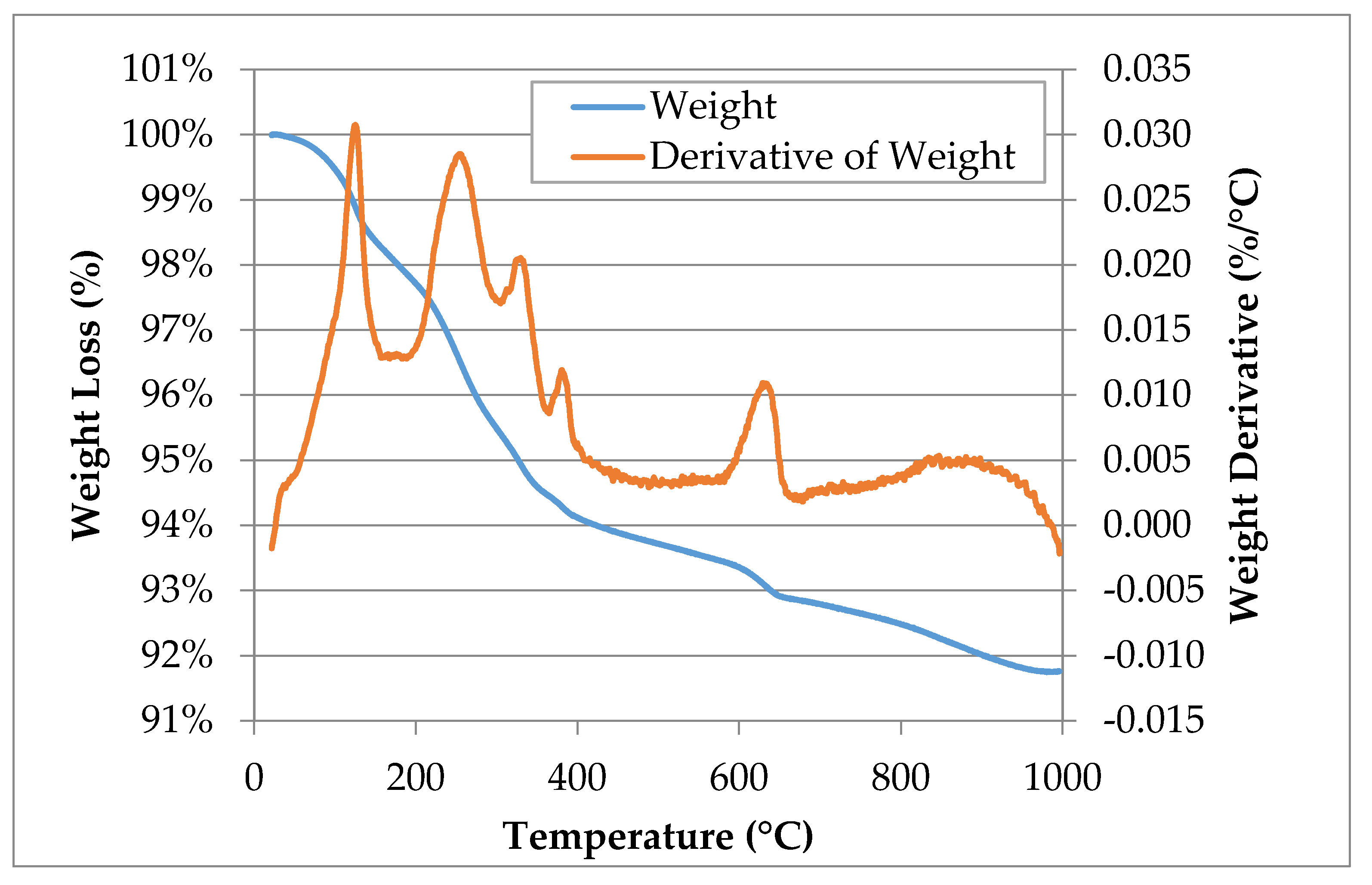
Likewise, additional quantification of the LMF slag composition was conducted using thermogravimetric analysis (TGA), which has been commonly utilized to better assess the total calcium oxide (CaO) and calcium hydroxide (Ca(OH)2) contents present in SFS, based on the method proposed by Brand and Roesler [21]. In this study, a TA Instruments Q50 TGA (TA Instruments, New Castle, DE, USA) was utilized, which heated the sample to 1000 °C at a heating rate of 10 °C per minute to derive the weight loss. Nitrogen was used as the purge gas at flow rates of 60 mL/min for the sample purge and 40 mL/min for the balance purge.
Complexometric titration was utilized to determine the free lime content. In this technique, a sample of SFS is mixed with hot ethylene glycol, filtered, and then titrated with acid after an indicator has been added. Ethylene glycol extraction methods were originally developed to rapidly determine the free lime content of Portland cement and clinker [63], but have since been adopted for SFS (e.g., References [64,65,66,67]). Specifically, the method from Brand and Roesler [21,68] was followed: about 1 g of SFS passing the No. 100 sieve (≤150 μm) was weighed and continuously stirred with 50 mL of ethylene glycol in a water bath at 95 ± 5 °C for 30 min. After filtering, 10 drops of a phenolphthalein indicator were added and then titrated with 0.1 N hydrochloric acid (HCl). The “ethylene glycol number” (EGN) is calculated as follows based on the initial mass of the SFS sample (m), the normality of the HCl (NHCl), the volume of HCl titrated (VHCl), a correction for the volume of HCl titrated in a blank ethylene glycol sample (Vblank), and an equivalency factor (F).
EGN = F [ N H C l ( V H C l V b l a n k ) 10   m ]
The correction factor F for this method is 28 [21,69,70]. The correction Vblank is specified in other standards [71] to account for the amount of HCl needed to titrate a plain solvent sample (i.e., plain ethylene glycol). It was found that Vblank = 0 mL, which is a reasonable result since the pH of ethylene glycol is close to neutral. The EGN value accounts for the available Ca2+ ions from the free CaO and Ca(OH)2, so the free lime content needs to be adjusted based on the Ca(OH)2 determined by TGA [21].
Furthermore, the experimental design consisted of five total mixtures to be compacted at optimum moisture content, including the unmodified and SFS-stabilized clay. Moisture-density relationships were conducted to determine the optimum moisture content for the unmodified clay and the two SFS content mixtures (10% and 15% by weight). Based on the literature review, it was deemed that calcium chloride (CaCl2) may act as a suitable accelerator for the dicalcium silicate phase in the SFS. Therefore, additional mixtures at 10% and 15% SFS were made with 2% CaCl2 (by weight of total water). All five mixtures were then tested for unconfined compressive strength and dynamic modulus.

2.3. Moisture-Density Relationships

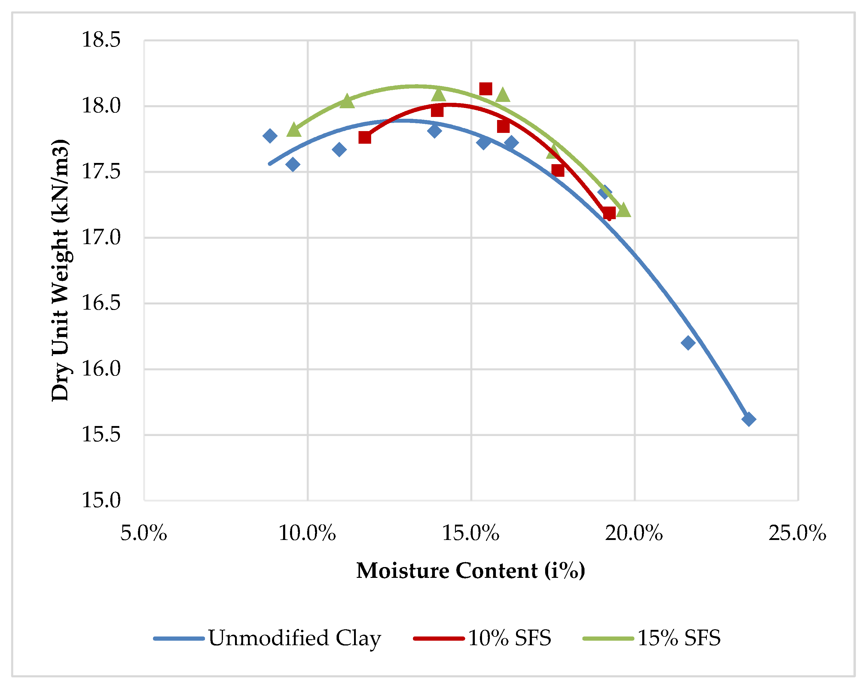
The standard Proctor test according to ASTM D698 was employed to determine the moisture-density relationship for unmodified clay and the clay samples modified with 10% and 15% SFS by weight. The materials were compacted at different moisture contents until the maximum dry density was achieved. The mixing was carried out using a mechanical mixer to accomplish uniform mixing. The compacted samples were weighed and recovered for determining actual moisture content. The optimum moisture content corresponding to maximum dry density was then estimated using the moisture density curves.

2.4. Unconfined Compressive Strength (UCS)

To evaluate the suitability of using the SFS modified mixtures in subgrade stabilization, it is important to quantify the effects of these stabilizers on the sample strength gain characteristics in comparison to unmodified clay strength properties. For this purpose, an unconfined compressive test for the unmodified clay was carried out using ASTM D2166, which was followed by testing the SFS-modified mixtures using ASTM D5102. This is for determining the UCS of compacted soil-lime mixtures.
The mold used for preparing the samples was 2.8 inches (7 cm) in diameter with a height of 5.6 inches (14 cm) with a diameter to height ratio of 1:2. The samples were compacted in the mold at the optimum moisture content to achieve the maximum dry density. The maximum dry density and optimum moisture content information was also employed to determine the exact weight of clay, SFS, and water to result in a specimen of required dimensions as mentioned above. The specimen was compacted into three equal layers.
The unmodified sample was tested immediately after compaction, whereas the modified specimens were wrapped in plastic to avoid moisture loss and then subjected to accelerated curing at 49 °C for 48 h. The accelerated curing used for this research has been tested as equivalent to the 28-day strength of soil-lime mixtures at 23 °C [72,73]. The cured samples were tested for unconfined compressive strength at a displacement rate of 1.0 mm/min. The test performed was stress controlled. The peak load measured was recorded as the unconfined compressive strength.

2.5. Vibration Resonance

In addition to the UCS testing, the improvement to the properties of the soil with the addition of SFS was also investigated by studying the dynamic modulus of the compacted soil. One such method of measuring the dynamic modulus is by vibration resonance. An impact event, when incident on a specimen of finite size, will generate various waves in the specimen, namely primary, secondary, and surface waves. The multiple reflections of the primary and secondary waves will eventually set up a vibration resonance in the sample, which is a function of the dynamic modulus and density of that material [74]. Since the vibration resonance acts to “homogenize” the specimen, the test method can be applied to heterogeneous materials to determine the dynamic modulus, provided that the size of the specimen is larger than the constituents. The dynamic modulus (Ed) can be computed based on the density (ρ), length (L), and fundamental longitudinal frequency (fl) of the specimen as follows.
E d = ρ ( 2 f l L ) 2
Vibration resonance testing, while more commonly applied to concrete materials according to ASTM C215, has been applied to both stabilized and un-stabilized soils [75,76,77,78,79,80]. Guimond-Barrett et al. [75] found repeatable resonance tests between multiple specimens of soil-cement mixtures, which indicates that it is useful for such heterogeneous materials as stabilized soils. A good agreement was reached between the resonant frequency dynamic modulus measured in the laboratory and the modulus measured in the field [76]. In addition, Hilbrich and Scullion [77] determined that a reasonable agreement existed between the resonant frequency dynamic modulus and the resilient modulus of stabilized soils.
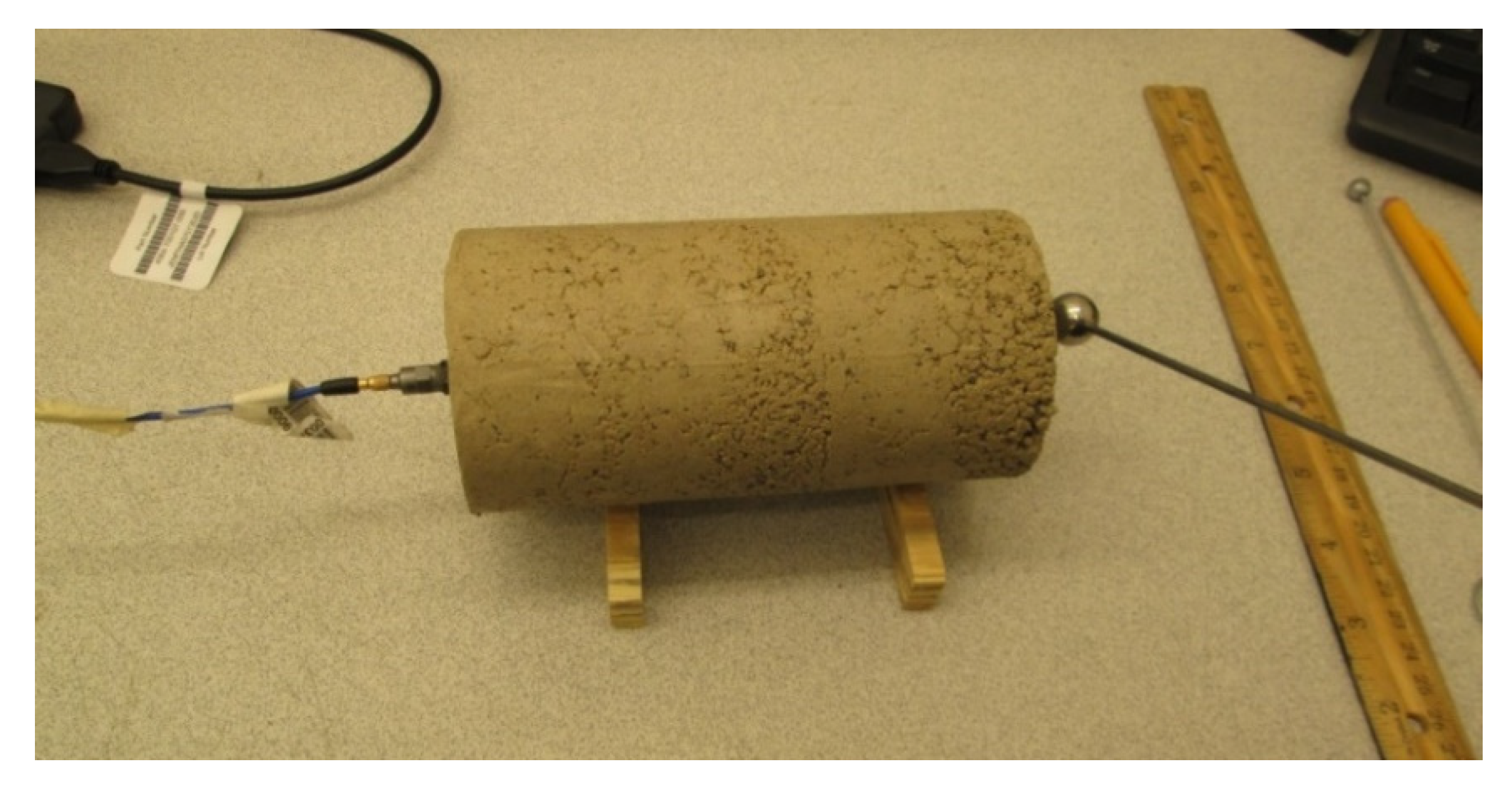
In this laboratory experiment, a compacted cylindrical specimen for the unstabilized and stabilized clay mixtures were tested for longitudinal resonance using three impactor sizes (8, 14, and 18 mm). The experiment configuration followed ASTM C215 for the support arrangement, impact location, and accelerometer location (Figure 1). The accelerometer voltage and time were recorded and post-processed by a fast Fourier transform (FFT) algorithm and plotted in the frequency domain to determine the resonance frequency. For each signal, 50,000 data points were collected with a sample interval of 2 μs for a spectral line spacing of 10 Hz.

3. Results and Discussion

3.1. Characterization of LMF Slag

In accordance with standards, the averages of three replicate gradation tests performed on the LMF slag fines and the fine clayey soil are illustrated in Table 1. The standard deviation was ≤2.3% for the replicate gradation measurements. The LMF slag had 100% passing the No. 4 (4.75 mm) sieve with about 11% passing the No. 200 (75 μm) sieve. The clayey soil had about 15% passing the No. 200 (75 μm) sieve. Table 1 indicates that the clayey soil had a finer gradation than the LMF slag, as was expected. Additionally, the LL, PL, and PI results of the clayey soil are summarized in Table 2. With about 15% of the material passing the No. 200 (75 μm) sieve, the clayey soil is characterized as an AASHTO A-2-6 soil.
Table 3 displays the specific gravity (GS) and absorption of the LMF slag fines, as the average of three replicate tests. Oven dry (OD) and saturated surface dry (SSD) moisture conditions were assessed for the relative GS. Typically, steel slags have higher GS values due to the presence of iron content. The specific gravity of SFS aggregates can be around 3.2 to 3.5 [81]. The absorption was relatively high for the LMF slag fines due to production and processing. Typical SFS absorption values have been reported to be around 0.2% to 1.0% [82].
Mineralogical characterizations of the LMF slag and the clayey soil using XRD are summarized in Table 4. Qualitative analysis of the XRD revealed the presence of wüstite (FeO), larnite (β-dicalcium silicate, Ca2SiO4), mayenite (Ca12Al14O33), and periclase (MgO) in the LMF slag. Recent research by Brand and Roesler [21,55] also revealed that larnite and wüstite are common mineral phases in any steel slag type (EAF, BOF, and LMF slags), which is also consistent with Motz and Geiseler [17]. While phases like mayenite and periclase or magnesium oxide (MgO) are mostly seen in EAF slags, the LMF slag also show only the presence of both oxides [18,83]. The clayey soil was also characterized by XRD. It was indicated that the soil primarily consisted of quartz (SiO2) and kaolinite (Al2Si2O5(OH)4).
Table 5 lists the corresponding identified phases while Figure 2 illustrates the graphical representation of the TGA result of SFS. The total content of a given phase was determined stoichiometrically based on weight loss. The identified mass loss phases included free and chemically-bound water, magnesium hydroxide (Mg(OH)2), calcium hydroxide (Ca(OH)2), and calcium carbonate (CaCO3). From Figure 2, the decomposition of Mg(OH)2, Ca(OH)2, and CaCO3 lies at an approximate temperature of 330 °C, 400 °C, and 600–650 °C, respectively, which agree with the ranges reported in the literature [21,66,84].
The result of the complexometric titration indicated that the free lime content of the LMF slag was about 2.5% (Table 6)). Coupled with the 1.3% Ca(OH)2, 3.2% Mg(OH)2, and an unknown amount of free MgO, there are multiple phases in this LMF slag sample that can contribute to soil stabilization mechanisms.

3.2. Moisture-Density Relationships

The standard Proctor test was used to determine the moisture density relationship for unmodified clay and clays modified with 10% SFS and 15% SFS by weight of the total mix. Figure 3 shows the moisture-density results of the different clay samples. Table 7 summarizes the optimum moisture contents and corresponding maximum dry densities for the unmodified and the SFS-modified clay samples. The values suggest that, as the amount of SFS is increased, the optimum moisture to achieve the maximum dry density is also increased possibly as a result of the high absorption capacity of the SFS. In addition, the maximum dry density was also observed to increase with growing SFS content, which is likely due to the SFS having a higher specific gravity than the clay.

3.3. Unconfined Compressive Strength (UCS)

Three replicate UCS tests were performed for each of the five mixes. The unmodified clay samples were tested immediately after compaction. It was assumed that the addition of the CaCl2 did not affect the optimum moisture content, so these specimens were mixed at the optimum moisture content determined for the SFS mixtures without CaCl2. The SFS-modified samples and SFS-modified samples with CaCl2 were tested after curing for 48 h at 49 °C. An increase in average UCS was observed with growing SFS content. However, the addition of CaCl2 in SFS-modified clay samples showed a reduction in the UCS compared to the equivalent SFS-modified samples without CaCl2, which was also shown by Thomas [85]. Meanwhile, the UCS for SFS modified clay with CaCl2 was greater than unmodified clay, as observed in the work of Poh et al. [45].
Figure 4 shows the comparison of three replicates tested for each mixture. Table 8 summarizes the values measured for UCS for different mixtures. The results indicate that there was variability in UCS and the displacement at peak load in the three replicates. However, the displacement at peak load was not necessarily differentiated between the unmodified and SFS-modified clay samples. The average UCS for each mixture is shown in Figure 5, which indicates that the SFS-modified clay samples had greater standard deviations than the unmodified clay. This suggests that there was greater variability in the chemical reactions and/or compaction.
Despite accounting for the moisture content of the clay and SFS, it can be observed in Table 8 that the actual moisture at compaction was higher than the optimum moisture content. This can contribute to the variability in the findings since not all samples were, therefore, compacted to maximum density [33].
The stress-displacement curves for the various mixtures and replicates are shown in the Supplementary Material (Figure S1), with averages compared in Figure 6. The stress-displacement behavior suggests that the modulus of the stabilized clay samples is greater than the unmodified clay. Estimating the elastic modulus based on the linear portion of the stress-strain curves reveals that the elastic modulus for the different mixes follows the same trend as with UCS, as demonstrated in Figure 7. However, it is noted that the CaCl2 addition did not affect the elastic modulus relative to the 10% SFS mix, but the limited dataset for the 10% SFS mix may skew this finding. The addition of 10% SFS increased the elastic modulus by 60% while 15% SFS increased the elastic modulus by 75%, relative to the unmodified clay.

3.4. Vibration Resonance

For the unmodified clay, the longitudinal resonant frequency was found to be more repeatable (coefficient of variation of 1.3%) when compared to the transverse resonant frequency (coefficient of variation of 3.1%), as can be seen in Table 9. The larger impactors generated a transverse resonant frequency that was lower than that generated by the small impactor, which is unexpected since the resonant frequency is a fundamental material property and should not change. This finding suggests that the unmodified clay has a damping effect that influences the resonant frequency. The possible damping effect of the clay may have been a factor for previous studies that determined the longitudinal resonant frequency [75,76,77]. Comparing the impactor size (see Supplementary Material, Figure S2), it is evident that the small impactor induced the most prominent response. The larger impactors additionally induced some noise in the signal before the resonant frequency for both the longitudinal and transverse testing.
Given the higher variability in the transverse resonant frequency, only the longitudinal resonant frequency was determined for the stabilized mixtures along with the corresponding dynamic modulus (Table 10). As shown in Table 10, the longitudinal resonant frequency was higher for the stabilized mixtures when compared to the unmodified clay, which resulted in higher dynamic moduli for the stabilized mixtures (Figure 8). Relative to the unmodified clay, the increases in dynamic modulus were 212%, 221%, 139%, and 105% for the stabilized mixes with 10% SFS, 15% SFS, 10% SFS with CaCl2, and 15% SFS with CaCl2, respectively. Comparing the stabilized mixes with and without CaCl2, the CaCl2 was not effective at accelerating the hydration or the reaction of the SFS.
Note that the dynamic modulus from resonance testing was significantly greater than the estimated elastic modulus from the UCS tests. This is an expected outcome, as has been demonstrated for various geomaterials [86,87,88,89,90] because of differences in strain rate, material heterogeneity and the volume probed, anisotropic effects, stress history, and strain amplitude. For instance, the static elastic modulus testing in this study involved large strains relative to the comparatively small strains in resonant frequency dynamic modulus testing. It was found that the dynamic modulus was 2.5–6 times greater than the estimated elastic modulus.

3.5. Effect of SFS Content

A general trend of increasing UCS and dynamic modulus was noted with increasing SFS content, which suggests that: (1) the CaO and Ca(OH)2 content of the SFS is reacting with the clay and/or (2) the SFS particles are physically acting to stabilize the soil structure. Certainly the chemical reaction between lime and clay minerals will enhance the engineering properties of the soil [91,92]. However, the total CaO and Ca(OH)2 content of the LMF slag was about 3.5%, which may not be sufficient to be the sole cause of the increase in strength and modulus. Therefore, it is likely that the SFS also contributes a mechanical stabilization or modification of the soil, as has been demonstrated in the literature using other aggregates [93,94,95,96].
Figure 9 also demonstrates that the dynamic and elastic (static) moduli increased with increasing SFS content, with the dynamic modulus increasing more than the elastic modulus. As discussed in Section 3.4, the dynamic and elastic moduli are not equivalent, as demonstrated in other studies [86,87,88,89,90], with the dynamic modulus often being a greater magnitude than the elastic modulus [86]. Therefore, the moduli behavior in Figure 9 is in agreement with the literature.
As shown in Figure 9, the dataset suggests that a linear trend matches the increase in properties at least up to 15% SFS. However, the dataset is too limited to definitively assess and characterize the relationship between the SFS content and the hardened properties of the stabilized clay.

3.6. Effect of CaCl2 Addition

Relative to the SFS-modified clay samples, the addition of the CaCl2 reduced the UCS and dynamic modulus of the stabilized clay. With 10% SFS, the addition of CaCl2 reduced the dynamic modulus by 23% while, with 15% SFS, the reduction was 36% when CaCl2 was added. Taylor [97] reports that the accelerating effect of CaCl2 is more pronounced for Portland cement at lower temperatures. Therefore, perhaps, the elevated curing temperature adversely affected the accelerating ability of the CaCl2. In addition, while the use of chloride salts appears to enhance the reaction of lime with clayey soils [98,99,100], it is possible that the elevated curing temperature accelerated the carbonation of the free CaO in the SFS [101], which could have, therefore, negated the effectiveness of chloride in accelerating the lime-clay reaction. It has also been reported that the calcium silicate phase(s) in SFS are poorly reactive or relatively inert [81,102], which would additionally suggest that the CaCl2 did not sufficiently affect the SFS reactivity.

4. Conclusions

The study was undertaken to investigate the potential for stabilizing a clayey soil with steel furnace slag (SFS). The SFS employed was specifically a finely graded ladle metallurgy furnace (LMF) slag. The LMF slag was found to be composed of wüstite, larnite (β-dicalcium silicate), mayenite, and periclase with approximately 2.5% free lime, 1.3% calcium hydroxide, and 3.2% magnesium hydroxide. The soil, selected for its plastic properties, was a refractory clay composed of quartz and kaolinite and was classified as an AASHTO A-2-6 soil with a plasticity index of 14.
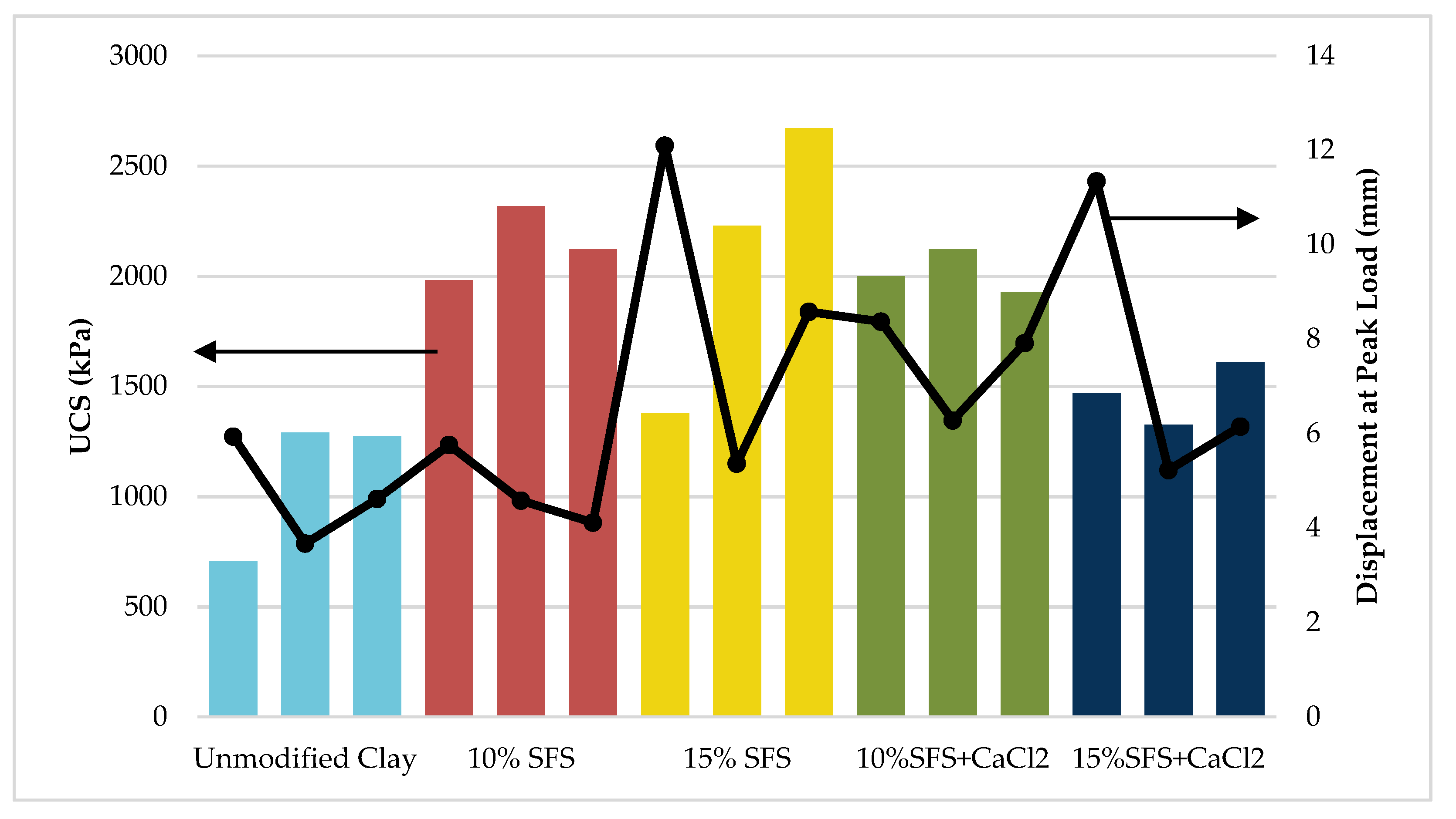
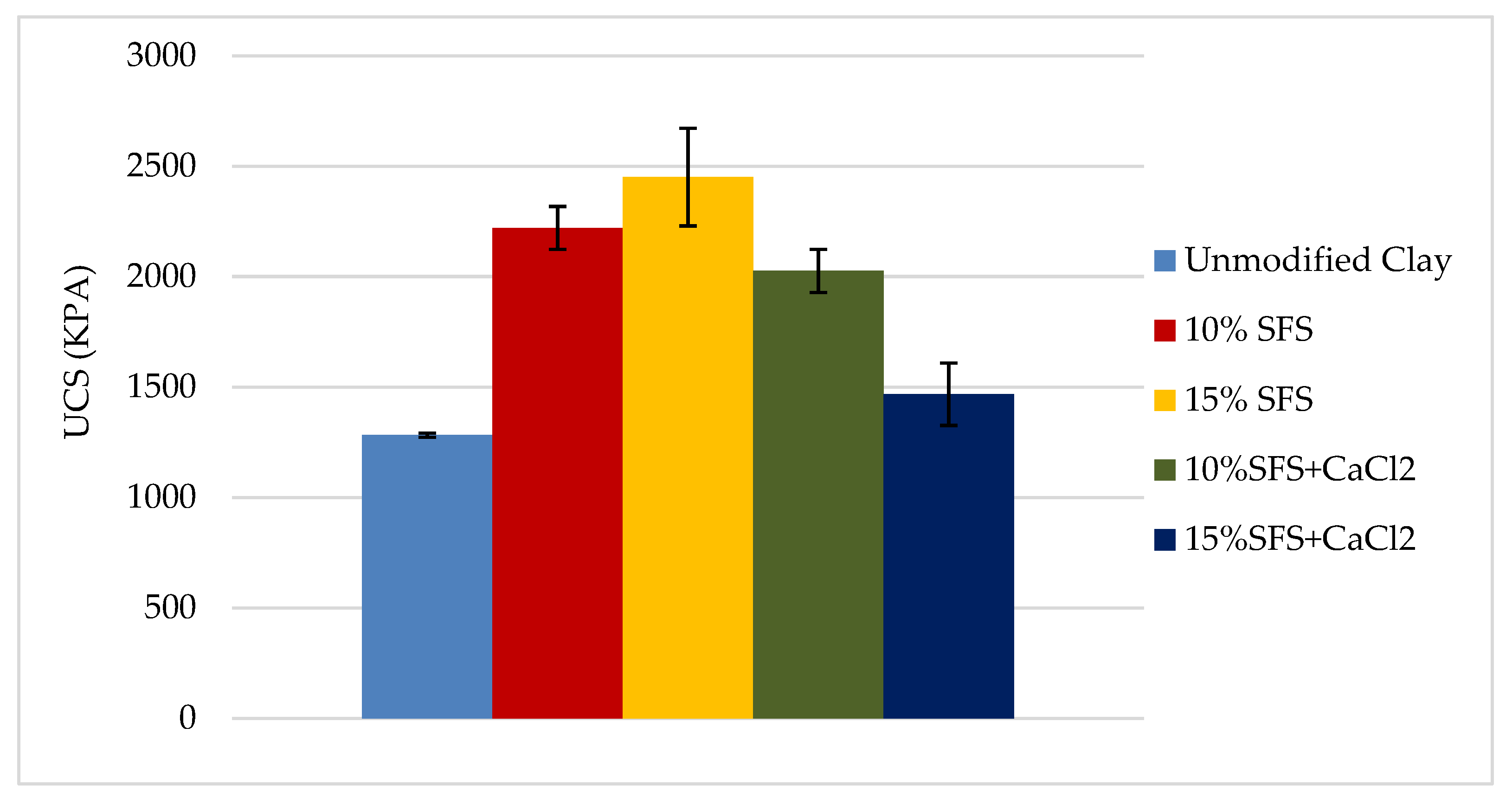
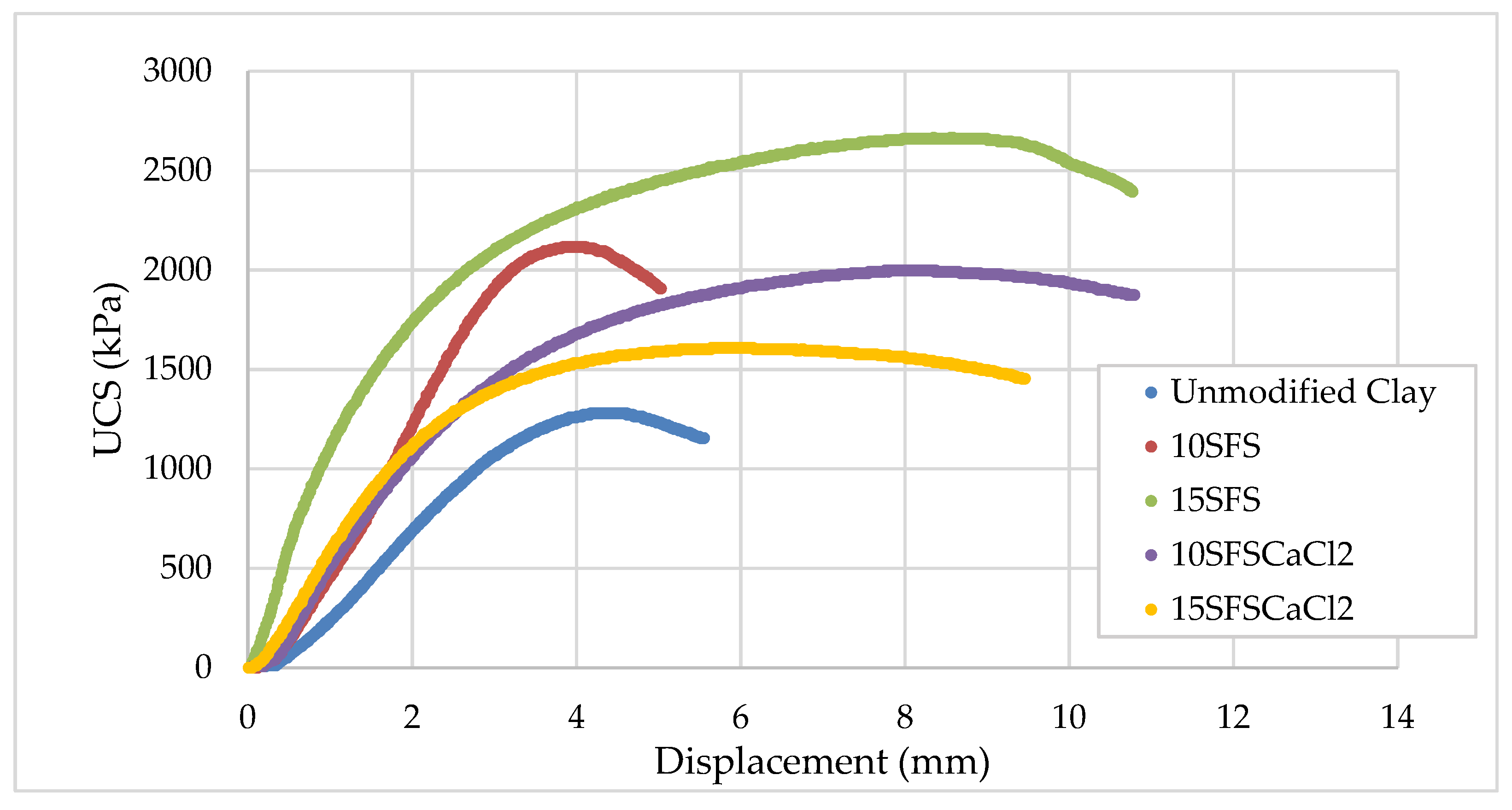
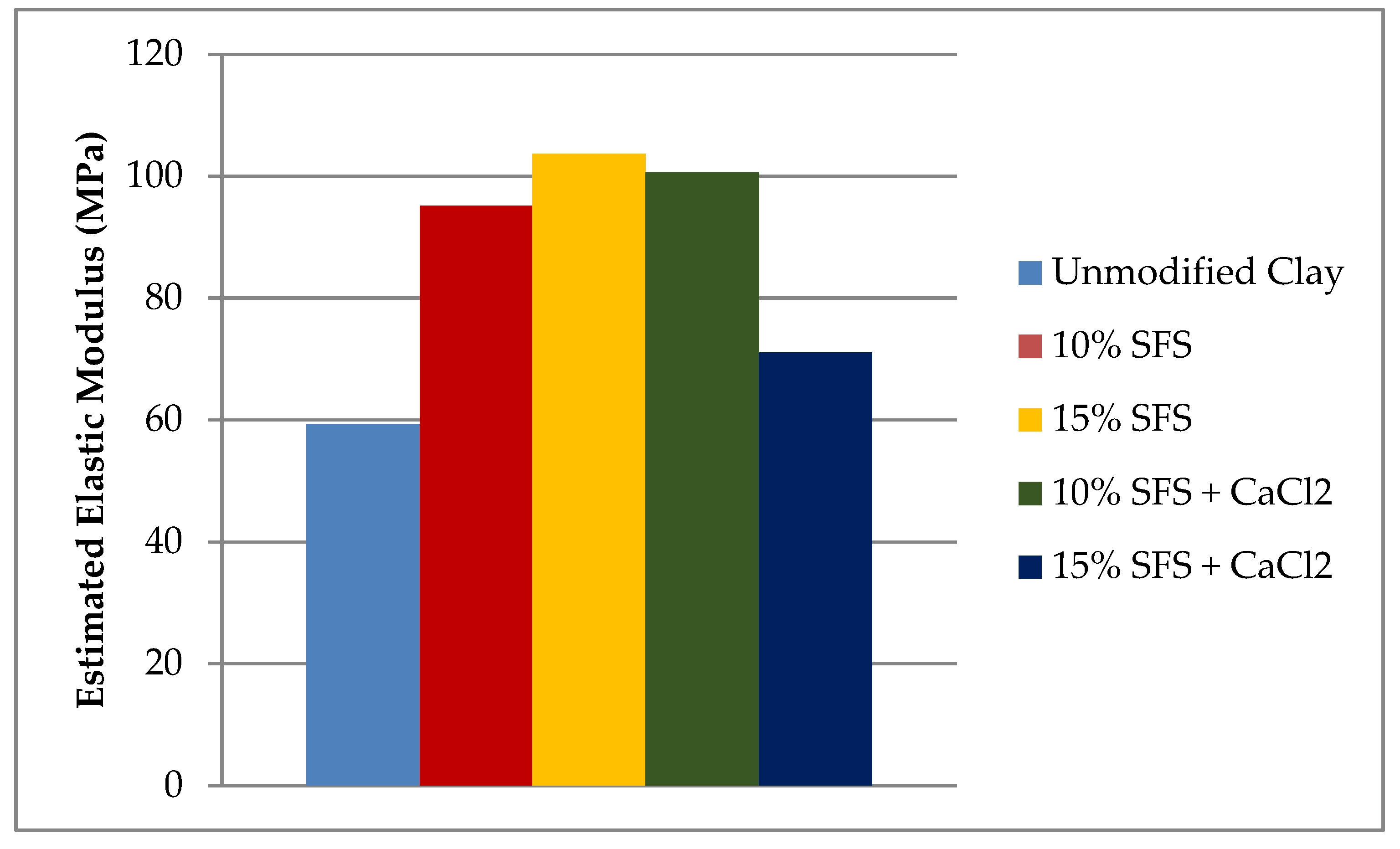
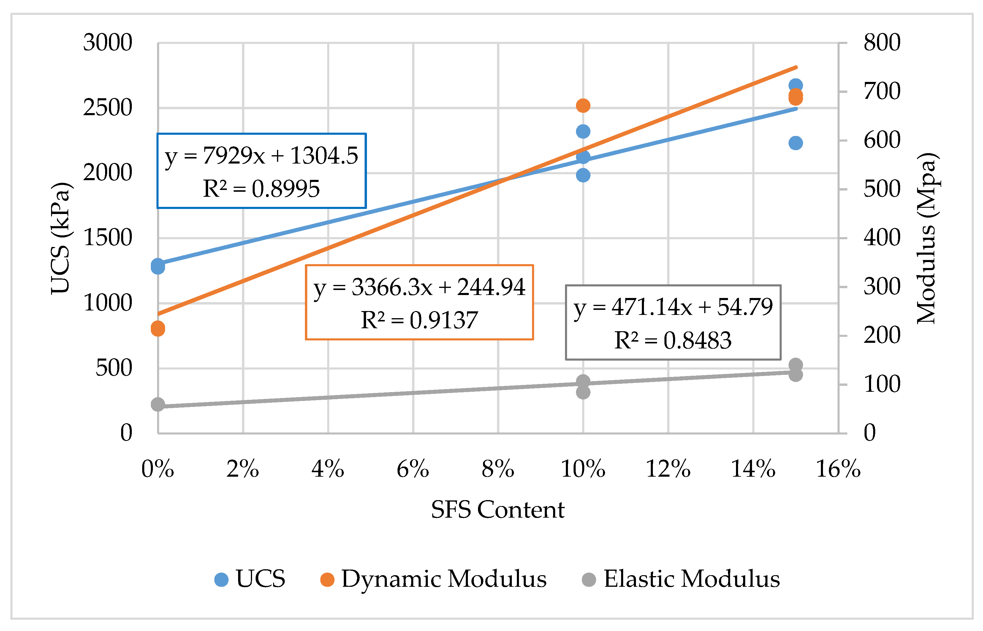
Two SFS contents were tested, which included 10% and 15% LMF slag by weight. The moisture-density relationships revealed that the maximum dry density and optimum moisture content increased with increasing SFS content. The results indicated a linear trend for increasing unconfined compressive strength (UCS) and dynamic modulus with increasing SFS content. Relative to the unmodified clay, the UCS increased by 67% and 91% when 10% and 15% SFS were utilized, respectively. The elastic modulus increased by 60% and 75% when 10% and 15% SFS were used, respectively, and the dynamic modulus increased by 212% and 221% when 10% and 15% SFS were added, respectively. Based on the literature, additional SFS modified samples were created with calcium chloride added at 2% by weight of the total water in an attempt to accelerate the hydration of the dicalcium silicate in the LMF slag, but the results suggested that calcium chloride was not effective.
These findings suggest that LMF slag fines are suitable for stabilizing clayey soils. While there was insufficient evidence of a chemical stabilization mechanism, it is likely that the SFS at least contributed to a mechanical stabilization mechanism. The results also indicate that 15% SFS provides the most improvement to the UCS and dynamic modulus of the stabilized soil, even though further testing is required to validate and improve upon these findings.

Supplementary Materials

The following are available online at https://www.mdpi.com/1996-1944/13/19/4251/s1. Figure S1: Stress-displacement curves for the five mixtures and replicates. Figure S2: Longitudinal resonance for the un-stabilized clay for each impactor size. Figure S3: Comparison of the longitudinal resonant frequency responses generated with 8-mm impactor for each mix. Table S1: UCS and elastic modulus data for each replicate. Table S2: Replicate test data for longitudinal resonance frequency. Table S3: Replicate test data for transverse resonance frequency. Table S4: Moisture-density data from Proctor tests.

Author Contributions

Conceptualization, A.S.B. Methodology, A.S.B. and P.S. Formal analysis, A.S.B., P.S., and E.O.F. Investigation, A.S.B. and P.S. Resources, E.T. Data curation, A.S.B. and P.S. Writing—original draft preparation, A.S.B., P.S., and E.O.F. Writing—review and editing, A.S.B., P.S., E.O.F., and E.T. Supervision, E.T. All authors have read and agreed to the published version of the manuscript.

Funding

This research received no external funding.

Acknowledgments

The authors would like to thank Vincent Mwumvaneza and Erin Curtis for their assistance and John Yzenas of Edw. C. Levy Co. for providing the LMF slag. The XRD and TGA were carried out in part in the Frederick Seitz Materials Research Laboratory Central Research Facilities, University of Illinois. The authors would like to acknowledge the Virginia Tech Open Access Subvention Fund for their financial assistance with the open access article processing charges.

Conflicts of Interest

The authors declare no conflict of interest.

References

  1. Knodel, P.C. Characteristics and Problems of Dispersive Clay Soils; Report No. R-91-09; U.S. Bureau of Reclamation: Denver, CO, USA, 1991.
  2. Wagner, J.-F. Mechanical properties of clays and clay minerals. In Handbook of Clay Science; Bergaya, F., Lagaly, G., Eds.; Elsevier: Amsterdam, The Netherlands, 2013; pp. 347–381. [Google Scholar]
  3. Bell, F.G. Engineering Properties of Soil and Rocks, 4th ed.; Blackwell Science: Malden, MA, USA, 1999. [Google Scholar]
  4. Gutiérrez, F.; Desir, G.; Gutiérrez, M. Causes of the catastrophic failure of an earth dam built on gypsiferous alluvium and dispersive clays (Altorricón, Huesca Province, NE Spain). Environ. Geol. 2003, 43, 842–851. [Google Scholar] [CrossRef]
  5. Ramalho-Ortigão, J.A.; Werneck, M.L.G.; Lacerda, W.A. Embankment failure on clay near Rio de Janeiro. J. Geotech. Eng. 1983, 109, 1460–1479. [Google Scholar] [CrossRef]
  6. Fletcher, L.; Hungr, O.; Evans, S.G. Contrasting failure behaviour of two large landslides in clay and silt. Can. Geotech. J. 2002, 39, 46–62. [Google Scholar] [CrossRef] [Green Version]
  7. Petry, T.M.; Little, D.N. Review of stabilization of clays and expansive soils in pavements and lightly loaded structures—History, practice, and future. J. Mater. Civ. Eng. 2002, 14, 447–460. [Google Scholar] [CrossRef]
  8. Ikeagwuani, C.C.; Nwonu, D.C. Emerging trends in expansive soil stabilisation: A review. J. Rock Mech. Geotech. Eng. 2019, 11, 423–440. [Google Scholar] [CrossRef]
  9. Rafalko, S.D.; Filz, G.M.; Brandon, T.L.; Mitchell, J.K. Rapid chemical stabilization of soft clay soils. Transp. Res. Rec. 2007, 2026, 39–46. [Google Scholar] [CrossRef] [Green Version]
  10. Wilkinson, A.; Haque, A.; Kodikara, J. Stabilisation of clayey soils with industrial by-products: Part A. Proc. Inst. Civ. Eng. Improv. 2010, 163, 149–163. [Google Scholar] [CrossRef]
  11. Wilkinson, A.; Haque, A.; Kodikara, J. Stabilisation of clayey soils with industrial by-products: Part B. Proc. Inst. Civ. Eng. Improv. 2010, 163, 165–172. [Google Scholar] [CrossRef]
  12. Nidzam, R.M.; Kinuthia, J.M. Sustainable soil stabilisation with blastfurnace slag—A review. Proc. Inst. Civ. Eng. Mater. 2010, 163, 157–165. [Google Scholar] [CrossRef]
  13. James, J.; Kasinatha Pandian, P. Industrial wastes as auxiliary additives to cement/lime stabilization of soils. Adv. Civ. Eng. 2016, 2016, 1267391. [Google Scholar] [CrossRef] [Green Version]
  14. Jalal, F.E.; Xu, Y.; Jamhiri, B.; Memon, S.A. On the recent trends in expansive soil stabilization using calcium-based stabilizer materials (CSMs): A comprehensive review. Adv. Mater. Sci. Eng. 2020, 2020, 1510969. [Google Scholar] [CrossRef] [Green Version]
  15. Shi, C. Steel slag—Its production, processing, characteristics, and cementitious properties. J. Mater. Civ. Eng. 2004, 16, 230–236. [Google Scholar] [CrossRef]
  16. Wang, G.C. The Utilization of Slag in Civil Infrastructure Construction; Woodhead Publishing: Cambridge, UK, 2016. [Google Scholar]
  17. Motz, H.; Geiseler, J. Products of steel slags an opportunity to save natural resources. Waste Manag. 2001, 21, 285–293. [Google Scholar] [CrossRef]
  18. Yildirim, I.Z.; Prezzi, M. Chemical, mineralogical, and morphological properties of steel slag. Adv. Civ. Eng. 2011, 2011. [Google Scholar] [CrossRef] [Green Version]
  19. Balcázar, N.; Kühn, M.; Baena, J.M.; Formoso, A.; Piret, J. Summary report on RTD in iron and steel slags: Development and perspectives. In Proceedings No. EUR 19066 EN; European Commission: Luxembourg, 1999. [Google Scholar]
  20. Van Oss, H.G. Slag—Iron and steel. In 2017 Minerals Yearbook; U.S. Geological Survey: Reston, VA, USA, 2017; pp. 69.1–69.8. [Google Scholar]
  21. Brand, A.S.; Roesler, J.R. Steel furnace slag aggregate expansion and hardened concrete properties. Cem. Concr. Compos. 2015, 60, 1–9. [Google Scholar] [CrossRef]
  22. Deniz, D.; Tutumluer, E.; Popovics, J.S. Evaluation of expansive characteristics of reclaimed asphalt pavement and virgin aggregate used as base materials. Transp. Res. Rec. 2010, 2167, 10–17. [Google Scholar] [CrossRef]
  23. Dayioglu, A.Y.; Aydilek, A.H.; Cetin, B. Preventing swelling and decreasing alkalinity of steel slags used in highway infrastructures. Transp. Res. Rec. 2014, 2401, 52–57. [Google Scholar] [CrossRef]
  24. Senior, S.A.; Szoke, S.I.; Rogers, C.A. Ontario’s experience with reclaimed materials for use as aggregates. In Proceedings of the Transportation Association of Canada (TAC) Conference, Calgary, AB, Canada, 3–7 July 1994; Volume 6, pp. A31–A56. [Google Scholar]
  25. Erlin, B.; Jana, D. Forces of hydration that can cause havoc in concrete. Concr. Int. 2003, 25, 51–57. [Google Scholar]
  26. Crawford, C.B.; Burn, K.N. Building damage from expansive steel slag backfill. J. Soil Mech. Found. Div. 1969, 95, 1325–1334. [Google Scholar]
  27. Gnaedinger, J.P. Open hearth slag—A problem waiting to happen. J. Perform. Constr. Facil. 1987, 1, 78–83. [Google Scholar] [CrossRef]
  28. Armaghani, J.M.; Larsen, T.J.; Smith, L.L. Design related distress in concrete pavements. Concr. Int. 1988, 10, 43–49. [Google Scholar]
  29. Cherian, C.; Arnepalli, D.N. A critical appraisal of the role of clay mineralogy in lime stabilization. Int. J. Geosynth. Gr. Eng. 2015, 1, 8. [Google Scholar] [CrossRef] [Green Version]
  30. Jha, A.K.; Sivapullaiah, P.V. Lime stabilization of soil: A physico-chemical and micro-mechanistic perspective. Indian Geotech. J. 2020, 50, 339–347. [Google Scholar] [CrossRef]
  31. Diamond, S.; Kinter, E.B. Mechanisms of soil-lime stabilization: An interpretive review. Highw. Res. Rec. 1965, 92, 83–102. [Google Scholar]
  32. Aldeeky, H.; Al Hattamleh, O. Experimental study on the utilization of fine steel slag on stabilizing high plastic subgrade soil. Adv. Civ. Eng. 2017, 2017. [Google Scholar] [CrossRef]
  33. Asghari-Kaljahi, E.; Hosseinzadeh, Z.; Mansouri, H. Treatment of clayey soils with steel furnace slag and lime for road construction in the South West of Iran. In Recent Thoughts in Geoenvironmental Engineering; Ameen, H., Jamiolkowski, M., Manassero, M., Shehata, H., Eds.; Springer: Berlin/Heidelberg, Germany, 2019; pp. 68–78. [Google Scholar]
  34. Chan, C.-M.; Mizutani, T.; Kikuchi, Y. Reusing dredged marine clay by solidification with steel slag: A study of compressive strength. Int. J. Civ. Struct. Eng. 2011, 2, 270–279. [Google Scholar]
  35. Chan, C.-M.; Jalil, A.N.A. Some insights to the reuse of dredged marine soils by admixing with activated steel slag. Adv. Civ. Eng. 2014, 2014, 345134. [Google Scholar] [CrossRef] [Green Version]
  36. Manso, J.M.; Ortega-López, V.; Polanco, J.A.; Setién, J. The use of ladle furnace slag in soil stabilization. Constr. Build. Mater. 2013, 40, 126–134. [Google Scholar] [CrossRef]
  37. Shen, J.; Xu, Y.; Chen, J.; Wang, Y. Study on the stabilization of a new type of waste solidifying agent for soft soil. Materials 2019, 12, 826. [Google Scholar] [CrossRef] [Green Version]
  38. Xu, B.; Yi, Y. Soft clay stabilization using ladle slag-ground granulated blastfurnace slag blend. Appl. Clay Sci. 2019, 178, 105136. [Google Scholar] [CrossRef]
  39. Shalabi, F.I.; Asi, I.M.; Qasrawi, H.Y. Effect of by-product steel slag on the engineering properties of clay soils. J. King Saud Univ. Eng. Sci. 2017, 29, 394–399. [Google Scholar] [CrossRef] [Green Version]
  40. Ashango, A.A.; Patra, N.R. Behavior of expansive soil treated with steel slag, rice husk ash, and lime. J. Mater. Civ. Eng. 2016, 28, 6016008. [Google Scholar] [CrossRef]
  41. Ismail, A.I.M.; Awad, S.A.; Mwafy, M.A.G. The utilization of electric arc furance slag in soil improvement. Geotech. Geol. Eng. 2019, 37, 401–411. [Google Scholar] [CrossRef]
  42. Akinwumi, I. Soil modification by the application of steel slag. Period. Polytech. Civ. Eng. 2014, 58, 371–377. [Google Scholar] [CrossRef] [Green Version]
  43. Akinmusuru, J.O. Potential beneficial uses of steel slag wastes for civil engineering purposes. Resour. Conserv. Recycl. 1991, 5, 73–80. [Google Scholar] [CrossRef]
  44. Yildirim, I.Z.; Prezzi, M.; Vasudevan, M.; Santoso, H. Use of Soil-Steel Slag-Class-C Fly Ash Mixtures in Subgrade Applications; Report FHWA/IN/JTRP-2013/06; Joint Transportation Research Program: West Lafayette, IN, USA, 2013. [Google Scholar]
  45. Poh, H.Y.; Ghataora, G.S.; Ghazireh, N. Soil stabilization using basic oxygen steel slag fines. J. Mater. Civ. Eng. 2006, 18, 229–240. [Google Scholar] [CrossRef]
  46. Baghabra Al-Amoudi, O.S.; Al-Homidy, A.A.; Maslehuddin, M.; Saleh, T.A. Method and mechanisms of soil stabilization using electric arc furnace dust. Sci. Rep. 2017, 7, 46676. [Google Scholar] [CrossRef] [Green Version]
  47. Zumrawi, M.M.E.; Babikir, A.A.-A.A. Laboratory study of steel slag used for stabilizing expansive soil. Asian Eng. Rev. 2017, 4, 1–6. [Google Scholar] [CrossRef]
  48. Mirzaeifar, H.; Abdi, M.R. Stabilizing clays using basic oxygen steel slag (BOS). In Recent Research, Advances and Execution Aspects of Ground Improvement Works; Denies, N., Huybrechts, N., Eds.; International Society for Soil Mechanics and Geotechnical Engineering: Brussels, Belgium, 2012; Volume II, pp. 403–410. [Google Scholar]
  49. Abdi, M.R. Effects of basic oxygen steel slag (BOS) on strength and durability of kaolinite. Int. J. Civ. Eng. 2011, 9, 81–89. [Google Scholar]
  50. Wang, Q.; Yan, P. Hydration properties of basic oxygen furnace steel slag. Constr. Build. Mater. 2010, 24, 1134–1140. [Google Scholar] [CrossRef]
  51. Belhadj, E.; Diliberto, C.; Lecomte, A. Characterization and activation of basic oxygen furnace slag. Cem. Concr. Compos. 2012, 34, 34–40. [Google Scholar] [CrossRef]
  52. Shi, C. Characteristics and cementitious properties of ladle slag fines from steel production. Cem. Concr. Res. 2002, 32, 459–462. [Google Scholar] [CrossRef]
  53. Montenegro, J.M.; Celemín-Matachana, M.; Cañizal, J.; Setién, J. Ladle furnace slag in the construction of embankments: Expansive behavior. J. Mater. Civ. Eng. 2013, 25, 972–979. [Google Scholar] [CrossRef]
  54. Setién, J.; Hernández, D.; González, J.J. Characterization of ladle furnace basic slag for use as a construction material. Constr. Build. Mater. 2009, 23, 1788–1794. [Google Scholar] [CrossRef]
  55. Brand, A.S.; Roesler, J.R. Interfacial transition zone of cement composites with steel furnace slag aggregates. Cem. Concr. Compos. 2018, 86, 117–129. [Google Scholar] [CrossRef]
  56. World Steel Association. World Steel in Figures; World Steel Association: Brussels, Belgium, 2019. [Google Scholar]
  57. Mindess, S.; Francis, Y.J.; Darwin, D. Concrete, 2nd ed.; Prentice Hall: Upper Saddle River, NJ, USA, 2003. [Google Scholar]
  58. Muhmood, L.; Vitta, S.; Venkateswaran, D. Cementitious and pozzolanic behavior of electric arc furnace steel slags. Cem. Concr. Res. 2009, 39, 102–109. [Google Scholar] [CrossRef]
  59. Mahieux, P.Y.; Aubert, J.E.; Escadeillas, G.; Measson, M. Quantification of hydraulic phase contained in a basic oxygen furnace slag. J. Mater. Civ. Eng. 2014, 26, 593–598. [Google Scholar] [CrossRef]
  60. Murphy, J.N.; Meadowcroft, T.R.; Barr, P.V. Enhancement of the cementitious properties of steelmaking slag. Can. Metall. Q. 1997, 36, 315–331. [Google Scholar] [CrossRef]
  61. Adolfsson, D.; Robinson, R.; Engström, F.; Björkman, B. Influence of mineralogy on the hydraulic properties of ladle slag. Cem. Concr. Res. 2011, 41, 865–871. [Google Scholar] [CrossRef]
  62. Conjeaud, M.; George, C.M.; Sorrentino, F.P. A new steel slag for cement manufacture: Mineralogy and hydraulicity. Cem. Concr. Res. 1981, 11, 85–102. [Google Scholar] [CrossRef]
  63. Gebhardt, R.F. Rapid Methods for Chemical Analysis of Hydraulic Cement; American Society for Testing and Materials: West Conshohocken, PA, USA, 1988. [Google Scholar]
  64. Lee, H.-S.; Lim, H.-S.; Ismail, M.A. Quantitative evaluation of free CaO in electric furnace slag using the ethylene glycol method. Constr. Build. Mater. 2017, 131, 676–681. [Google Scholar] [CrossRef]
  65. Kneller, W.A.; Gupta, J.; Borkowski, M.L.; Dollimore, D. Determination of original free lime content of weathered iron and steel slags by thermogravimetric analysis. Transp. Res. Rec. 1994, 1434, 17–22. [Google Scholar]
  66. Gupta, J.D.; Kneller, W.A.; Tamirisa, R.; Skrzypczak-Jankun, E. Characterization of base and subbase iron and steel slag aggregates causing deposition of calcareous tufa in drains. Transp. Res. Rec. 1994, 1434, 8–16. [Google Scholar]
  67. Coomarasamy, A.; Walzak, T.L. Effects of moisture on surface chemistry of steel slags and steel slag-asphalt paving mixes. Transp. Res. Rec. 1995, 1492, 85–95. [Google Scholar]
  68. Brand, A.S.; Roesler, J.R. Expansive and concrete properties of SFS–FRAP aggregates. J. Mater. Civ. Eng. 2016, 28, 1–10. [Google Scholar] [CrossRef]
  69. Chandru, P.; Karthikeyan, J.; Natarajan, C. Steel slag—A strong and sustainable substitute for conventional concreting materials. In Sustainable Materials in Building Construction; Springer: Berlin/Heidelberg, Germany, 2020; pp. 31–76. [Google Scholar]
  70. Javellana, M.P.; Jawed, I. Extraction of free lime in portland cement and clinker by ethylene glycol. Cem. Concr. Res. 1982, 12, 399–403. [Google Scholar] [CrossRef]
  71. British Standards Institute. BS EN 1744-1 Tests for Chemical Properties of Aggregates. Part 1: Chemical Analysis; British Standards Institute: London, UK, 2013. [Google Scholar]
  72. Anday, M.C. Accelerated curing for lime-stabilized soils. Highw. Res. Board Bull. 1961, 304, 1–13. [Google Scholar]
  73. Thompson, M.R. Mixture design for lime-treated soils. Ill. Univ. Hwy. Res. Lab. Civ. Eng. Stud. 1969, 26. [Google Scholar]
  74. Malhotra, V.M. Nondestructive tests. In Significance of Tests and Properties of Concrete and Concrete-Making Materials; ASTM International: West Conshohocken, PA, USA, 2006. [Google Scholar]
  75. Guimond-Barrett, A.; Nauleau, E.; Le Kouby, A.; Pantet, A.; Reiffsteck, P.; Martineau, F. Free-Free resonance testing of in situ deep mixed soils. Geotech. Test. J. 2013, 36, 283–291. [Google Scholar] [CrossRef]
  76. Nazarian, S.; Yuan, D.; Tandon, V. Structural field testing of flexible pavement layers with seismic methods for quality control. Transp. Res. Rec. 1999, 1654, 50–60. [Google Scholar] [CrossRef]
  77. Hilbrich, S.L.; Scullion, T. Rapid alternative for laboratory determination of resilient modulus input values on stabilized materials for AASHTO mechanistic-empirical design guide. Transp. Res. Rec. 2007, 2026, 63–69. [Google Scholar] [CrossRef]
  78. Åhnberg, H.; Holmén, M. Assessment of stabilised soil strength with geophysical methods. Proc. Inst. Civ. Eng. Improv. 2011, 164, 109–116. [Google Scholar] [CrossRef]
  79. Le Kouby, A.; Guimond-Barrett, A.; Reiffsteck, P.; Pantet, A. Influence of drying on the stiffness and strength of cement-stabilized soils. Geotech. Geol. Eng. 2018, 36, 1463–1474. [Google Scholar] [CrossRef]
  80. Toohey, N.M.; Mooney, M.A. Seismic modulus growth of lime-stabilised soil during curing. Geotechnique 2012, 62, 161–170. [Google Scholar] [CrossRef]
  81. Emery, J.J. Slag utilization in pavement construction. In Extending Aggregate Resources; ASTM Special Technical Publication 774; American Society for Testing and Materials: Philadelphia, PA, USA, 1982. [Google Scholar]
  82. Geiseler, J. Use of steelworks slag in Europe. Waste Manag. 1996, 16, 59–63. [Google Scholar] [CrossRef]
  83. Pellegrino, C.; Faleschini, F. Experimental behavior of reinforced concrete beams with electric arc furnace slag as recycled aggregate. ACI Mater. J. 2013, 110, 197–205. [Google Scholar] [CrossRef]
  84. Halikia, I.; Economacou, A. Application of various methods of nonisothermal kinetic analysis to magnesium hydroxide decomposition. Int. J. Chem. Kinet. 1993, 25, 609–631. [Google Scholar] [CrossRef]
  85. Thomas, G.H. Investigations on LD Slag with Particular Reference to Its Use for Road Construction; Report EUR 8622 EN; Commission of the European Communities: Brussels, Belgium, 1983. [Google Scholar]
  86. Fjær, E. Relations between static and dynamic moduli of sedimentary rocks. Geophys. Prospect. 2019, 67, 128–139. [Google Scholar] [CrossRef] [Green Version]
  87. Gheibi, A.; Hedayat, A. The relation between static Young’s modulus and dynamic bulk modulus of granular materials and the role of stress history. In Proceedings of the Geotechnical Earthquake Engineering and Soil Dynamics V, Austin, TX, USA, 10–13 June 2018; pp. 373–382. [Google Scholar]
  88. Tutuncu, A.N.; Podio, A.L.; Gregory, A.R.; Sharma, M.M. Nonlinear viscoelastic behavior of sedimentary rocks, Part I: Effect of frequency and strain amplitude. Geophysics 1998, 63, 184–194. [Google Scholar] [CrossRef]
  89. Fjær, E. Static and dynamic moduli of a weak sandstone. Geophysics 2009, 74, WA103–WA112. [Google Scholar] [CrossRef]
  90. AnhDan, L.Q.; Koseki, J.; Sato, T. Comparison of Young’s moduli of dense sand and gravel measured by dynamic and static methods. Geotech. Test. J. 2002, 25, 349–368. [Google Scholar] [CrossRef]
  91. Bell, F.G. Lime stabilization of clay minerals and soils. Eng. Geol. 1996, 42, 223–237. [Google Scholar] [CrossRef]
  92. Prusinski, J.R.; Bhattacharja, S. Effectiveness of portland cement and lime in stabilizing clay soils. Transp. Res. Rec. 1999, 1652, 215–227. [Google Scholar] [CrossRef]
  93. Mishra, S.; Sachdeva, S.N.; Manocha, R. Subgrade soil stabilization using stone dust and coarse aggregate: A cost effective approach. Int. J. Geosynth. Gr. Eng. 2019, 5, 20. [Google Scholar] [CrossRef]
  94. Soosan, T.G.; Sridharan, A.; Jose, B.T.; Abraham, B.M. Utilization of quarry dust to improve the geotechnical properties of soils in highway construction. Geotech. Test. J. 2005, 28, 391–400. [Google Scholar] [CrossRef]
  95. Okagbue, C.O.; Onyeobi, T.U.S. Potential of marble dust to stabilise red tropical soils for road construction. Eng. Geol. 1999, 53, 371–380. [Google Scholar] [CrossRef]
  96. Igwe, O.; Adepehin, E.J. Alternative approach to clay stabilization using granite and dolerite dusts. Geotech. Geol. Eng. 2017, 35, 1657–1664. [Google Scholar] [CrossRef]
  97. Taylor, H.F.W. Cement Chemistry, 2nd ed.; Thomas Telford: London, UK, 1997. [Google Scholar]
  98. Mohd Yunus, N.Z.; Wanatowski, D.; Marto, A.; Jusoh, S.N. Strength improvement of lime-treated clay with sodium chloride. Geotech. Res. 2017, 4, 192–202. [Google Scholar] [CrossRef] [Green Version]
  99. Davoudi, M.H.; Kabir, E. Interaction of lime and sodium chloride in a low plasticity fine grain soils. J. Appl. Sci. 2011, 11, 330–335. [Google Scholar] [CrossRef]
  100. Lees, G.; Abdelkader, M.O.; Hamdani, S.K. Sodium chloride as an additive in lime-soil stabilization. Highw. Eng. 1982, 29, 2–8. [Google Scholar]
  101. Belhadj, E.; Diliberto, C.; Lecomte, A. Properties of hydraulic paste of basic oxygen furnace slag. Cem. Concr. Compos. 2014, 45, 15–21. [Google Scholar] [CrossRef]
  102. Frías Rojas, M.; Sánchez de Rojas, M.I. Chemical assessment of the electric arc furnace slag as construction material: Expansive compounds. Cem. Concr. Res. 2004, 34, 1881–1888. [Google Scholar] [CrossRef]
Figure 1. Cylindrical specimen and configuration for testing the longitudinal resonance frequency.
Materials 13 04251 g001
Figure 2. TGA result of the LMF slag, which indicates the weight loss and the derivative of the weight loss.
Materials 13 04251 g002
Figure 3. Moisture-density relationships for unmodified clay, and clay modified with 10% SFS, and 15% SFS.
Materials 13 04251 g003
Figure 4. Unconfined compressive strength (UCS) comparison of clay samples.
Materials 13 04251 g004
Figure 5. Average UCS for each mixture. Error bars indicate one standard deviation.
Materials 13 04251 g005
Figure 6. Average stress-displacement curve for each mixture.
Materials 13 04251 g006
Figure 7. Average estimated elastic modulus for each mixture.
Materials 13 04251 g007
Figure 8. Comparison of the dynamic modulus generated by the 8-mm impactor for each mix.
Materials 13 04251 g008
Figure 9. Relationships between UCS and modulus with the SFS content (without CaCl2).
Materials 13 04251 g009
Table 1. Average gradations of the LMF slag and clayey soil.
Sieve SizeAverage Cumulative Percent Passing
USmmLMF SlagClayey Soil
1/4”6.35100.0100.0
#44.75100.0100.0
#82.3699.997.9
#161.1889.283.1
#300.660.466.9
#500.338.242.8
#1000.1521.928.8
#2000.07510.814.6
Table 2. Clayey soil physical properties.
Liquid LimitPlastic LimitPlasticity IndexPercent Passing #200 Sieve
35211414.6%
Table 3. Average GS and absorption values for the LMF slag fines.
Relative GS (OD)Relative GS (SSD)Apparent GSAbsorption (%)
Average value2.5752.7673.1867.46%
Standard deviation0.0180.0170.0180.09%
Table 4. Mineral phases identified by qualitative XRD.
Mineral PhasesLMF SlagFine Clayey Soil
Kaolinite, Al2Si2O5(OH)4 X
Quartz, SiO2 X
Larnite, β-dicalcium silicate, Ca2SiO4X
Periclase, MgOX
Mayenite, Ca12Al14O33X
Wüstite, FeOX
Table 5. Phase identification and content by TGA.
Identified PhasesPeak Decomposition (°C)Mass Loss Range (°C)Mass LossPhase Content
Free water126.689–1551.33%1.33%
Chemically bound water255.6190–3022.39%2.39%
Mg(OH)2332.7302–3620.98%3.18%
Ca(OH)2380.7362–3950.32%1.32%
CaCO3629.0580–6600.57%1.29%
Table 6. Free lime content of the LMF slag fines.
EGN Value from Titration (%)Ca(OH)2 Content from TGA (%)Stoichiometric CaO Content in Ca(OH)2 (%)Estimated Free CaO Content (%)
3.451.321.002.45
Table 7. Optimum moisture content and maximum dry density values for the unmodified and SFS-modified clay.
Mixture TypeOptimum Moisture Content (%)Maximum Dry Density (kg/m3)
Unmodified Clay13.70%17.82
10% SFS14.25%18.01
15% SFS15.00%18.10
Table 8. Values of unconfined compressive strength (UCS), actual moisture, target moisture, and displacement at peak load.
MixOptimum Moisture Content (%)Actual Moisture Content (%)Replicateno.Peak Load (kN)UCS (kPa)Displacement at Peak Load (mm)
Unmodified Clay13.7015.5310.40 *707.45.94
20.731291.43.67
30.721274.24.62
10% SFS14.2518.4611.121981.65.77
21.312318.04.58
31.202122.94.12
15% SFS15.0018.7110.78 *1380.312.10
21.262229.15.37
31.512671.78.58
10% SFS + CaCl214.2517.4811.131585.88.37
21.202122.96.28
31.091928.57.92
15% SFS + CaCl215.0018.2010.831468.611.34
20.751327.25.23
30.911609.96.15
* Data point considered an outlier and not included in the average.
Table 9. Longitudinal and transverse resonant frequencies for the unmodified clay.
Impactor SizeTest ReplicateTransverse Resonant Frequency (Hz)Longitudinal Resonant Frequency (Hz)
8 mm16601130
26701140
36201140
14 mm16601130
26301110
36501100
18 mm16301120
26201140
36201130
Table 10. Longitudinal dynamic modulus for each mixture.
SampleImpactor SizeLength (cm)Density (kg/m3)Average Longitudinal Resonant Frequency (Hz)Average Dynamic Modulus (MPa)
Unmodified Clay8 mm14.22064.01136.7215
14 mm14.22064.01113.3206
18 mm14.22064.01130.0213
10% SFS8 mm14.22101.21990.0671
14 mm14.22101.21950.0644
18 mm14.22101.21966.7656
15% SFS8 mm14.22146.41996.7690
14 mm14.22146.42025.0710
18 mm14.22146.42015.0703
10% SFS + CaCl28 mm14.12097.61755.0514
14 mm14.12097.61765.0520
18 mm14.12097.61753.3513
15% SFS + CaCl28 mm14.12141.91610.0442
14 mm14.12141.91625.0450
18 mm14.12141.91593.3432

