Experimental Study on the Stiffness of Steel Beam-to-Upright Connections for Storage Racking Systems


Abstract
:1. Introduction
2. Materials and Methods
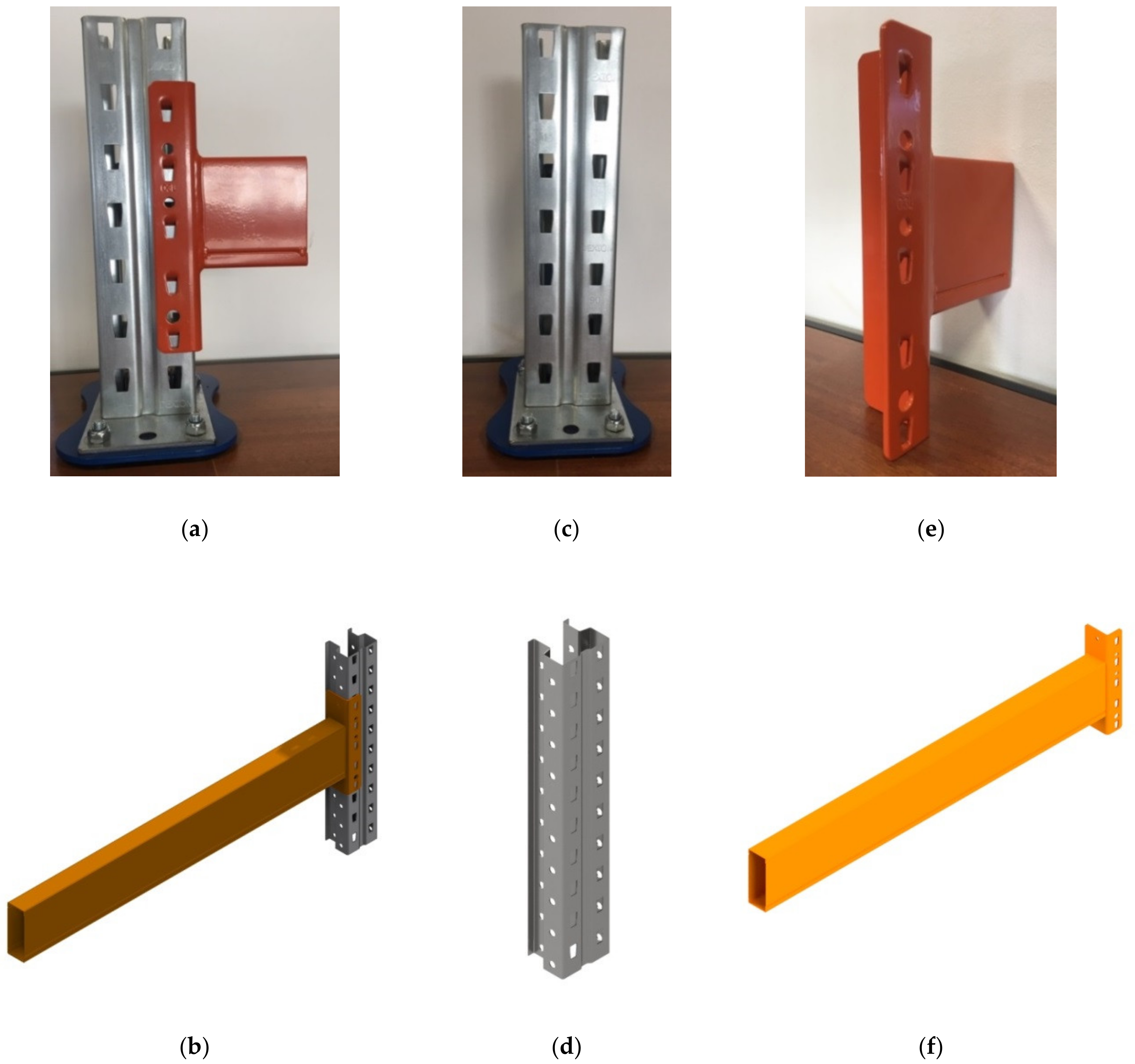
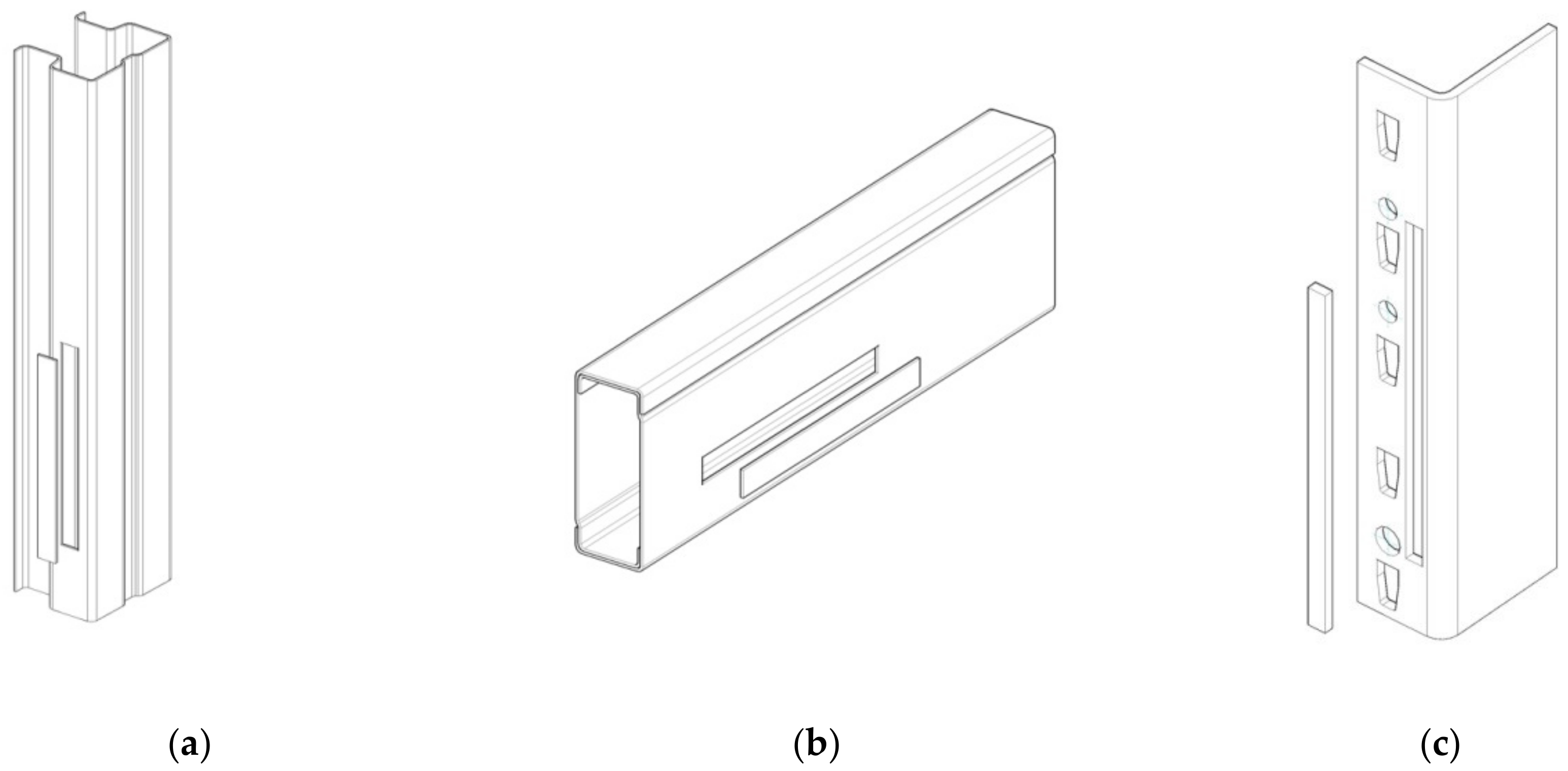
2.1. Beam-to-Upright Connections Tested
2.2. Work Methods
2.2.1. Tensile Tests
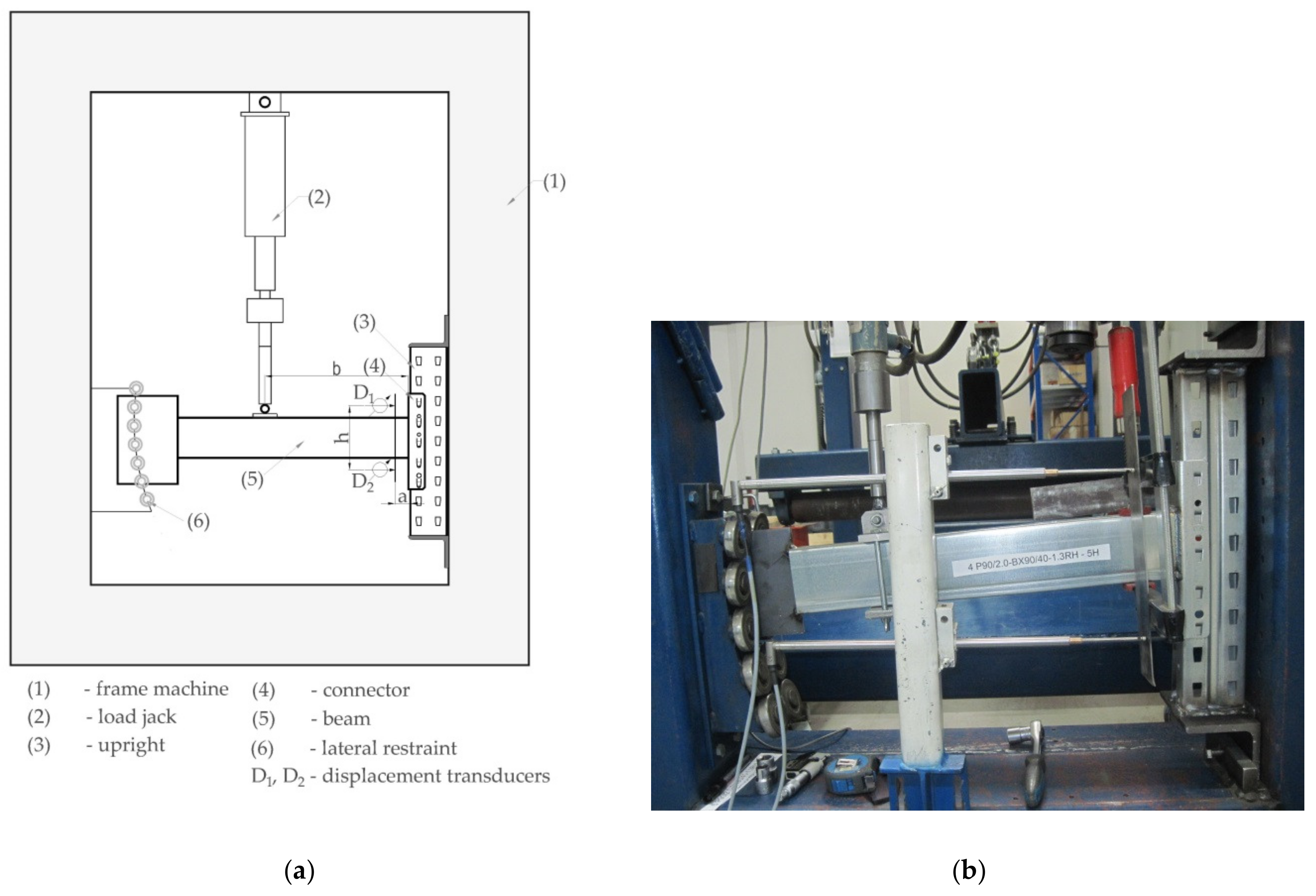
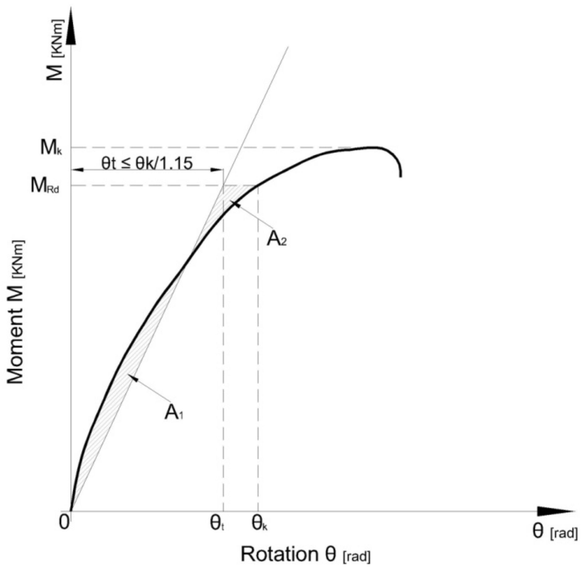
2.2.2. Bending Test of the Connections
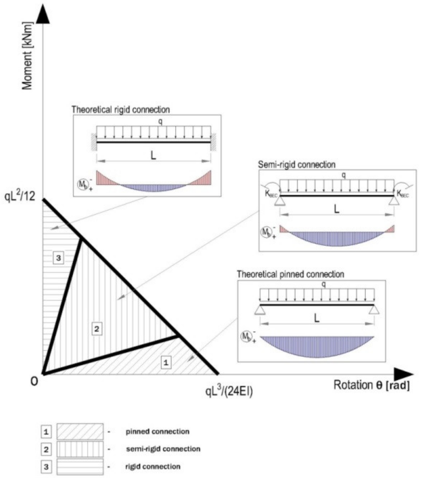
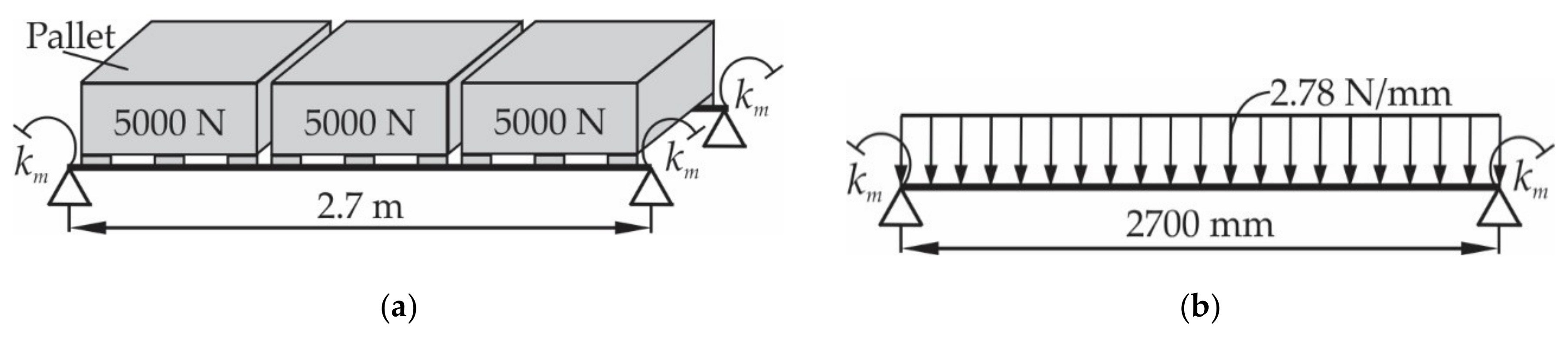
2.2.3. Theoretical Aspects Regarding the Effects of the Stiffness of Connection on Deflections
3. Results
3.1. Tensile Properties of the Materials
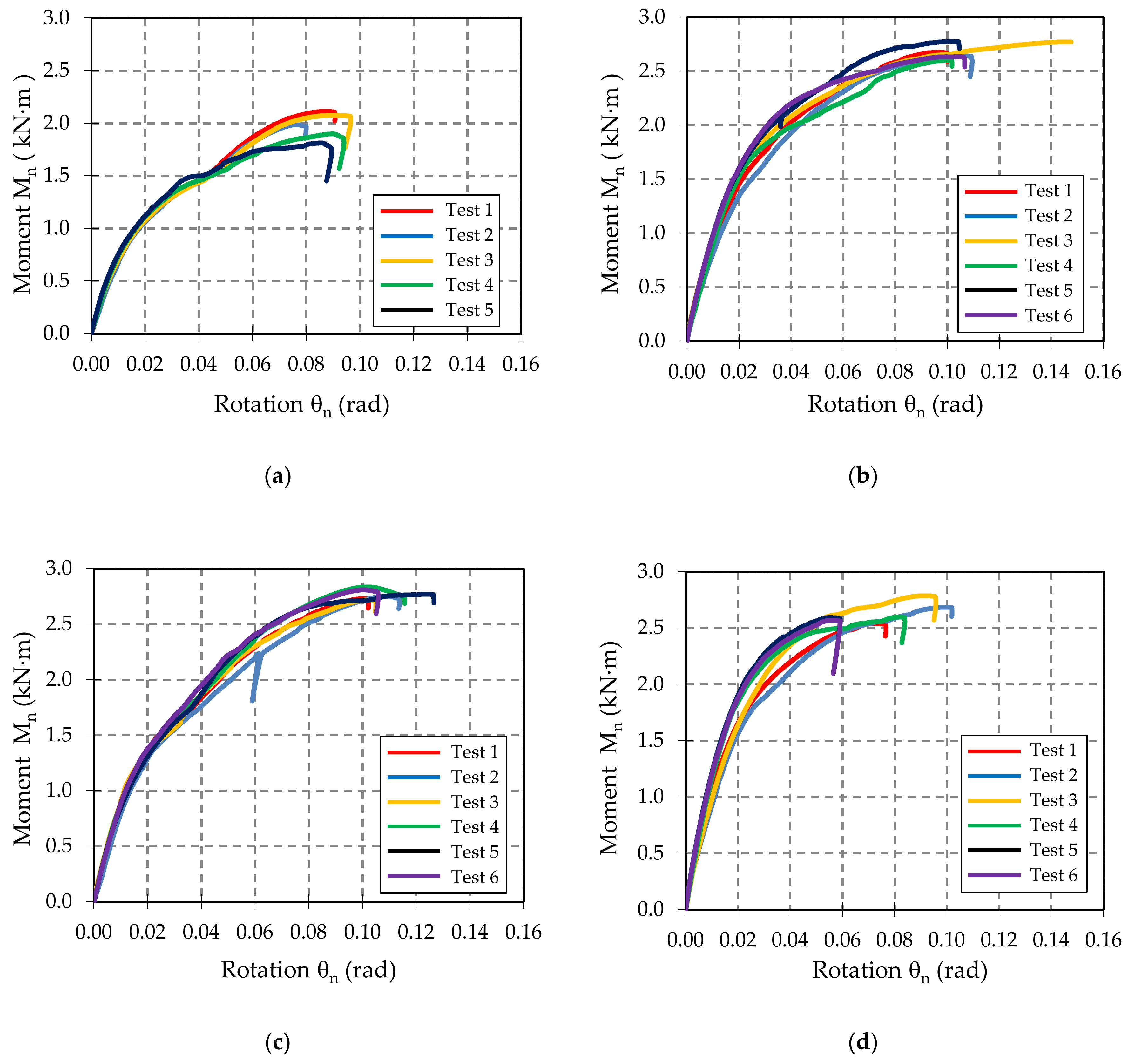
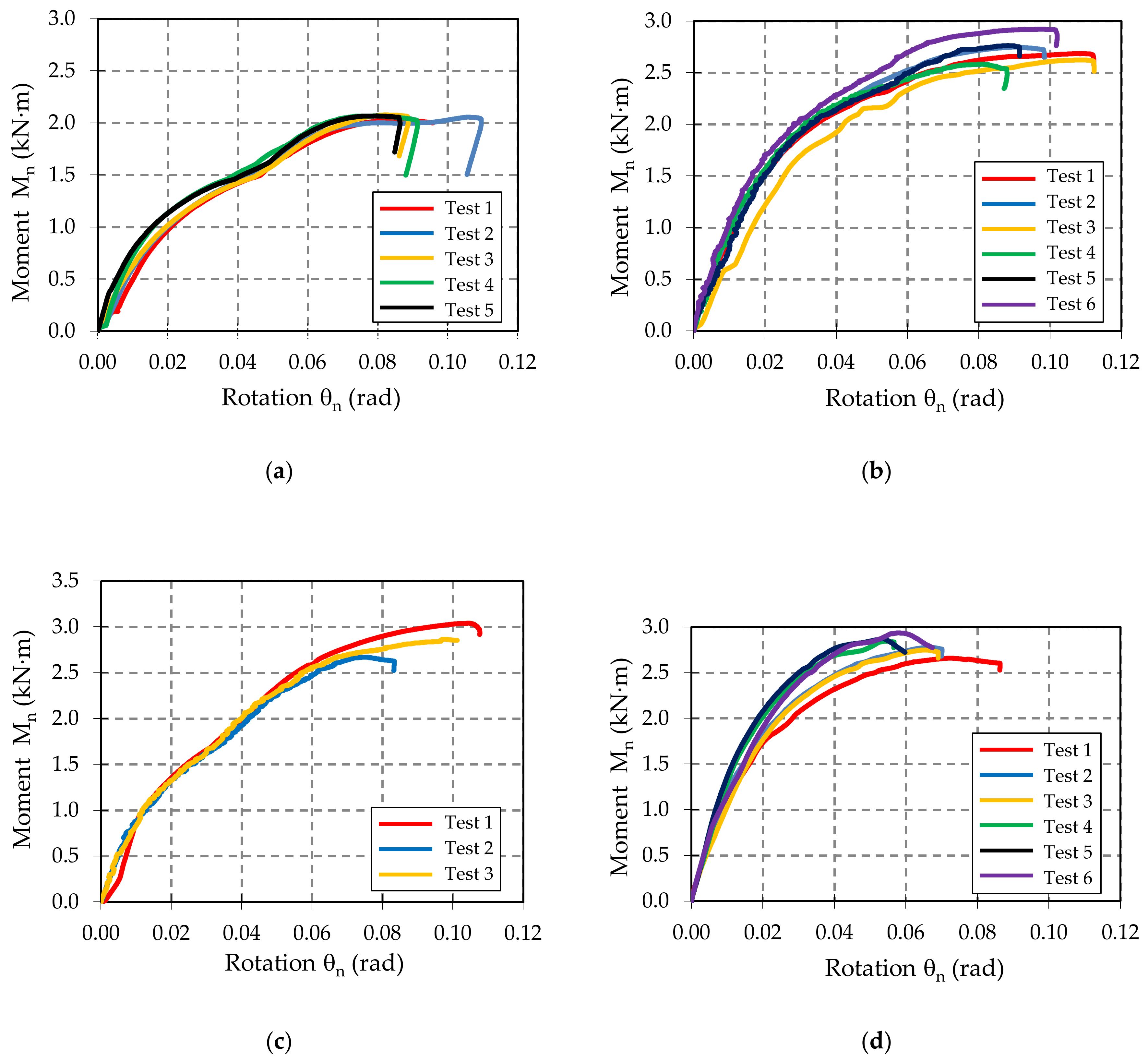
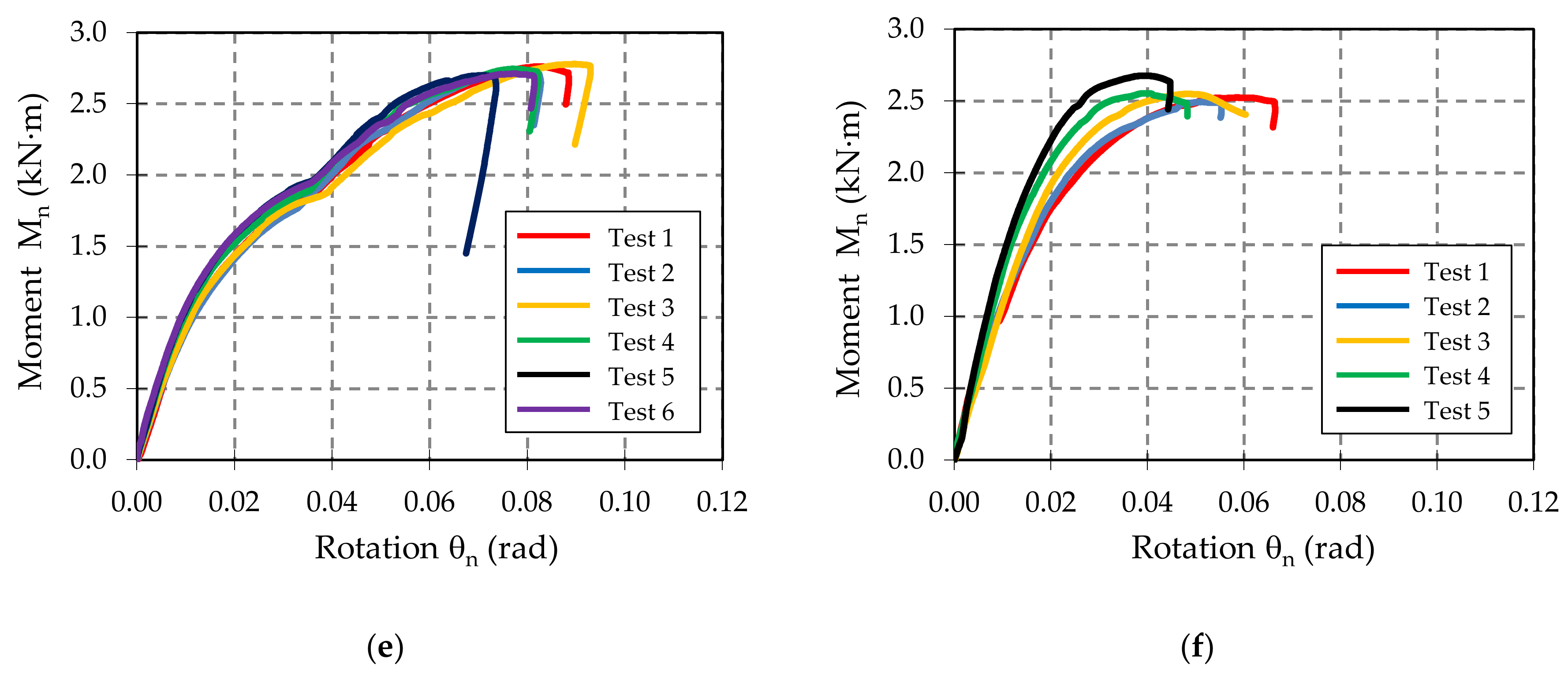
3.2. Results of Bending Tests
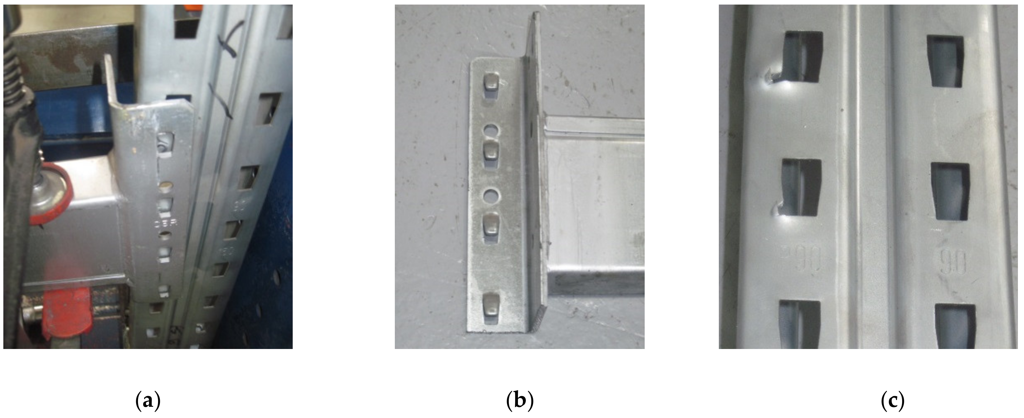
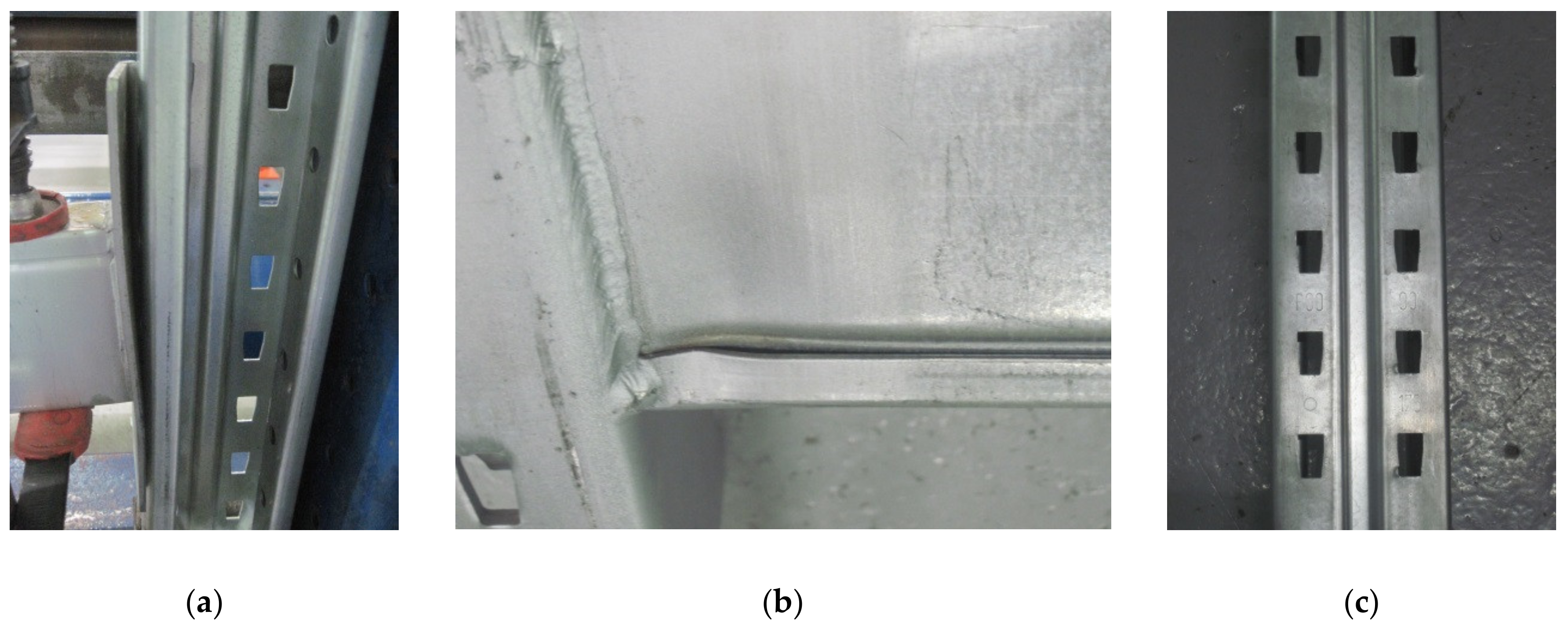
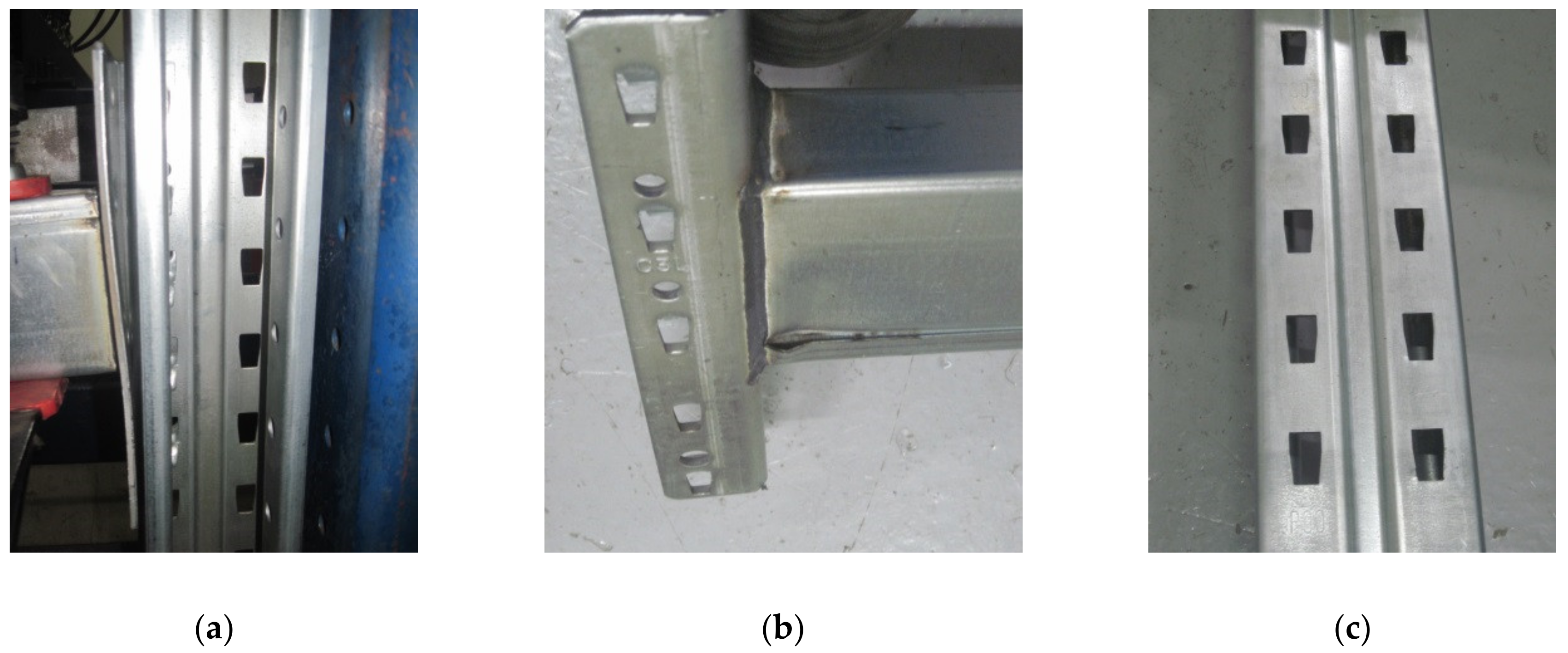
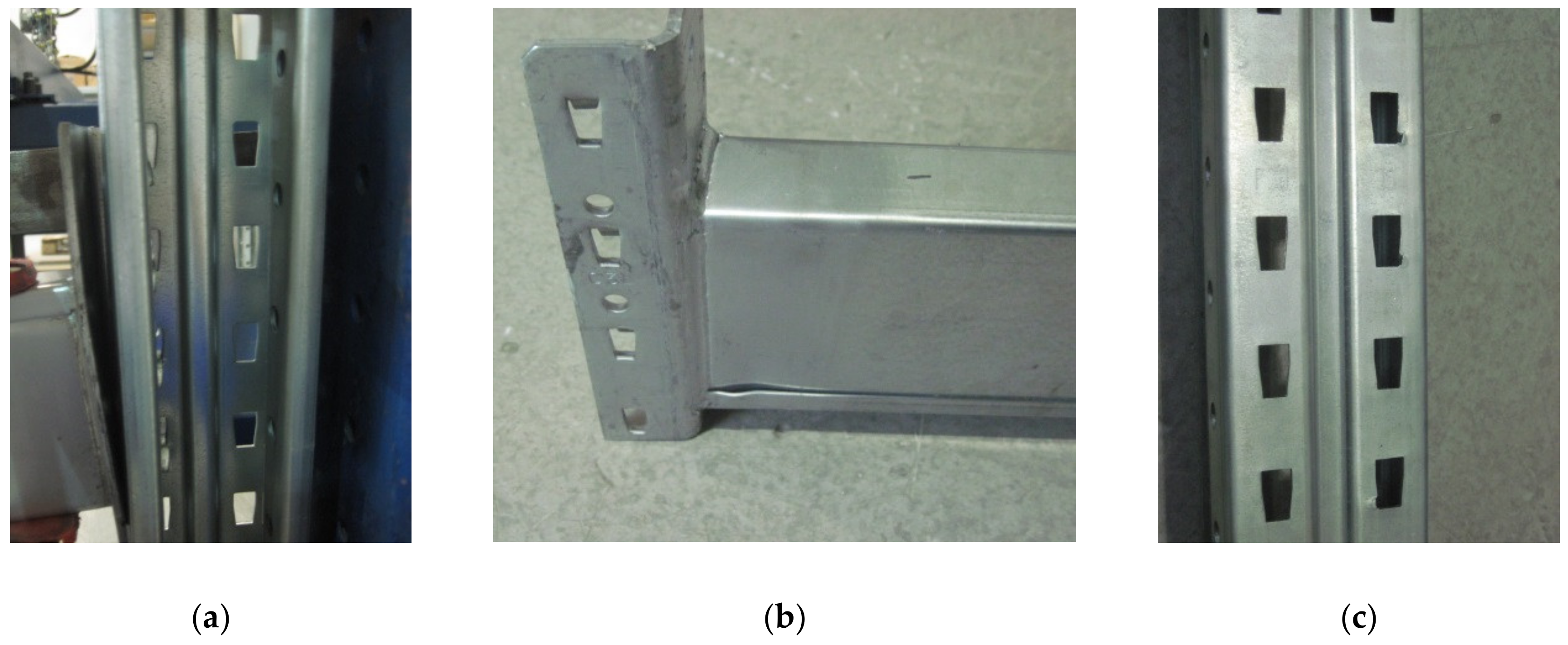
3.3. Failure Modes in Bending Tests
4. Discussion
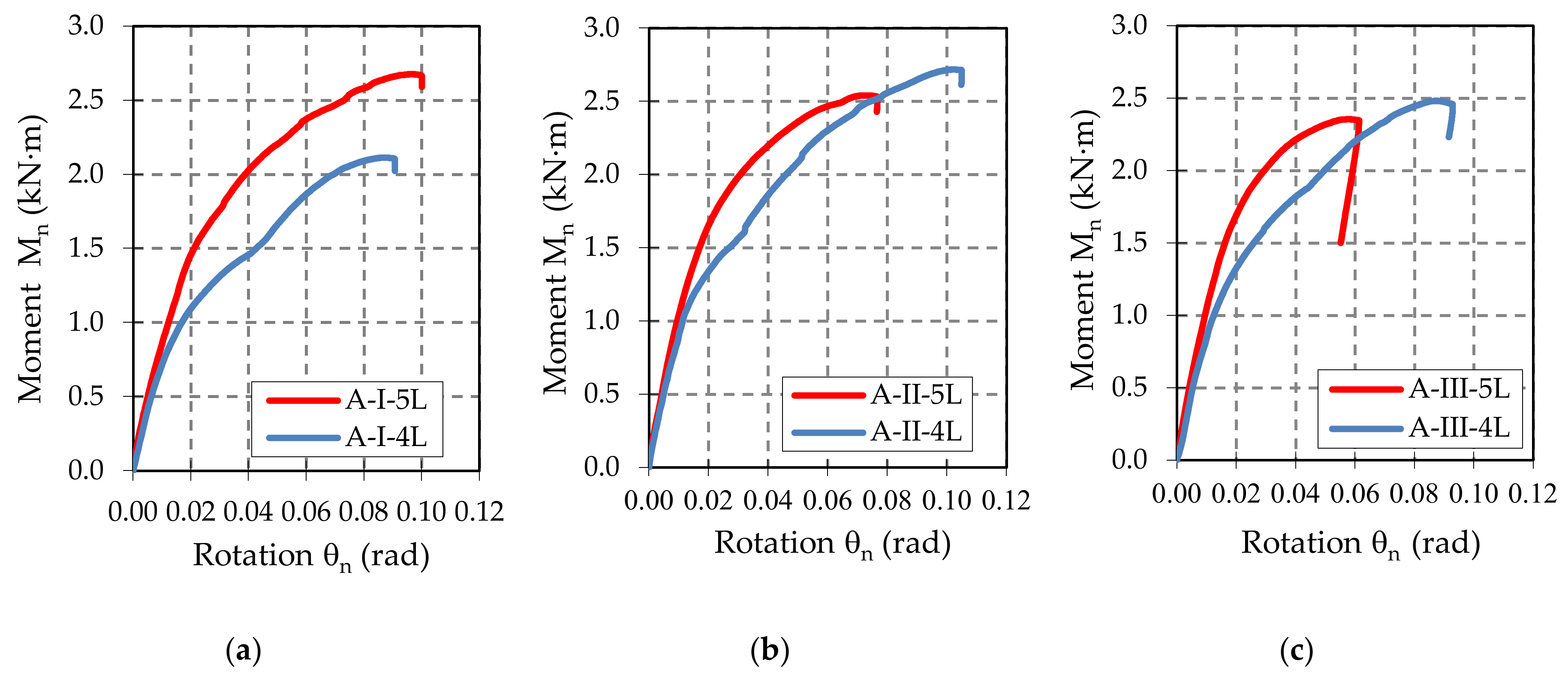
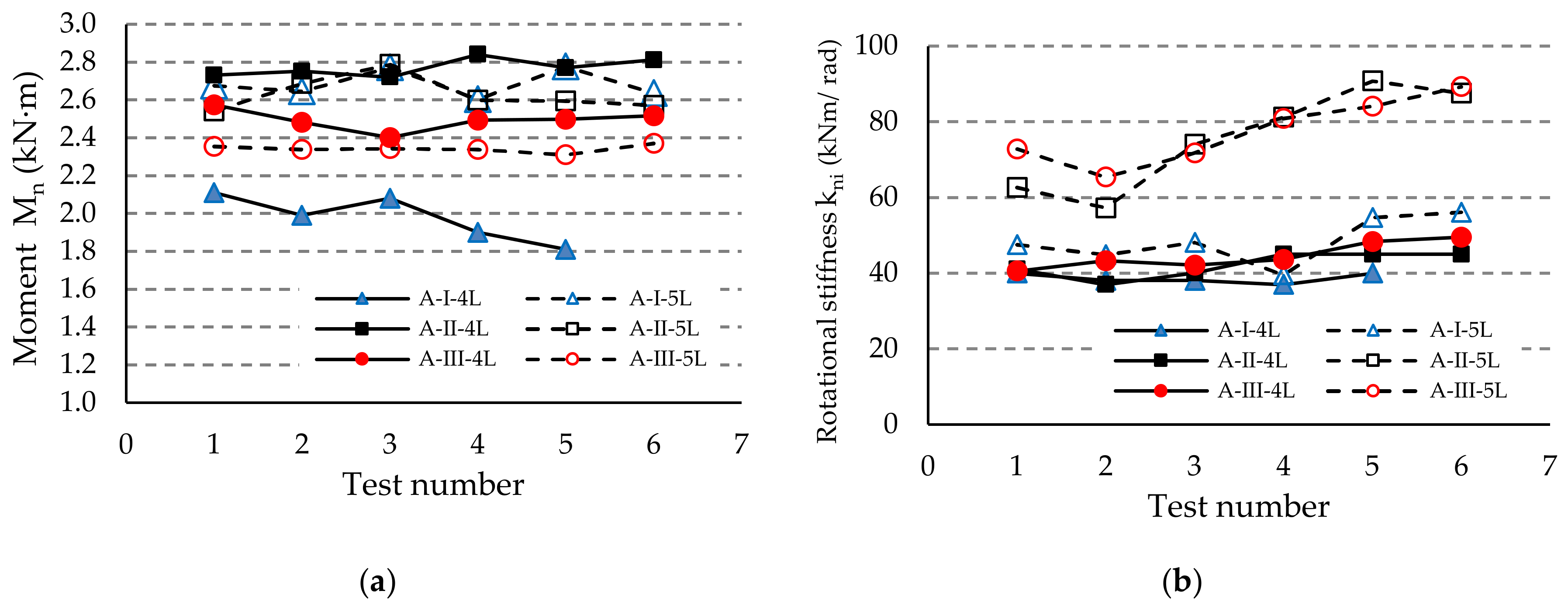
- For the assemblies containing the uprights of type I with a thickness of 1.50 mm, the five-tab connector leads to a higher value of the design moment MRd and higher rotational stiffness km than in the assemblies with four-tab connectors. This behavior was noticed for all three types of beams (A, B, C) with different heights of the beam being cross sectional (Table 6).
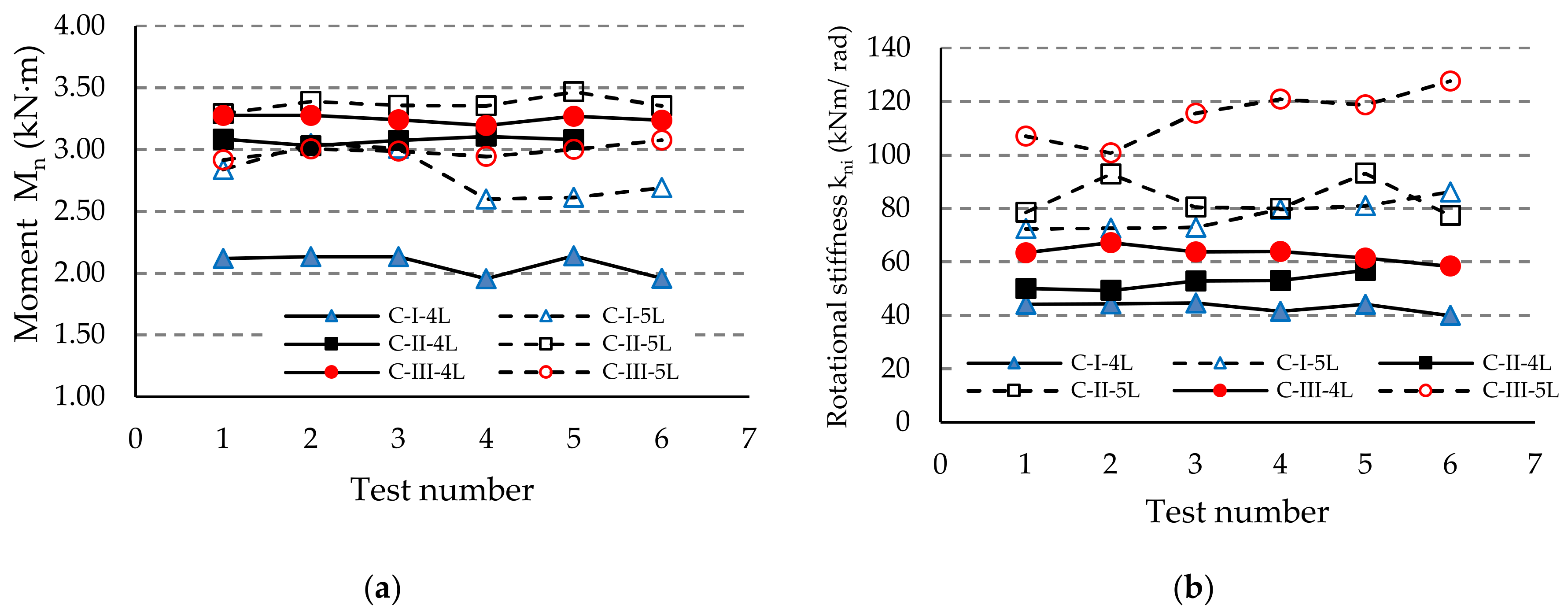
- When the upright thickness increases (upright III), a change in the failure modes was observed because the five-tab connector rotates less than the four-tab connector (Figure 17 and Figure 18). The rotational stiffness km of the connection is higher for the assemblies with five-tab connectors than for the assemblies with four-tab connectors. On the contrary, the capable design moment MRd decreases for a five-tab connector, which is more visible in the bending tests applied to the assembly that contain the uprights of type III having a thickness of 2.00 mm (Table 6).
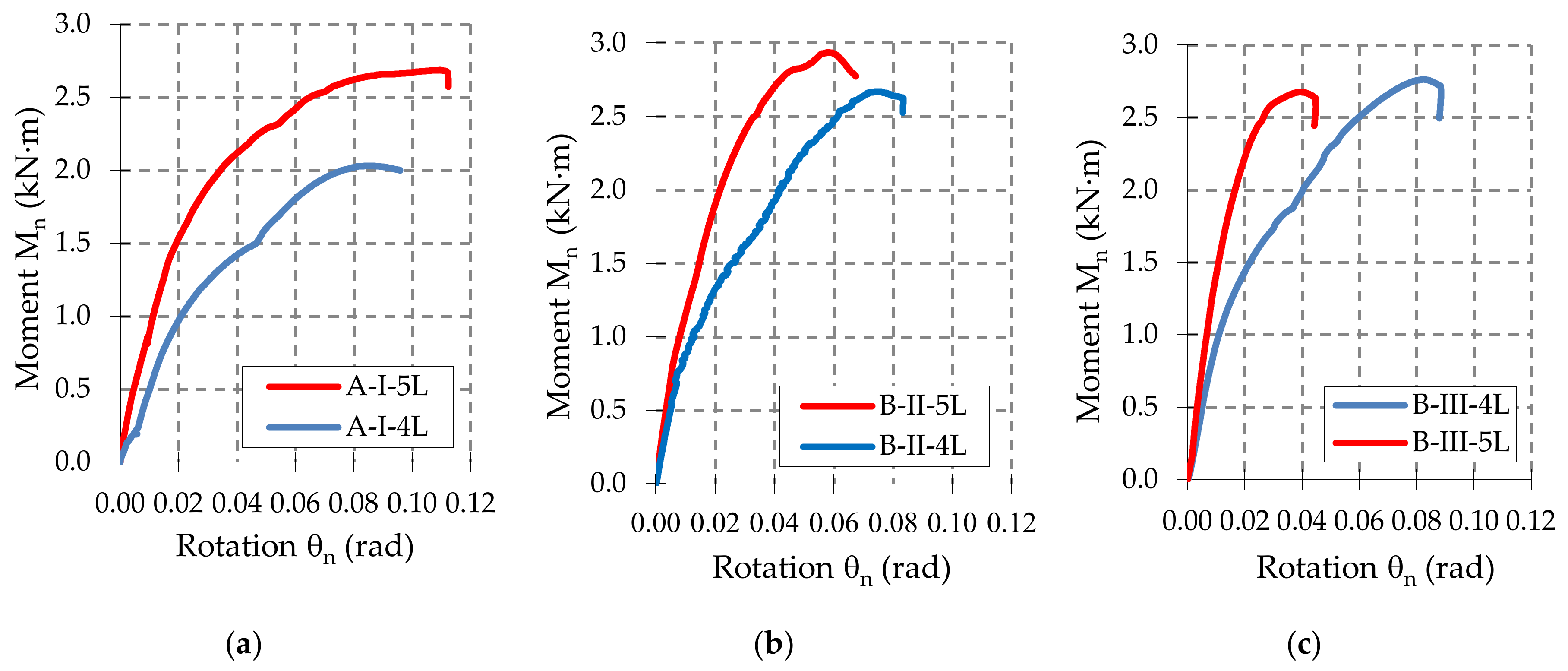
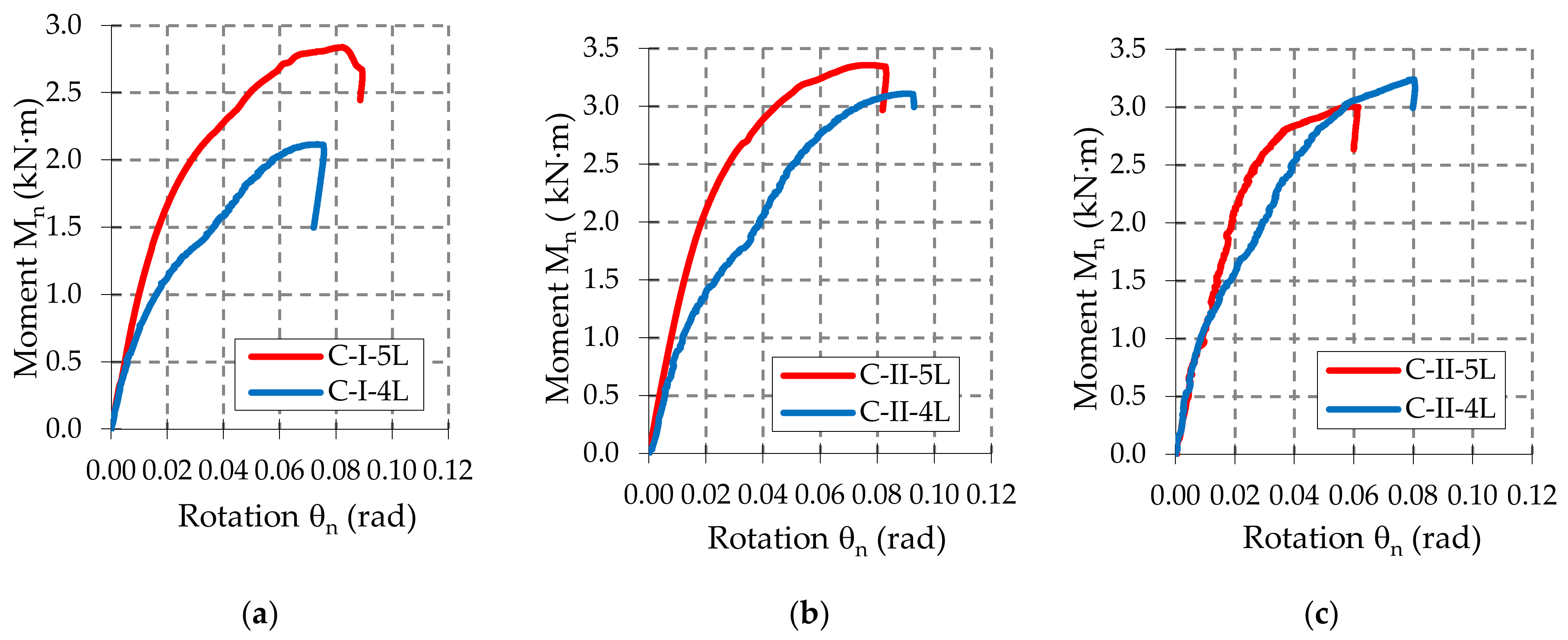
- As the upright thickness increases, the portion of the moment-rotation curves corresponding to the plastic behavior for the assemblies containing four-tab connectors is greater than the curve portion in plastic corresponding to the assemblies containing the five-tab connectors (Figure 9, Figure 10 and Figure 11). The mechanical behavior of the material is characteristic of elastic-plastic metallic materials [10,24].
- For the assemblies containing B or C beams with a section height of 100 mm or 110 mm, respectively, and containing a five-tab connector, the design moment MRd and rotational stiffness km of the joints increase due to the upright sections having a thickness of 1.5 mm or 1.75 mm. For the assemblies containing the upright sections with a thickness of 2.00 mm, the rotational stiffness km still increases, but design moment MRd of the connection decreases. In the assemblies with a 5-tab connector, the capable design moment MRd corresponding to the upright III having the thickness of 2.00 mm, is lower than the capable moment MRd corresponding to the upright I with a thickness of 1.75 mm upright regions in case of all types of beams.
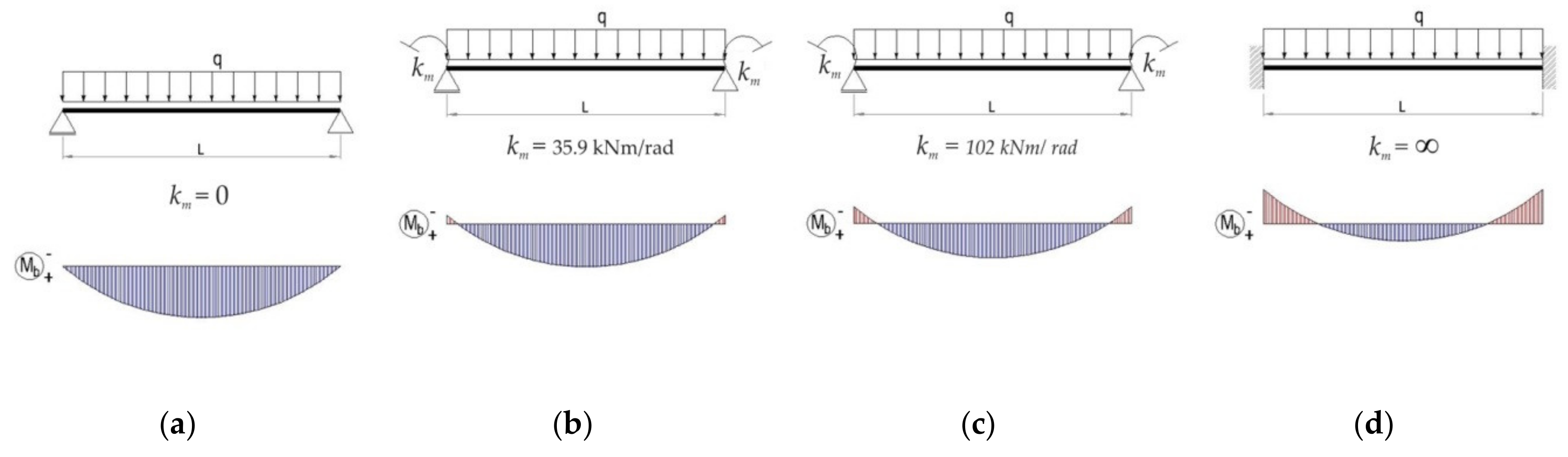
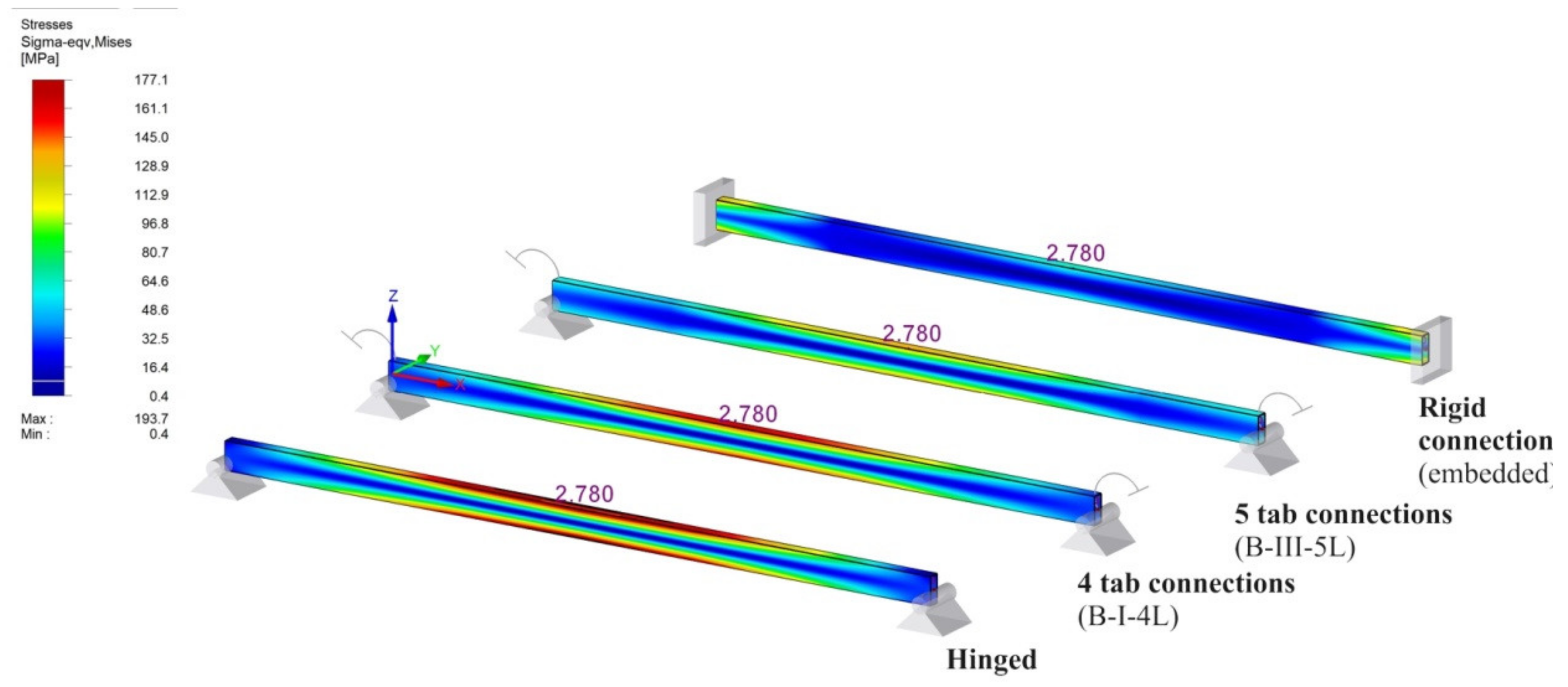
- (i)
- beam B shown in Figure 20a, for which the rotational stiffness of the connections is equal to 0 that corresponds to hinged beam ends,
- (ii)
- beam B shown in Figure 20b, for which the rotational stiffness km of both end connections is equal to 35.9 kNm/rad corresponding to the semi-rigid connection,
- (iii)
- beam B shown in Figure 20c, for which the rotational stiffness km of both end connections is equal to 102 kNm/rad corresponding to the semi-rigid connection,
- (iv)
- beam B shown in Figure 20d, for which the rotational stiffness km of the connections is infinite and corresponds to the rigid connections (fixed beam ends).
5. Conclusions
Author Contributions
Funding
Acknowledgments
Conflicts of Interest
Appendix A


References
- Shariati, M.; Tahir, M.M.; Wee, T.C.; Shah, S.N.R.; Jalali, A.; Abdullahi, M.M.; Khorami, M. Experimental investigations on monotonic and cyclic behavior of steel pallet rack connections. Eng. Fail. Anal. 2018, 85, 149–166. [Google Scholar] [CrossRef]
- Zhao, X.Z.; Wang, T.; Chen, Y.Y.; Sivakumaran, K.S. Flexural behavior of steel storage rack beam-to-upright connections. J. Constr. Steel Res. 2014, 99, 161–175. [Google Scholar] [CrossRef]
- Dai, L.S.; Zhao, X.Z.; Rasmussen, K.J.R. Flexural behaviour of steel storage rack beam-to-upright bolted connections. Thin-Walled Struct. 2018, 124, 202–217. [Google Scholar] [CrossRef]
- Elza, M.M.; Fonseca, L.S.; Pedro, A.S. Numerical model to predict the effect of wood density in wood–steel–wood connections with and without passive protection under fire. J. Fire Sci. 2020, 38, 122–135. [Google Scholar] [CrossRef]
- Gusella, F.; Lavacchini, G.; Orlando, M. Monotonic and cyclic tests on beam-column joints of industrial pallet racks. J. Constr. Steel Res. 2018, 140, 92–107. [Google Scholar] [CrossRef]
- Dai, L.S.; Zhao, X.Z.; Rasmussen, K.J.R. Cyclic performance of steel storage rack beam-to-upright bolted connections. J. Constr. Steel Res. 2018, 148, 28–48. [Google Scholar] [CrossRef]
- Yin, L.F.; Tang, G.; Zhang, M.; Wang, B.J.; Feng, B. Monotonic and cyclic response of speed-lock connections with bolts in storage racks. Eng. Struct. 2016, 116, 40–55. [Google Scholar] [CrossRef]
- Eurocode 3: Design of steel structures: Part 1-3: General rules. Supplementary rules for cold-formed members and sheeting. In Design of Joints; EN 1993-1-3; European Committe for Standardization: Brussels, Belgium, 2006; p. 12.
- Standard, B. Steel Static Storage Systems—Adjustable Pallet Racking Systems—Principles for Structural Design; EN 15512; European Committe for Standardization: Brussels, Belgium, 2009. [Google Scholar]
- Mohan, V.; Prabha, P.; Rajasankar, J.; Iyer, N.R.; Raviswaran, N.; Nagendiran, V.; Kamalakannan, S.S. Cold-formed steel pallet rack connection: An experimental study. Int. J. Adv. Struct. Eng. (IJASE) 2015, 7, 55–68. [Google Scholar] [CrossRef] [Green Version]
- Zhao, X.Z.; Dai, L.S.; Wang, T.; Sivakumaran, K.S.; Chen, Y.Y. A theoretical model for the rotational stiffness of storage rack beam-to-upright connections. J. Constr. Steel Res. 2017, 133, 269–281. [Google Scholar] [CrossRef]
- Gusella, F.; Orlando, M.; Thiele, K. Evaluation of rack connection mechanical properties by means of the Component Method. J. Constr. Steel Res. 2018, 149, 207–224. [Google Scholar] [CrossRef]
- Gusella, F.; Arwade, S.R.; Orlando, M.; Peterman, K.D. Influence of mechanical and geometric uncertainty on rack connection structural response. J. Constr. Steel Res. 2019, 153, 343–355. [Google Scholar] [CrossRef]
- Degtyareva, N.V.; Degtyarev, V.V. Experimental investigation of cold-formed steel channels with slotted webs in shear. Thin-Walled Struct. 2016, 102, 30–42. [Google Scholar] [CrossRef]
- Degtyareva, N.V. Review of Experimental Studies of Cold-Formed Steel Channels with Slotted Webs under Bending. Procedia Eng. 2017, 206, 875–880. [Google Scholar] [CrossRef]
- Degtyarev, V.V.; Degtyareva, N.V. Finite element modeling of cold-formed steel channels with solid and slotted webs in shear. Thin-Walled Struct. 2016, 103, 183–198. [Google Scholar] [CrossRef]
- Garrido, C. MECALUX-Warehouse Storage Solutions. Fire Protection Measures for Metal Racks and Warehouses. Available online: https://www.mecalux.com/logistics-items/fire-protection-measures-for-metal-racks-and-warehouses (accessed on 23 June 2020).
- Laim, L.; Rodrigues, J.P.C. Fire design methodologies for cold-formed steel beams made with open and closed cross-sections. Eng. Struct. 2018, 171, 759–778. [Google Scholar] [CrossRef]
- Craveiro, H.; Rodrigues, J.P.C.; Laim, L. Cold-formed steel columns at both ambient and fire conditions. J. Struct. Fire Eng. 2018, 9, 189–202. [Google Scholar] [CrossRef]
- RMI. Specification for the design, testing and utilization of industrial steel storage racks. In Pallet Beam-to-Column Connection Tests; Rack Manufactures Institute: Charlotte, NC, USA, 2008; p. 4. [Google Scholar]
- Dumbrava, F. Research Report: Experimental Research on Stress States and Deformations of Elements (Columns, Beams, etc.) in the Construction of Thin-Walled Metal Structures; Transilvania University of Brasov: Brașov, Romania, 2020. [Google Scholar]
- European Committe for Standardization. Metallic materials. Tensile Testing. Part 1: Method of Test at Room Temperature; BS EN ISO 6892-1; European Committe for Standardization: Brussels, Belgium, 2009. [Google Scholar]
- European Committe for Standardization. Continuously Hot-Dip Coated Steel Flat Products—Technical Delivery Conditions; BS EN 10346; European Committe for Standardization: Brussels, Belgium, 2009. [Google Scholar]
- Cerbu, C.; Teodorescu-Draghicescu, H. Aspects on modeling the mechanical behavior of aluminum alloys with different heat treatments. J. Comput. Appl. Mech. 2017, 12, 13. [Google Scholar] [CrossRef]


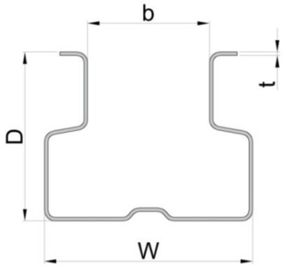
| Type of the Upright | Code of the Upright | D * | W * | B * | T * |
|---|---|---|---|---|---|
| (mm) | (mm) | (mm) | (mm) | ||
| 90 × 1.50 | I | 70 | 90 | 50 | 1.50 |
| 90 × 1.75 | II | 1.75 | |||
| 90 × 2.00 | III | 2.00 |
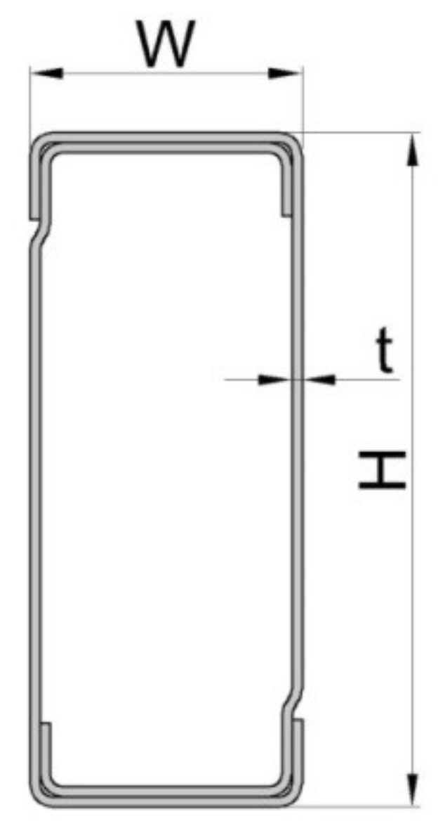
| Beam Type | Beam Code | H * | W * | t * |
|---|---|---|---|---|
| (mm) | (mm) | (mm) | ||
| BOX 90 | A | 90 | 40 | 1.50 |
| BOX 100 | B | 100 | 40 | 1.50 |
| BOX 110 | C | 110 | 40 | 1.50 |
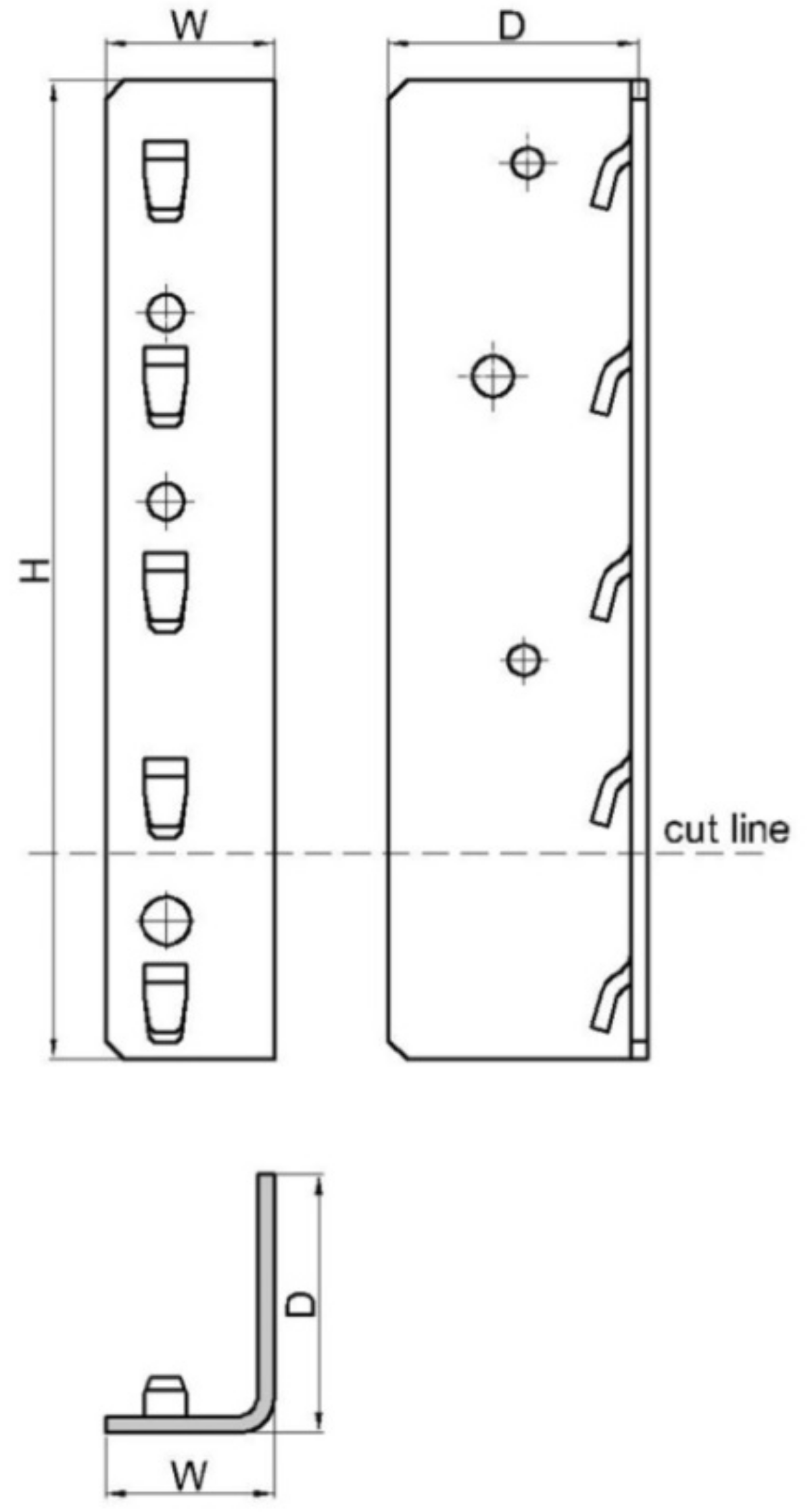
| Connector Type | Connector Code | No. of Tabs | H * | D * | W * | Thickness |
|---|---|---|---|---|---|---|
| (mm) | (mm) | (mm) | (mm) | |||
| 5-tab connector | 5L | 5 | 238 | 63 | 41 | 4.0 |
| 4-tab connector | 4L | 4 | 190 | 63 | 41 | 4.0 |
| Assembly Identification Code | Upright | Beam | Connector Type | Number of Tests for Assembly |
|---|---|---|---|---|
| A-I-4L | 90 × 1.50 | A (BOX 90) | 4L | 5 |
| A-I-5L | 5L | 6 | ||
| A-II-4L | 90 × 1.75 | 4L | 6 | |
| A-II-5L | 5L | 6 | ||
| A-III-4L | 90 × 2.00 | 4L | 6 | |
| A-III-5L | 5L | 6 | ||
| B-I-4L | 90 × 1.50 | B (BOX 100) | 4L | 5 |
| B-I-5L | 5L | 6 | ||
| B-II-4L | 90 × 1.75 | 4L | 6 | |
| B-II-5L | 5L | 6 | ||
| B-III-4L | 90 × 2.00 | 4L | 3 | |
| B-III-5L | 5L | 5 | ||
| C-I-4L | 90 × 1.50 | C (BOX 110) | 4L | 6 |
| C-I-5L | 5L | 6 | ||
| C-II-4L | 90 × 1.75 | 4L | 6 | |
| C-II-5L | 5L | 6 | ||
| C-III-4L | 90 × 2.00 | 4L | 5 | |
| C-III-5L | 5L | 6 |
| Component Corresponding to the Tensile Specimen | Measured Thickness | Yield Stress Rp,02 ft * | Ultimate Stress fu * | Strain * |
|---|---|---|---|---|
| (mm) | (MPa) | (MPa) | (%) | |
| Upright I (90 × 1.50) | 1.48 | 447.9 | 528.9 | 19.2 |
| Upright II (90 × 1.75) | 1.80 | 496.2 | 536.2 | 15.3 |
| Upright III (90 × 2.00) | 2.09 | 535.1 | 590.2 | 18.5 |
| Beam A (box 90) | 1.25 | 360.6 | 459.5 | 38.8 |
| Beam B (box 100) | 1.23 | 379.8 | 429.5 | 29.7 |
| Beam C (box 110) | 1.27 | 344.2 | 411.6 | 38.1 |
| 4-tab connector Box 90 | 4.04 | 409.9 | 469.8 | 25.6 |
| 5-tab connector Box 90 | 4.04 | 409. | 469.8 | 25.6 |
| 4-tab connector Box 100 | 4.07 | 395.3 | 464 | 32.6 |
| 5-tab connector Box 100 | 4.07 | 395.3 | 464 | 32.6 |
| 4-tab connector Box 110 | 4.05 | 444.7 | 503.5 | 24.5 |
| 5-tab connector Box 110 | 4.05 | 444.7 | 503.5 | 24.5 |
| Assembly code | Design Moment | Rotational Stiffness | Assembly code | Design Moment | Rotational Stiffness | Assembly code | Design Moment | Rotational Stiffness | ||||||||||||
|---|---|---|---|---|---|---|---|---|---|---|---|---|---|---|---|---|---|---|---|---|
| Mni | MRd | Stdev | kni | km | Stdev | Mni | MRd | Stdev | kni | km | Stdev | Mni | MRd | Stdev | kni | km | Stdev | |||
| (kNm) | (kNm) | (kNm) | (kNm/ rad) | (kNm/ rad) | (kNm/ rad) | (kNm) | (kNm) | (kNm) | (kNm / rad) | (kNm / rad) | (kNm / rad) | (kNm) | (kNm) | (kNm) | (kNm / rad) | (kNm / rad) | (kNm / rad) | |||
| A-I-4L | 2.11 | 1.54 | 0.12 | 40 | 39.0 | 1.34 | B-I-4L | 2.03 | 1.84 | 0.02 | 34 | 35.9 | 1.38 | C-I-4L | 2.12 | 1.70 | 0.08 | 44 | 43.7 | 1.26 |
| 1.99 | 38 | 2.06 | 36 | 2.13 | 44 | |||||||||||||||
| 2.08 | 38 | 2.08 | 35 | 2.13 | 45 | |||||||||||||||
| 1.90 | 37 | 2.07 | 38 | 1.95 | 41 | |||||||||||||||
| 1.81 | 40 | 2.07 | 37 | 2.14 | 44 | |||||||||||||||
| 1.96 | 40 | |||||||||||||||||||
| A-I-5L | 2.68 | 2.3 | 0.07 | 47 | 48.0 | 6.18 | B-I-5L | 2.69 | 2.24 | 0.12 | 55 | 57.8 | 7.29 | C-I-5L | 2.84 | 2.15 | 0.20 | 72 | 77.4 | 5.71 |
| 2.65 | 45 | 2.75 | 59 | 3.05 | 73 | |||||||||||||||
| 2.77 | 48 | 2.62 | 46 | 3.01 | 73 | |||||||||||||||
| 2.60 | 40 | 2.58 | 61 | 2.60 | 80 | |||||||||||||||
| 2.78 | 55 | 2.76 | 58 | 2.61 | 81 | |||||||||||||||
| 2.64 | 56 | 2.92 | 68 | 2.69 | 86 | |||||||||||||||
| A-II-4L | 2.73 | 2.43 | 0.05 | 41 | 42.0 | 3.37 | B-II-4L | 3.04 | 2.03 | 0.18 | 56.1 | 56.0 | 1.65 | C-II-4L | 3.08 | 2.74 | 0.03 | 50.1 | 52.4 | 2.97 |
| 2.75 | 37 | 2.67 | 54.3 | 3.03 | 49.3 | |||||||||||||||
| 2.72 | 40 | 2.87 | 57.6 | 3.07 | 52.8 | |||||||||||||||
| 2.84 | 45 | 3.11 | 53.1 | |||||||||||||||||
| 2.77 | 45 | 3.08 | 56.8 | |||||||||||||||||
| 2.81 | 45 | |||||||||||||||||||
| A-II-5L | 2.54 | 2.21 | 0.09 | 63 | 76.0 | 13.5 | B-II-5L | 2.66 | 2.36 | 0.10 | 65 | 86.1 | 15.7 | C-II-5L | 3.29 | 2.95 | 0.06 | 79 | 83.7 | 7.25 |
| 2.69 | 57 | 2.78 | 77 | 3.39 | 93 | |||||||||||||||
| 2.79 | 74 | 2.75 | 76 | 3.36 | 81 | |||||||||||||||
| 2.60 | 81 | 2.85 | 100 | 3.35 | 80 | |||||||||||||||
| 2.59 | 91 | 2.87 | 105 | 3.47 | 93 | |||||||||||||||
| 2.57 | 88 | 2.94 | 94 | 3.35 | 77 | |||||||||||||||
| A-III-4L | 2.57 | 2.16 | 0.06 | 41 | 45.0 | 3.57 | B-III-4L | 2.76 | 2.43 | 0.03 | 50 | 51.2 | 2.97 | C-III-4L | 3.28 | 2.89 | 0.03 | 63 | 63.0 | 2.93 |
| 2.48 | 43 | 2.74 | 50 | 3.27 | 67 | |||||||||||||||
| 2.40 | 42 | 2.78 | 47 | 3.24 | 64 | |||||||||||||||
| 2.49 | 44 | 2.75 | 53 | 3.20 | 64 | |||||||||||||||
| 2.50 | 48 | 2.70 | 55 | 3.27 | 61 | |||||||||||||||
| 2.52 | 50 | 2.71 | 52 | 3.24 | 58 | |||||||||||||||
| A-III-5L | 2.36 | 2.09 | 0.02 | 73 | 77.0 | 8.90 | B-III-5L | 2.52 | 2.18 | 0.07 | 80 | 102 | 20.9 | C-III-5L | 2.92 | 2.61 | 0.06 | 107 | 115 | 9.76 |
| 2.34 | 65 | 2.49 | 86 | 3.01 | 101 | |||||||||||||||
| 2.34 | 72 | 2.55 | 98 | 2.99 | 116 | |||||||||||||||
| 2.34 | 81 | 2.55 | 114 | 2.94 | 121 | |||||||||||||||
| 2.31 | 84 | 2.68 | 131 | 3.00 | 119 | |||||||||||||||
| 2.37 | 89 | 3.08 | 128 | |||||||||||||||||
| Assembly Code | Rotational Stiffness km | Design Moment MRd | Moment at End Mend | Safety Coefficient c | Maximum Deflection vmax | Ratio vall ***/ vmax |
|---|---|---|---|---|---|---|
| (kN·m/rad) | (kN·m) | (kN·m) | (mm) | (%) | ||
| A-I-4L | 39.0 | 1.54 | 0.52 | 2.94 | 12.35 | 1.09 |
| A-I-5L | 48.0 | 2.30 | 0.60 | 3.82 | 11.74 | 1.15 |
| A-II-4L | 42.0 | 2.43 | 0.55 | 4.41 * | 12.14 | 1.11 |
| A-II-5L | 76.0 | 2.21 | 0.79 | 2.80 | 10.29 | 1.31 |
| A-III-4L | 45.0 | 2.16 | 0.58 | 3.75 | 11.94 | 1.13 |
| A-III-5L | 77.0 | 2.09 | 0.79 | 2.63 ** | 10.25 | 1.32 |
| B-I-4L | 35.9 | 1.84 | 0.41 | 4.47 | 10.31 | 1.31 |
| B-I-5L | 57.8 | 2.24 | 0.58 | 3.88 | 9.31 | 1.45 |
| B-II-4L | 56.0 | 2.03 | 0.57 | 3.59 | 9.38 | 1.44 |
| B-II-5L | 86.1 | 2.36 | 0.74 | 3.20 | 8.34 | 1.62 |
| B-III-4L | 51.2 | 2.43 | 0.53 | 4.57 * | 9.58 | 1.41 |
| B-III-5L | 102.0 | 2.18 | 0.81 | 2.70 ** | 7.91 | 1.71 |
| C-I-4L | 43.7 | 1.70 | 0.40 | 4.22 | 8.27 | 1.63 |
| C-I-5L | 77.4 | 2.15 | 0.60 | 3.56 | 7.30 | 1.85 |
| C-II-4L | 52.4 | 2.74 | 0.46 | 5.94 * | 7.99 | 1.69 |
| C-II-5L | 83.7 | 2.95 | 0.63 | 4.65 | 7.15 | 1.89 |
| C-III-4L | 63.0 | 2.89 | 0.53 | 5.50 | 7.68 | 1.76 |
| C-III-5L | 115.0 | 2.61 | 0.76 | 3.42 ** | 6.52 | 2.07 |
© 2020 by the authors. Licensee MDPI, Basel, Switzerland. This article is an open access article distributed under the terms and conditions of the Creative Commons Attribution (CC BY) license (http://creativecommons.org/licenses/by/4.0/).
Share and Cite
Dumbrava, F.; Cerbu, C. Experimental Study on the Stiffness of Steel Beam-to-Upright Connections for Storage Racking Systems. Materials 2020, 13, 2949. https://doi.org/10.3390/ma13132949
Dumbrava F, Cerbu C. Experimental Study on the Stiffness of Steel Beam-to-Upright Connections for Storage Racking Systems. Materials. 2020; 13(13):2949. https://doi.org/10.3390/ma13132949
Chicago/Turabian StyleDumbrava, Florin, and Camelia Cerbu. 2020. "Experimental Study on the Stiffness of Steel Beam-to-Upright Connections for Storage Racking Systems" Materials 13, no. 13: 2949. https://doi.org/10.3390/ma13132949
APA StyleDumbrava, F., & Cerbu, C. (2020). Experimental Study on the Stiffness of Steel Beam-to-Upright Connections for Storage Racking Systems. Materials, 13(13), 2949. https://doi.org/10.3390/ma13132949