Abstract
The tandem pn-type dye-sensitized solar cells (pn-DSCs) have received much attention in the field of photovoltaic technologies because of their great potential to overcome the Shockley-Queisser efficiency limitation that applies to single junction photovoltaic devices. However, factors governing the short-circuit current densities (Jsc) of pn-DSC remain unclear. It is typically believed that Jsc of the pn-DSC is limited to the highest one that the two independent photoelectrodes can achieve. In this paper, however, we found that the available Jsc of pn-DSC is always determined by the larger Jsc that the photoanode can achieve but not by the smaller one in the photocathode. Such experimental findings were verified by a simplified series circuit model, which shows that a breakdown will occur on the photocathode when the photocurrent goes considerably beyond its threshold voltage, thus leading to an abrupt increase in Jsc of the circuit. The simulation results also suggest that a higher photoconversion efficiency of the pn-DSCs can be only achieved when an almost equivalent photocurrent is achieved for the two photoelectrodes.
1. Introduction
Dye-sensitized solar cells (DSCs) have attracted a great deal of attention during the last three decades due to their projected low cost and comparably facile assembly. A typical DSC is constructed by sandwiching a photocathode which is usually a dye-sensitized TiO2 and a counter electrode. Although lots of research and development of these systems have been carried out since the initial breakthrough in 1991, the same concept is still used [1]. To make DSCs more competitive in future utilization, the next big step is to improve efficiency up to 15–20% [2]. Therefore, an apparent and simple way to improve the efficiency of the DSC is to construct a tandem structure DSCs [3]. The theoretical upper limit for a typical dye-sensitized solar cell is around 30%. Tandem solar cells (t-SCs), compared with single junction solar cells, have higher theoretical efficiency limitations [4]. For two junction solar cells, the theoretical efficiency limitation is around 42% [5,6]. Recently, the most efficient solar cells are operated in tandem structure. The most efficient two junction devices have reached a PCE (Power Conversion Efficiency) over 30% [7,8]. However, compared with single junction solar cells, the fabrication of t-SCs is always more complicated, which may significantly limit their utilization. However, Pn-DSCs which combine a photoanode and a photocathode into a single device represent an exceptional case [9,10]. As two junction solar cells, pn-DSCs have a simple preparation process which is almost the same as the traditional single junction dye-sensitized solar cells (n-DSCs or p-DSCs) [11,12,13,14]. These advantages make them more competitive in future applications.
The first pn-DSC with an efficiency of 0.39% was reported in 2000 [6]. Since then, an increasing number of research articles have been published in this area [11,15,16,17,18,19]. Suzuki and co-workers reported a pn-DSC with a better-quality mesoporous NiO photocathode achieving a PCE of 0.66% with a Jsc of 3.62 mA/cm2 [20]. In 2009, Elizabeth A. Gibson et al. reported a pn-DSC with a PCE of 0.55% [21]. In 2010, A. Nattestad et al. reported a well optimized pn-DSCs with a record PCE of 1.91% [9]. In 2012, an Se based photocathode for pn-DSC was developed with a PCE of 0.98% [22]. Recently, J.H.Kim et al. improve efficiency through the blocking layer at the photocathode interface to 1.91% [23].
Current mismatch between the photocathode and the photoanode is one of the most critical issues limiting the performance of pn-DSCs, and thus may lead to poor FF (Fill Factor) or PCE of the pn-DSCs lower than that of the corresponding n-DSCs [19,24,25]. In this paper, we discuss the problems of current mismatch and summarize how to get a good current match in pn-DSCs. The Jsc of the pn-DSCs is considerably governed by the weakest photoelectrode. In our study, we found that the Jsc of the pn-DSCs is always determined by the photoanode, no matter which photoelectrode is weaker. We adopted a simple series circuit equation to model the J-V curve of pn-DSCs which corresponded n-DSC and p-DSC. Furthermore, this work studied the Pn-DSCs with the same photocathode and a different performance photoanode. The calculation results show good agreement with the experiment.
2. Experimental
The structures of pn-DSC, n-DSC and p-DSC were illustrated in Figure 1. Pn-DSC was fabricated by sandwiching a typical photoanode with a polymer based photocathode. The n-DSC was fabricated by sandwiching a typical photoanode with a Pt counter electrode. A photoanode with a different photocurrent was prepared by changing the TiO2 thickness. The p-DSC was fabricated by sandwiching a polymer based photocathode with a Pt counter electrode. The typical photoanode was constructed as described elsewhere [26]. A transparent, mesoporous TiO2 film was prepared by sintering TiO2 paste-coated FTO (Fluorine-doped SnO2 transparent conductive glass) at 510 °C for 30 min. The mesoporous TiO2 films were then cooled to 80 °C and immersed in an ethanol solution of a ruthenium-complex (N719 dye) overnight, followed by rinsing in ethanol and drying. The polymer based photocathodes were fabricated as follows: mesoporous NiO film was fabricated on FTO by spin coating, followed by sintering at 510 °C for 30 min under atmospheric. Spin coating paste was produced by mixing a slurry of 10 g of NiO nanopowder (Sigma Aldrich, Saint Louis, MO, USA) in ethanol with 30 g of 10 wt% ethanolic ethyl cellulose (Sigma Aldrich, Saint Louis, MO, USA) solution, 35 g terpineol, and 75 g ethanol. Then spin-cast a blend chlorobenzene solution containing PCPDTBT (Poly[2,1,3-benzothiadiazole-4,7-diyl[4,4-bis(2-ethylhexyl)-4H-cyclopenta[2,1-b:3,4-b’]dithiophene-2,6-diyl]]) and PCBM ([6,6]-phenyl-C61-butyric acid methyl ester) (15 mg/mL, 35 mg/mL) on the mesoporous NiO film, followed by removing the PCBM by simply soaking this hybrid film in 3-methoxypropionitrile (MePN). Electrolytes used for all n-DSCs, p-DSCs and pn-DSCs were similar (0.6 M N-methyl-N-butylimidazolium iodide, 0.45 M N-Methyl benzimidazole, 0.1 M LiI and 0.1 M I2 in 3-Methoxypropionitrile).
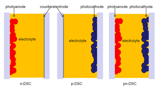
Figure 1.
Structure of n-DSC, p-DSC and pn-DSC.
The photovoltaic performances of the DSCs were measured using a Keithley 2420 3A source meter (Tektronix, Beaverton, OR, USA) controlled by Labview software under AM 1.5 solar simulator of 100 mW cm−2 (solar AAA simulator, oriel USA, calibrated with a standard crystalline silicon solar). The active area of the samples was 0.25 cm2 (with a black mask). Absorption spectra were obtained from a UV-vis spectrophotometer (U-3900H, Hitachi, Tokyo, Japan).
3. Results and Discussion
Photocurrent matching is an essential prerequisite for the realization of highly efficient pn-DSCs. However, the reported photocurrent of photocathode ever reported is still far behind the well optimized photoanode, and thus can lead to the significant photocurrent mismatch in pn-DSCs.
Equivalence circuit analysis has been widely used in DSCs to study the electric mechanism [27,28]. For pn-DSCs, an equivalence circuit can be simplified as a series connection of a n-DSC and a p-DSC (as shown in Figure 2) [29]. Here we adopted a simplified series circuit model that has been used in series connection DSCs to calculate the J-V characters of pn-DSCs which corresponded n-DSC and p-DSC [30,31,32]. In this model, we used J-V characters of the corresponding n-DSC and p-DSC to replace the actual J-V characters of the photoelectrodes.
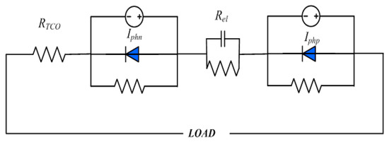
Figure 2.
The simplified equivalence circuit of the pn-DSC.
Because of the series connection of two photoelectrodes in pn-DSCs, the photoanode and the photocathode work in the same current, whereas the voltage is the sum of two photoelectrodes as shown in Figure 3. The voltage and current of the pn-DSCs can be expressed as the following Equations (1) and (2):
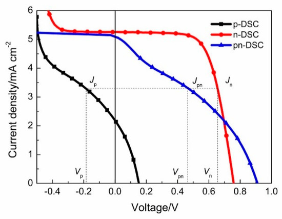
Figure 3.
The simulated J-V curve of pn-DSCs from the corresponding n-DSC and p-DSC.
The reported P-DSCs in the literature that are based on the I−/I3− electrode and NiO exhibited a very low Voc typically below 0.2 V and a FF between 30–40% [33]. Figure 4 shows the typical J-V characteristics of a p-DSC from our experimental samples. Details of J-V characteristics are shown in Table 1, the p-DSC exhibits a PCE of 0.12%, a Voc of 0.15 V, a Jsc of 2.15 mA cm−2 and a FF of 33.5%. Under negative bias, photocurrent density increases with the applied negative bias. When the negative bias exceeds 0.4 V (the threshold voltage of p-DSCs), there is a breakdown of p-DSCs, which exhibits a sharp increase in photocurrent density.
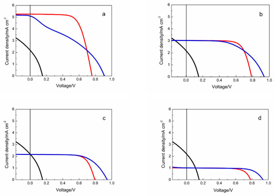
Figure 4.
J-V curves of the calculated pn-DSC (blue line) as well as the corresponding n-DSC (red line) and p-DSC (black line). (a) Pn-DSC with a high performance photoanode and the photocathode; (b) Jsc of n-DSC in the range from Jsc to the threshold photocurrent density of the p-DSC; (c) Photocurrent of the two photocathode are well matched; (d) Jsc of the n-DSC lower than that of p-DSC.

Table 1.
Photovoltaic parameters of the calculated pn-DSCs as well as p-DSCs and n-DSCs.
Figure 4 shows the simulated J-V characters of pn-DSCs with the photocathode mentioned above and a changed photoanode (the different performance of photoanode are achieved by adjusting the TiO2 thickness): (a) Pn-DSC with a high performance photoanode and the photocathode. The corresponding Jsc of n-DSC is far larger than that of p-DSC, even larger than the threshold current density of p-DSC; (b) Jsc of n-DSC in the range from Jsc to the threshold photocurrent density of the p-DSC. (c) Photocurrent of the two photocathode are well matched; (d) Jsc of the n-DSC lower than that of p-DSC. All J-V curves of the n-DSCs and the p-DSC are achieved from our experiments.
Pn-DSCs and DSCs were illuminated through the photoanode side and the PSCs (Polymer Solar cells) through the photocathode side.
Figure 4a shows the J-V curve under the first condition. The corresponding n-DSC exhibit a PCE of 2.68% with a Voc of 0.76 V, Jsc of 5.26 mA cm−2, which is larger than the threshold current density of p-DSC, and a FF of 67.2% (Photovoltaic parameters of pn-DSCs, as well as p-DSCs and n-DSCs, are shown in Table 1). The J-V curve of the pn-DSC shows an S slope character with a low FF of 35.2%. The threshold voltage of p-DSC with this polymer based photocathode is between 0.4–0.5 V, which is much lower than the Voc of a typical n-DSC. Under the open circuit condition, the photocathode works under positive bias to get a constant current and thus leads to the Jsc of pn-DSCs which is similar with n-DSC. This is quite different from the natural consideration, and the photocurrent of pn-DSC is limited by the smaller one of the two photoelectrodes. Even though the open circuit voltage of the pn-DSC is a summation of the corresponding n-DSC and p-DSC, the voltage of the maximum power point (Vmax) has only a little increase (Table 1). In this condition, PCE of pn-DSCs (1.64%) is far behind the n-DSCs (2.68%). The previous pn-DSC did not achieve current matching, the fill factor is very low, and it is in the first state of our calculation [6,21].
Under the second condition, the Jsc of the corresponding n-DSC decreased to 3.04 mA cm−2 which is in the range from Jsc to the threshold photocurrent density of the p-DSC, as shown in Figure 4b. A normal J-V curve was obtained. The FF of pn-DSC increased to 54.5% as compared to the first condition. However, the PCE of pn-DSCs is still smaller than that of n-DSCs. The Jsc and the Vmav of the pn-DSCs are almost the same as that of n-DSCs.
Figure 4c shows the J-V curve of pn-DSC when the Jsc of the two single cells are well matched. The Jsc of the pn-DSCs are the same as the p-DSC and n-DSC. The FF of the pn-DSC reaches 64.0%, while still being lower than that of the n-DSC (72.3%) which is hampered by the low FF of the p-DSCs. Under this condition, both the PCE and the Vmax slightly increase as compared with the corresponding n-DSCs (Table 1). Nattestad et al. obtained a fill factor of 74% by adjusting the current matching between the photocathode and the photoanode, resulting in a photoelectric conversion efficiency of 1.91% [9]. This is consistent with our simulation calculations.
J-V characters of pn-DSCs with the Jsc of the corresponding n-DSC are lower than that of the p-DSC as shown in Figure 4d. The n-DSC used here shows a PCE of 0.57% with a Voc of 0.78 V and Jsc of 1.01 mA cm−2. The resulting pn-DSC exhibits a PCE of 0.67%, which is a considerable enhancement compared to the corresponding n-DSC. Furthermore, the Vmax shows an apparent increase from 0.64 V to 0.73 V. The FF of the pn-DSC is closer than the n-DSC, which indicates that a higher Jsc of the photocathode could result in a better FF. But the PCE of pn-DSC under this condition is lower than that of photocurrent matching.
Pn-DSCs and DSCs were illuminated through the photoanode side and the PSCs through the photocathode side.
Figure 5a shows the experimental result of the pn-DSCs with the same photocathode and the changed photoanode. Sensitizers of the two photoelectrodes exhibited good complementary absorption, and thus the influence from absorption of the photoanode to the photocathode is small. The J-V characters of the corresponding n-DSCs and p-DSC with the same photoelectrode are shown in Figure 5b (pn-DSC and n-DSC are illuminated from the photoanode side and the p-DSC are illuminated from the photocathode side). The photovoltaic parameters of pn-DSCs, p-DSCs and n-DSCs are shown in Table 2. The results from our experiment show a good agreement with the calculated values. The Voc of the pn-DSCs is the sum of the n-DSC and the p-DSC. Jsc of the pn-DSC are determined by the n-DSC, and the FF of pn-DSC increases when the Jsc of the n-DSC decrease. It is hard to determine the actual J-V character of the photocathode in pn-DSC. From the FF of the pn-DSC as compared to the calculation result, the pn-DSC with a FF of 65.3% (green line) could be considered close to a good current match, and the PCE of 1.33% is slightly larger than the 1.31% of the corresponding n-DSCs, also meeting the calculation result.
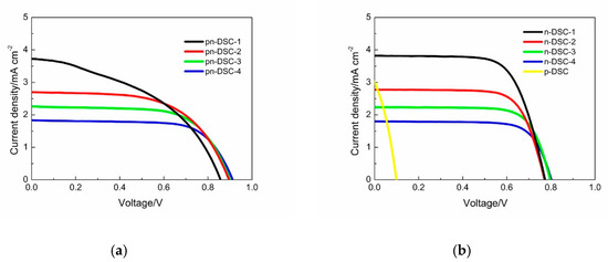
Figure 5.
(a) J-V curve of the pn-DSC with different photoanode; (b) J-V curve of the corresponding n-DSC and p-DSC.
Table 2.
Photovoltaic parameters of the experimental pn-DSCs as well as p-DSCs and n-DSCs.
4. Conclusions
In conclusion, we discussed the problem of current mismatch in pn-DSCs which are constructed from a typical low performance photocathode and a high performance dye-sensitized TiO2 photoanode. By adopting a simplified series circuit model, we calculated the J-V curve of pn-DSCs through that of the corresponding n-DSC and p-DSC. Pn-DSCs with the same photocathode and different performance photoanode are discussed in this article. The Jsc of the pn-DSC are determined by the n-DSC, whereas the Voc is additive. And the FF of pn-DSC increases when the Jsc of the n-DSC decrease. Pn-DSCs with a well matched photocurrent show a high FF around 65% and achieve an enhanced PCE as compared to the corresponding n-DSC and p-DSC. The results from the calculation show a good agreement with the experimental data. Through adjusting the performance of the photoanode, we got the relatively high PCE of 1.33% in pn-DSC which was higher than the corresponding n-DSCs, and an FF of 65.3% which could represent good current matching.
Author Contributions
Conceptualization, B.P. and S.C.; methodology, Z.S.; formal analysis, B.P.; investigation, J.W., B.P., Z.S., S.C., L.H. and S.D.; resources, J.W.; data curation, B.P. and Z.S.; writing—original draft preparation, J.W.; writing—review and editing, Z.S., B.P., S.C. and S.D.; visualization, Z.S.; supervision, S.D.; funding acquisition, S.C. All authors have read and agreed to the published version of the manuscript.
Funding
This work was financially supported by the National Key R&D Program of China (No.2017YFE0133800).
Acknowledgments
The authors wish to acknowledge the support received from Jun Zhu, Feng Liu, Mei Lv, Xu Pan and Jian Weng.
Conflicts of Interest
The authors declare no conflict of interest.
References
- O’Regan, B.; Grätzel, M.; Gr, M. A low-cost, high-efficiency solar cell based on dye-sensitized colloidal TiO2 films. Nature 1991, 353, 737–740. [Google Scholar] [CrossRef]
- Mathew, S.; Yella, A.; Gao, P.; Humphry-Baker, R.; Curchod, B.F.E.; Astani, N.A.; Tavernelli, I.; Rothlisberger, U.; Nazeeruddin, K.; Grätzel, M. Dye-sensitized solar cells with 13% efficiency achieved through the molecular engineering of porphyrin sensitizers. Nat. Chem. 2014, 6, 242–247. [Google Scholar] [CrossRef]
- Yamaguchi, T.; Uchida, Y.; Agatsuma, S.; Arakawa, H. Series-connected tandem dye-sensitized solar cell for improving efficiency to more than 10%. Sol. Energy Mater. Sol. Cells 2009, 93, 733–736. [Google Scholar] [CrossRef]
- Murayama, M.; Mori, T. Dye-sensitized solar cell using novel tandem cell structure. J. Phys. D Appl. Phys. 2007, 40, 1664–1668. [Google Scholar] [CrossRef]
- Hagfeldt, A.; Boschloo, G.; Sun, L.; Kloo, L.; Pettersson, H. Dye-Sensitized Solar Cells. Chem. Rev. 2010, 110, 6595–6663. [Google Scholar] [CrossRef]
- He, J.; Lindström, H.; Hagfeldt, A.; Lindquist, S.-E. Dye-sensitized nanostructured tandem cell-first demonstrated cell with a dye-sensitized photocathode. Sol. Energy Mater. Sol. Cells 2000, 62, 265–273. [Google Scholar] [CrossRef]
- Bruder, I.; Karlsson, M.; Eickemeyer, F.; Hwang, J.; Erk, P.; Hagfeldt, A.; Weis, J.; Pschirer, N. Efficient organic tandem cell combining a solid state dye-sensitized and a vacuum deposited bulk heterojunction solar cell. Sol. Energy Mater. Sol. Cells 2009, 93, 1896–1899. [Google Scholar] [CrossRef]
- Zhang, S.; Yang, X.; Numata, Y.; Han, L. Highly efficient dye-sensitized solar cells: Progress and future challenges. Energy Environ. Sci. 2013, 6, 1443. [Google Scholar] [CrossRef]
- Nattestad, A.; Mozer, A.J.; Fischer, M.K.R.; Cheng, Y.-B.; Mishra, A.; Bäuerle, P.; Bach, U. Highly efficient photocathodes for dye-sensitized tandem solar cells. Nat. Mater. 2009, 9, 31–35. [Google Scholar] [CrossRef]
- Kashif, M.K.; Nippe, M.; Duffy, N.W.; Forsyth, C.M.; Chang, C.J.; Long, J.R.; Spiccia, L.; Bach, U. Stable Dye-Sensitized Solar Cell Electrolytes Based on Cobalt(II)/(III) Complexes of a Hexadentate Pyridyl Ligand. Angew. Chem. Int. Ed. 2013, 52, 5527–5531. [Google Scholar] [CrossRef]
- Ji, Z.; Natu, G.; Huang, Z.; Wu, Y. Linker effect in organic donor–acceptor dyes for p-type NiO dye sensitized solar cells. Energy Environ. Sci. 2011, 4, 2818. [Google Scholar] [CrossRef]
- Bonomo, M.; Saccone, D.; Magistris, C.; Di Carlo, A.; Barolo, C.; Dini, D. Effect of Alkyl Chain Length on the Sensitizing Action of Substituted Non-Symmetric Squaraines for p-Type Dye-Sensitized Solar Cells. ChemElectroChem 2017, 4, 2385–2397. [Google Scholar] [CrossRef]
- Wood, C.; Summers, G.H.; Clark, C.A.; Kaeffer, N.; Braeutigam, M.; Carbone, L.R.; D’Amario, L.; Fan, K.; Farré, Y.; Narbey, S.; et al. A comprehensive comparison of dye-sensitized NiO photocathodes for solar energy conversion. Phys. Chem. Chem. Phys. 2016, 18, 10727–10738. [Google Scholar] [CrossRef]
- Odobel, F.; Pellegrin, Y. Recent Advances in the Sensitization of Wide-Band-Gap Nanostructured p-Type Semiconductors. Photovoltaic and Photocatalytic Applications. J. Phys. Chem. Lett. 2013, 4, 2551–2564. [Google Scholar] [CrossRef]
- Shalom, M.; Hod, I.; Tachan, Z.; Buhbut, S.; Tirosh, S.; Zaban, A. Quantum dot based anode and cathode for high voltage tandem photo -electrochemical solar cell. Energy Environ. Sci. 2011, 4, 1874. [Google Scholar] [CrossRef]
- Barceló, I.; Guillén, E.; Lana-Villarreal, T.; Gómez, R. Preparation and Characterization of Nickel Oxide Photocathodes Sensitized with Colloidal Cadmium Selenide Quantum Dots. J. Phys. Chem. C 2013, 117, 22509–22517. [Google Scholar] [CrossRef]
- Bonomo, M.; Di Girolamo, D.; Piccinni, M.; Dowling, D.; Dini, D. Electrochemically Deposited NiO Films as a Blocking Layer in p-Type Dye-Sensitized Solar Cells with an Impressive 45% Fill Factor. Nanomaterials 2020, 10, 167. [Google Scholar] [CrossRef] [PubMed]
- Brisse, R.; Faddoul, R.; Bourgeteau, T.; Tondelier, D.; Leroy, J.; Campidelli, S.; Berthelot, T.; Geffroy, B.; Jousselme, B. Inkjet Printing NiO-Based p-Type Dye-Sensitized Solar Cells. ACS Appl. Mater. Interfaces 2017, 9, 2369–2377. [Google Scholar] [CrossRef]
- Nattestad, A.; Zhang, X.; Bach, U.; Cheng, Y.-B. Dye-sensitized CuAlO2 photocathodes for tandem solar cell applications. J. Photon- Energy 2011, 1, 11103. [Google Scholar] [CrossRef]
- Nakasa, A.; Usami, H.; Sumikura, S.; Hasegawa, S.; Koyama, T.; Suzuki, E. A High Voltage Dye-sensitized Solar Cell using a Nanoporous NiO Photocathode. Chem. Lett. 2005, 34, 500–501. [Google Scholar] [CrossRef]
- Gibson, E.A.; Smeigh, A.; Le Pleux, L.; Fortage, J.; Boschloo, G.; Blart, E.; Pellegrin, Y.; Odobel, F.; Hagfeldt, A.; Hammarström, L. A p-Type NiO-Based Dye-Sensitized Solar Cell with an Open-Circuit Voltage of 0.35 V. Angew. Chem. Int. Ed. 2009, 48, 4402–4405. [Google Scholar] [CrossRef] [PubMed]
- Qian, J.; Jiang, K.; Huang, J.; Liu, Q.; Yang, L.; Song, Y. A Selenium-Based Cathode for a High-Voltage Tandem Photoelectrochemical Solar Cell. Angew. Chem. Int. Ed. 2012, 51, 10351–10354. [Google Scholar] [CrossRef] [PubMed]
- Ho, P.; Thogiti, S.; Bao, L.Q.; Cheruku, R.; Ahn, K.-S.; Kim, J.H. Enhanced efficiency via blocking layers at photocathode interfaces in cobalt-mediated tandem dye-sensitized solar cells. Sol. Energy 2018, 161, 9–16. [Google Scholar] [CrossRef]
- Yu, M.; Natu, G.; Ji, Z.; Wu, Y. p-Type Dye-Sensitized Solar Cells Based on Delafossite CuGaO2 Nanoplates with Saturation Photovoltages Exceeding 460 mV. J. Phys. Chem. Lett. 2012, 3, 1074–1078. [Google Scholar] [CrossRef] [PubMed]
- Xiong, D.; Xu, Z.; Zeng, X.; Zhang, W.; Chen, W.; Xu, X.; Wang, M.-K.; Cheng, Y.-B. Hydrothermal synthesis of ultrasmall CuCrO2 nanocrystal alternatives to NiO nanoparticles in efficient p-type dye-sensitized solar cells. J. Mater. Chem. 2012, 22, 24760. [Google Scholar] [CrossRef]
- Kim, J.Y.; Kim, S.H.; Lee, H.-H.; Lee, K.; Ma, W.; Gong, X.; Heeger, A.J. New Architecture for High-Efficiency Polymer Photovoltaic Cells Using Solution-Based Titanium Oxide as an Optical Spacer. Adv. Mater. 2006, 18, 572–576. [Google Scholar] [CrossRef]
- Nithyanandam, K.; Pitchumani, R. Analysis and design of dye-sensitized solar cell. Sol. Energy 2012, 86, 351–368. [Google Scholar] [CrossRef]
- Koide, N.; Islam, A.; Chiba, Y.; Han, L. Improvement of efficiency of dye-sensitized solar cells based on analysis of equivalent circuit. J. Photochem. Photobiol. A: Chem. 2006, 182, 296–305. [Google Scholar] [CrossRef]
- Huang, Z.; Natu, G.; Ji, Z.; He, M.; Yu, M.; Wu, Y. Probing the Low Fill Factor of NiO p-Type Dye-Sensitized Solar Cells. J. Phys. Chem. C 2012, 116, 26239–26246. [Google Scholar] [CrossRef]
- Zhang, Y.-D.; Huang, X.-M.; Li, D.-M.; Luo, Y.-H.; Meng, Q.-B. How to improve the performance of dye-sensitized solar cell modules by light collection. Sol. Energy Mater. Sol. Cells 2012, 98, 417–423. [Google Scholar] [CrossRef]
- Hanmin, T.; Xiaobo, Z.; Shikui, Y.; Xiangyan, W.; Zhipeng, T.; Bin, L.; Ying, W.; Tao, Y.; Zhigang, Z. An improved method to estimate the equivalent circuit parameters in DSSCs. Sol. Energy 2009, 83, 715–720. [Google Scholar] [CrossRef]
- Han, L.; Koide, N.; Chiba, Y.; Mitate, T. Modeling of an equivalent circuit for dye-sensitized solar cells. Appl. Phys. Lett. 2004, 84, 2433–2435. [Google Scholar] [CrossRef]
- Huang, Z.; Natu, G.; Ji, Z.; Hasin, P.; Wu, Y. p-Type Dye-Sensitized NiO Solar Cells: A Study by Electrochemical Impedance Spectroscopy. J. Phys. Chem. C 2011, 115, 25109–25114. [Google Scholar] [CrossRef]


© 2020 by the authors. Licensee MDPI, Basel, Switzerland. This article is an open access article distributed under the terms and conditions of the Creative Commons Attribution (CC BY) license (http://creativecommons.org/licenses/by/4.0/).