Article

Preparation and Microstructural Characterization of a High-Cr White Cast Iron Reinforced with WC Particles

1
Department of Metallurgical and Materials Engineering, University of Porto, R. Dr. Roberto Frias, 4200-465 Porto, Portugal
2
LAETA/INEGI-Institute of Science and Innovation in Mechanical and Industrial Engineering, R. Dr. Roberto Frias, 4200-465 Porto, Portugal
3
FERESPE, Fundição de Ferro e Aço Lda., Vila Nova de Famalicão, Portugal
4
CMEMS-Center for MicroElectroMechanics Systems, Department of Mechanical Engineering, University of Minho, Campus de Azurém, 4800-058 Guimarães, Portugal
*
Author to whom correspondence should be addressed.
Materials 2020, 13(11), 2596; https://doi.org/10.3390/ma13112596
Submission received: 17 May 2020 / Revised: 2 June 2020 / Accepted: 4 June 2020 / Published: 6 June 2020

Abstract

:
High-chromium white cast iron (WCI) specimens locally reinforced with WC–metal matrix composites were produced via an ex situ technique: powder mixtures of WC and Fe cold-pressed in a pre-form were inserted in the mold cavity before pouring the base metal. The microstructure of the resulting reinforcement is a matrix of martensite (α’) and austenite (γ) with WC particles evenly distributed and (Fe,W,Cr)6C carbides that are formed from the reaction between the molten metal and the inserted pre-form. The (Fe,W,Cr)6C precipitation leads to the hypoeutectic solidification of the matrix and the final microstructure consists of martensite, formed from primary austenite during cooling and eutectic constituent with (Fe,Cr)7C3 and (Fe,W,Cr)6C carbides. The presence of a reaction zone with 200 µm of thickness, between the base metal and the composite should guarantee a strong bonding between these two zones.

1. Introduction

High-chromium white cast irons (WCIs) are based on the Fe-Cr-C ternary system. The addition of further alloying elements, such as molybdenum, nickel, copper and manganese can significantly affect the microstructure, in what concerns the matrix and type of carbides formed, and consequently the final mechanical properties [1,2,3,4].
The high-Cr WCIs containing 12–30 wt.% Cr are extensively used in severe wear and corrosion applications due to their excellent wear resistance, ability to withstand moderate impact and relatively low production cost. The as-cast microstructure of hypereutectic high-Cr WCIs presents coarse primary M7C3 carbides and a eutectic structure of γ and fine M7C3 carbides, which are responsible for the excellent abrasion resistance of these alloys [1,2,4,5,6]. Moreover, further, wear resistance can be achieved by a destabilization heat treatment that causes the transformation of the γ-phase into martensite (α’) and fine carbides of M7C3 and M23C3 [4,7,8].
The wear behavior of components made of high-Cr WCIs can be more improved by ceramic reinforcement of the surfaces that will be exposed to wear, maintaining the toughness of the bulk component [9,10,11,12,13,14,15,16,17]. Among the reinforcements that can be applied, WC particles are the most used, combining high hardness (3100–3600 HV), thermal expansion coefficient (4.5–7.1 × 10⁻⁶ °C−1) compatible with the base metal (8–12.5 × 10⁻⁶ °C−1), higher elastic modulus compared with other transition metal carbides and good wettability by molten iron [18,19,20].
The liquid-state process is the most used in the manufacture of metal matrix composites due to lower associated costs and easier manufacturing when compared to solid-state processes, such as powder metallurgy, mechanical alloying, diffusion bonding or roll bonding [21,22,23]. In the liquid-state technique, the molten metal infiltrates through compacted ceramic particles, previously placed in the mold cavity, reacting with it and producing a metal matrix composite. The process can be done by pressureless infiltration (spontaneous or reactive infiltration) [11,12,14,15,24,25,26] or by pressure-driven infiltration (squeeze casting, vacuum pressure casting, centrifugal casting) [13,16,20,27,28,29,30,31,32,33,34,35,36,37,38,39]. The major advantage of the liquid-state process is the possibility of producing products with complex geometry and parts with a surface reinforcement whereas higher wear resistance is needed [21,22,23].
Several investigations have been done on white cast irons parts with local reinforcement of WC particles, focusing on processing aspects [11], mechanical performance [20,24,28,32,33,37], but only a few of them have given a detailed insight in the microstructural characterization [12,15,28]. Kambakas and Tsakiropoulos [15] successfully produced high-Cr WCI reinforced with WC-Co particles. The authors identified the presence of Fe3W3C, Fe6W6C and M7C3 in the final microstructure of the cast parts. Zhang et al. [12] also investigated the reinforcement of high-Cr WCI parts using WC-Co particles, achieving a reinforced zone with 15 mm thickness and a sound bonding interface. Several types of carbides (M6C, M12C, (Cr, W, Fe)23C6, WC, W2C) were identified within the composite zone. Thus, one might say that the controlling of the process lies on the understanding of the relationship between the phases formed in the composite zone, including the bonding interface and the abrasive wear resistance, which demands a very detailed microstructural analysis. In this sense, the focus of this work is the characterization of the phases formed on a high-Cr WCI reinforced with WC particles by pressureless infiltration technique. For this purpose, powders mixtures of WC and Fe were used, expecting that the Fe powder would act as a flux to improve the infiltration between the molten metal and the WC particles. To date, the use of Fe powder as a flux agent and sodium silicate as a binder, have not been explored in the context of the reinforcement of high-Cr white cast irons, representing one innovative solution for processing these materials.

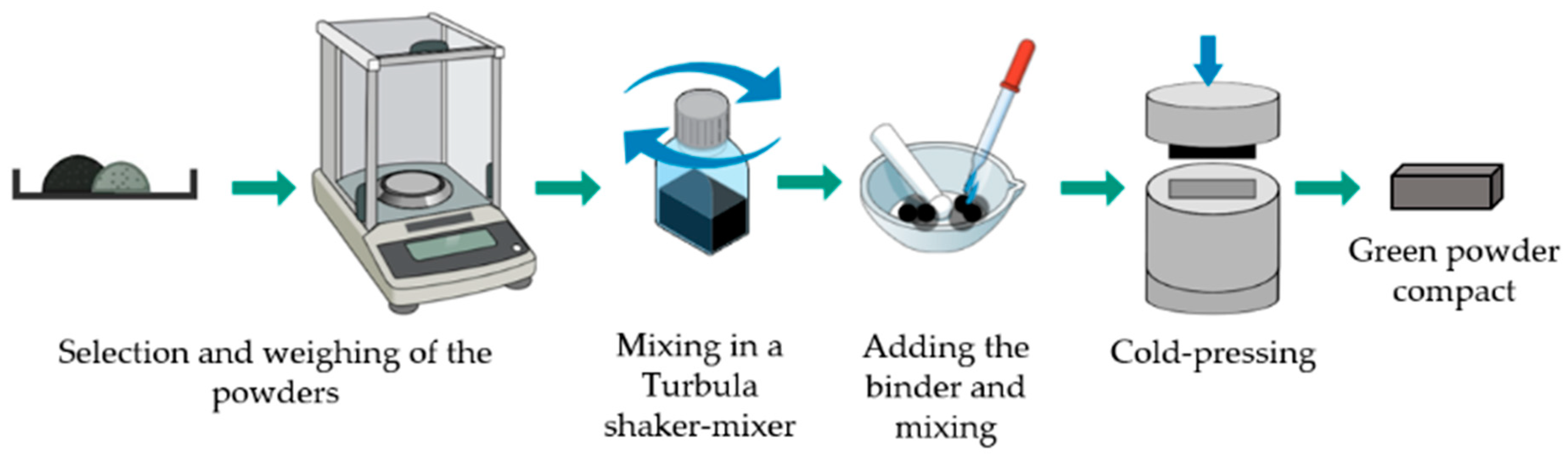
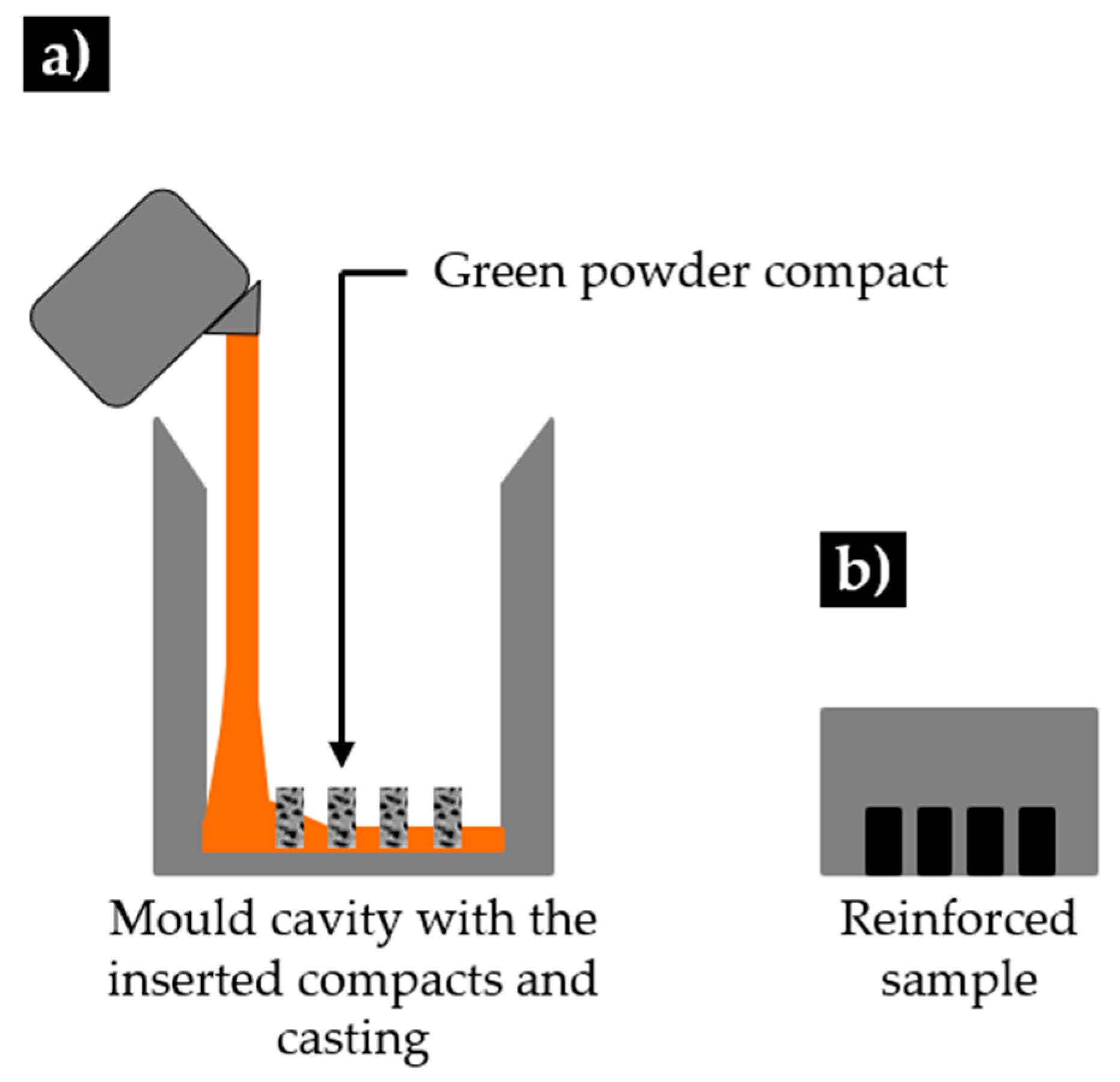
2. Materials and Methods

A technique with several steps was applied to produce the reinforced specimens. This technique is schematically presented in Figure 1 and Figure 2. Commercial powders of WC powders (99.0 wt.% purity) and Fe (99.0 wt.% purity), from Alfa Aesar, ThermoFisher (Kandel, Germany) GmbH were used to produce green compacts to be inserted in the mold cavity. First, the morphology and granulometric distribution of the powders were characterized by scanning electron microscopy (SEM), using a FEI QUANTA 400 FEG (FEI Company, Hillsboro, OR, USA) with an energy-dispersive detector (EDS) and dynamic light scattering (DLS, Laser Coulter LS230 granulometer, Beckman Coulter, Inc., Brea, CA, USA). In the second step, the WC and Fe powders were mixed in a volume fraction of 40:60, which, according to the literature, is within the range that it is expected to guarantee the best wear performance. The mixture was homogenized in Turbula shaker-mixer (Willy A. Bachofen AG, Muttenz, Switzerland) for 7 h, and bound with sodium silicate (1.5 mL). Then, the mixture was uniaxially cold-pressed at approximately 70 MPa in a metallic mold to produce green compacts with dimensions of 31 mm × 12 mm × 7 mm. SEM analysis was performed to study the characteristics of both the powder mixtures and the green compacts. The composition of the mixture was selected from data the literature.
In the final step, the green compacts were inserted in the mold cavity, and the high-chromium white cast iron, melted in a medium frequency induction furnace with a capacity of up to 1000 kg, was poured at a temperature of 1460 °C. The nominal chemical composition of the base metal (see Table 1) was analyzed by optical emission spectrometry (MAXx LMM05, Spectro, Germany).
A cross-section of the specimen was cut by wire electrical discharge for visual control of the inner zones of the composite and the bonding between the composite and the base metal. Metallographic samples were prepared and etched with Beraha-Martensite reagent. The microstructure was characterized by optical microscopy (OM) using a Leica DM 4000M with a DFC 420 camera (Leica Microsystems, Wetzlar, Germany) and SEM secondary electron (SE) and backscattered electron (BSE) image. Electron backscatter diffraction (EBSD) analysis has been used to assist with phase identification. The data obtained from EBSD were submitted to a dilation clean-up procedure, using a grain tolerance angle of 15° and the minimum grain size of 10 points, to avoid inaccurate predictions.
A detailed characterization of the phases formed was performed in transmission electron microscopy (TEM) using a JEOL 2100 (JEOL Ltd., Akishima, Tokyo) operated at 200 keV. For that, thin foils were prepared in a dual-beam focused ion beam (FIB) FEI Helios NanoLab 450S (FEI Company, Hillsboro, OR, USA). On TEM, the phases were fully identified through selected area electron diffraction (SAED). X-ray diffraction (XRD, Cu Kα radiation, Bruker D8 Discover), with a scanning range (2θ) of 20° to 100°, was used to complement the characterization of the phases.

3. Results and Discussion

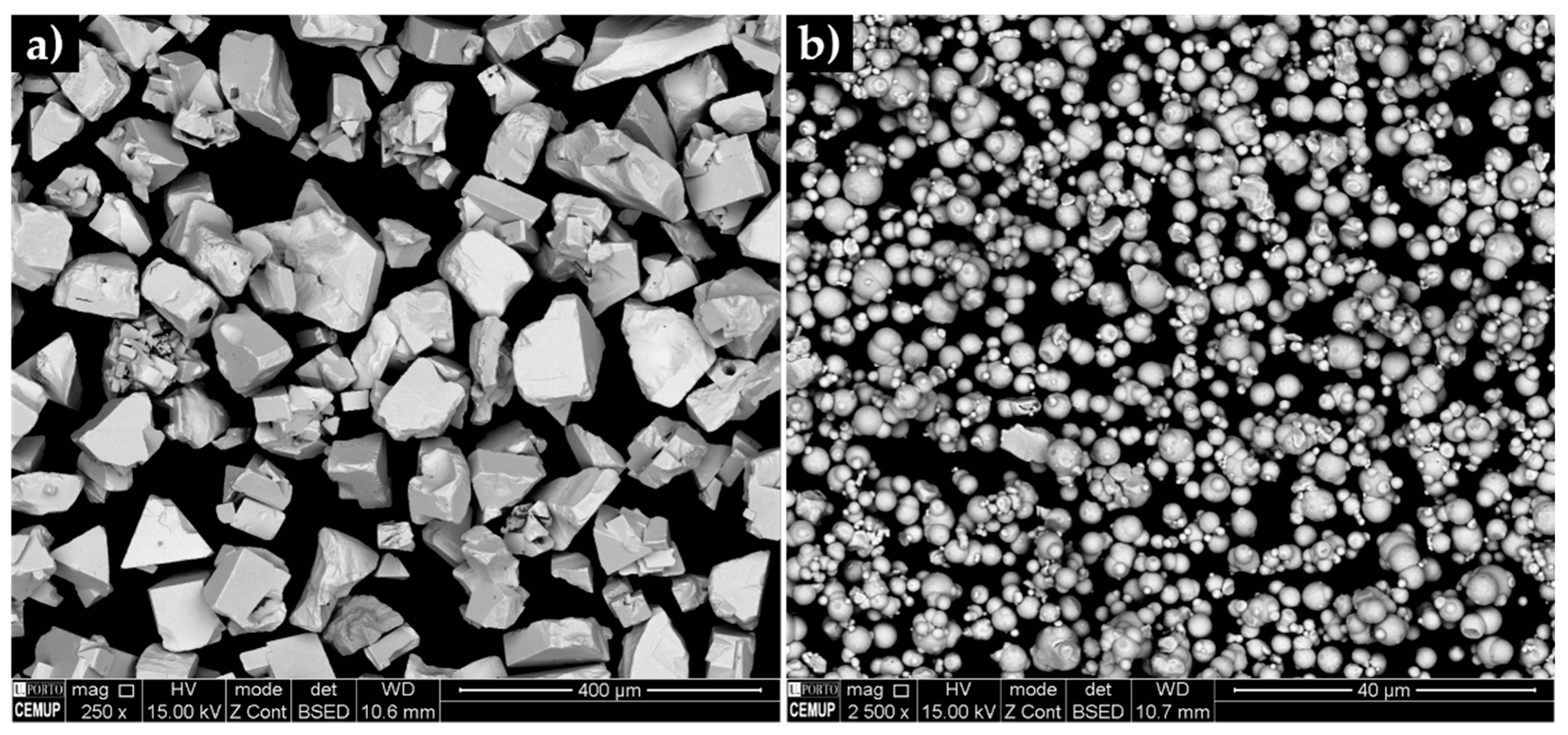
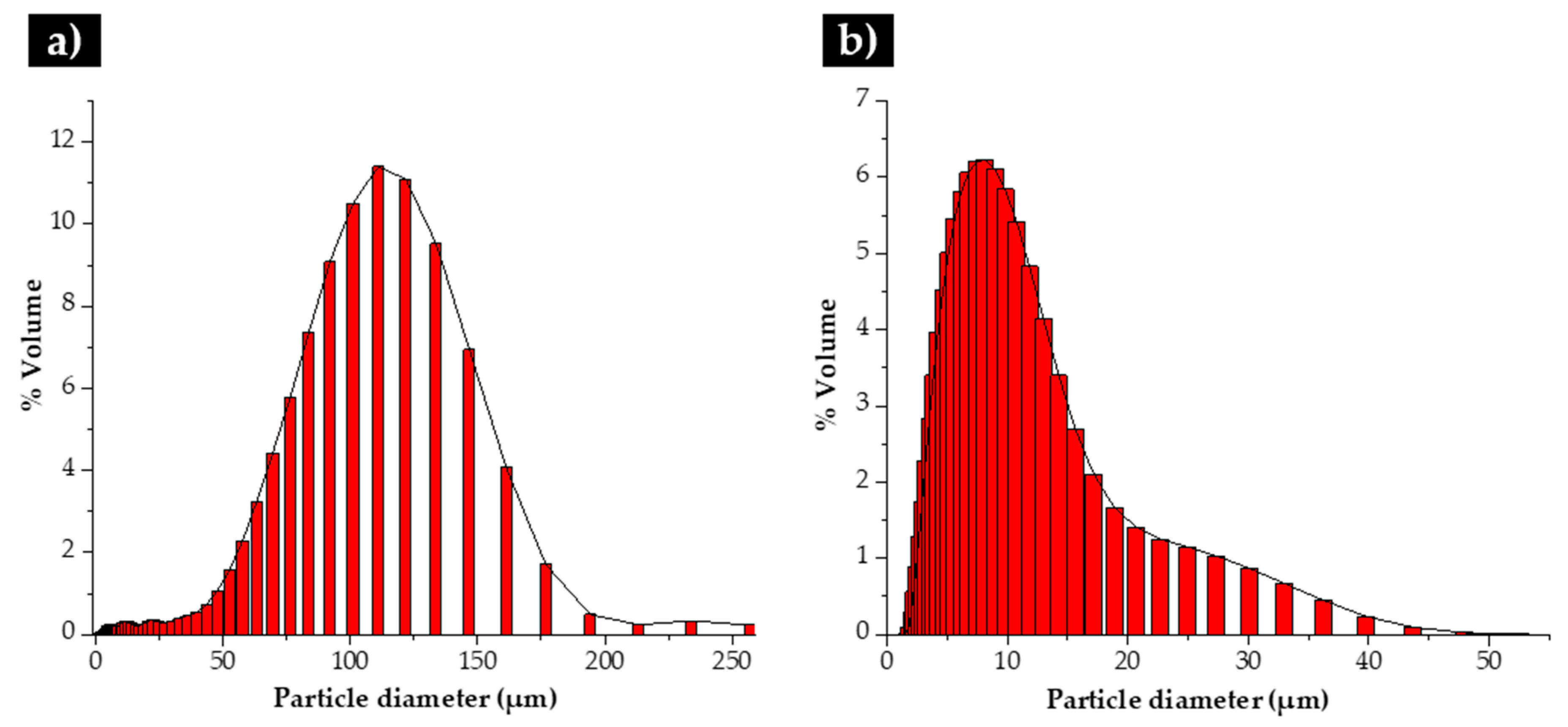
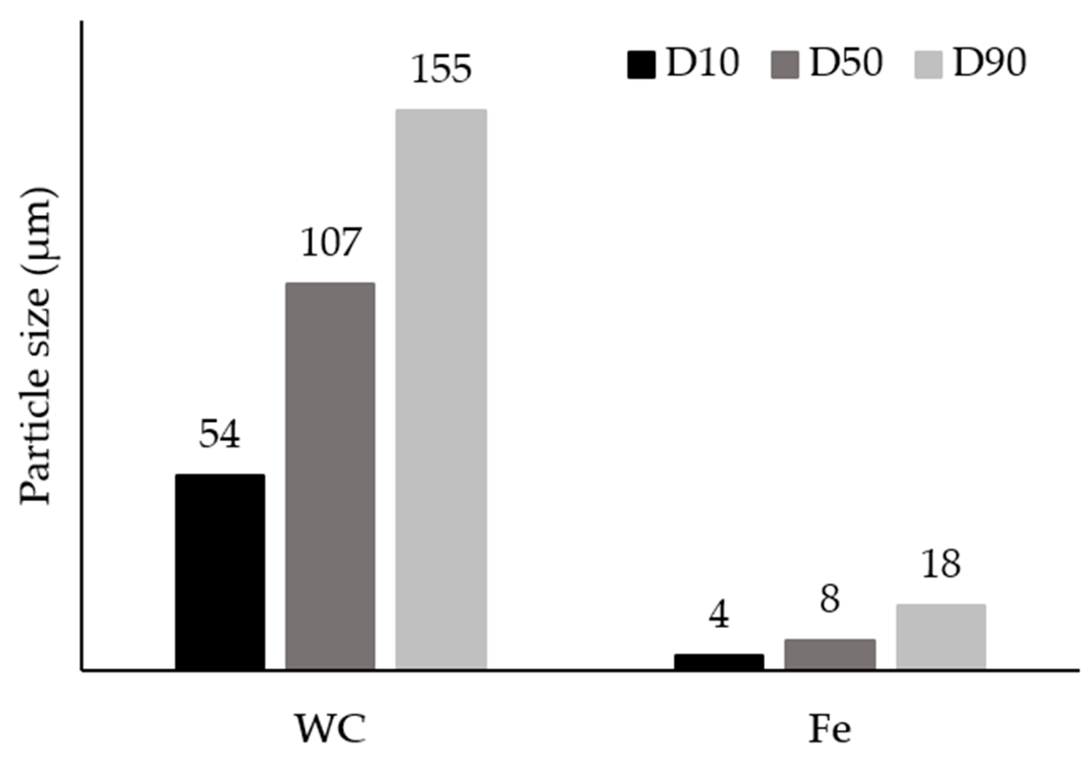
3.1. Characterization of the Initial Powders

The initial powders were first characterized. Their morphological aspect and size distribution are presented in Figure 3, Figure 4 and Figure 5. From these figures, it is possible to see that WC and Fe powders exhibited different size, shape and granulometric distribution. The WC powders (see Figure 3a) exhibit a roughly polyhedral shape, an average size of 106 µm and a D50 of 107 µm (Figure 4a and Figure 5). These results are consistent with the supplier’s specifications (particle size between 53 and 149 µm). The Fe powders exhibit a spherical shape (Figure 3b), an average size of 10 µm and a D50 of 8 µm (Figure 4b and Figure 5). To note that, in this case, the results are significantly different from those of the supplier’s specification (particle average size of 74 µm).

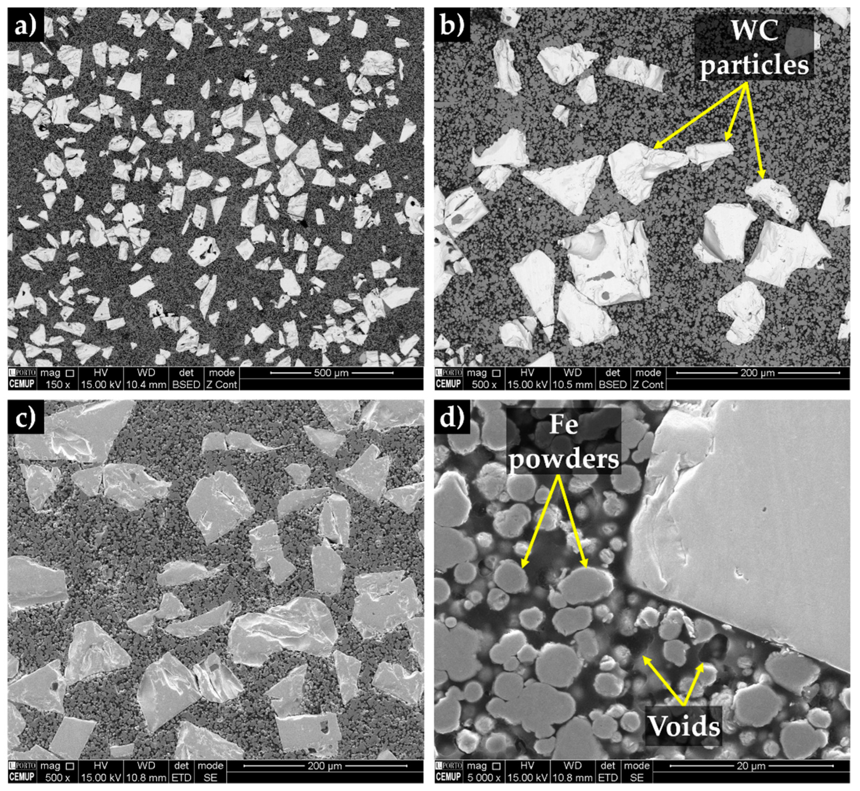
3.2. Characterization of the Green Compacts

The SEM cross-section images of the compacted powders show white particles of WC, gray particles of Fe (see Figure 6a,b) and dark regions corresponding to the binder phase. Using secondary electron (SE) contrast (see Figure 6c,d), it is possible to observe the presence of voids, which may be useful for the liquid metal infiltration. It can be seen that the binder has spread over the WC particles.

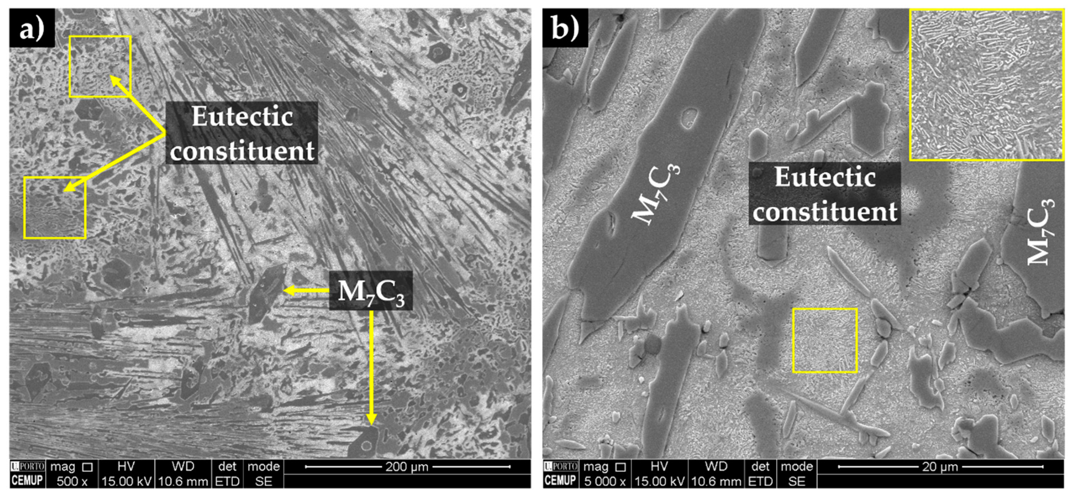
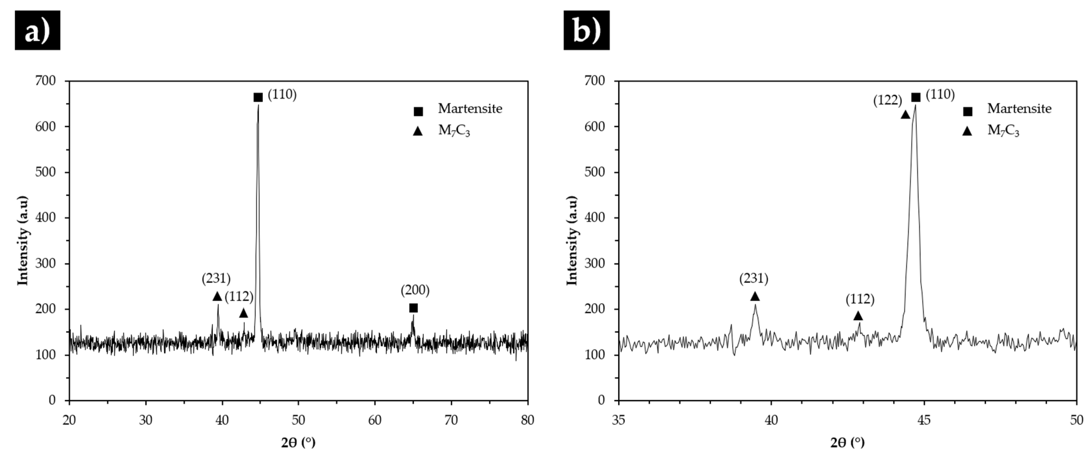
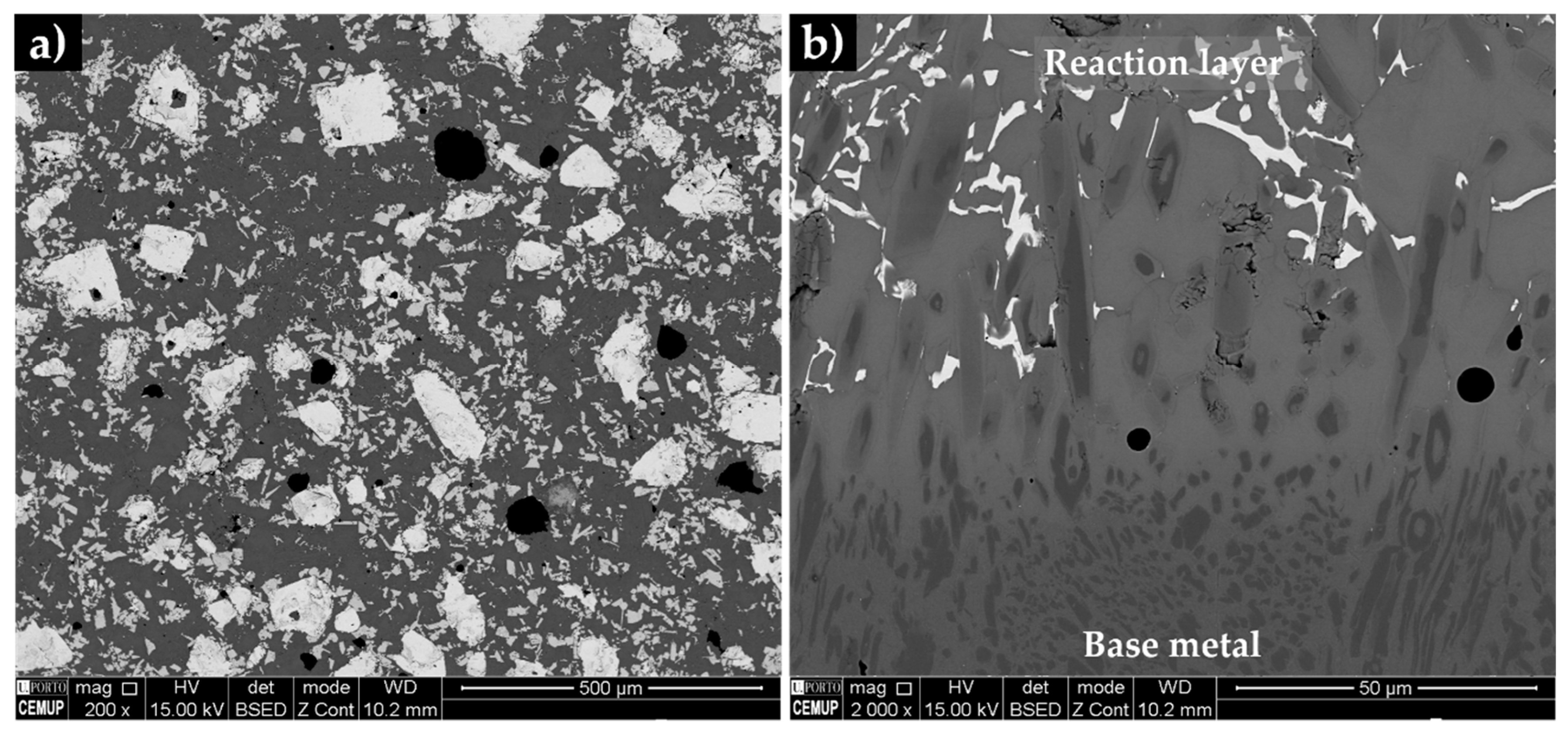
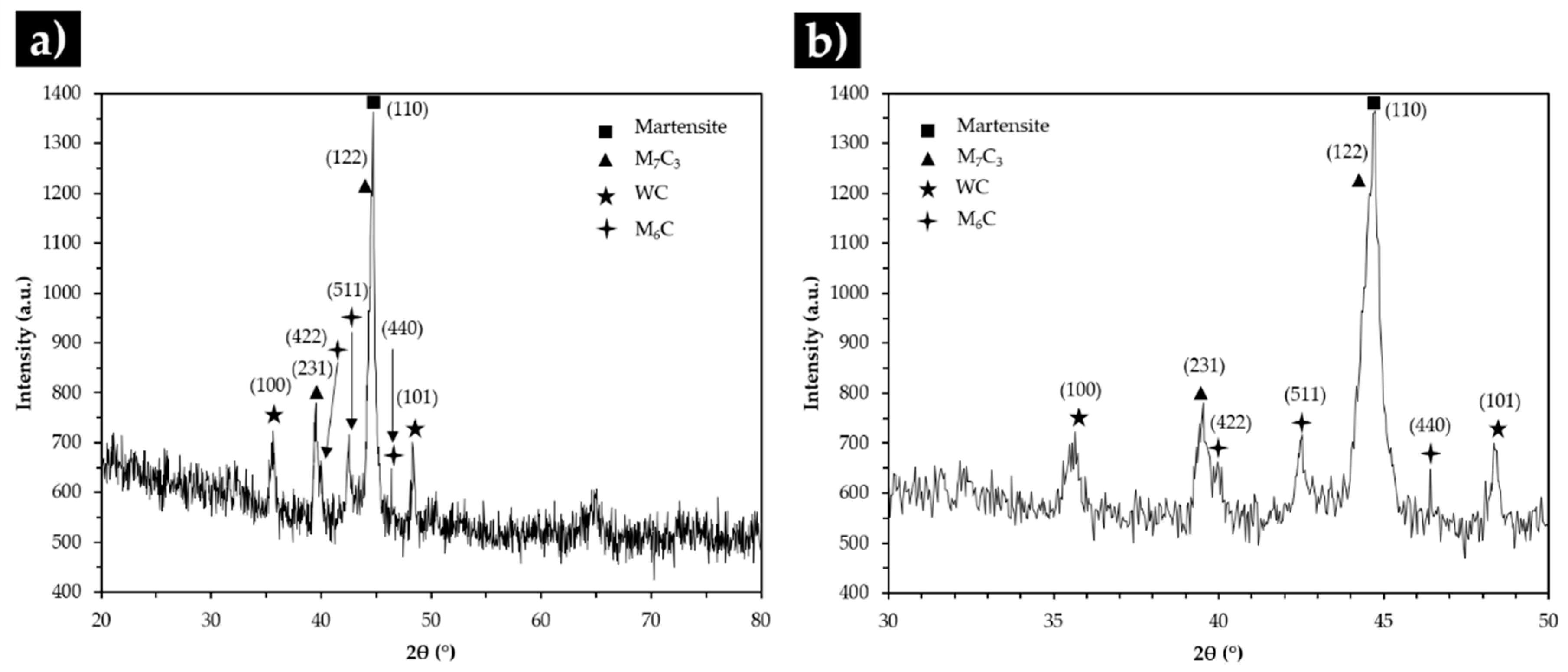
3.3. Characterization of the Base Metal

The chemical composition of the base metal, which is classified as an abrasion-resistant cast iron of class III and type A [41] can be found in Table 1.
The SEM analysis of the base metal (see Figure 7) revealed large Cr-rich carbides with rod-like structure and eutectic constituent, certainly formed from the eutectic reaction L γ + ( F e , C r ) 7 C 3 [1,2,42]. The plate morphology of the eutectic constituent (observed in Figure 7b) can be explained by the transformation of the austenite on cooling. To clarify this topic, the microstructure was investigated by X-ray diffraction and indexing Kikuchi patterns, using EBSD. The XRD patterns of the base metal presented in Figure 8 provided the evidence for the presence of martensite and Cr-rich carbides with the stoichiometry of M7C3.
The EBSD results showed in Figure 9, point out the presence of martensite (Figure 9b), Cr-rich M7C3 carbides (Figure 9d) and also γ phase in some regions, as can be seen in Figure 9c. This phase was not detected in the XRD patterns, indicating that at least its content is less that the detection limit.
In addition to the indexed Kikuchi patterns, the EBSD phase maps of the microstructure were calculated, as shown in Figure 10. The images confirm the previous observations, with the presence of martensite, carbides and austenite being evident. This observation is confirmed by the image quality map (see Figure 10c) that guarantees the accuracy of the diffraction patterns [43].
TEM analysis of thin foils prepared from base metal confirmed the presence of martensite (α’). Figure 11a shows plate martensite (α’) with distinct contrasts that can be attributed to the high density of twins. A particular region showing an interface between α’ and a particle of M7C3 is presented in Figure 11b. The SAED pattern taken from the particle in shown in Figure 11d. In Figure 11c another interesting aspect can be observed, which is the twin-double-diffraction effect detected in the [110]α’ SAED pattern, revealing a BCC {112} <111>-type twins. In this region, extra diffraction spots at 1/3 (−112) and 2/3 (−112) positions, indicated the presence of ω-Fe, which is a metastable hexagonal nano-phase (see yellow spots). The occurrence of ω-Fe phase has been reported to be associated with twinned martensite [44,45,46,47].

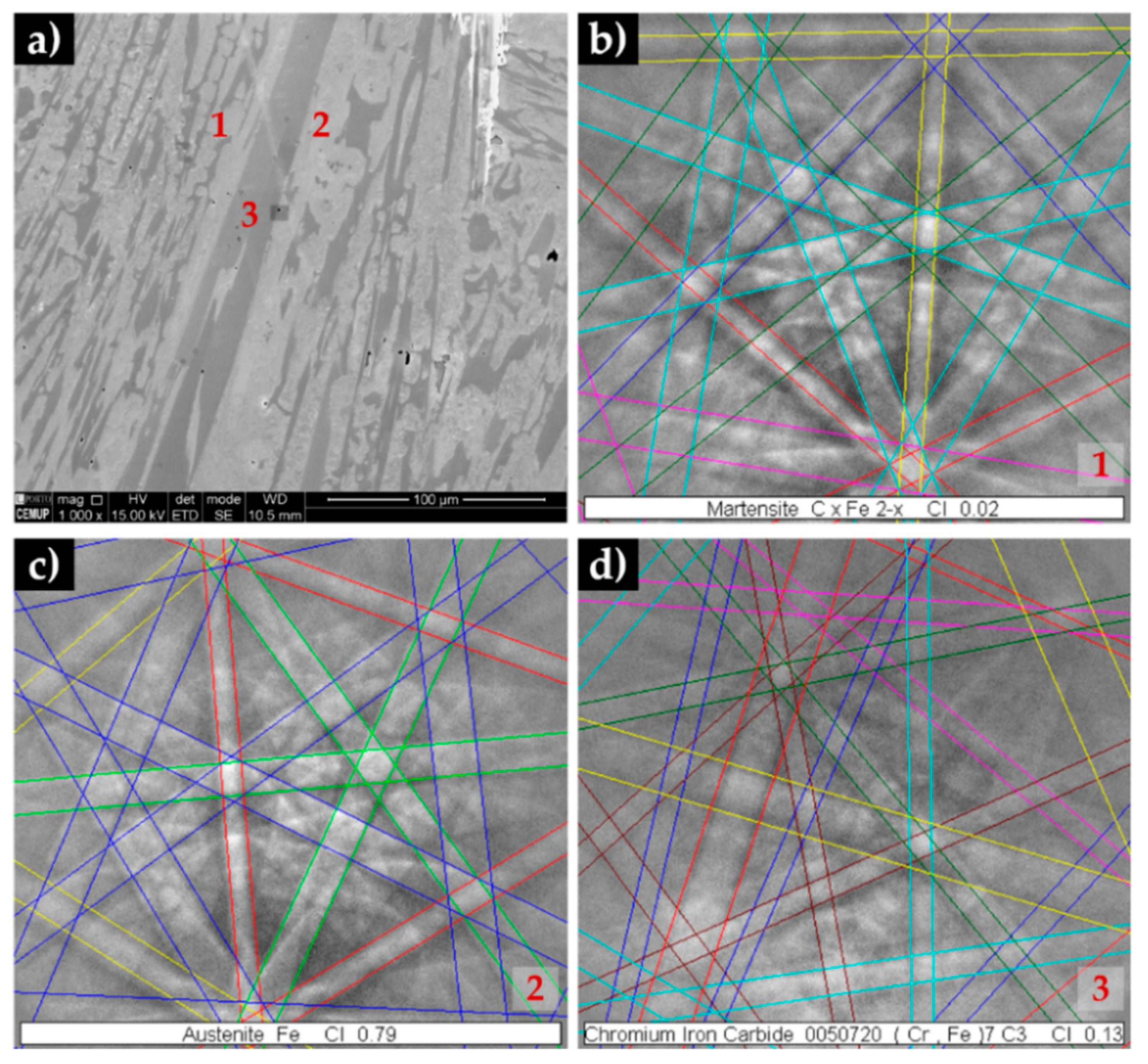
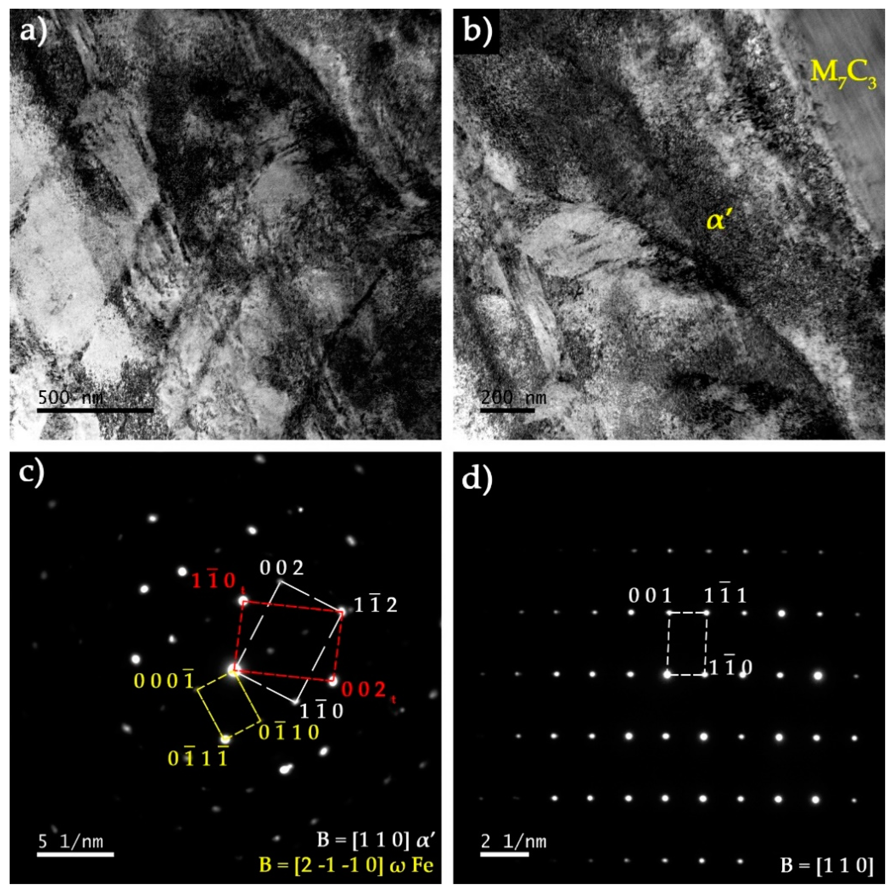
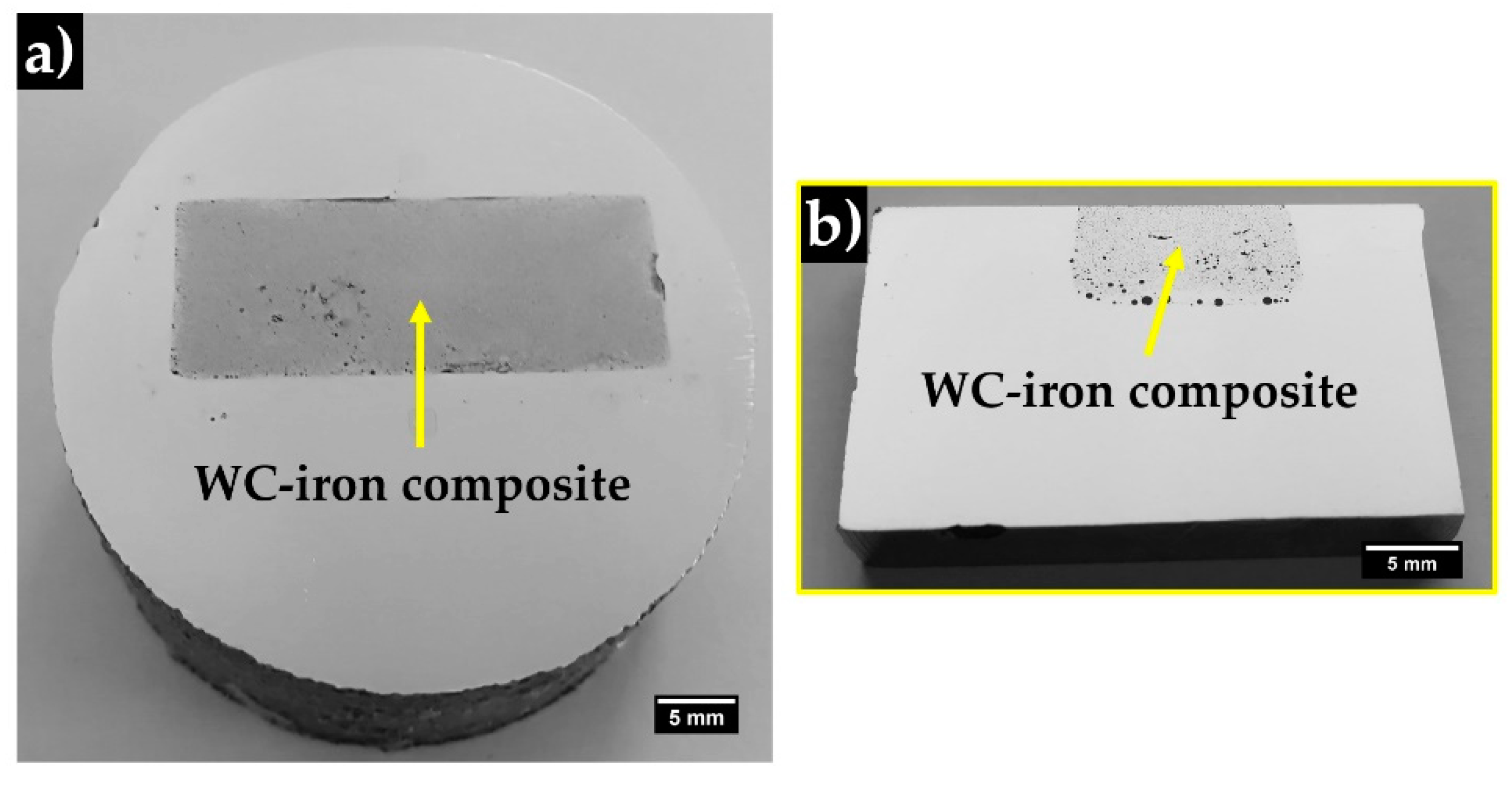
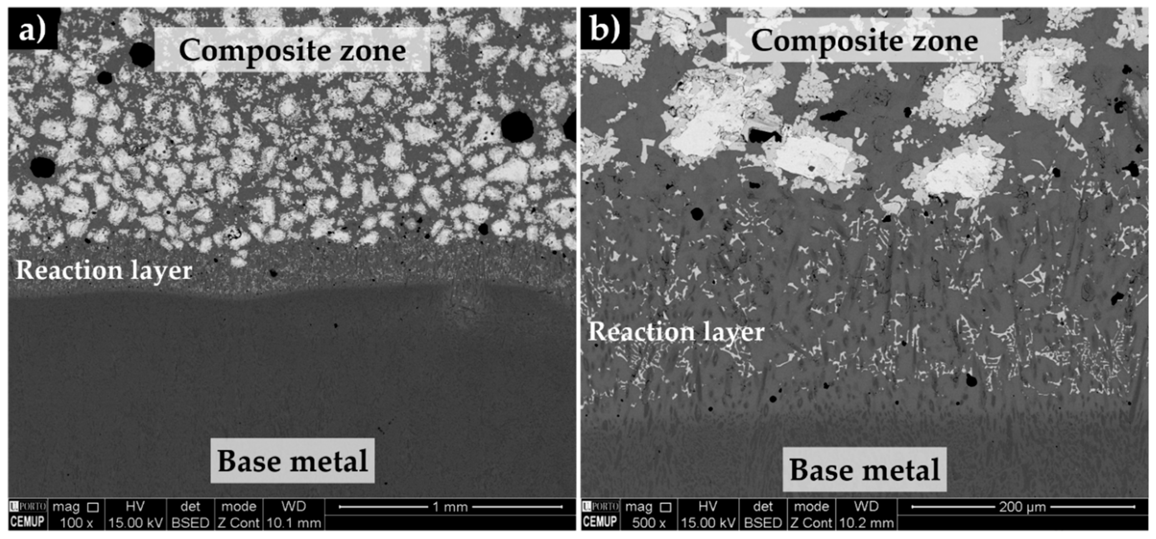
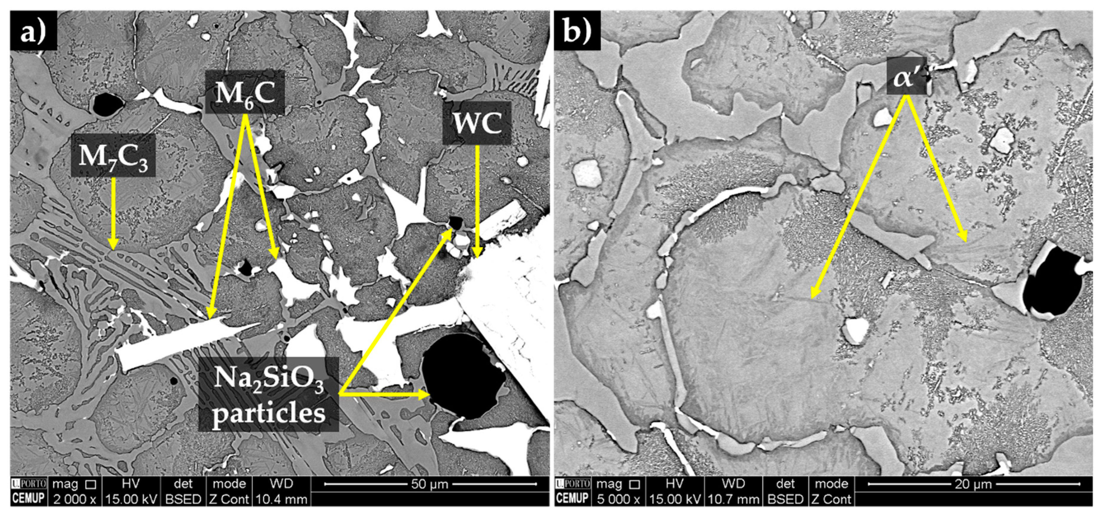
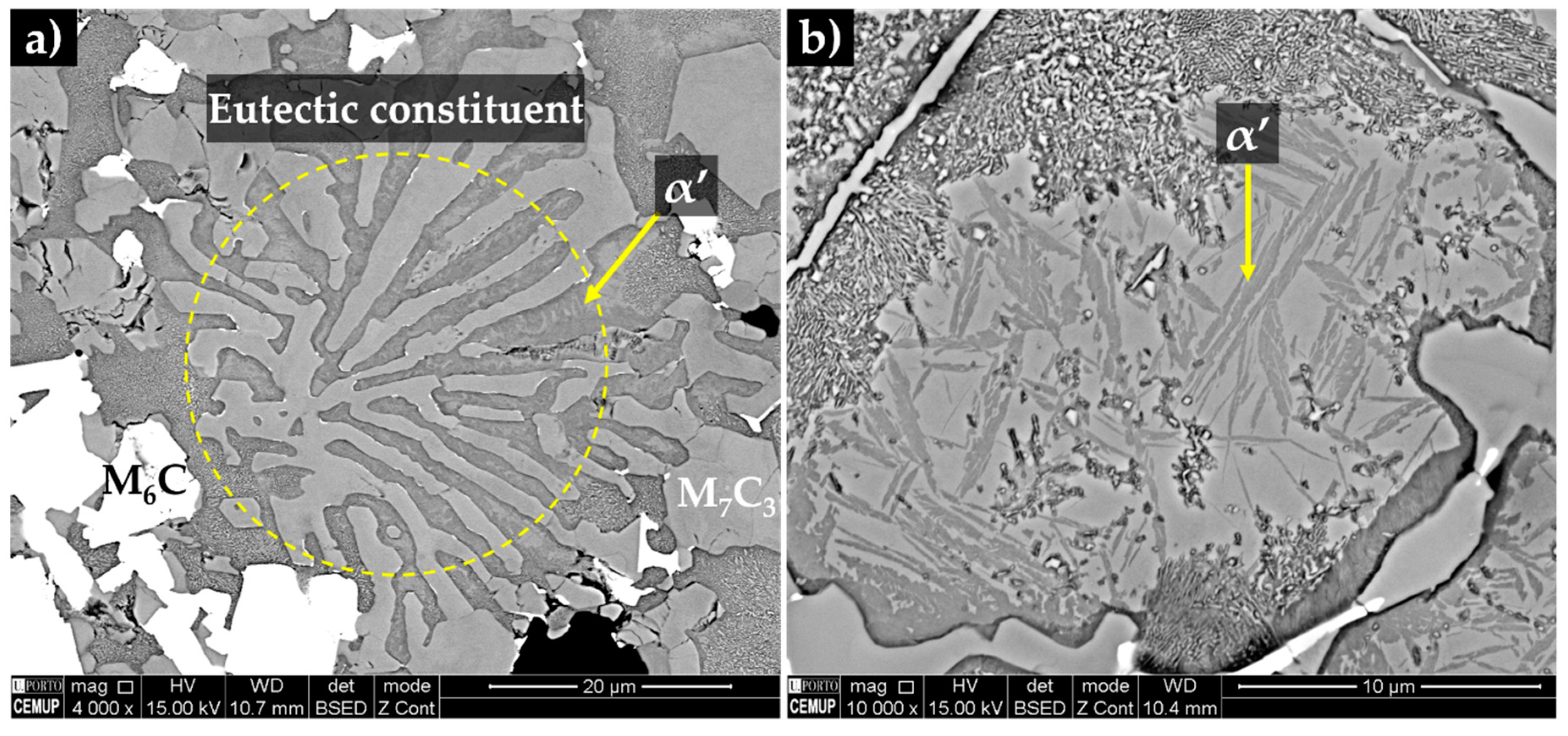
3.4. Characterization of the Reinforced Specimens

The reinforced cast specimen and a cross-section are presented in Figure 12. In the polished surface, it is possible to distinguish two zones, which are the composite (gray zone) and the high-Cr WCI (light-gray zone). The composite zone exhibits a length and a width of around 31 mm and 12 mm, respectively, and a nearly uniform depth (5 mm), which are close to the green compact dimensions.
The microstructure of the composite and the interface bonding of the composite and the base metal is shown in Figure 13. The bonding interface is free of any discontinuities, such as voids and porosities, suggesting that a good infiltration of the molten metal into the green compact was obtained. Furthermore, the reaction layer between the composite and the base metal is around 200 µm, as could be seen in Figure 13b, suggesting a strong bonding between the composite and the base metal.
The composite matrix is shown in Figure 14, the microstructure is characterized by a homogeneous and random distribution of white particles with a polygonal shape and larger dimension (typically between 50 and 200 µm) and small light gray particles (less than 10 µm) with an irregular shape. Elemental mapping analysis (Figure 15) confirmed that both larger and smaller particles are rich in W (in red), suggesting that they are a type of W carbide. The small particles also contain Cr (in pink) and Fe (in blue) in their composition. Note that the dark grey particles of the reaction layer are rich in Cr. The EDS results of the matrix were found to be similar to that of the base metal, with zones rich in Fe and others rich in Cr corresponding to Cr carbides.
The XRD analysis (see Figure 16) permitted to identify the presence of WC, (Fe,Cr)7C3 and (Fe,W,Cr)6C phases in the reaction layer and composite zone. By combining with EDS analysis, one can deduce that the (Fe,W,Cr)6C particles have precipitated from the molten metal that surrounded and partially dissolved the WC carbides. Moreover, the precipitation of (Fe,W,Cr)6C carbides along with the reduction of Cr and C in the molten metal, leads to the hypoeutectic solidification structure, consisting of primary austenite and eutectic constituent with a network morphology that can be observed in Figure 17. Based on XRD and EDS analysis, the eutectic constituent is composed by two types of carbides: (Fe,Cr)7C3 and (Fe,W,Cr)6C and γ that transforms into martensite during the subsequent cooling (see Figure 17b and Figure 18). In Figure 17, it is also possible to observe the presence of black globules, that correspond to the sodium silicate particles, suggesting that the binder used has remelted and crystalized during the casting process due to the heat released by the liquid metal [25].
TEM/SAED analysis was performed to further characterize the microstructural features of the constituents of the composite zone. Figure 19a shows the martensite matrix next to a large (Fe,W,Cr)6C particle. The contrast level of the martensite varies from light grey to black gray due to the high density of twins in the plate structure. In addition, thin plate-like M23C6 carbides that may have precipitated from martensite were observed in some localized regions (see Figure 19b).

4. Conclusions

High-Cr WCI specimens locally reinforced with WC–metal matrix composites were successfully produced via an ex-situ technique, using powder mixtures of WC and Fe and Na2SiO3 as a binder. The nonexistence of voids and porosities in the composite zone suggests a good infiltration of the molten metal into the inserted green compact. Moreover, the presence of a defect-free reaction zone, with about 200 µm of thickness, between the base metal and the composite zones should guarantee a strong bonding between these two regions. The microstructure of the composite zone shows a matrix with WC and (Fe,W,Cr)6C. The (Fe,W,Cr)6C precipitation was accompanied by a reduction of Cr in the base metal, leading to a hypoeutectic solidification. The final microstructure of the matrix is martensite and a eutectic constituent, composed of martensite and two types of carbides: (Fe,Cr)7C3 and (Fe,W,Cr)6C.

Author Contributions

Conceptualization, A.B.M.; formal analysis, L.M.M.R., A.M.P.P. and M.F.V.; funding acquisition, M.F.V.; investigation, A.B.M., P.L. and R.O.S.; supervision, L.M.M.R., A.M.P.P. and M.F.V.; validation, L.M.M.R. and M.F.V.; writing—original draft, A.B.M. and R.O.S.; writing—review and editing, L.M.M.R., A.M.P.P. and M.F.V. All authors read and agreed to the published version of the manuscript.

Funding

This research was funded by FEDER through the program P2020|COMPETE, Projetos em Copromoção (project POCI-01-0247-FEDER-033417), and the program P2020|Norte2020, Programas doutorais (NORTE-08-5369-FSE-000051).

Acknowledgments

The authors are grateful to CEMUP (Centro de Materiais da Universidade do Porto) for expert assistance with SEM. This work was carried out in part through the use of the INL Advanced Electron Microscopy, Imaging, and Spectroscopy Facility.

Conflicts of Interest

The authors declare no conflict of interest.

References

  1. Doğan, Ö.; Hawk, J.; Laird, G. Solidification structure and abrasion resistance of high chromium white irons. Metall. Mater. Trans. A 1997, 28, 1315–1328. [Google Scholar] [CrossRef]
  2. Tabrett, C.P.; Sare, I.R.; Ghomashchi, M.R. Microstructure-property relationships in high chromium white iron alloys. Int. Mater. Rev. 1996, 41, 59–82. [Google Scholar] [CrossRef]
  3. Heino, V.; Kallio, M.; Valtonen, K.; Kuokkala, V.-T. The role of microstructure in high stress abrasion of white cast irons. Wear 2017, 388, 119–125. [Google Scholar] [CrossRef]
  4. Karantzalis, E.; Lekatou, A.; Mavros, H. Microstructure and properties of high chromium cast irons: Effect of heat treatments and alloying additions. Int. J. Cast Met. Res. 2009, 22, 448–456. [Google Scholar] [CrossRef]
  5. Davis, J.R.; Committee, A.S.M.I.H. Metallurgy and Properties of High-Alloy White Irons. In ASM Specialty Handbook: Cast Irons; Davis, J.R., Ed.; ASM International: Materials Park, OH, USA, 1996; pp. 107–122. [Google Scholar]
  6. Wiengmoon, A.; Pearce, J.; Chairuangsri, T. Relationship between microstructure, hardness and corrosion resistance in 20 wt.%Cr, 27 wt.%Cr and 36 wt.%Cr high chromium cast irons. Mater. Chem. Phys. 2011, 125, 739–748. [Google Scholar] [CrossRef]
  7. Carpenter, S.; Carpenter, D.; Pearce, J. XRD and electron microscope study of an as-cast 26.6% chromium white iron microstructure. Mater. Chem. Phys. 2004, 85, 32–40. [Google Scholar] [CrossRef]
  8. Bedolla-Jacuinde, A.; Arias, L.; Hernández, B. Kinetics of secondary carbides precipitation in a high-chromium white iron. J. Mater. Eng. Perform. 2003, 12, 371–382. [Google Scholar] [CrossRef]
  9. Tang, S.; Gao, Y.; Li, Y. Recent developments in fabrication of ceramic particle reinforced iron matrix wear resistant surface composite using infiltration casting technology. Ironmak. Steelmak. 2014, 41, 633–640. [Google Scholar] [CrossRef]
  10. Hou, S.; Bao, C.; Zhang, Z.; Bai, Y. Microstructure and Wear Behavior of High-Cr WCI Matrix Surface Composite Reinforced with Cemented Carbide Rods. J. Mater. Eng. Perform. 2013, 22, 2064–2072. [Google Scholar] [CrossRef]
  11. Kambakas, K.; Tsakiropoulos, P. Sedimentation casting of wear resistant metal matrix composites. Mater. Sci. Eng. A 2006, 435, 187–192. [Google Scholar] [CrossRef]
  12. Zhang, P.; Zeng, S.; Zhang, Z.; Li, W. Microstructure and hardness of WC-Co particle reinforced iron matrix surface composite. China Foundry 2013, 10, 374–379. [Google Scholar]
  13. Li, Z.; Jiang, Y.; Zhou, R.; Chen, Z.; Shan, Q.; Tan, J. Effect of Cr addition on the microstructure and abrasive wear resistance of WC-reinforced iron matrix surface composites. J. Mater. Res. 2014, 29, 778–785. [Google Scholar] [CrossRef]
  14. Leibholz, R.; Robert, M.H.; Leibholz, H.; Bayraktar, E. Development of functionally graded nodular cast iron reinforced with recycled WC particles. In Mechanics of Composite and Multi-functional Materials; Springer: Cham, Switzerland, 2017; Volume 7, pp. 241–249. [Google Scholar]
  15. Kambakas, K.; Tsakiropoulos, P. Solidification of high-Cr white cast iron–WC particle reinforced composites. Mater. Sci. Eng. A 2005, 413, 538–544. [Google Scholar] [CrossRef]
  16. Niu, L.; Xu, Y.; Wang, X. Fabrication of WC/Fe composite coating by centrifugal casting plus in-situ synthesis techniques. Surf. Coat. Technol. 2010, 205, 551–556. [Google Scholar] [CrossRef]
  17. Zhang, Z.; Chen, Y.; Zuo, L.; Zhang, Y.; Qi, Y.; Gao, K.; Liu, H.; Wang, X. In situ synthesis WC reinforced iron surface composite produced by spark plasma sintering and casting. Mater. Lett. 2018, 210, 227–230. [Google Scholar] [CrossRef]
  18. Pierson, H.O. Carbides of Group VI: Chromium, Molybdenum, and Tungsten Carbides. In Handbook of Refractory Carbides and Nitrides: Properties, Characteristics, Processing and Applications; Noyes Publications: Westwood, NJ, USA, 1996; pp. 100–117. [Google Scholar] [CrossRef]
  19. CES EduPack—Database: Level 3, 19.1.0; Granta Design Limited: Cambridge, UK, 2019.
  20. Zhou, R.; Jiang, Y.; Lu, D. The effect of volume fraction of WC particles on erosion resistance of WC reinforced iron matrix surface composites. Wear 2003, 255, 134–138. [Google Scholar] [CrossRef]
  21. Cuevas, A.C.; Becerril, E.B.; Martínez, M.S.; Ruiz, J.L. Fabrication Processes for Metal Matrix Composites. In Metal Matrix Composites: Wetting and Infiltration; Springer: Cham, Switzerland, 2018; pp. 83–114. [Google Scholar] [CrossRef]
  22. Manu, K.S.; Raag, L.A.; Rajan, T.; Gupta, M.; Pai, B. Liquid Metal Infiltration Processing of Metallic Composites: A Critical Review. Metall Mater Trans B 2016, 47, 2799–2819. [Google Scholar] [CrossRef]
  23. Chawla, N.; Chawla, K.K. Processing. In Metal Matrix Composites, 2nd ed.; Springer: New York, NY, USA, 2013; pp. 55–97. [Google Scholar] [CrossRef] [Green Version]
  24. Cao, G.J.; Guo, E.J.; Feng, Y.C.; Wang, L.P. Abrasion Behavior of WC Reinforced Cast Iron Surface Composite Fabricated by Cast-Infiltration Method. In Advanced Materials Research; Trans Tech Publications Ltd.: Switzerland, 2012; pp. 555–559. [Google Scholar]
  25. Aso, S.; Goto, S.; Komatsu, Y.; Ike, H.; Shimizu, K. Composite reinforcement of the surface of cast iron by WC powder inserts. Int. J. Cast Met. Res. 2003, 16, 345–350. [Google Scholar] [CrossRef]
  26. Leibholz, R.; Leibholz, H.; Bayraktar, E.; Robert, M.H. Investigation on Microstructure and Interfaces in Graded FE50007/WC Composites Produced by Casting. In Mechanics of Composite, Hybrid and Multifunctional Materials; Springer: Cham, Switzerland, 2019; Volume 5, pp. 321–329. [Google Scholar]
  27. Zhang, G.-S.; Xing, J.-D.; Gao, Y.-M. Impact wear resistance of WC/Hadfield steel composite and its interfacial characteristics. Wear 2006, 260, 728–734. [Google Scholar] [CrossRef]
  28. Zhang, G.S.; Gao, Y.M.; Xing, J.D.; Wei, S.Z.; Zhang, X.L. Interfacial Characteristics and Wear Resistance of WCp/White-Cast-Iron Composites. Adv. Mater. Res. 2007, 26–28, 293–296. [Google Scholar] [CrossRef]
  29. Song, Y.; Wang, H. High speed sliding wear behavior of recycled WCP-reinforced ferrous matrix composites fabricated by centrifugal cast. Wear 2012, 276–277, 105–110. [Google Scholar] [CrossRef]
  30. Chumanov, I.; Anikeev, A.; Chumanov, V. Fabrication of functionally graded materials by introducing wolframium carbide dispersed particles during centrifugal casting and examination of FGM’s structure. Procedia Eng. 2015, 129, 816–820. [Google Scholar] [CrossRef] [Green Version]
  31. Niu, L.; Hojamberdiev, M.; Xu, Y. Preparation of in situ-formed WC/Fe composite on gray cast iron substrate by a centrifugal casting process. J. Mater. Process. Technol. 2010, 210, 1986–1990. [Google Scholar] [CrossRef]
  32. Zheng, K.; Gao, Y.; Tang, S.; Li, Y.; Ma, S.; Yi, D.; Zhang, Z. Interface Structure and Wear Behavior of Cr26 Ferrous Matrix Surface Composites Reinforced with CTCp. Tribol. Lett. 2014, 54, 15–23. [Google Scholar] [CrossRef]
  33. Li, Y.; Gao, Y. Three-body abrasive wear behavior of CC/high-Cr WCI composite and its interfacial characteristics. Wear 2010, 268, 511–518. [Google Scholar] [CrossRef]
  34. Shan, Q.; Li, Z.; Jiang, Y.; Zhou, R.; Sui, Y. Effect of Ni addition on microstructure of matrix in casting tungsten carbide particle reinforced composite. J. Mater. Sci. Technol. 2013, 29, 720–724. [Google Scholar] [CrossRef]
  35. Li, Z.L.; Chen, Z.H.; Jiang, Y.H.; Zhou, R.; Shan, Q.; Song, Q.L. Influence of Addition of Tungsten-iron powder on Microstructure of WC/steel Composite Coatings. In Advanced Materials Research; Trans Tech Publications Ltd.: Zurich, Switzerland, 2012; pp. 394–398. [Google Scholar]
  36. Li, Z.; Jiang, Y.; Zhou, R.; Gao, F.; Shan, Q.; Tan, J. Thermal fatigue mechanism of WC particles reinforced steel substrate surface composite at different thermal shock temperatures. J. Alloys Compd. 2014, 596, 48–54. [Google Scholar] [CrossRef]
  37. Li, Z.; Jiang, Y.; Zhou, R.; Lu, D.; Zhou, R. Dry three-body abrasive wear behavior of WC reinforced iron matrix surface composites produced by V-EPC infiltration casting process. Wear 2007, 262, 649–654. [Google Scholar] [CrossRef]
  38. Huang, R.Q.; Li, Z.L.; Jiang, Y.H.; Zhou, R.; Gao, F. Thermal Shock Cracks Initiation and Propagation of WCp/Steel Substrate Surface Composite at 500 °C. Appl. Mech. Mater. 2012, 109, 253–260. [Google Scholar] [CrossRef]
  39. Sui, Y.; Han, L.; Jiang, Y.; Li, Z.; Shan, Q. Effects of Ni60WC25 powder content on the microstructure and wear properties of WCp reinforced surface metal matrix composites. Trans. Indian Inst. Met. 2018, 71, 2415–2422. [Google Scholar] [CrossRef]
  40. Moreira, A.B.; Sousa, R.O.; Lacerda, P.; Ribeiro, L.M.M.; Pinto, A.M.P.; Vieira, M.F. Microstructural Characterization of TiC–White Cast-Iron Composites Fabricated by In Situ Technique. Materials 2020, 13, 209. [Google Scholar] [CrossRef] [Green Version]
  41. Standard Specification for Abrasion-Resistant Cast Irons. In A532/A532M—10; ASTM International: West Conshohocken, PA, USA, 2010. [CrossRef]
  42. Laird, G.; Gundlach, R.; Rohrig, K. Abrasion-Resistant Cast Iron Handbook; American Foundry Society: Des Plaines, IL, USA, 2000. [Google Scholar]
  43. Suwas, S.; Ray, R.K. Crystallographic Texture of Materials; Derby, B., Ed.; Springer: London, UK; Heidelberg, Germany; New York, NY, USA; Dordrecht, The Netherlands, 2014. [Google Scholar] [CrossRef]
  44. Liu, T.; Ping, D.; Ohmura, T.; Ohnuma, M. Electron diffraction analysis of quenched Fe–C martensite. J. Mater. Sci. 2018, 53, 2976–2984. [Google Scholar] [CrossRef]
  45. Ping, D.; Guo, S.; Imura, M.; Liu, X.; Ohmura, T.; Ohnuma, M.; Lu, X.; Abe, T.; Onodera, H. Lath formation mechanisms and twinning as lath martensite substructures in an ultra low-carbon iron alloy. Sci. Rep. 2018, 8. [Google Scholar] [CrossRef] [Green Version]
  46. Zhang, P.; Chen, Y.; Xiao, W.; Ping, D.; Zhao, X. Twin structure of the lath martensite in low carbon steel. Prog. Nat. Sci. 2016, 26, 169–172. [Google Scholar] [CrossRef] [Green Version]
  47. Ping, D.; Ohnuma, M. ω-Fe particle size and distribution in high-nitrogen martensitic steels. J. Mater. Sci. 2018, 53, 5339–5355. [Google Scholar] [CrossRef]
Figure 1. Scheme of the fabrication steps for the green compacts production.
Materials 13 02596 g001
Figure 2. Scheme of the (a) mold with the inserted green compacts and (b) reinforced specimen (adapted from [40]).
Materials 13 02596 g002
Figure 3. SEM-backscattered electron (BSE) images of the initial powders: (a) WC with polyhedral morphology and (b) round particles of Fe.
Materials 13 02596 g003
Figure 4. Granulometric distribution of the initial powders: (a) WC and (b) Fe.
Materials 13 02596 g004
Figure 5. Analysis of the particle size distribution by dynamic light dispersion (DLS), indicating parameters D10, D50 and D90 of the initial powders.
Materials 13 02596 g005
Figure 6. SEM cross-section images of the green compacts: (a) low, (b and c) medium and (d) high magnification.
Materials 13 02596 g006
Figure 7. SEM-secondary electron (SE) image of the microstructure of the high-Cr WCI in the as-cast condition (a), and at higher magnification (b).
Materials 13 02596 g007
Figure 8. X-ray diffraction (XRD) patterns of the high-Cr WCI in the as-cast condition in the 2θ range of 20°–80° (a) and 35°–50° (b).
Materials 13 02596 g008
Figure 9. SEM-SE image of the base metal in the as-cast condition (a), and indexed EBSD patterns corresponding to the phases that compose the microstructure: α’ (b), γ (c) and M7C3 (d).
Materials 13 02596 g009
Figure 10. SEM image of the microstructure of the base metal (a), phase map: γ in yellow, α’ in blue and M7C3 in green (b) and image quality map (c).
Materials 13 02596 g010
Figure 11. Dark-field TEM image of the base metal showing (a) α’ phase revealing twin contrast and (b) interface between α’ and a Cr-rich M7C3 carbide. The identification of phases was concluded by selected area electron diffraction (SAED) analysis with (c) [110] zone axis of α’ and (d) [110] zone axis of M7C3.
Materials 13 02596 g011
Figure 12. The reinforced cast specimen (a) and a cross-section (b) to highlight the depth of the composite and the interface zone.
Materials 13 02596 g012
Figure 13. SEM-BSE images of the microstructure of the reinforced specimen showing the base metal and composite zone (a) and evidencing the reaction layer (b).
Materials 13 02596 g013
Figure 14. SEM-BSE image of the microstructure of the composite zone, showing a uniform distribution of the carbide particles (a) and the reaction layer, evidencing a bonding interface free of discontinuities (b).
Materials 13 02596 g014
Figure 15. SEM-BSE images of the microstructure of the reaction layer (a) and composite zone (b). EDS elemental mapping (c-h) of Fe (blue), Cr (pink) and W (red).
Materials 13 02596 g015
Figure 16. XRD patterns of the composite zone in the 2θ range of 20°–80° (a) and 30°–50° (b).
Materials 13 02596 g016
Figure 17. SEM-BSE images of the microstructure of the composite zone; (a) a network of eutectic constituent ((Fe,Cr)7C3 and (Fe,W,Cr)6C + α’), (Fe,W,Cr)6C next to the WC carbides and globules of Na2SiO3 and (b) martensite (α’).
Materials 13 02596 g017
Figure 18. SEM-BSE images of the microstructure of the composite zone, (a) a detailed of a eutectic constituent (Fe,Cr)7C3 and (Fe,W,Cr)6C + α’) and (b) the martensite phase.
Materials 13 02596 g018
Figure 19. Dark-field TEM image of the composite showing (a) an interface between (Fe,W,Cr)6C carbide and α’ phase and (b) an M23C6 carbide embedded in α’. The identification of phases was performed by SAED analysis with (c) [112] zone axis of (Fe,W,Cr)6C and (d) [100] zone axis of α’ and [110] zone axis of M23C6.
Materials 13 02596 g019
Table 1. Nominal chemical composition of the high-Cr white cast iron (WCI) (wt.%).
CSiMnCrNiFe
3.070.780.6526.020.20Balance

