Article

Simulation Studies on Centrifugal MQL-CCA Method of Applying Coolant during Internal Cylindrical Grinding Process

by
Seweryn Kieraś
1,
Marek Jakubowski
2 and
Krzysztof Nadolny
3,*
1
Wartsila Poland Sp. z o.o., Łużycka 2, 81-537 Gdynia, Poland
2
Department of Food Industry Processes and Facilities, Faculty of Mechanical Engineering, Koszalin University of Technology, Racławicka 15-17, 75-620 Koszalin, Poland
3
Department of Production Engineering, Faculty of Mechanical Engineering, Koszalin University of Technology, Racławicka 15-17, 75-620 Koszalin, Poland
*
Author to whom correspondence should be addressed.
Materials 2020, 13(11), 2506; https://doi.org/10.3390/ma13112506
Submission received: 7 April 2020 / Revised: 28 May 2020 / Accepted: 28 May 2020 / Published: 31 May 2020
(This article belongs to the Section Manufacturing Processes and Systems)

Abstract

:
This paper describes simulation studies regarding the application of the centrifugal minimum quantity lubrication (MQL) method simultaneously with the delivery of a compressed cooled air (CCA) stream in the internal cylindrical grinding process. The idea of a new hybrid cooling and lubrication method connecting centrifugal (through a grinding wheel) lubrication by MQL with a CCA stream is described. The methodology of computational fluid dynamics (CFD) simulation studies, as well as the results of numerical simulations, are presented in detail. The aim of the simulations was to determine the most favourable geometrical and kinematic parameters of the system in the context of air-oil aerosol and CCA flow, as well as heat exchange. In the simulation, the variables were the grinding arbor geometrical parameters, the angle of CCA supply line outlets, and the grinding wheel and workpiece peripheral speed. As a result of the simulation studies, the most favourable geometrical parameters were designated, determining the orientation of the ends of the two CCA supply line outlets before and after the grinding zone, the number of openings in the drilled-out grinding arbor, and the influence of the grinding speed on the parameters of the coolant flow and temperature of objects in the grinding zone. In addition, the results of simulation tests made it possible to visualise the velocity vectors of the two-phase coolant flow in a complex system of air-oil aerosol delivery centrifugally through an open structure of a very fast rotating porous layer (grinding wheel), with an additional supply of CCA using an external cold air gun (CAG).

1. Introduction

Internal cylindrical grinding processes are among the most demanding types of grinding processes, mainly due to their kinematics [1,2]. The greatest difficulty is the elongated contact zone between the grinding wheel and the workpiece material, caused by a small difference between the diameter of the wheel and the opening being ground. The difficult conditions of the described process make the proper cooling and lubrication of the grinding wheel active surface (GWAS) contact zone with the workpiece extremely important for obtaining high quality of the machined surface and for the repeatability of the process in the long term.
The mechanical energy entered into the grinding as a result of relative movement of the tool and the workpiece is largely converted into heat [1,2]. This leads to a significant increase in temperature in the grinding wheel/workpiece contact zone, caused by friction and deformation leading to chip formation and material removal. The elongated contact path between the components of the active surface of the grinding wheel and the ground surface makes the heat dissipation from the grinding zone one of the most important factors determining the effectiveness of the machining process. Excessive increase in temperature during the grinding process can lead to surface defects such as micro-cracks, grinding burns or unfavourable stresses on the surface layer. In addition, an increasing temperature in the grinding zone causes excessive wear of abrasive grains and bond. This leads to plasticisation of the vertices of active abrasive grains. It can also cause thermal wear of bond bridges and crushing of grains from the GWAS [1,2,3,4]. In extreme cases, a rapidly changing temperature gradient in the abrasive tool may cause excessive thermal stress, resulting in a drastic decrease in the strength of the entire tool and its tearing.
The long contact path is also conducive to the formation of cloggings on the GWAS made from chips of machined material, especially in the case of increased and high material removal rates. This is due to the difficult transport of grinding products out of the grinding zone in the intergranular space. Cloggings, apart from an obvious decrease in the grinding wheel’s cutting ability, increase the share of friction and influence the increase in temperature in the zone of contact with the machined surface [5,6,7,8,9,10,11,12,13,14].
An additional problem concerns the difficulty in delivering coolant to the grinding zone. The most commonly used flood method does not ensure uniform delivery of the coolant, the effectiveness of which decreases as the grinding wheel moves into the machined opening. Due to the small size of the grinding wheel, it is not possible to use more advanced coolant delivery techniques, e.g., pressure or shoe nozzles, as is the case with surface or external cylindrical grinding processes [5,6,7,8,9,10,11,12,13,14]. It follows from the above that the type, output and method of coolant delivery have an extremely important impact on the repeatability of the internal cylindrical grinding process, as well as on the quality of its results.
Taking into account the specific problems occurring in the internal cylindrical grinding process [1,2], several major issues have been focused on developing solutions to increase the efficiency of methods of cooling and lubrication of the machining zone, while reducing their negative impact on the environment:
  • the possibilities of increasing the coolant’s penetration efficiency directly into the GWAS contact zone with the workpiece surface;
  • the possibilities of reducing the number of coolants used in the grinding process;
  • the elimination of the need to use coolants by looking for new media.
The analysis of known methods of delivery of coolants, lubricants and antiadhesive agents to the grinding zone made it possible to select centrifugal coolant delivery (through the grinding wheel) as being the most advantageous with respect to increasing the efficiency of reaching the grinding zone. Solutions of this type have been described for many years in the process of grinding with large-sized grinding wheels (surface grinding, external cylindrical and shape grinding) due to the relatively large space around the grinding wheel and easy access to it by special coolant delivery systems. Therefore, work has been undertaken to develop innovative methods of centrifugal coolant feeding in the case of using small-sized grinding wheels, such as those used in the internal cylindrical grinding processes, for which there are many more limitations in the implementation of centrifugal cooling. At the same time, these works took into account the possibility of minimising the amount of coolants delivered. In this context, the most frequent description in the literature is the minimum quantity lubrication (MQL) method, the possibilities of which have been analysed in relation to machining [15,16] as well as with respect to the grinding process in general [17,18,19,20,21,22,23,24,25,26,27,28]. Most often, researchers focus on surface grinding process [29,30,31,32], but the possibilities of the MQL method in the grinding of hard-to-cut materials have also been considered [33,34,35,36]. Other known methods of minimising coolant expenditure include: Minimum quantity cooling (MQC) [37,38,39], minimum quantity cooling lubrication (MQCL) [40,41,42,43,44,45,46,47], cold air minimum quantity lubrication (CAMQL) [24,48,49], and cold air and oil mist CAOM [50,51,52,53,54].
The integration of the MQL method and the delivery of a compressed cooled air stream known as cold air and oil mist seems particularly advantageous. This solution was presented in works [50,51], where a system consisting of a CAG nozzle and a MQL nozzle was used. Based on the results of the research, it was shown that the application of the CAOM hybrid method of cooling and lubrication makes it possible to prevent the occurrence of changes in the structure of the machined surface layer in the form of burns. In addition, a decrease in the grinding force values in relation to the dry machining method was noted. However, due to the accumulation of thermal energy in the workpiece, removal of the workpiece material with an increased depth (above ae = 15 µm) resulted in the formation of grinding burns [50,51].
At the same time, Yui and Terashima [54] showed a positive influence of a small amount (output of up to 8.6 cm3/h) of vegetable oil additive on the conditions of the grinding process with the help of compressed cooled air. The use of vegetable oils made it possible to achieve grinding force values as much as 10% lower, with comparable values of surface irregularities in relation to the results obtained with the use of conventional oil cooling. The value of grinding ratio G using the CAG nozzle cooling method and with the addition of vegetable oils increased almost twofold in comparison to the process carried out with the flood method with oil [54].
Additionally, Stachurski et al. [53] used a hybrid CAOM method, which consists of delivering air-oil aerosol and compressed cooled air into the grinding zone during the sharpening process of worm milling cutters. The lubricant in the form of an air-oil aerosol was delivered with an output of 50 mL/h onto the active surface of the rotating wheel, so it was delivered directly to the grinding zone. Cooled to −5 °C, compressed air was mainly used as a cooling medium and wheel clogging was minimised by removing chips and grinding products that remained after leaving the grinding zone from the active surface. The described tests were carried out by comparing the results of grinding the abrasive surface of worm cutters using the flooding method, the CAOM method, and the MQL method, as well as delivery-only CCA. The obtained results showed that the application of the CAOM method made it possible to prevent the occurrence of undesirable changes in the structure of the workpiece surface layer in the form of thermal defects. Sharpening of the worm milling cutters with the use of CAOM method in the range of applied grinding parameters did not cause significant changes in the microhardness of the surface layer in comparison with the flood method. The results obtained for the MQL and CCA methods used separately indicate a significant, unacceptable decrease in the microhardness of the cutter rake surface pick after grinding [53].
The advantages of the CAOM method described in works [50,51,52,53,54] consist primarily of effective support of the cooling function of MQL method without increasing the coolant expenditure, only by cooling the previously compressed atmospheric air in the vortex tube and directing it to the grinding zone. As a result, literature sources state that the application of the CAOM method in grinding processes prevents the occurrence of workpiece surface thermal defects, makes it possible to reduce the grinding force and increase the grinding ratio G.
The listed advantages of the CAOM method were the reason for conducting the research aimed at implementing CAOM method in internal cylindrical grinding process (until now, such a method of cooling and lubrication has been described only in the processes of surface grinding, external cylindrical and shape grinding). As a consequence of the work carried out, a centrifugal MQL-CCA method has been developed. This new method is a merger of centrifugal air-oil aerosol delivery through the grinding wheel with the additional delivery of a CCA stream [55].
This paper presents the characteristics of the centrifugal MQL-CCA method integrating centrifugal lubrication with a minimum quantity of lubricant and cooling with a CCA stream—Section 2. Then, the methodology (Section 3.1), mathematical model (Section 3.2), and the results and analysis (Section 3.3) of the computational fluid dynamics simulation studies are described. Section 4 presents insightful conclusions on the parameters analysed in the simulation experiments.

2. Characteristic of the Centrifugal MQL-CCA Method of Applying Coolant during Internal Cylindrical Grinding Process

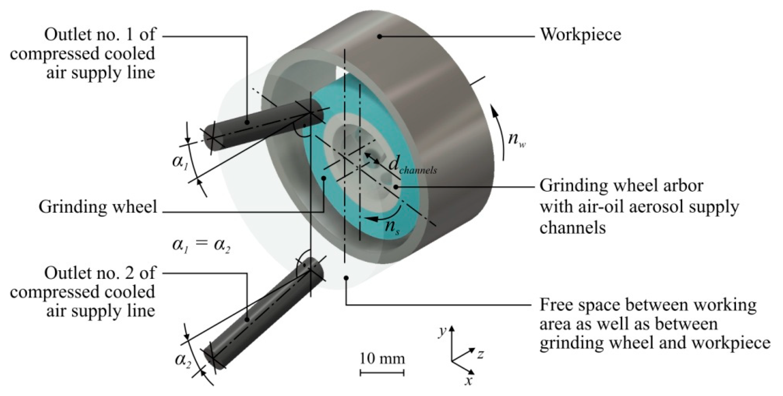
When configuring the components of the cooling system, a CAG nozzle and an air-oil aerosol centrifugal supply system were used (Figure 1), consisting of the following components:
  • six-nozzle omnidirectional minimum quantity lubrication head type ZR-K 360°;
  • MQL head supply system with compressed air and oil from the workpiece spindle side;
  • special design grinding wheel arbor;
  • system for fixing the ZR-K 360° head stationary inside the rotating grinding wheel arbor;
  • special ceramic grinding wheel with dimensions 40 mm × 20 mm × 26 mm adapted to work with hollow grinding arbor;
  • as a lubricant, an oil called Cimtech® MQL from CIMCOOL® Fluid Technology, part of Milacron LLC, was used.
In the immediate surroundings of the machining zone, a CAG nozzle of the type Vortec 610 was placed. This nozzle was equipped with a double-jet flexible supply line. One outlet of the supply line was directed in front of the grinding zone for cooling, while the other outlet was placed directly behind the grinding wheel’s contact zone with the workpiece to support the blowing of machining products. The outlets of the CAG nozzle supply line had openings with a diameter of 6.3 mm. The pressure of the air feeding the nozzle was 0.6 MPa, which made it possible to reduce the temperature of air at the outlet to approximately −5 °C. The total CAG flow rate for such CAG configuration was QCCA = 49.8 dm3/min (0.00083 m3/s).

3. Simulation Tests of Coolant Flow and Heat Transfer in the Grinding Zone

The aim of the simulation studies was to determine the most favourable geometrical and kinematic parameters of the system in question in terms of the flow of cooling and lubricating media (air-oil aerosol and CCA) and heat exchange. The simulation was carried out for a total of 27 system variants, varying:
  • the geometry of the grinding arbor (three variants of arrangement and number of channels on its circumference);
  • the angle of inclination of the outlets of the CCA supply line to the grinding zone (three angle values);
  • the peripheral speed of the grinding wheel vs and workpiece vw (three values of vs and vw speed).
In each variant of the simulation tests, the influence of the input variables on the direction of flow, speed and temperature of coolants, and grinding wheel and workpiece temperature was determined. The results of the different simulation variants made it possible to choose the most advantageous configuration of the tested system, without the necessity of carrying out analogous, real comparative tests. The obtained results of the simulation experiments were used to develop mathematical models of the research object (MMRO) describing the influence of input variables on selected result parameters of the analysed process.

3.1. Methodology of Simulation Tests

During the simulation tests, the following input values related to the model geometry were changed:
  • number of channels in grinding arbor for air-oil aerosol centrifugal delivery: nchannels = 3, 6, 9;
  • the diameter of a single channel in the grinding arbor for air-oil aerosol delivery depended on their number in such a way that the total area of the channels cross-sectional area is constant: dchannels = 5.00 mm (for nchannels = 9); 6.12 mm (for nchannels = 6); 8.66 mm (for nchannels = 3);
  • alignment angle in the z axis of the CCA supply line outlets: α1 = α2 = 10.0°; 12.5°; 15.0°;
and the kinematic parameters of the simulated process:
  • peripheral speed of grinding wheel: vs = 40 m/s; 50 m/s; 60 m/s;
  • peripheral speed of the workpiece (speed ratio q = vs/vw was taken as constant: q = 60): vw = 0.67 m/s, 0.83 m/s, 1.00 m/s.
In the simulation studies, a total of 27 numerical experiments were assumed to be carried out. Every point of the experimental plan was related to a different combination of input variable values. The output variables from the simulation process were: direction and speed of the air-oil aerosol flow, direction and speed of the CCA flow, and the temperature of these two streams. The results of the simulation studies were the temperature distribution in the volume of the grinding wheel and the workpiece. The flow rate of the air-oil aerosol and CCA and other geometrical parameters of the analysed system remained constant. The aim of the study was to determine the most advantageous variant of the combination of input values of the simulation, making it possible to obtain the highest flow velocity of the cooling lubricants and the lowest temperature of the grinding wheel and the workpiece. Selected physical and mechanical properties of the workpiece material (100Cr6 steel) are given in Table 1.
Figure 2 presents an axonometric view of the solid model developed for numerical simulation. The most important geometric and kinematic parameters of the model are also marked.
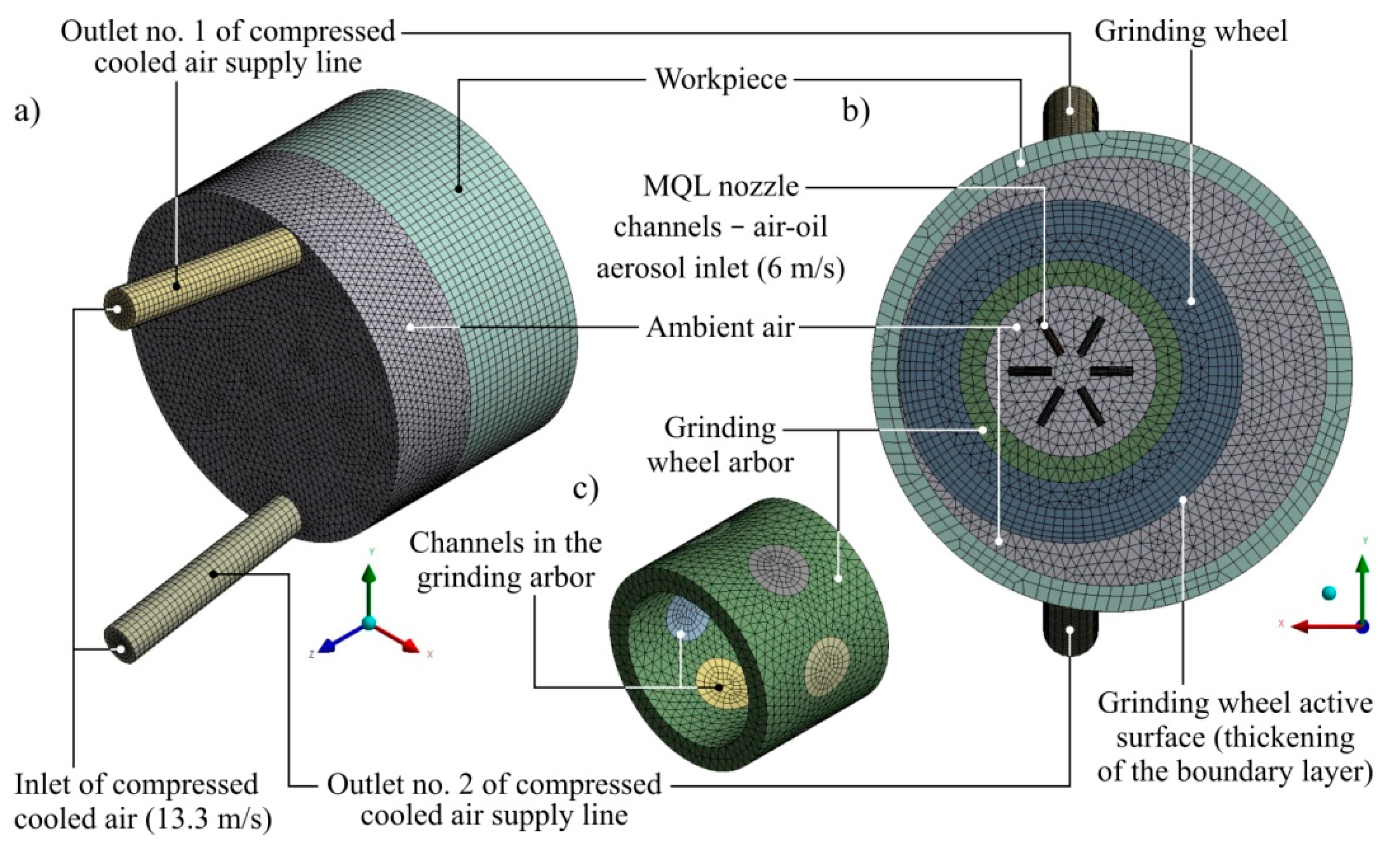
The simulation was conducted with Ansys CFX 18.1 software. In the simulation studies, the Finite Volume Method was used to solve systems of differential equations by dividing (discretisation) the fluid domain and performing calculations for the volume of mesh near nodes of the created elements. The view of individual solids of the considered system after discretisation is given in Figure 3.
The simulation was performed as a steady-state case. The number of iterations was set as 1000. The convergence criteria for each simulation case were residual of Root Mean Square (RMS) type with residua target set to 1 × 10⁻⁴. Each case achieved convergence after about 900 iterations.
The presented case was simulated like a turbulent flow. The two-dimensional k-ω SST model was used. The values of empirical coefficients of the model were set as defaults. Additionally, the blending functions were not considered at this stage of simulation. Model coefficients and blending functions are important in cases of flow with a high degree of tribalisation along with additional elements appearing in the analysis, such as the free surface, like in, among others, D’Ippolito et al. [56]. In the case under consideration, the simulation results reflect the actual state occurring on the surface of the grinding zone. Additional settings for the turbulence model were not required.
Various types of elements and their sizes were used to generate a discrete finite element mesh. Lumps of regular solids (workpiece geometry) and fluids bounded by a cylindrical wall (geometry of the CCA supply line outlets, the channels around the air-oil aerosol supply nozzle, and the channels in the grinding arbor) were divided into cubic discrete elements (hexahedrons). The use of cubic elements made it possible to discredit solids with less complicated geometries with a relatively small number of elements and knots (in relation to the mesh composed of quadriceps), which limited the duration of the simulation calculations. The remaining solids with less complex geometries, structures and predicted flow characteristics (geometry of the grinding wheel, grinding wheel and ambient air geometry) were divided into tetrahedrons, which are more adaptable to complex geometries, but which, however, may result in a greater demand for the calculation power of the workstation. Table 2, Table 3, Table 4 and Table 5 present a complete list of the simulation parameters.
Simulation studies were conducted according to the planned experiment. A complete three-level plan with three variables vs, nchannels, α (with α = α1 = α2) was used. Both the planning of experiments as well as statistical analysis of the obtained simulation results were carried out with the use of specialist software Experiment Planner 1.1, which enables planning of exploratory and proper experiments as well as identification and analysis of the mathematical model of the research object.

3.2. Mathematical Model

The flow of a fluid is described by the conservation of mass (continuity) equation and the conservation of momentum equation, also known as the Navier–Stokes equations.
Equations for the conservation of momentum are derived by applying Newton’s law of motion to a small volume of fluid. Newton’s law states that the rate of change of momentum for a volume of fluid is equal to the sum of all external forces acting on that volume. The equation of velocity balance (1) takes the following form:
ρ u t + ρ u · = [ p + ( μ + μ T ) ( u + ( u ) T ) ] · { [ ρ C d ( 1 C d ) ] u s l i d e u s l i d e } + F ,
where:
  • Cd—mass density of dispersed phase,
  • F—additional volumetric forces,
  • p—pressure,
  • t—time,
  • u—velocity,
  • uslide—velocity in-between phases,
  • μ—dynamic viscosity,
  • μT—turbulent viscosity,
  • ρ—density;
and:
ρ = φ c ρ c + φ d ρ d ,
where:
  • ρc—density of continuous phase,
  • ρd—density of dispersed phase,
  • φc—volumetric share of continuous phase,
  • φd—volumetric share of dispersed phase;
and:
C d = φ d ρ d ρ .
For a continuous fluid (in this case, it is air), viscosity is constant. The left side of the equation represents a temporal variation in momentum and gas acceleration. The right side represents the pressure gradient force (the normal stress) and the viscous force (the tangential shear stress). The equation of continuity (4) for the mixture of the dispersed fluid (oil) and continuous phase (air) is obtained by applying the principle of mass conservation to a small volume of fluid. The standard (general) form for Cartesian coordinates is as follows [57]:
ρ t + · ( ρ u ) = 0 .
The flow of a dispersed phase is represented by the following Equation (5):
φ d t + · φ d [ u + φ d ( 1 C d ) u s l i d e D m d φ d φ d ] = m d c ρ d ,
where:
  • Dmd—diffusion coefficient of dispersed phase in a fluid,
  • mdc—mass transfer between phases.
Because a fluid-gas drag function is used, the Schiller–Neumann model was applied. It is described by the following Equation (6):
3 4 f d d d ρ c | u s l i d e | u s l i d e = ρ ρ d ρ p ,
where:
  • dd—diameter of dispersed phase,
  • fd—coefficient of flow resistance for dispersed phase.
The correct limiting behaviour in the inertial regimes is ensured by the limitation of Reynolds number as follows (7):
f d = { 24 R e p ( 1 + 0.15 R e p 0.687 ) 0.44 f o r   R e p R e p < 1000 > 1000 } ,
where Reynolds number is described by the following equation:
R e p = d d ρ c | u s l i d e | μ .
The heat exchange is described by total energy equation as follows:
( ρ h t o t ) t p t + ( ρ U h t o t ) = ( λ T ) + S E ,
where h t o t —the total enthalpy is described by equation:
h t o t = h + 1 2 U 2 .
An SST model was used for turbulence. This two-equation model is the simplest and the most popular choice for modelling turbulence for similar cases. This is because of the fact that two different transport equations characterise two independent properties of the turbulent flow. Moreover, it is robust, economical, and reasonably accurate for a large variety of turbulent flows [58,59].
Turbulence kinetic energy is described by Equation (11):
ρ k t + ρ u · k = · [ ( μ σ k μ T ) k ] + P k ρ β * k ω ,
where:
  • k—kinetic energy,
  • β, σk—model constants;
and:
P k = μ T ( u : ( u + ( u ) T ) 2 3 ( · u ) 2 ) 2 3 ρ k · u ,
and:
μ T = ρ k ω .
The grade of the dissipation of the energy is described by Equation (14):
ρ ω t + ρ u · ω = · [ ( μ + σ ω μ T ) ω ] + φ ω k P k ρ β ω 2 ,
where:
  • Pk—turbulence production,
  • σω—model constant,
  • ω—turbulent frequency.
The SST model makes it possible to avoid miscalculations of the turbulence by the wall. At minimum values, the Reynolds number is switched over to the wall function. The SST model correctly calculates the turbulence in such cases as sudden stream expansions (like at the end of wheel channel).

3.3. The Results of Simulation Tests and Their Analysis

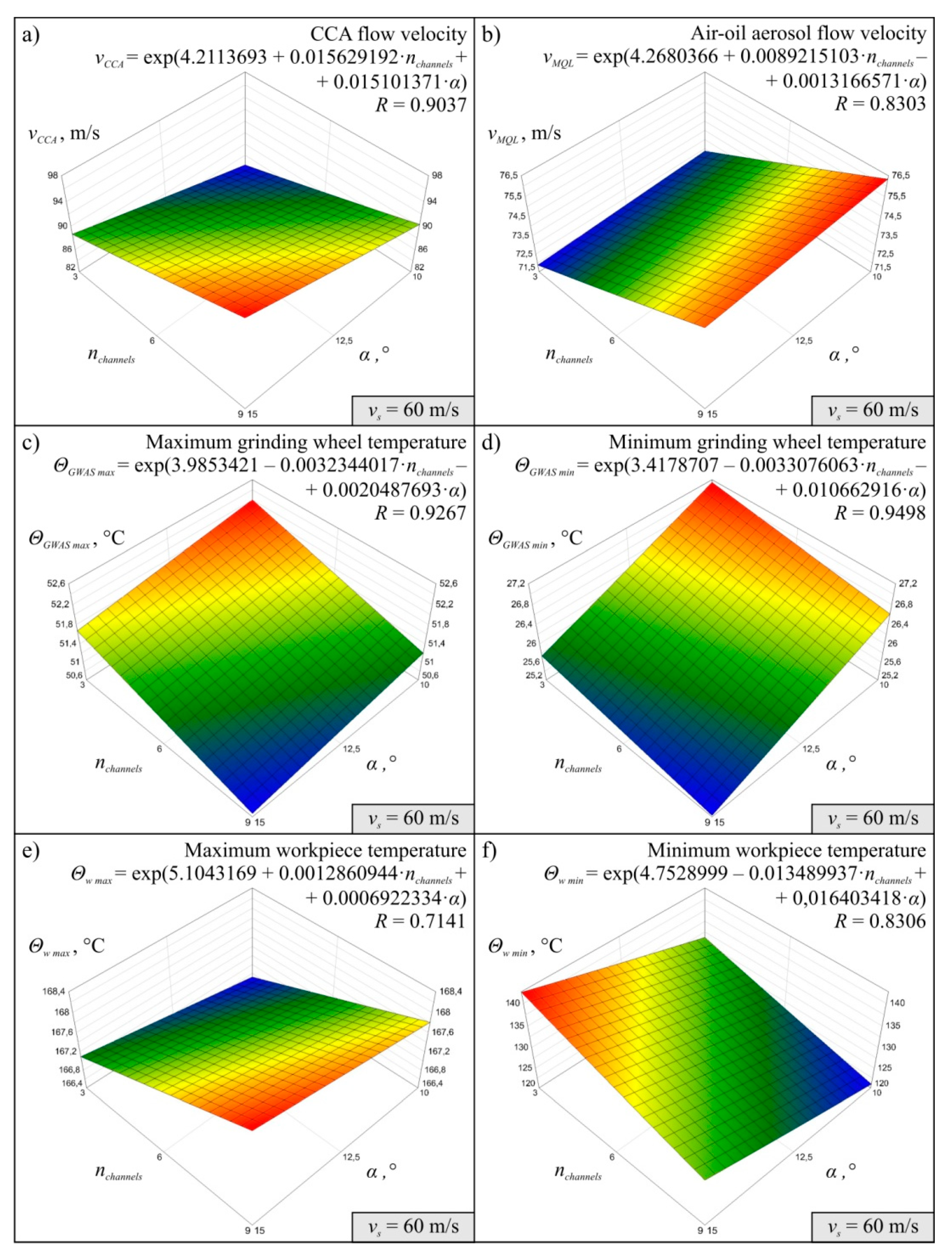
The results obtained for 27 variants of the simulations carried out in accordance with the experimental plan made it possible to determine the MMRO together with the values of the multidimensional correlation coefficient R, which is a measure of model adequacy assessment. It was assumed that MMRO would be described as a first-degree exponential function without interaction. A total of 18 mathematical models of the research object were determined, six for each simulation variant, differing in the value of peripheral wheel speed vs. The models developed describe the effect of change in the number of channels in the grinding arbor nchannels and change in the angle α of inclination of the CCA delivery line outlets on the flow velocity of compressed cooled air vCCA, air-oil aerosol flow velocity vMQL, maximum ΘGWAS max and minimum grinding wheel temperature ΘGWAS min and maximum Θw max and minimum workpiece temperature Θw min in the system under analysis.
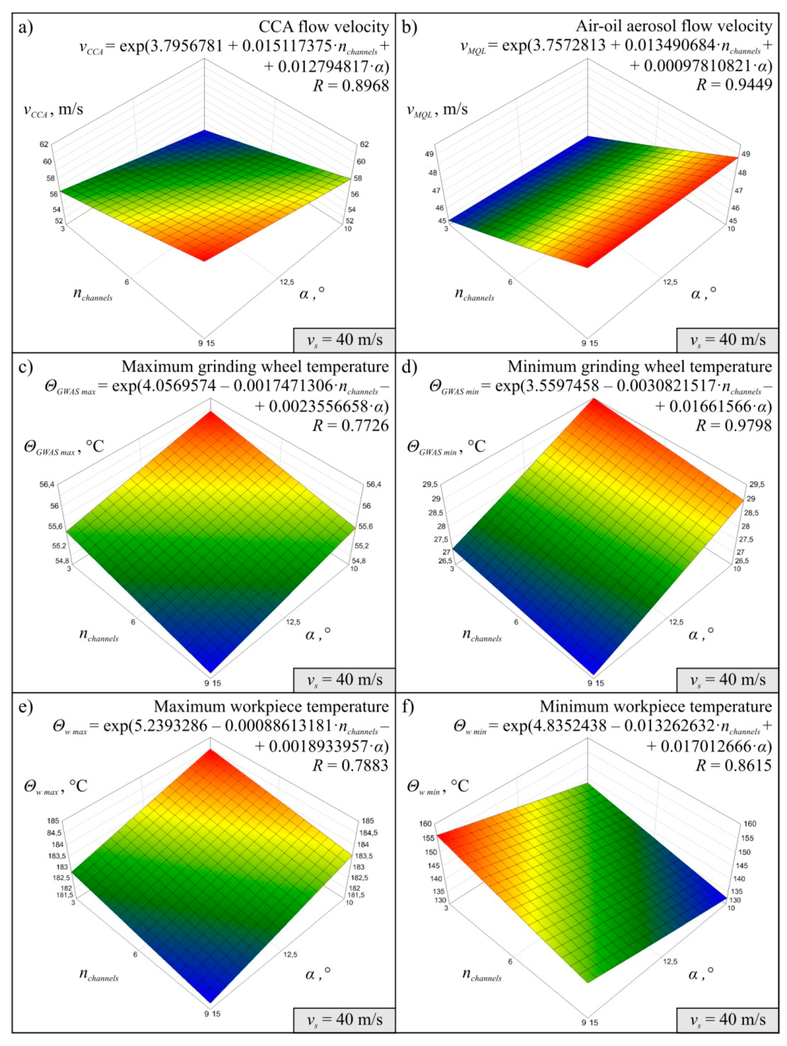
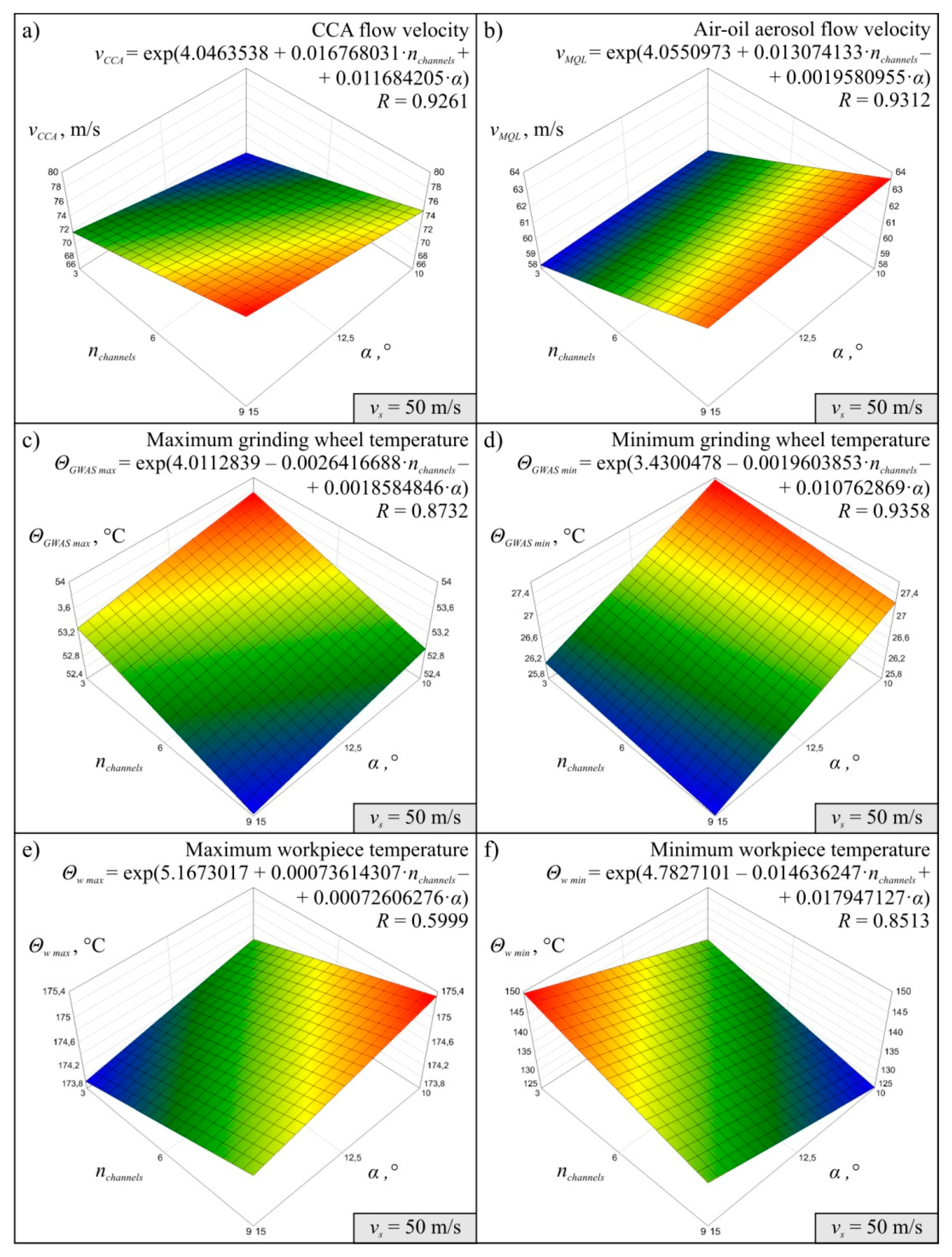
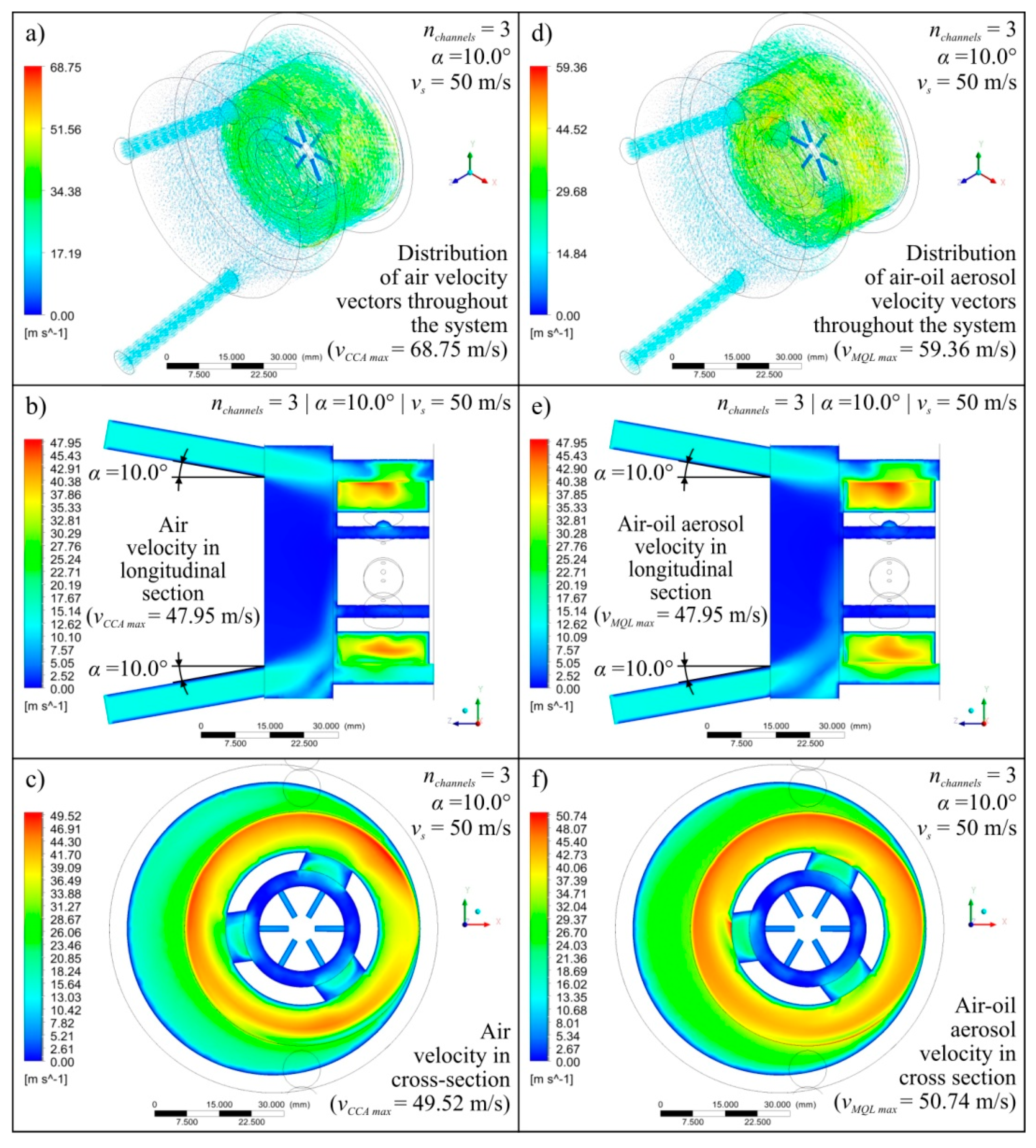
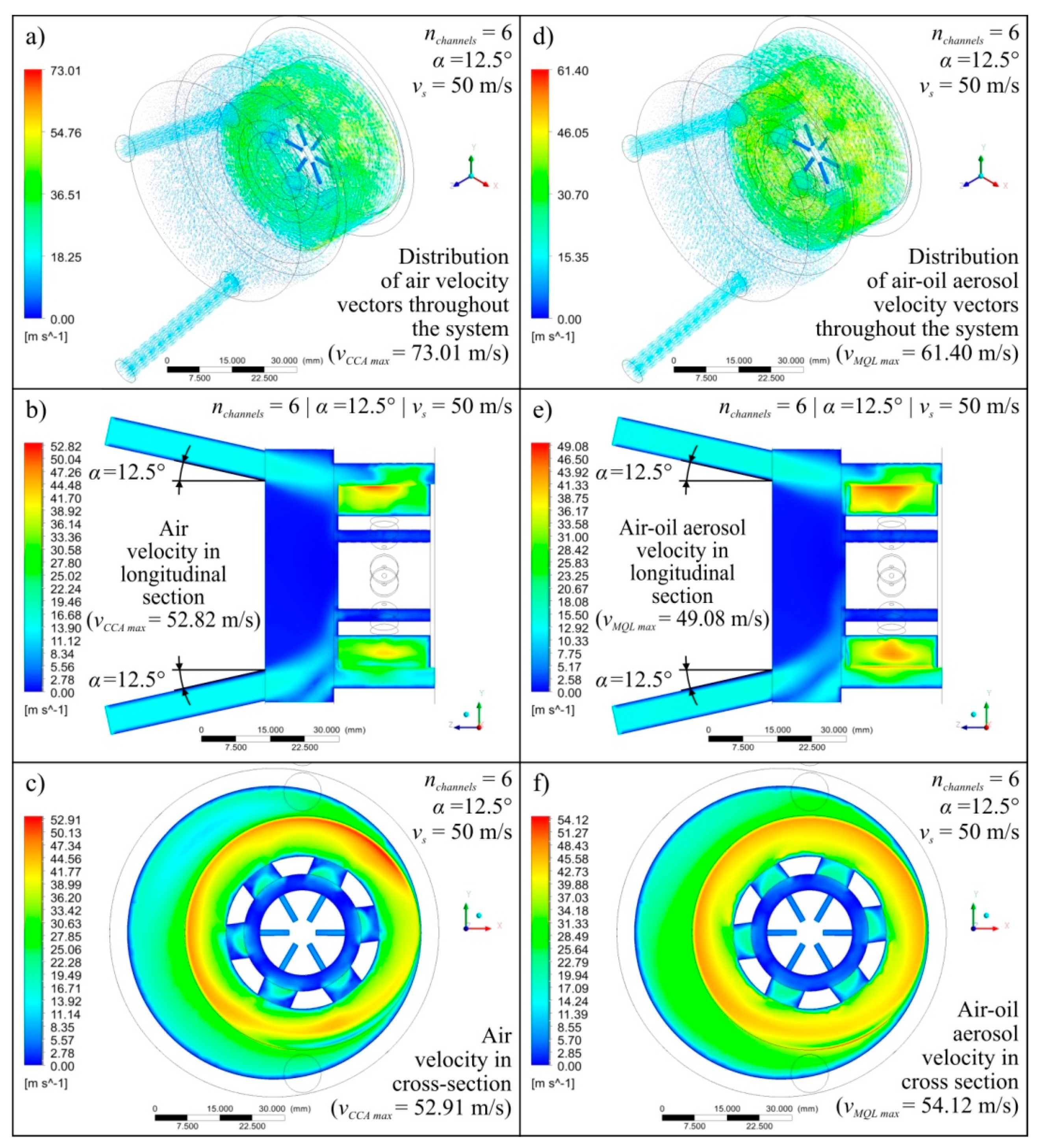
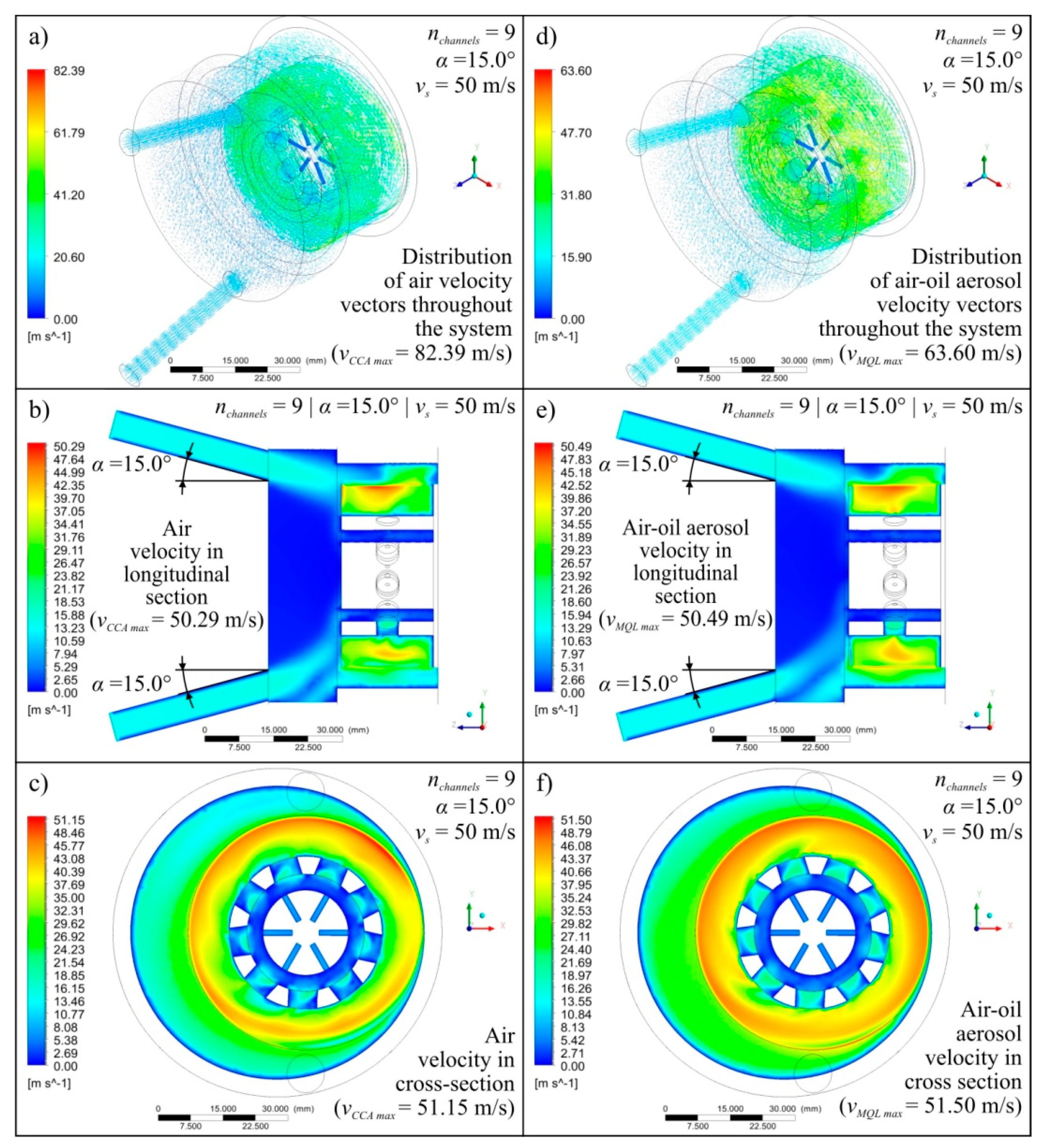
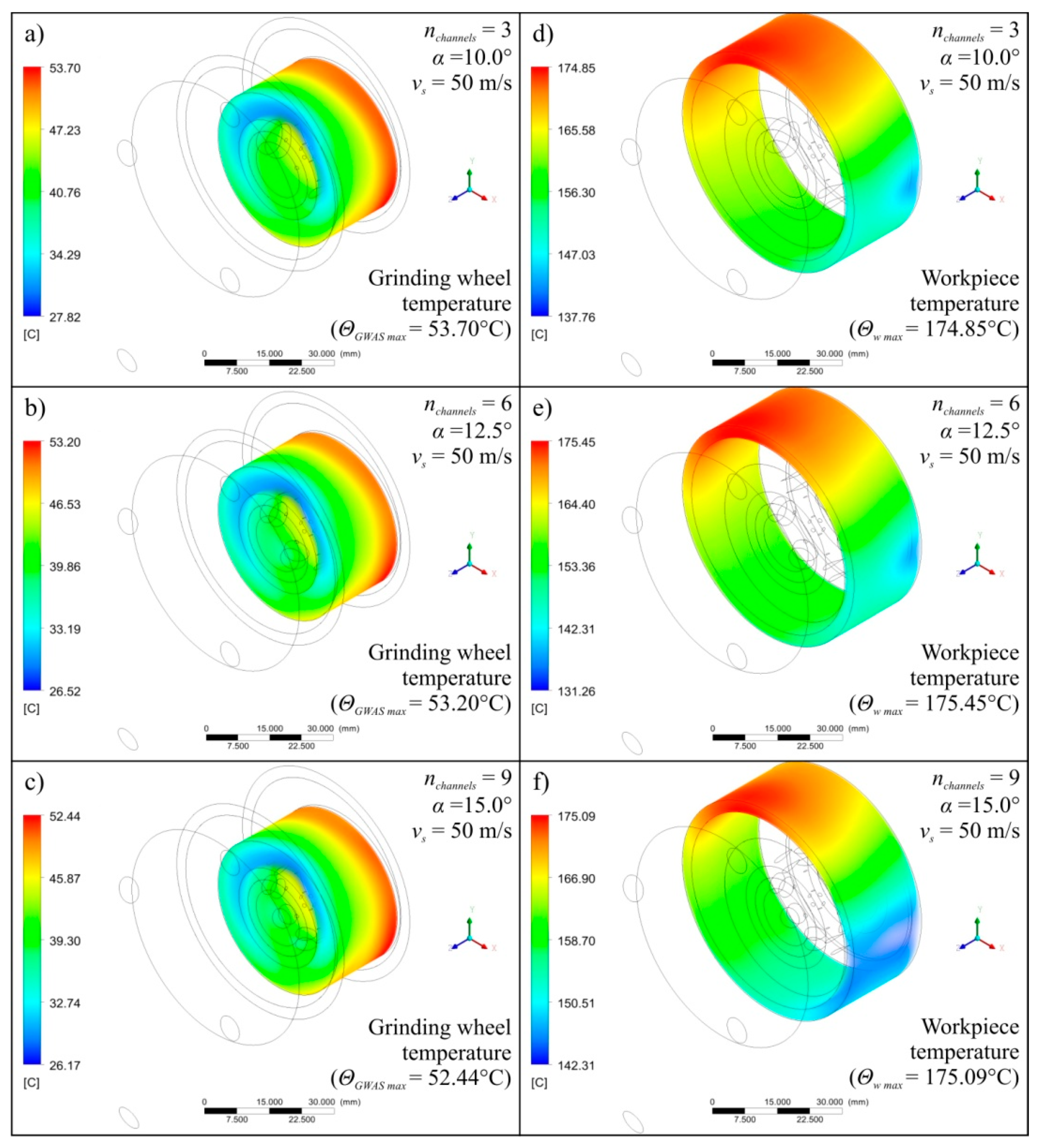
Diagrams showing the variability of the determined mathematical models together with their equations and values of R coeficient were shown in Figure 4 (for vs = 40 m/s), Figure 5 (for vs = 50 m/s), and Figure 6 (for vs = 60 m/s). The following figures show selected detailed simulation results in the form of colour maps of air velocity and air-oil aerosol distribution in the whole system, in longitudinal and cross-sectional sections (Figure 7, Figure 8 and Figure 9), as well as the distribution of grinding wheel and workpiece temperature (Figure 10). These figures present simulation results for three selected variants corresponding to the following combinations of input parameters:
The simulation results proved that both the CCA and air-oil aerosol flow velocity increases as the number of channels in the grinding arbor through which the coolant generated by the MQL nozzle is delivery increases (Figure 4, Figure 5 and Figure 6). The velocity vCCA also increases with increasing the outlet angle value α within the range of its variability tested (Figure 4a, Figure 5a and Figure 6a). However, the angle α does not have a clear effect on the speed value of vMQL describing the movement of the air-oil aerosol delivered by the MQL nozzle centrifugally through the grinding arbor and the grinding wheel to the grinding zone (Figure 4b, Figure 5b and Figure 6b). As the speed of the cooling lubricants (in this case CCA and air-oil aerosol) increases, heat is taken away from the solids (grinding wheel and workpiece) by the flowing gas (air) and liquid (oil). This phenomenon is visible on the diagrams presenting values of ΘGWAS max (Figure 4c, Figure 5c and Figure 6c), ΘGWAS min (Figure 4d, Figure 5d and Figure 6d) and Θw min (Figure 4f, Figure 5f and Figure 6f). It should be noted that the greatest influence of nchannels and α parameters was obtained for minimum values of the workpiece temperature Θw min (Figure 4f, Figure 5f and Figure 6f). The values of the maximum workpiece temperature Θw max (Figure 4e, Figure 5e and Figure 6e) changed least significantly as a function of these parameters (nchannels and α). Such small variability of this resultant factor caused that difficulties with determination of MMRO of high adequacy were encountered and the calculated multidimensional correlation coefficient R assumed relatively small values for these cases: R = 0.7883 (Figure 4e), R = 0.5999 (Figure 5e) and R = 0.7141 (Figure 6e). As a result, the slope of the surface resulting from the regression equation Θw max is different for subsequent variants corresponding to the three values of vs adopted in the study (Figure 4e, Figure 5e and Figure 6e), which does not give the possibility of unambiguous conclusion about the influence of input factors on the analysed parameter. In the case of the remaining MMROs, the values of the R coefficient ranged from R = 0.8303 (Figure 6b) to R = 0.9798 (Figure 4d). Taking into account the stochastic nature of the grinding process, which is characterised by a large number of variables and many interferences, the obtained values of the R coefficient should be considered satisfactory and prove the acceptable adequacy of the models determined.
A more in-depth analysis of the causes of the revealed dependencies was possible based on the results of 27 detailed points of the experimental plan. Figure 7, Figure 8, Figure 9 and Figure 10 show the most important of the analysed simulation results for selected three combinations of input factor values (α, nchannels and vs). Colour maps of changes in velocity of vCCA and vMQL and distribution of their vectors (Figure 7, Figure 8 and Figure 9), as well as maps of temperature distribution of grinding wheel and workpiece (Figure 10), make it possible to trace the path taken by CCA and air-oil aerosol from their delivery points to the grinding zone. The asymmetry in the grinding wheel and workpiece temperature distribution resulting from the direction of the main coolant agent (CCA) delivery in the analysed process is also visible.
The above described trends of change are the same for all three variants of the peripheral speed of grinding wheel applied in simulation tests. Their results showed the expected increase in the flow velocity of the cooling and lubrication media together with the increase in value vs. The simulation tests therefore show that the most favourable conditions (taking into account heat exchange) can be obtained with grinding at a speed of vs = 60 m/s (the highest in the assumed range of variability of this parameter).
The obtained results of the simulation tests made it possible to select the following parameters of the system under consideration as the most favourable ones:
  • number of channels in grinding arbor for air-oil aerosol centrifugal delivery: nchannels = 9;
  • the diameter of a single channel in the grinding arbor for air-oil aerosol centrifugal delivery: dchannels = 5.00 mm;
  • alignment angle in the z axis of the CCA supply line outlets: α1 = α2 = 15.0°;
  • peripheral speed of grinding wheel: vs = 60 m/s;
  • peripheral speed of the workpiece: vw = 1.00 m/s.

4. Conclusions

The results of the numerical simulations described in this article prove that it is possible to achieve a beneficial effect of combining the centrifugal MQL method and CAG nozzle cooling in the internal cylindrical grinding process. Analyses carried out in relation to many criteria of the grinding process evaluation allowed the following conclusions to be drawn.
  • Simulation studies showed that both the number of channels in the grinding arbor nchannels and the angle of inclination of the CAG nozzle outlets α have a significant impact on the coolant flow rate and thermal conditions in the grinding zone.
  • The results of the simulation tests indicate that a larger number of channels in the grinding arbor (from the range under test) has the effect of increasing the maximum coolant flow velocity (air flow velocity and oil flow velocity) in the grinding zone due to a local increase in the oil and air particle flow velocity in the volume of the grinding arbor channels, which was caused by the smaller value of the cross-sectional area of a single channel through which the coolant flowed.
  • Variants of the system with nine channels in the grinding arbor allowed for a noticeable reduction in the temperature of the workpiece, which resulted from a more even distribution of the air-oil aerosol on the perimeter of the inner cylindrical surface of the workpiece domain, in relation to variants with six and three channels in the grinding arbor.
  • The 15° angle of inclination of the CAG supply line outlets affects the concentration of the greater part of the high-speed CCA jet on the surface of the grinding wheel, which enables increased cooling efficiency. The 10° inclination of the CAG supply line outlets affects the concentration of the greater part of the CCA jet on the workpiece surface, which enables an increased efficiency of workpiece cooling.
  • As the peripheral speed of the grinding wheel domain increased (in the examined range), the maximum flow speed of the coolant in the grinding zone and the cooling efficiency of both the grinding wheel domain and the workpiece increased.
  • The lower speed of the air-oil aerosol flow through the intergranular spaces translates into less effective heat removal from the grinding wheel body.
  • The results obtained for the simulation tests made it possible to visualise the velocity vectors of the two-phase coolant flow in a complex system of centrifugal air-oil aerosol delivery through an open structure of a very fast rotating porous layer (grinding wheel), with an additional CCA supply using an external CAG nozzle, which is an important cognitive aspect and allows for further development of research in this field.
  • The simulation tests carried out enabled a precise selection of the conditions for delivery the coolant to the grinding zone for further experimental testing of the analysed internal cylindrical grinding process. The results of experimental research are described in detail in the paper [60]. They confirm that with the application of the most advantageous process conditions resulting from the simulation tests it is possible to achieve effective penetration of cooling and lubricating agents into the grinding zone. Moreover, it was proved that directing the CCA stream directly behind the grinding wheel’s contact zone with the machined material effectively cleans the working area from chips, thus limiting the phenomenon of clogging of the GWAS.

Author Contributions

Conceptualisation, S.K. and K.N.; methodology, S.K. and M.J.; software, S.K. and M.J.; validation, S.K., K.N. and M.J.; writing, S.K., K.N. and M.J.; supervision, M.J. and K.N. All authors have read and agreed to the published version of the manuscript.

Funding

This research received no external funding.

Conflicts of Interest

The authors declare no conflict of interest.

Nomenclature

Symbols
aeworking engagement (machining allowance), mm
Achannelssummary cross-sectional area of the channels in the grinding arbor, mm2
Cdmass density of dispersed phase, kg/m
dchannelsgrinding arbor channels diameter, mm
dsgrinding wheel outer diameter, mm
dwworkpiece internal diameter, mm
Dmddiffusion coefficient of dispersed phase in a fluid, m/s2
Fadditional volumetric forces, N/kg
fdcoefficient of flow resistance for dispersed phase
Ggrinding ratio
mdcmass transfer between phases
nchannelsnumber of channels in the grinding arbor
nsgrinding wheel rotational speed, rpm
nwworkpiece rotational speed, rpm
ppressure, Pa
Pkturbulence production
qspeed ratio q = vs/vw
QCCAcompressed cold air flow rate, dm3/min
Rmultidimensional correlation coefficient
RGWASroughnes of the grinding wheel active surface
ttime, s
Ttemperature, °C
TGWAStemperature of the heat source on the external surface of the grinding wheel, °C
Twtemperature of the heat source on the internal surface of the workpiece, °C
uvelocity, m/s
Uwork, J
uslidevelocity in-between phases, m/s
uτfriction velocity, m/s
vcvolume of continuous phase, m3
vCCAcompressed cooled air flow rate, m/s
vdvolume of dispersed phase, m3
vfoaxial feed velocity of the grinding wheel, mm/s
vfrradial feed velocity of the grinding wheel, mm/s
vMQLair-oil aerosol flow rate, m/s
vsgrinding wheel peripheral speed, mm/s
vwworkpiece peripheral speed, mm/s
Greek symbols
α1alignment angle of compressed cooled air supply line outlet no. 1, °
α2alignment angle of compressed cooled air supply line outlet no. 2, °
βmodel constant
εdissipation rate of turbulent energy
ΘGWAS maxmaximum grinding wheel temperature, °C
ΘGWAS minminimum grinding wheel temperature, °C
Θw maxmaximum workpiece temperature, °C
Θw minminimum workpiece temperature, °C
μdynamic viscosity, Pa·s
μTturbulent viscosity, Pa·s
νkinematic viscosity, m2/s
ρdensity, kg/m3
ρcdensity of continuous phase, kg/m3
ρddensity of dispersed phase, kg/m3
σkmodel constant
σωmodel constant
φcvolumetric share of continuous phase
φdvolumetric share of dispersed phase
ωturbulent frequency
Acronyms
CAG Cold Air Gun
CAMQL Cold Air Minimum Quantity Lubrication
CAOM Cold Air and Oil Mist
CCA Compressed Cooled Air
CFD Computational Fluid Dynamics
GWAS Grinding Wheel Active Surface
MMRO Mathematical Model of the Research Object
MQC Minimum Quantity Cooling
MQCL Minimum Quantity Cooling Lubrication
MQL Minimum Quantity Lubrication

References

  1. Marinescu, I.D.; Hitchiner, M.; Uhlmann, E.; Rowe, W.B.; Inasaki, I. Handbook of Machining with Grinding Wheels; CRC Press: Boca Raton, FL, USA, 2007. [Google Scholar]
  2. Marinescu, I.; Rowe, W.B.; Dimitrov, A.B.; Inasaki, I.; Dimitrov, B. Tribology of abrasive machining processes. J. Manuf. Sci. Eng. 2004, 126, 859. [Google Scholar] [CrossRef] [Green Version]
  3. Jackson, M.J.; Davim, J.P. Machining with Abrasives; Springer: New York, NY, USA, 2010. [Google Scholar]
  4. Klocke, F. Manufacturing Processes 2, Grinding, Honing, Lapping; Springer: Berlin/Heidelberg, Germany, 2009. [Google Scholar]
  5. Kapłonek, W.; Nadolny, K. The diagnostics of abrasive tools after internal cylindrical grinding of hard-to-cut materials by means of a laser technique using imaging and analysis of scattered light. Arab. J. Sci. Eng. 2012, 38, 953–970. [Google Scholar] [CrossRef] [Green Version]
  6. Kapłonek, W.; Nadolny, K.; Hloch, S. The use of opto-digital microscope for analysis Of the PFA-based abrasive tools with surface micro-discontinuities. Niger. J. Technol. 2014, 33, 125. [Google Scholar] [CrossRef] [Green Version]
  7. Nadolny, K. Micro-discontinuities of the grinding wheel and their effects on its durability during internal cylindrical grinding. Mach. Sci. Technol. 2013, 17, 74–92. [Google Scholar] [CrossRef]
  8. Nadolny, K.; Habrat, W. Potential for improving efficiency of the internal cylindrical grinding process by modification of the grinding wheel structure—Part I: Grinding wheels made of conventional abrasive grains. Proc. Inst. Mech. Eng. Part E J. Process. Mech. Eng. 2016, 231, 621–632. [Google Scholar] [CrossRef]
  9. Nadolny, K.; Habrat, W. Potential for improving efficiency of the internal cylindrical grinding process by modification of the grinding wheel structure: Part II: Grinding wheels made of superabrasive grains. Proc. Inst. Mech. Eng. Part E J. Process. Mech. Eng. 2016, 231, 813–823. [Google Scholar] [CrossRef]
  10. Nadolny, K.; Kapłonek, W.; Ungureanu, N. Effect of macro-geometry of the grinding wheel active surface on traverse internal cylindrical grinding process. J. Mech. Energy Eng. 2017, 1, 15–22. [Google Scholar]
  11. Nadolny, K.; Al-Obaidi, A.S.M. A multi-criteria methodology for effectiveness assessment of internal cylindrical grinding process with modified grinding wheels. Int. J. Adv. Manuf. Technol. 2016, 87, 625–637. [Google Scholar] [CrossRef] [Green Version]
  12. Wójcik, R.; Nadolny, K. The effect of the grinding wheel modification on the state of the workpiece surface layer after internal cylindrical grinding of steel C45. Proc. Inst. Mech. Eng. Part E J. Process. Mech. Eng. 2016, 231, 1162–1173. [Google Scholar] [CrossRef]
  13. Astakhov, V.P. Tribology of Metal Cutting; Elsevier: Oxford, UK, 2006. [Google Scholar]
  14. Klocke, F. Manufacturing Processes 1; Springer Science and Business Media LLC: Berlin/Heidelberg, Germany, 2011. [Google Scholar]
  15. Davim, J.P. Machining: Fundamentals and Recent Advances; Springer: London, UK, 2008; pp. 195–223. [Google Scholar]
  16. Hadad, M. An experimental investigation of the effects of machining parameters on environmentally friendly grinding process. J. Clean. Prod. 2015, 108, 217–231. [Google Scholar] [CrossRef]
  17. Bianchi, E.C.; Rodriguez, R.L.; Hildebrandt, R.A.; Lopes, J.C.; De Melo, H.J.; Da Silva, R.B.; De Aguiar, P.R. Plunge cylindrical grinding with the minimum quantity lubrication coolant technique assisted with wheel cleaning system. Int. J. Adv. Manuf. Technol. 2017, 95, 2907–2916. [Google Scholar] [CrossRef] [Green Version]
  18. Bianchi, E.C.; Sato, B.K.; Sales, A.R.; Lopes, J.C.; De Melo, H.J.; Sanchez, L.E.D.A.; Diniz, A.E.; Aguiar, P.R. Evaluating the effect of the compressed air wheel cleaning in grinding the AISI 4340 steel with CBN and MQL with water. Int. J. Adv. Manuf. Technol. 2017, 95, 2855–2864. [Google Scholar] [CrossRef] [Green Version]
  19. Hadad, M.; Sharbati, A. Thermal aspects of environmentally friendly-mql grinding process. Procedia CIRP 2016, 40, 509–515. [Google Scholar] [CrossRef] [Green Version]
  20. Huang, X.; Ren, Y.; Jiang, W.; He, Z.; Deng, Z. Investigation on grind-hardening annealed AISI5140 steel with minimal quantity lubrication. Int. J. Adv. Manuf. Technol. 2016, 89, 1069–1077. [Google Scholar] [CrossRef]
  21. Morgan, M.; Barczak, L.M.; Batako, A.D. Temperatures in fine grinding with minimum quantity lubrication (MQL). Int. J. Adv. Manuf. Technol. 2011, 60, 951–958. [Google Scholar] [CrossRef]
  22. Da Silva, L.R.; Bianchi, E.C.; Catai, R.E.; Fusse, R.Y.; França, T.V.; Aguiar, P.R. Study on the behavior of the minimum quantity lubricant—MQL technique under different lubricating and cooling conditions when grinding ABNT 4340 steel. J. Braz. Soc. Mech. Sci. Eng. 2005, 27, 192–199. [Google Scholar] [CrossRef]
  23. Silva, L.R.; Bianchi, E.C.; Fusse, R.Y.; Catai, R.E.; Franca, T.V.; Aguiar, P.R. Analysis of surface integrity for minimum quantity lubricant—MQL in grinding. Int. J. Mach. Tools and Manuf. 2007, 47, 412–418. [Google Scholar] [CrossRef]
  24. Tawakoli, T.; Hadad, M.J.; Sadeghi, M.H. Influence of oil mist parameters on minimum quantity lubrication—MQL grinding process. Int. J. Mach. Tools Manuf. 2010, 50, 521–531. [Google Scholar] [CrossRef]
  25. Tawakoli, T.; Hadad, M.; Sadeghi, M.H. Investigation on minimum quantity lubricant-MQL grinding of 100Cr6 hardened steel using different abrasive and coolant–lubricant types. Int. J. Mach. Tools Manuf. 2010, 50, 698–708. [Google Scholar] [CrossRef]
  26. Tawakoli, T.; Hadad, M.; Sadeghi, M.H.; Daneshi, A.; Sadeghi, B. Minimum quantity lubrication in grinding: Effects of abrasive and coolant–lubricant types. J. Clean. Prod. 2011, 19, 2088–2099. [Google Scholar] [CrossRef]
  27. Zhang, Y.; Li, C.; Jia, D.; Zhang, D.; Zhang, X. Experimental evaluation of MoS2 nanoparticles in jet MQL grinding with different types of vegetable oil as base oil. J. Clean. Prod. 2015, 87, 930–940. [Google Scholar] [CrossRef]
  28. Zhang, D.; Li, C.; Zhang, Y.; Jia, D.; Zhang, X. Experimental research on the energy ratio coefficient and specific grinding energy in nanoparticle jet MQL grinding. Int. J. Adv. Manuf. Technol. 2015, 78, 1275–1288. [Google Scholar] [CrossRef]
  29. Barczak, L.; Batako, A.D.; Morgan, M. A study of plane surface grinding under minimum quantity lubrication (MQL) conditions. Int. J. Mach. Tools Manuf. 2010, 50, 977–985. [Google Scholar] [CrossRef]
  30. Chakule, R.R.; Chaudhari, S.S.; Talmale, P.S. Evaluation of the effects of machining parameters on MQL based surface grinding process using response surface methodology. J. Mech. Sci. Technol. 2017, 31, 3907–3916. [Google Scholar] [CrossRef]
  31. Rabiei, F.; Rahimi, A.; Hadad, M.; Ashrafijou, M. Performance improvement of minimum quantity lubrication (MQL) technique in surface grinding by modeling and optimization. J. Clean. Prod. 2015, 86, 447–460. [Google Scholar] [CrossRef]
  32. Sadeghi, M.H.; Hadad, M.J.; Tawakoli, T.; Vesali, A.; Emami, M. An investigation on surface grinding of AISI 4140 hardened steel using minimum quantity lubrication-MQL technique. Int. J. Mater. Form. 2010, 3, 241–251. [Google Scholar] [CrossRef]
  33. Batako, A.D.; Tsiakoumis, V. An experimental investigation into resonance dry grinding of hardened steel and nickel alloys with element of MQL. Int. J. Adv. Manuf. Technol. 2014, 77, 27–41. [Google Scholar] [CrossRef]
  34. Hadad, M.; Hadi, M. An investigation on surface grinding of hardened stainless steel S34700 and aluminum alloy AA6061 using minimum quantity of lubrication (MQL) technique. Int. J. Adv. Manuf. Technol. 2013, 68, 2145–2158. [Google Scholar] [CrossRef]
  35. Sadeghi, M.H.; Haddad, M.J.; Tawakoli, T.; Emami, M. Minimal quantity lubrication-MQL in grinding of Ti–6Al–4V titanium alloy. Int. J. Adv. Manuf. Technol. 2008, 44, 487–500. [Google Scholar] [CrossRef]
  36. Wójcik, R.; Nadolny, K. The effects of a variety of cutting fluids administered using the minimum quantity lubrication (MQL) method on the surface grinding process for nickel-based alloys. J. Zhejiang Univ. 2017, 18, 728–740. [Google Scholar] [CrossRef]
  37. Klocke, F.; Gerschwiler, K. Minimalmengenschmierung–Systeme, Medien, Einsatzbeispiele und okonomische Aspekte der Trockenbearbeitung, Trocken-bearbeitung von Metallen. In Proceedings of the VDI-Seminar, Stuttgart, Germany, 18–18 March 2003; pp. 2.1–2.20. [Google Scholar]
  38. Priarone, P.C.; Robiglio, M.; Settineri, L.; Tebaldo, V. Effectiveness of minimizing cutting fluid use when turning difficult-to-cut alloys. Procedia CIRP 2015, 29, 341–346. [Google Scholar] [CrossRef]
  39. Weinert, K.; Inasaki, I.; Sutherland, J.; Wakabayashi, T. Dry machining and minimum quantity lubrication. CIRP Ann. 2004, 53, 511–537. [Google Scholar] [CrossRef]
  40. Ayoama, T. Development of a mixture supply system for machining with minimal quantity lubrication. Ann. CIRP 2002, 51, 289–292. [Google Scholar] [CrossRef]
  41. Chandrasekaran, H.; Thuvander, A. Modelling tool stresses and temperature. Evaluation in turning using FEM. Mach. Sci. Technol. 1998, 2, 355–367. [Google Scholar] [CrossRef]
  42. Machado, A.R.; Wallbank, J. The effect of extremely low lubricant volumes in machining. Wear 1997, 210, 76–82. [Google Scholar] [CrossRef]
  43. Zhang, S.; Li, J.; Wang, Y. Tool life and cutting forces in end milling Inconel 718 under dry and minimum quantity cooling lubrication cutting conditions. J. Clean. Prod. 2012, 32, 81–87. [Google Scholar] [CrossRef]
  44. Maruda, R.W.; Feldshtein, E.; Legutko, S.; Krolczyk, G.M. Analysis of contact phenomena and heat exchange in the cutting zone under minimum quantity cooling lubrication conditions. Arab. J. Sci. Eng. 2015, 41, 661–668. [Google Scholar] [CrossRef] [Green Version]
  45. Maruda, R.W.; Krolczyk, G.M.; Feldshtein, E.; Pusavec, F.; Szydlowski, M.; Legutko, S.; Sobczak-Kupiec, A. A study on droplets sizes, their distribution and heat exchange for minimum quantity cooling lubrication (MQCL). Int. J. Mach. Tools Manuf. 2016, 100, 81–92. [Google Scholar] [CrossRef]
  46. Maruda, R.W.; Krolczyk, G.M.; Michalski, M.; Nieslony, P.; Wojciechowski, S. Structural and microhardness changes after turning of the aisi 1045 steel for minimum quantity cooling lubrication. J. Mater. Eng. Perform. 2016, 26, 431–438. [Google Scholar] [CrossRef] [Green Version]
  47. Maruda, R.W.; Legutko, S.; Krolczyk, G.M.; Raos, P. Influence of cooling conditions on the machining process under MQCL and MQL conditions. Teh. Vjesn. Tech. Gaz. 2015, 22, 965–970. [Google Scholar] [CrossRef] [Green Version]
  48. Hadad, M.; Tawakoli, T.; Sadeghi, M.H.; Sadeghi, B. Temperature and energy partition in minimum quantity lubrication-MQL grinding process. Int. J. Mach. Tools Manuf. 2012, 54, 10–17. [Google Scholar] [CrossRef]
  49. Saberi, A.; Rahimi, A.; Parsa, H.; Ashrafijou, M.; Rabiei, F. Improvement of surface grinding process performance of CK45 soft steel by minimum quantity lubrication (MQL) technique using compressed cold air jet from vortex tube. J. Clean. Prod. 2016, 131, 728–738. [Google Scholar] [CrossRef]
  50. Choi, H.Z.; Lee, S.-W.; Jeong, H.D. The cooling effects of compressed cold air in cylindrical grinding with alumina and CBN wheels. J. Mater. Process. Technol. 2002, 127, 155–158. [Google Scholar] [CrossRef]
  51. Nguyen, T.; Zhang, L. An assessment of the applicability of cold air and oil mist in surface grinding. J. Mater. Process. Technol. 2003, 140, 224–230. [Google Scholar] [CrossRef]
  52. Stachurski, W.; Nadolny, K. Influence of the condition of the surface layer of a hob cutter sharpened using the MQL-CCA hybrid method of coolant provision on its operational wear. Int. J. Adv. Manuf. Technol. 2018, 98, 2185–2200. [Google Scholar] [CrossRef] [Green Version]
  53. Stachurski, W.; Sawicki, J.; Wójcik, R.; Nadolny, K. Influence of application of hybrid MQL-CCA method of applying coolant during hob cutter sharpening on cutting blade surface condition. J. Clean. Prod. 2018, 171, 892–910. [Google Scholar] [CrossRef]
  54. Yui, A.; Terashima, M.; Wang, J.; Scott, W.; Zhang, L. Abrasive Technology; World Scientific Pub Co. Pte Lt: Singapore, 1999; pp. 394–399. [Google Scholar]
  55. Kieraś, S.; Nadolny, K. Overview of the centrifugal methods of provision the grinding fluid to the grinding zone. J. Mech. Energy Eng. 2017, 1, 7–14. [Google Scholar]
  56. D’Ippolito, A.; Lauria, A.; Alfonsi, G.; Calomino, F. Investigation of flow resistance exerted by rigid emergent vegetation in open channel. Acta Geophys. 2019, 67, 971–986. [Google Scholar] [CrossRef]
  57. Misra, A.; Bonamy, C.; De Souza, L.M.; Hohl, L.; Illner, M.; Kraume, M.; Repke, J.-U.; Thévenin, D. A multi-fluid approach to simulate separation of liquid-liquid systems in a gravity settler. Softw. Archit. Tools Comput. Aided Process. Eng. 2018, 43, 31–36. [Google Scholar] [CrossRef]
  58. Jakubowski, M.; Sterczyńska, M.; Matysko, R.; Poreda, A. Simulation and experimental research on the flow inside a whirlpool separator. J. Food Eng. 2014, 133, 9–15. [Google Scholar] [CrossRef]
  59. Zhang, J.; Fu, S. An efficient approach for quantifying parameter uncertainty in the SST turbulence model. Comput. Fluids 2019, 181, 173–187. [Google Scholar] [CrossRef]
  60. Nadolny, K.; Kieraś, S. Experimental studies on the centrifugal mql-cca method of applying coolant during the internal cylindrical grinding process. Material 2020, 13, 2383. [Google Scholar] [CrossRef] [PubMed]
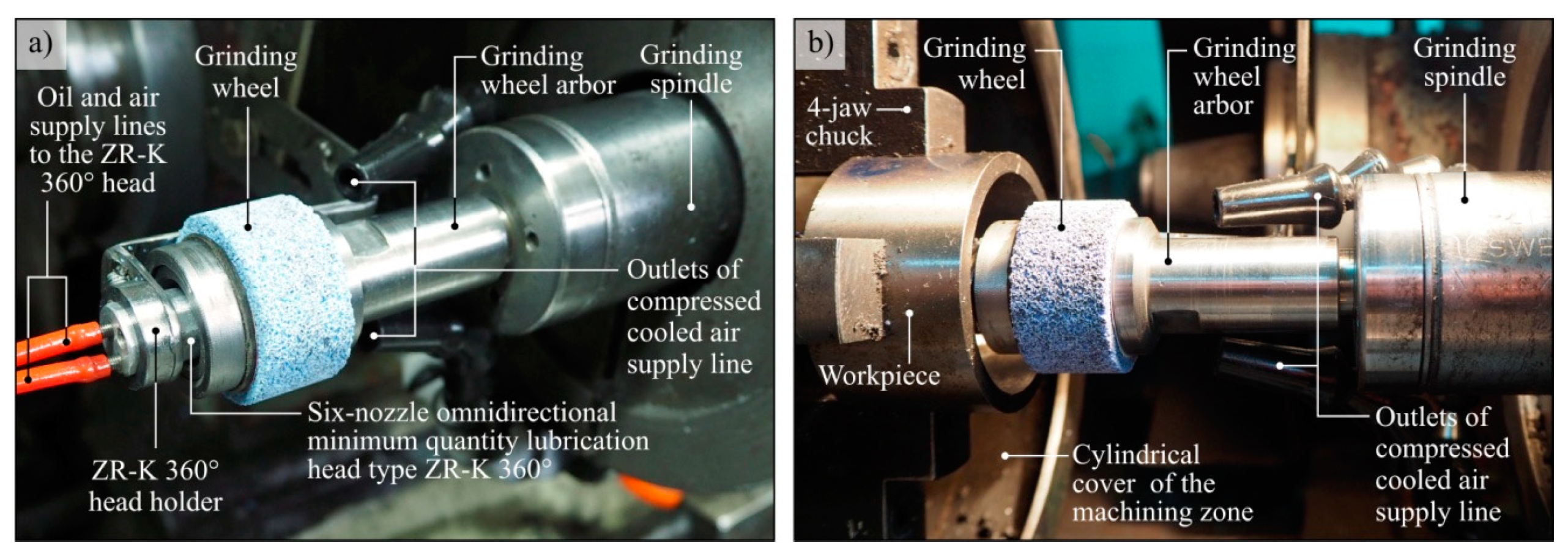
Figure 1. View of centrifugal MQL-CCA method components (a) installed in the grinding zone (b).
Materials 13 02506 g001
Figure 2. Geometrical model for simulation tests with main kinematic and geometric parameters: α1 and α2—alignment angle of compressed cooled air supply line outlet no. 1 and 2; dchannels—grinding arbor channels diameter; ns—grinding wheel rotational speed; nw—workpiece rotational speed.
Materials 13 02506 g002
Figure 3. View of the simulation model solids after discretisation: (a) isometric view of all elements of the model; (b) view of all elements of the model in the xy plane; (c) isometric view of the grinding arbor model.
Materials 13 02506 g003
Figure 4. Mathematical models determined on the basis of simulation results for vs = 40 m/s: (a) vCCA; (b) vMQL; (c) ΘGWAS max; (d) ΘGWAS min; (e) Θw max, (f) Θw min.
Materials 13 02506 g004
Figure 5. Mathematical models determined on the basis of simulation results for vs = 50 m/s: (a) vCCA; (b) vMQL; (c) ΘGWAS max; (d) ΘGWAS min; (e) Θw max, (f) Θw min.
Materials 13 02506 g005
Figure 6. Mathematical models determined on the basis of simulation results for vs = 60 m/s: (a) vCCA; (b) vMQL; (c) ΘGWAS max; (d) ΘGWAS min; (e) Θw max, (f) Θw min.
Materials 13 02506 g006
Figure 7. Exemplary simulation results for α = 10.0°, nchannels = 3 and vs = 50 m/s presented as colour maps of air flow velocity (ac) as well as oil mist flow velocity (df) in the entire system (a,d), in longitudinal section (b,e) and in cross-section (c,f).
Materials 13 02506 g007
Figure 8. Exemplary simulation results for α = 12.5°, nchannels = 6 and vs = 50 m/s presented as colour maps of air flow velocity (ac) as well as oil mist flow velocity (df) in the entire system (a,d), in longitudinal section (b,e) and in cross-section (c,f).
Materials 13 02506 g008
Figure 9. Exemplary simulation results for α = 15.0°, nchannels = 9 and vs = 50 m/s presented as colour maps of air flow velocity (ac) as well as oil mist flow velocity (df) in the entire system (a,d), in longitudinal section (b,e) and in cross-section (c,f).
Materials 13 02506 g009
Figure 10. Exemplary simulation results presented as colour maps of grinding wheel temperature (ac) as well as oil mist flow velocity (df) for α = 10.0°, nchannels = 3, vs = 50 m/s (a,d), for α = 12.5°, nchannels = 6, vs = 50 m/s (b,e) and for α = 15.0°, nchannels = 9, vs = 50 m/s (c,f).
Materials 13 02506 g010
Table 1. Selected physical and mechanical properties of 100Cr6 steel.
Group of ProsperitiesPropertyUnitValue
PhysicalPoisson numberv0.30 (2)
Specific heatJ/kg·K475 (1)
Densitykg/dm37.81
Thermal conductivityW/m·K46.6
Electrical resistivityΩ·mm2/m0.22
Electrical conductivityS·mm2/m4.55
MechanicalThermal expansion10−6·1/K11.4 (1)
Modulus of elasticitylongitudinal GPa210 (2)
tangential GPa80 (2)
Bulk modulusGPa140 (2)
Poisson numberv0.30 (2)
(1) Value calculated for the temperature 20–100 °C; (2) Value calculated for the temperature of 20 °C.
Table 2. Assumptions of simulation.
AssumptionsTotal channel cross-sectional area in the grinding arbor Achannels = 176.7 mm2 for each of the geometrical variants under consideration
Grinding wheel offset from the workpiece surface by 0.2 mm
The GWAS and the face of the grinding wheel are rough (RSGR = 0.425 mm)
Only the main rotational movement of the grinding wheel and the basic feed movement (counter-rotation) of the workpiece are taken into account
No impact of the environment on airflow and flow of air-oil aerosol
The air has the properties of an excellent gas
The air and air-oil aerosol mass is relatively low
The heat exchange takes place through forced convection and heat conduction
On the basis of exploratory thermovision measurements it is assumed that the heat source is the external surface of the grinding wheel (TGWAS = 80 °C) and the internal surface of the workpiece (Tw = 180 °C)
The walls of the CCA supply line outlets and MQL nozzle outlets are insulated
The grinding wheel material is Al2O3 with a porous structure
Values vs were changed at the same time from vw with a constant value of the ratio q = vs/vw = 60
Table 3. Simplifications of simulation.
SimplificationsThe number of geometric simulation variants has been limited
Friction and contact issues between the GWAS and the workpiece surface are omitted
All other walls are modelled as smooth
Axial wheel feed vfa and radial wheel feed vfr have been omitted in order to simplify the system kinematics and shorten the time of simulation calculations
Only the volume of the environment in the form of unhindered air is taken into account
The intermolecular interactions are reduced only to repulsion at the moment of perfectly resilient collisions. The particles are in constant chaotic motion and their volume is negligible in relation to the gas volume.
The effect of earth acceleration on the CCA flow in the system under consideration shall be ignored
The contribution of radiation to the heat exchange case under consideration is ignored
The influence of other possible heat sources, such as machine elements or room light sources, shall be ignored
The heat exchange between the environment and the walls of the CCA supply line as well as MQL nozzle is ignored
The share of the grinding wheel bond in the simulation is omitted
Table 4. Characteristics of simulation model.
Geometric Parameters of the ModelOuter diameter of grinding wheel: ds = 40.0 mm
Internal diameter of the workpiece: dw = 50.0 mm
Number of channels in the grinding arbor: nchannels = 3, 6, 9
Diameter of a single channel in the grinding arbor for air-oil aerosol delivery: dchannels = 5.00 mm; 6.12 mm; 8.66 mm
CCA supply line diameter: 6.3 mm
Angle of the CCA supply line outlet: α1 = α2 = 10.0°; 12.5°; 15.0°
Discretisation Mesh Parameters of the Modelnchannels = 3α1 = α2 = 10.0°334972 elements92769 nodes
nchannels = 3α1 = α2 = 12.5°332469 elements91645 nodes
nchannels = 3α1 = α2 = 15.0°331659 elements91361 nodes
nchannels = 6α1 = α2 = 10.0°355312 elements97239 nodes
nchannels = 6α1 = α2 = 12.5°349753 elements95381 nodes
nchannels = 6α1 = α2 = 15.0°349561 elements95526 nodes
nchannels = 9α1 = α2 = 10.0°367551 elements100119 nodes
nchannels = 9α1 = α2 = 12.5°363216 elements98483 nodes
nchannels = 9α1 = α2 = 15.0°362811 elements98615 nodes
meschdomain: fluidmin. size 0.1 mmmax. size 2 mm
Properties of Liquids and Solids Used in the SimulationAir Model: ideal gas from the ANSYS® library
Morphology: fluid in continuous phase
OilModel: defined Cimtech MQL oil model from Cimcool
Morphology: dispersed fluid (droplet size 0.002 mm)
Steel (workpiece)Model: default steel model from the ANSYS® library
Morphology: solid in continuous phase
Al2O3 (grinding wheel)Model: defined model: Al2O3
Morphology: solid in continuous phase
Table 5. Conditions of simulation process.
WorkstationDell Precision T7500 Workstation (Intel Xeon X5690 3.47 GHz, 24 GB RAM)
Operating System Windows 7 Professional 64 bit
Software ANSYS® 18.1
Conditions of the Simulation ProcessType of analysis: steady state
Time step for fluids: physical time step: 3 ×·10−5 s
Time step for solids: automatic
Computational time: 1.409 × 10⁴ s (average)
Multi-phase model: two heterogeneous phases
Heat exchange model: total energy model
Continuous phase turbulence model: shear stress transport model
Dispersed phase turbulence model: model based on the dispersed phase zero equation
Reference pressure value: 101,325 Pa
Gravity influence model: no gravity influence
Degree of turbulence intensity: average (intensity 5%)
Flow condition: subsonic
Total volumetric flow rate of CCA: QCCA = 0.00083 dm3/s
CCA feed rate: vCCA = 13.3 m/s
Grinding wheel peripheral speed: vs = 40 m/s, 50 m/s, 60 m/s
Workpiece peripheral speed: vw = 0.67 m/s, 0.83 m/s, 1.00 m/s
Ambient air start temperature: 18 °C
Supply CCA temperature: –5 °C
Grining wheel (Al2O3)Heat transfer coefficient: 300 W/m2·K
Outer limit temperature: 18 °C
Heat source: flux of 55,000 W/m2
Thermal conductivity: 38.5 W/m·K
Volumetric heat capacity: 39.1 × 10² J/dm3·K
Workpiece (steel)Heat transfer coefficient: 100 W/m2·K
Outer limit temperature: 18°C
Heat source: flux of 45,000 W/m2
Thermal conductivity: 60.5 W/m·K
Volumetric heat capacity: 33.9 × 10² J/dm3·K