Biological Responses of Ceramic Bone Spacers Produced by Green Processing of Additively Manufactured Thin Meshes

 ,
,  , ,
, , 
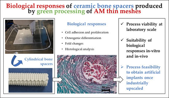
Abstract
1. Introduction
1.1. Implants in Use: The Case of the Bone Spacers
1.2. Additive Manufacturing for the Fabrication of Implants
1.3. Biological Responses of Nowadays’ Implants
2. Materials and Methods
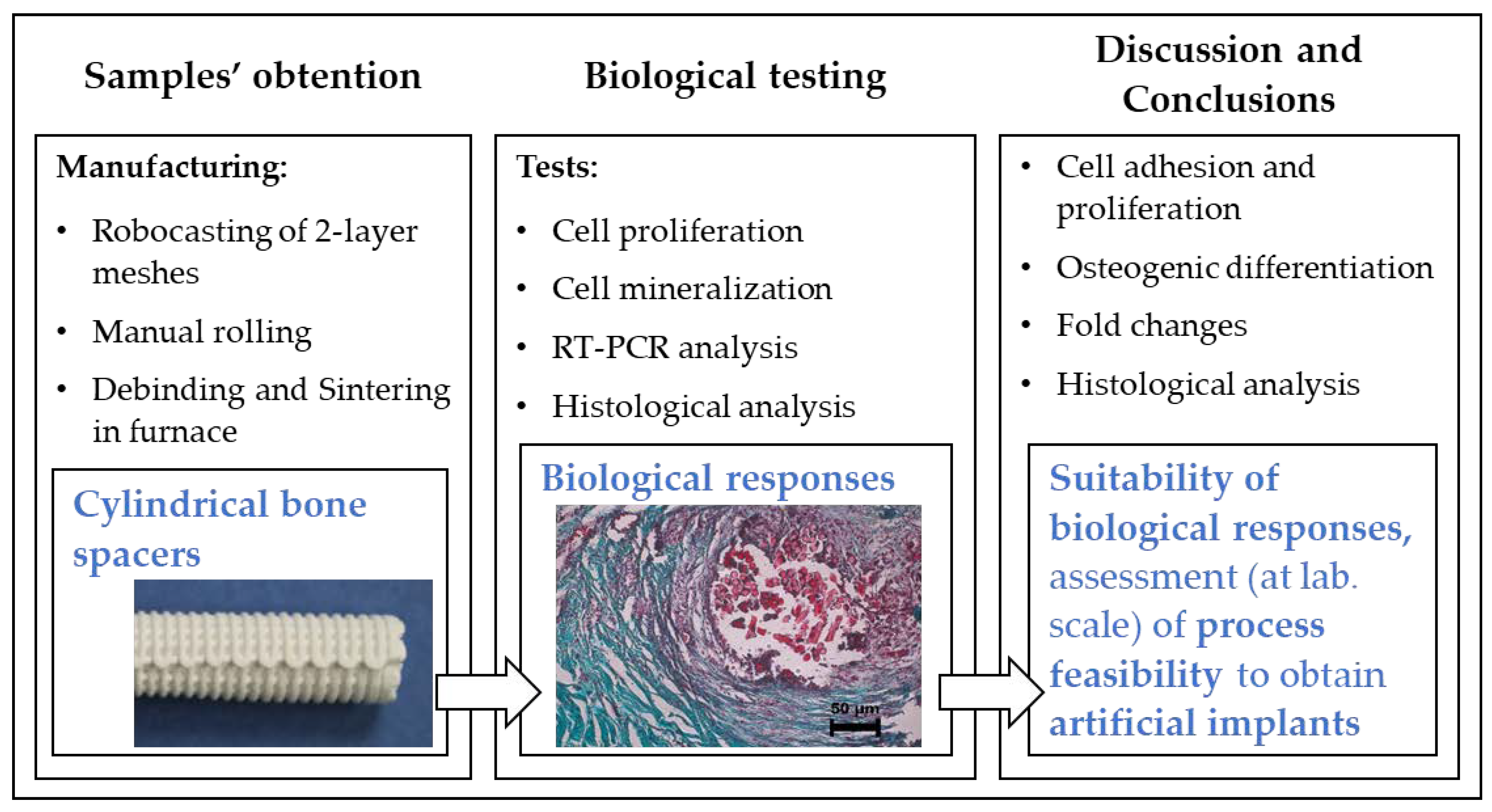
2.1. Overview of the Study
2.2. Implant Samples Definition and Materials
2.3. Manufacturing of Implant Samples
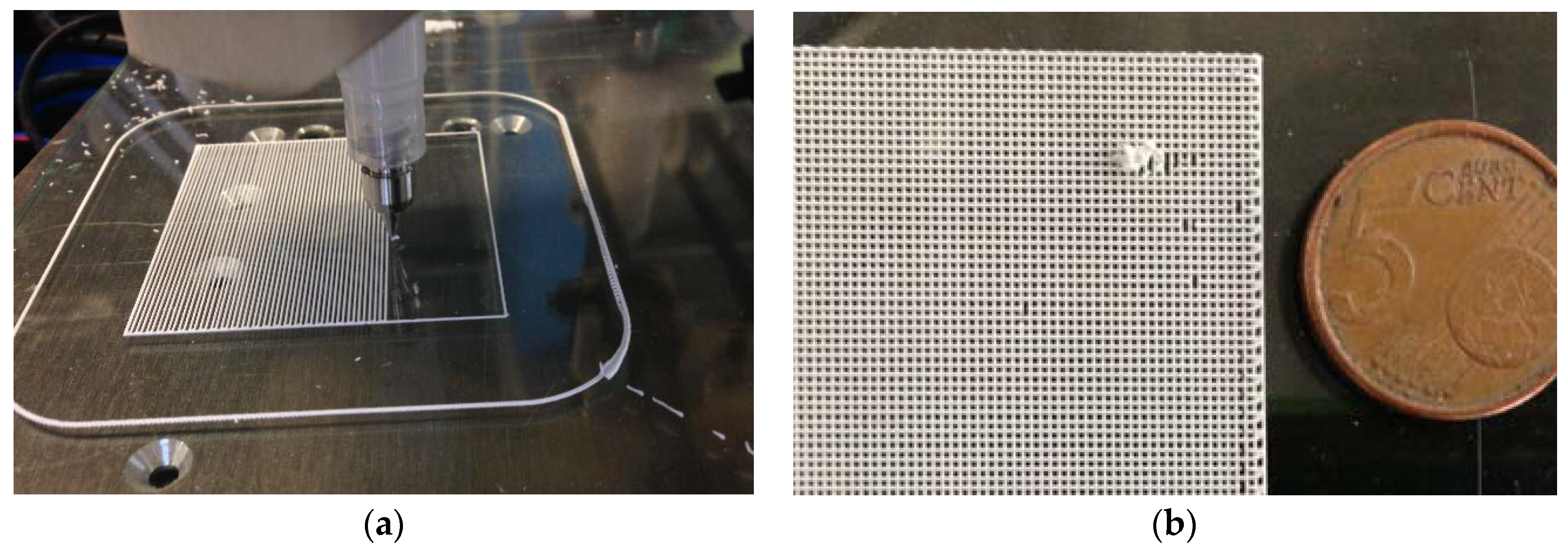
2.3.1. Robocasting of Ceramic Meshes
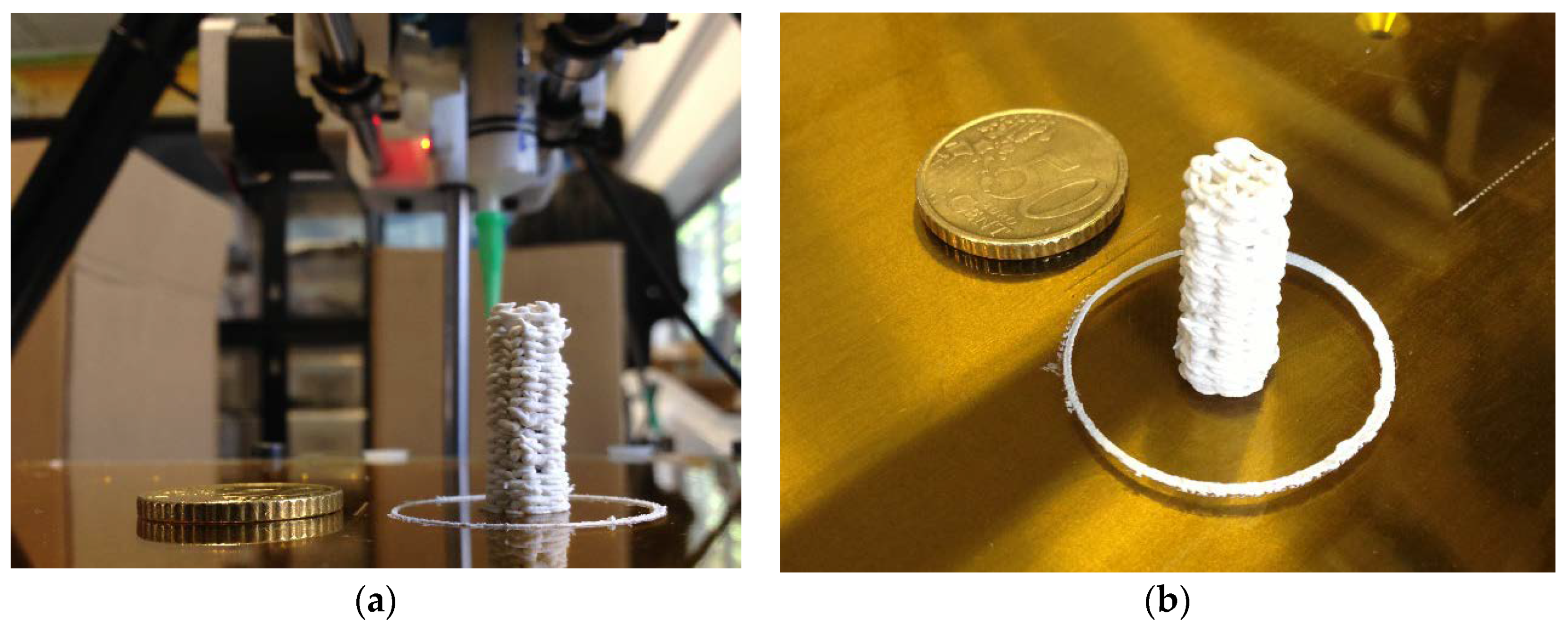
2.3.2. Processing of Green Ceramic Meshes into Bone Spacer Shapes
2.3.3. Heat Treatments
2.4. Biological Tests
2.4.1. Proliferation Test
2.4.2. Osteoblastic Marker Analysis
2.4.3. RT-PCR Analysis
2.4.4. Subcutaneous Implantation and Histological Analysis
3. Results
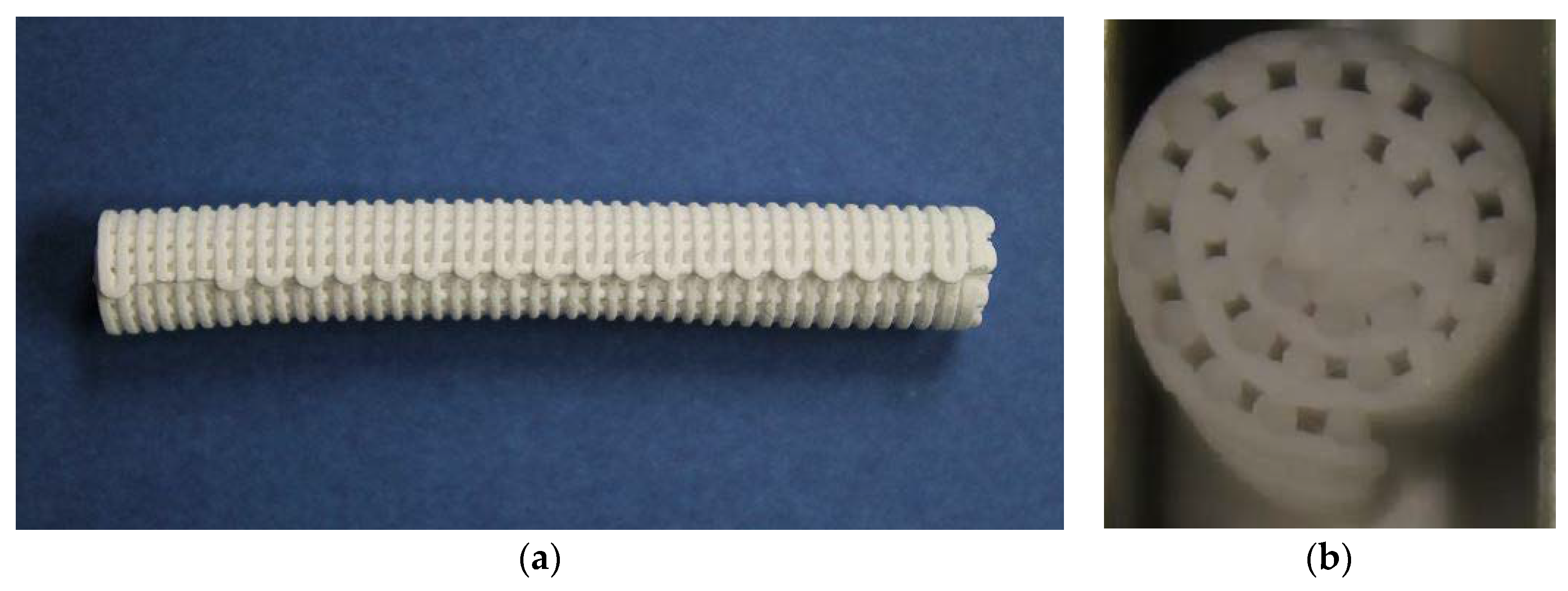
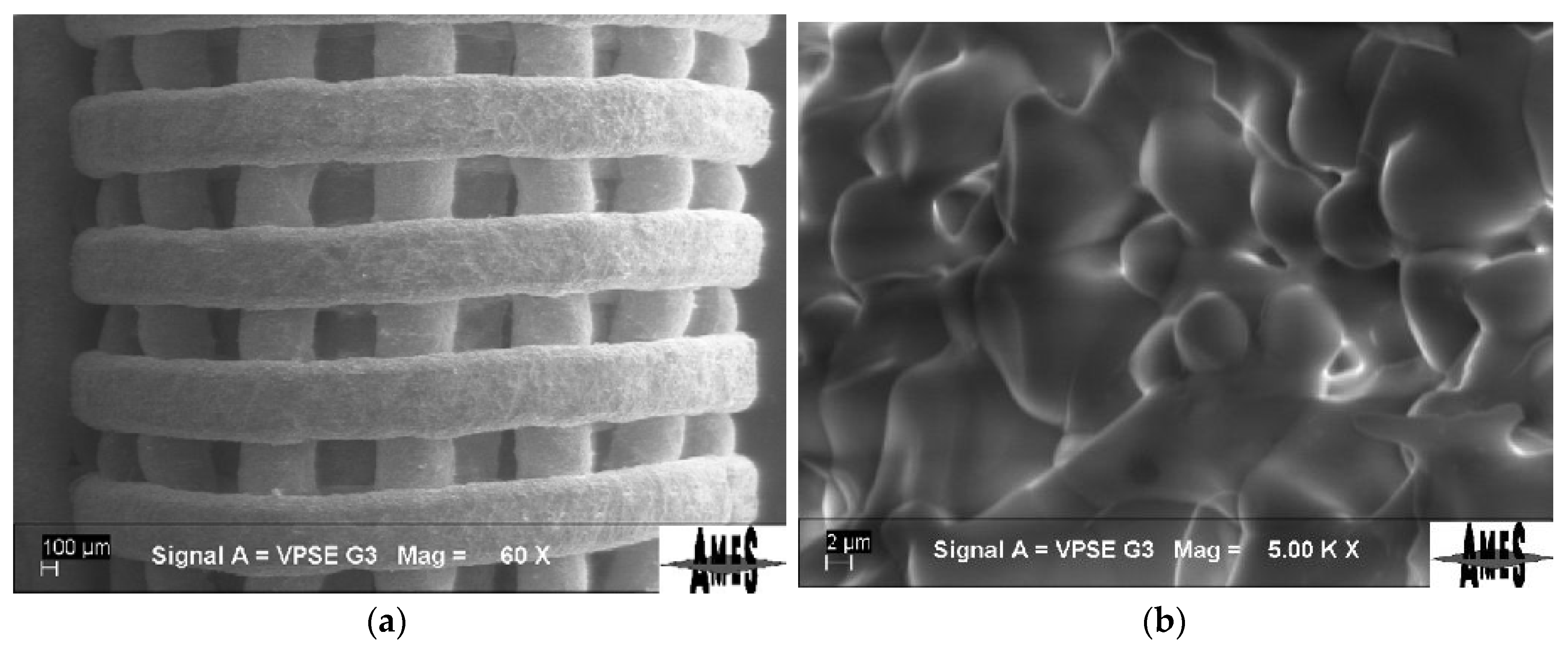
3.1. Production of the Samples Utilising the New Process
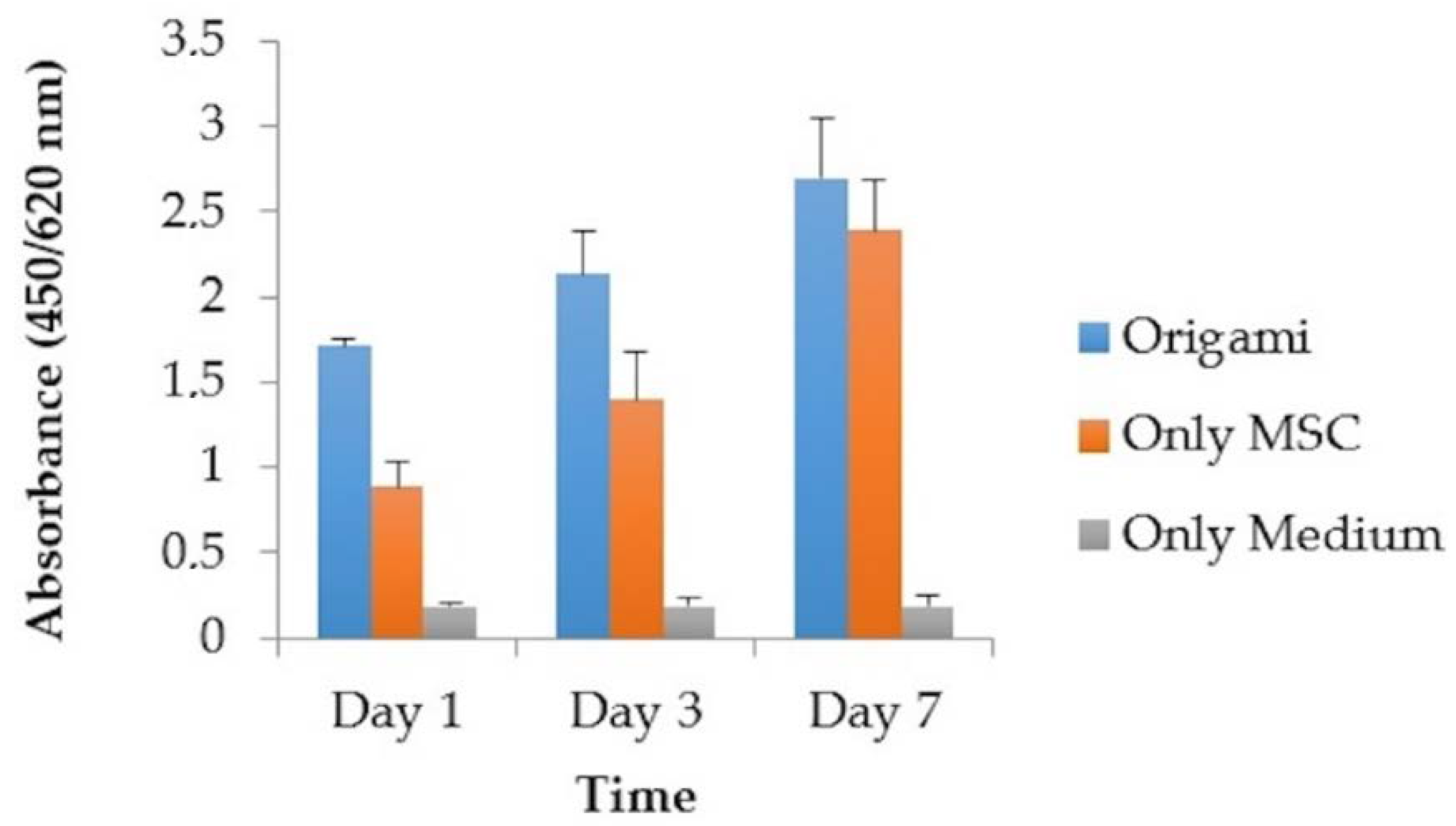
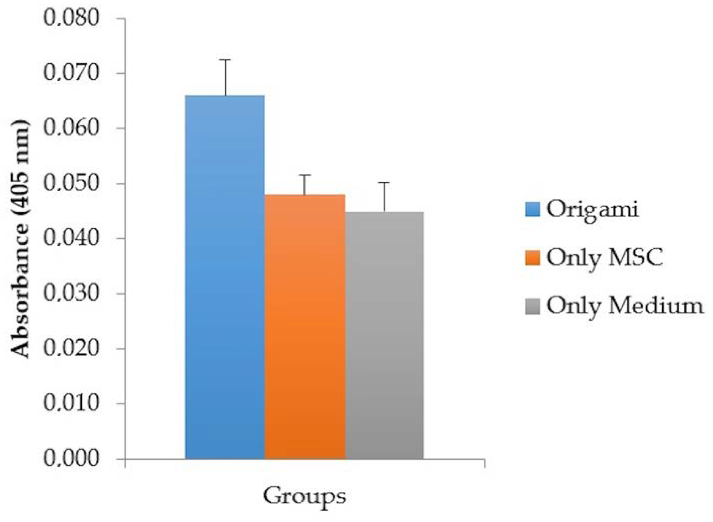
3.2. Cell Proliferation
3.3. Osteogenic Activity
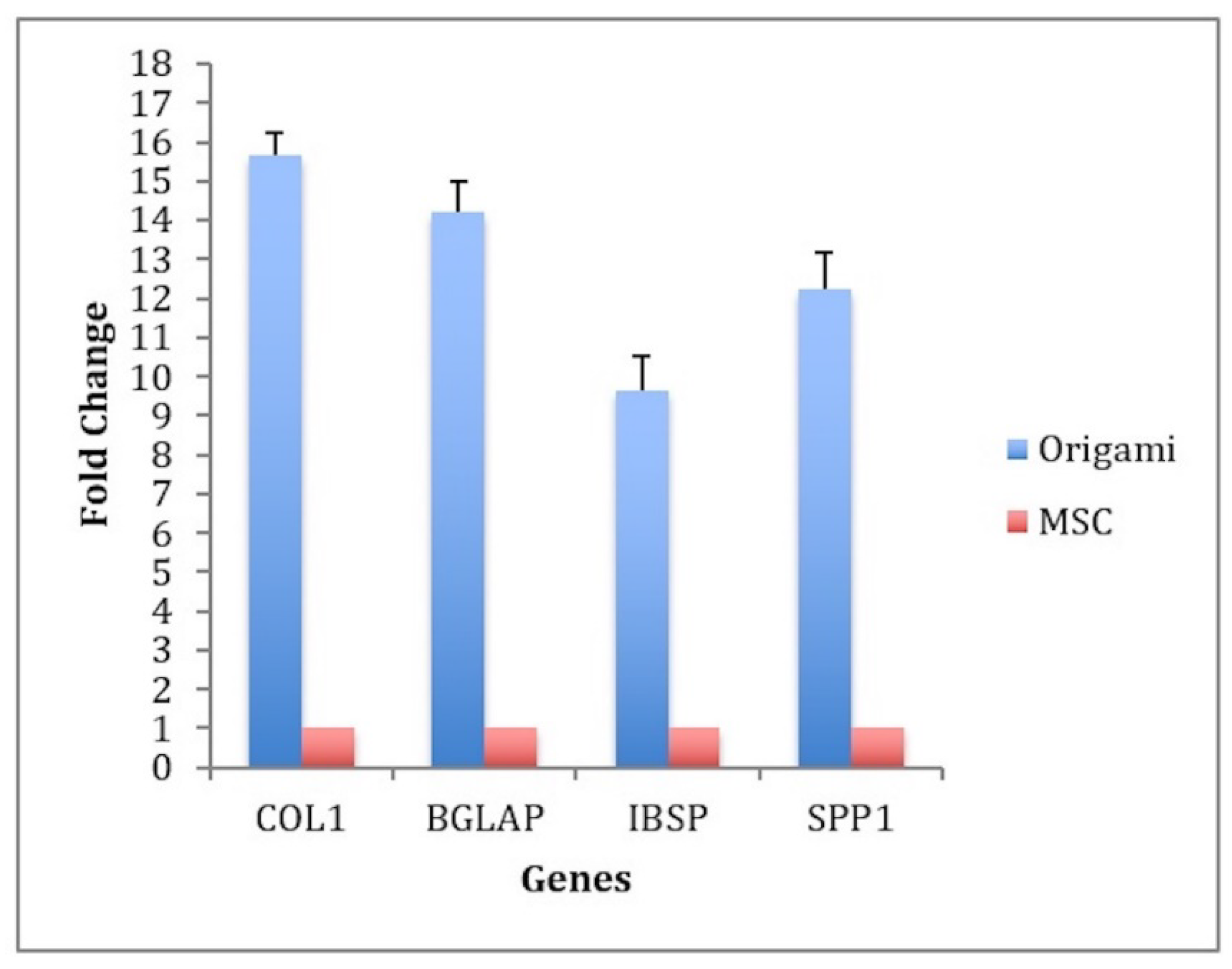
3.4. RT-PCR Analysis
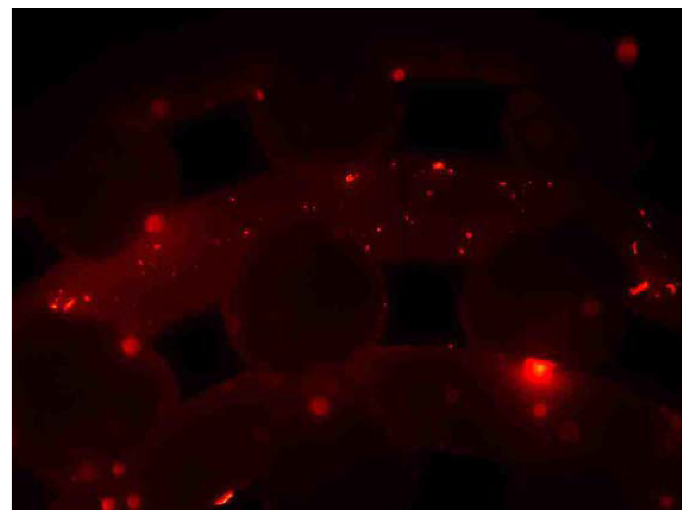
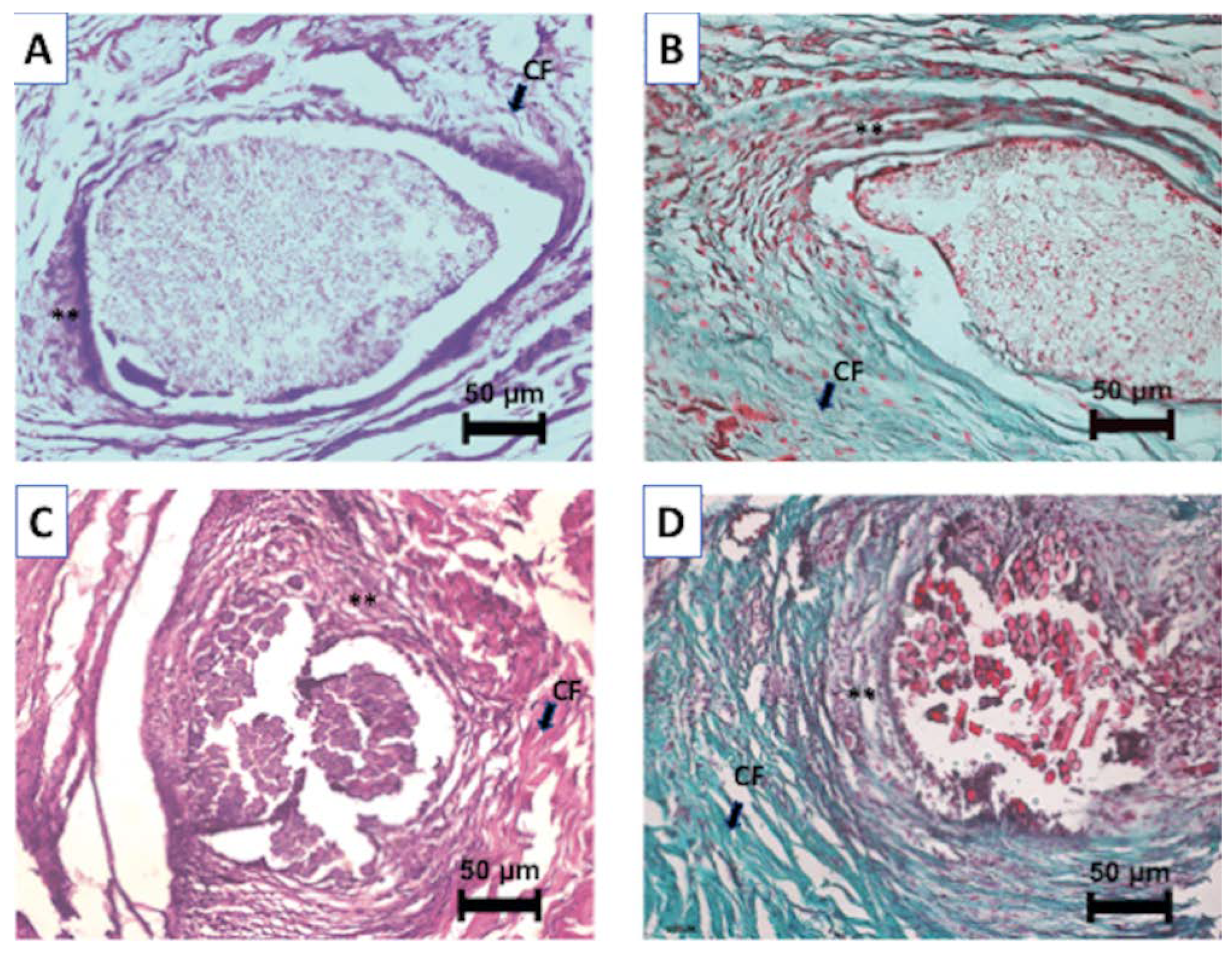
3.5. Histological Analysis
4. Discussion
5. Conclusions
Author Contributions
Funding
Acknowledgments
Conflicts of Interest
References
- Korkusuz, F.; Timuçin, M.; Korkusuz, P. Nanocrystalline Apatite-Based Biomaterials and Stem Cells in Orthopaedics. In Advances in Calcium Phosphate, Biomaterials-Springer Series in Biomaterials Science and Engineering; Ben-Nissan, B., Ed.; Springer: Berlin/Heidelberg, Germany, 2014; pp. 373–390. ISBN 978-3-642-53979-4. [Google Scholar]
- Kankılıç, B.; Çiftçi Dede, E.; Korkusuz, P.; Timuçin, M.; Korkusuz, F. Apatites for Orthopedic Applications. In Clinical Applications of Biomaterials; Kaur, G., Ed.; Springer: Berlin/Heidelberg, Germany, 2017; pp. 65–90. ISBN 978-3-319-56058-8. [Google Scholar]
- Korkusuz, P.; Korkusuz, F. Hard-tissue biomaterial interactions. In Biomaterials in Orthopedics; Yaszemski, M.J., Ed.; CRC Press: Boca Raton, FL, USA, 2003. [Google Scholar]
- Yang, Y.; Wang, G.; Liang, H.; Gao, C.; Peng, S.; Shen, L.; Shuai, C. Additive manufacturing of bone scaffolds. Int. J. Bioprint. 2019, 5, 148. [Google Scholar] [CrossRef]
- Shirazi, F.S.; Mehrali, M.; Oshkour, A.A.; Metselaar, H.S.C.; Kadri, N.A.; Osman, N.A. Mechanical and physical properties of calcium silicate/alumina composite for biomedical engineering applications. J. Mech. Behav. Biomed. Mater. 2014, 30, 168–175. [Google Scholar] [CrossRef] [PubMed]
- Hulbert, S.F. The use of alumina and zirconia in surgical implants. Adv. Ser. Ceram. 1993, 1, 25–40. [Google Scholar]
- Nakonieczny, D.S.; Antonowicz, M.; Paszenda, Z.K.; Radko, T.; Drewniak, S.; Bogacz, W.; Krawczyk, C. Experimental investigation of particle size distribution and morphology of alumina-yttria-ceria-zirconia powders obtained via sol–gel route. Biocybern. Biomed. Eng. 2018, 38, 535–543. [Google Scholar] [CrossRef]
- Nakonieczny, D.S.; Paszenda, Z.K.; Basiaga, M.; Radko, T.; Drewniak, S.; Podwórny, J.; Bogacz, W. Phase composition and morphology characteristics of ceria-stabilized zirconia powders obtained via sol-gel method with various pH conditions. Acta Bioeng. Biomech. 2017, 19, 21–30. [Google Scholar]
- Pighinelli, L.; Kucharska, M. Chitosan–hydroxyapatite composites. Carbohydr. Polym. 2013, 93, 256–262. [Google Scholar] [CrossRef]
- Reis, E.C.C.; Borges, A.P.B.; Fonseca, C.C.; Martinez, M.M.M.; Eleotério, R.B.; Morato, G.O.; Oliveira, P.M. Biocompatibility, osteointegration, osteoconduction, and biodegradation of a hydroxyapatite-polyhydroxybutyrate composite. Braz. Arch. Boil. Technol. 2010, 53, 817–826. [Google Scholar] [CrossRef]
- Dolcimascolo, A.; Calabrese, G.; Conoci, S.; Parenti, R. Innovative Biomaterials for Tissue Engineering. In Biomaterial-Supported Tissue Reconstruction or Regeneration; IntechOpen: London, UK, 2019. [Google Scholar] [CrossRef]
- Merola, M.; Affatato, S. Materials for hip prostheses: A review of wear and loading considerations. Materials 2019, 12, 495. [Google Scholar] [CrossRef]
- Pazourková, L.; Reli, M.; Hundáková, M.; Pazdziora, E.; Predoi, D.; Martynková, G.S.; Lafdi, K. Study of the structure and antimicrobial activity of Ca-deficient ceramics on chlorhexidine nanoclay substrate. Materials 2019, 12, 2996. [Google Scholar] [CrossRef]
- Ayats, J.R.G.; Canela, J.M. Development of a methodology for the materialisation of ceramic rapid prototypes based on substractive methods. Arch. Mater. Sci. 2007, 28, 9–14. [Google Scholar]
- Minguella-Canela, J.; Cuiñas, D.; Rodríguez, J.V.; Vivancos, J. Advanced manufacturing of ceramics for biomedical applications: Subjection methods for biocompatible materials. Procedia Eng. 2013, 63, 218–224. [Google Scholar] [CrossRef]
- Minguella-Canela, J.; Morales Planas, S.; Gomà Ayats, J.R.; De los Santos López, M.A. Assessment of the Potential Economic Impact of the Use of AM Technologies in the Cost Levels of Manufacturing and Stocking of Spare Part Products. Materials 2018, 11, 1429. [Google Scholar] [CrossRef] [PubMed]
- Dziaduszewska, M.; Wekwejt, M.; Bartmanski, M.; Pałubicka, A.; Gajowiec, G.; Seramak, T.; Osyczka, A.M.; Zielinski, A. The Effect of Surface Modification of Ti13Zr13Nb Alloy on Adhesion of Antibiotic and Nanosilver-Loaded Bone Cement Coatings Dedicated for Application as Spacers. Materials 2019, 12, 2964. [Google Scholar] [CrossRef] [PubMed]
- Oungeun, P.; Rojanathanes, R.; Pinsornsak, P.; Wanichwecharungruang, S. Sustaining Antibiotic Release from a Poly(methyl methacrylate) Bone-Spacer. ACS Omega 2019, 4, 14860–14867. [Google Scholar] [CrossRef]
- Beenken, K.E.; Smith, J.K.; Skinner, R.A.; Mclaren, S.G.; Bellamy, W.; Gruenwald, M.J.; Spencer, H.J.; Jennings, J.A.; O’Haggard, W.; Smeltzer, M.S. Chitosan coating to enhance the therapeutic efficacy of calcium sulfate-based antibiotic therapy in the treatment of chronic osteomyelitis. J. Biomat. Applicat. 2014. [Google Scholar] [CrossRef]
- Coraça-Huber, D.C.; De Rezende Duek, E.A.; Etchebehere, M.; Magna, L.A.; Amstalden, E.M.I. The use of vancomycin-loaded poly-l-lactic acid and poly-ethylene oxide microspheres for bone repair: An in vivo study. Clinics 2012, 67, 793–798. [Google Scholar] [CrossRef]
- Masquelet, A.C.; Fitoussi, F.; Begue, T.; Muller, G.P. Reconstruction of the long bones by the induced membrane and spongy autograft. Ann. Chir. Plast. Esthet. 2000, 45, 346–353. [Google Scholar]
- Koc, B.; Acar, A.A.; Weightman, A.; Cooper, G.; Blunn, G.; Bártolo, P. Biomanufacturing of customized modular scaffolds for critical bone defects. CIRP Ann. Manuf. Technol. 2019, 68, 209–212. [Google Scholar] [CrossRef]
- Ashman, O.; Phillips, A.M. Treatment of non-unions with bone defects: Which option and why? Injury Int. J. Care Inj. 2013, 44, S43–S45. [Google Scholar] [CrossRef]
- Unal, M.; Creecy, A.; Nyman, J.S. The role of matrix composition in the mechanical behavior of bone. Curr. Osteoporos. Rep. 2018, 16, 205–215. [Google Scholar] [CrossRef]
- Constant, C.; Nichols, S.; Wagnac, É.; Petit, Y.; Desrochers, A.; Braïlovski, V. Biocompatibility and Mechanical Stability of Nitinol as Biomaterial for Intra-Articular Prosthetic Devices. Materialia 2020, 100567. [Google Scholar] [CrossRef]
- Bayraktar, H.H.; Morgan, E.F.; Niebur, G.L.; Morris, G.E.; Wong, E.K.; Keaveny, T.M. Comparison of the elastic and yield properties of human femoral trabecular and cortical bone tissue. J. Biomech. 2004, 37, 27–35. [Google Scholar] [CrossRef]
- Naik, K.S. Advanced bioceramics. In Advances in Biological Science Research; Academic Press: Cambridge, MA, USA, 2019; pp. 411–417. [Google Scholar] [CrossRef]
- Bourell, D.; Kruth, J.P.; Leu, M.; Levy, G.; Rosen, D.; Beese, A.M.; Clare, A. Materials for additive manufacturing. CIRP Ann. 2017, 66, 659–681. [Google Scholar] [CrossRef]
- Buj-Corral, I.; Petit-Rojo, O.; Bagheri, A.; Minguella-Canela, J. Modelling of porosity of 3D printed ceramic prostheses with grid structure. Procedia Manuf. 2017, 13, 770–777. [Google Scholar] [CrossRef]
- Cesarano, J.; Segalman, R.; Calvert, P. Robocasting provides moldless fabrication from slurry deposition. Ceram Ind. 1998, 148, 94–102. [Google Scholar]
- Smay, J.E.; Cesarano, J.; Lewis, J.A. Colloidal Inks for Directed Assembly of 3-D Periodic Structures. Langmuir 2002, 18, 5429–5437. [Google Scholar] [CrossRef]
- Michna, S.; Wu, W.; Lewis, J.A. Concentrated hydroxyapatite inks for direct-write assembly of 3-D periodic scaffolds. Biomaterials 2005, 26, 5632–5639. [Google Scholar] [CrossRef]
- Miranda, P.; Saiz, E.; Gryn, K.; Tomsia, A.P. Sintering and robocasting of β-tricalcium phosphate scaffolds for orthopaedic applications. Acta Biomater. 2006, 2, 457–466. [Google Scholar] [CrossRef]
- Minguella-Canela, J.; Villegas, M.; Poll, B.; Tena, G.; Ginebra, M.P. Automatic casting of advanced technical ceramic parts via open source high resolution 3D printing machines. Key Eng. Mater. 2014, 631, 269–274. [Google Scholar] [CrossRef]
- Fu, Q.; Saiz, E.; Tomsia, A.P. Direct ink writing of highly porous and strong glass scaffolds for load-bearing bone defects repair and regeneration. Acta Biomater. 2011, 7, 3547–3554. [Google Scholar] [CrossRef]
- Chartier, T.; Dupas, C.; Lasgorceix, M.; Brie, J.; Champion, E.; Delhote, N.; Chaput, C. Additive Manufacturing fo Produce complex 3D ceramic parts. J. Ceram. Sci. Tech. 2015, 6, 95–104. [Google Scholar] [CrossRef]
- Altun, A.A.; Prochaska, T.; Konegger, T.; Schwentenwein, M. Dense, Strong, and Precise Silicon Nitride-Based Ceramic Parts by Lithography-Based Ceramic Manufacturing. Appl. Sci. 2020, 10, 996. [Google Scholar] [CrossRef]
- Schwentenwein, M.; Schneider, P.; Homa, J. Lithography-Based Ceramic Manufacturing: A Novel Technique for Additive Manufacturing of High-Performance Ceramics. Adv. Sci. Technol. 2014, 88, 60–64. [Google Scholar] [CrossRef]
- Schwarzer, E.; Götz, M.; Markova, D.; Stafford, D.; Scheithauer, U.; Moritz, T. Lithography-based ceramic manufacturing (LCM)–Viscosity and cleaning as two quality influencing steps in the process chain of printing green parts. J. Eur. Ceram. Soc. 2017, 37, 5329–5338. [Google Scholar] [CrossRef]
- Ahlhelm, M.; Günther, P.; Scheithauer, U.; Schwarzer, E.; Günther, A.; Slawik, T.; Moritz, T.; Michaelis, A. nnovative and novel manufacturing methods of ceramics and metal-ceramic composites for biomedical applications. J. Eur. Ceram. Soc. 2016, 36, 2883–2888. [Google Scholar] [CrossRef]
- Zhang, X.Y.; Fang, G.; Zhou, J. Additively manufactured scaffolds for bone tissue engineering and the prediction of their mechanical behavior: A review. Materials 2017, 10, 50. [Google Scholar] [CrossRef]
- Patel, P.P.; Buckley, C.; Taylor, B.L.; Sahyoun, C.C.; Patel, S.D.; Mont, A.J.; Mai, L.; Patel, S.; Freeman, J.W. Mechanical and biological evaluation of a hydroxyapatite-reinforced scaffold for bone regeneration. J. Biomed. Mater. Res. A 2019, 107, 732–741. [Google Scholar] [CrossRef]
- Li, B.; Liu, Z.; Yang, J.; Yi, Z.; Xiao, W.; Liu, X.; Liao, X. Preparation of bioactive β-tricalcium phosphate microspheres as bone graft substitute materials. Mater. Sci. Eng. C 2017, 70, 1200–1205. [Google Scholar] [CrossRef]
- Baino, F.; Minguella-Canela, J.; Korkusuz, F.; Korkusuz, P.; Kankılıç, B.; Montealegre, M.A.; De los Santos-López, M.A.; Vitale-Brovarone, C. In vitro assessment of bioactive glass coatings on alumina/zirconia composite implants for potential use in prosthetic application. Int. J. Mol. Sci. 2019, 20, 722. [Google Scholar] [CrossRef]
- Huang, B.; Caetano, G.; Vyas, C.; Blaker, J.; Diver, C.; Bártolo, P. Polymer-ceramic composite scaffolds: The effect of hydroxyapatite and β-tri-calcium phosphate. Materials 2018, 11, 129. [Google Scholar] [CrossRef]
- Adel-Khattab, D.; Giacomini, F.; Gildenhaar, R.; Berger, G.; Gomes, C.; Linow, U.; Hardt, M.; Peleska, B.; Günster, J.; Stiller, M.; et al. Development of a synthetic tissue engineered three-dimensional printed bioceramic-based bone graft with homogenously distributed osteoblasts and mineralizing bone matrix in vitro. J. Tissue Eng. Regen. Med. 2018, 12, 44–58. [Google Scholar] [CrossRef] [PubMed]
- Korkusuz, F.; Uluoğlu, Ö. Non-specific inflammation and bone marrow depletion due to intramedullary porous hydroxyapatite application. Bull Hosp. Joint Dis. 1999, 58, 86–91. [Google Scholar]
- Korkusuz, F.; Korkusuz, P.; Ekşioğlu, F.; Gürsel, İ.; Hasırcı, V. In vivo response to biodegradable controlled antibiotic release systems. J. Biomed. Mater. Res. 2001, 55, 217–228. [Google Scholar] [CrossRef]
- Koç, N.; Timuçin, M.; Korkusuz, F. Fabrication and characterization of porous tricalcium phosphate ceramics. Ceram. Int. 2004, 30, 205–211. [Google Scholar] [CrossRef]
- Koç, N.; Timuçin, M.; Korkusuz, F. Fabrication and characterization of porous hydroxyapatite and biphasic calcium phosphate ceramic as bone substitutes. Key Eng. Mat. 2004, 254–256, 949–952. [Google Scholar] [CrossRef]
- Emül, E.; Sağlam, S.; Ateş, H.; Korkusuz, F.; Sağlam, N. Characterization of electrospun nanofibrous scaffolds for nanobiomedicine. J. Electron. Mater. 2016, 45, 3835–3845. [Google Scholar] [CrossRef]
- Ohtsuru, T.; Morita, Y.; Murata, Y.; Munakata, Y.; Itoh, M.; Kato, Y.; Okazaki, K. Custom-made, antibiotic-loaded, acrylic cement spacers using a dental silicone template for treatment of infected hip prostheses. Eur. J. Orthop. Surg. Traumatol. 2018, 28, 615. [Google Scholar] [CrossRef]
- Pérez, R.A.; Mestres, G. Role of pore size and morphology in musculo-skeletal tissue regeneration. Mat. Sci. Eng. C 2016, 61, 922–939. [Google Scholar] [CrossRef]
- Baino, F.; Montealegre, M.A.; Minguella-Canela, J.; Vitale-Brovarone, C. Laser Surface Texturing of Alumina/Zirconia Composite Ceramics for Potential Use in Hip Joint Prosthesis. Coatings 2019, 9, 369. [Google Scholar] [CrossRef]
- Brazete, D.; Torres, P.M.C.; Abrantes, J.C.C.; Ferreira, J.M.F. Influence of the Ca/P ratio and cooling rate on the allotropic αβ-tricalcium phosphate phase transformations. Ceram. Int. 2018, 44, 8249–8256. [Google Scholar] [CrossRef]
- Gomà-Ayats, J.R.; Minguella-Canela, J.; Uceda-Molera, R. Challenges and opportunities in obtaining rapid ceramic components by means of subtractive methods applied to non-sintered materials. In Innovative Developments in Design and Manufacturing, Proceedings of the VRAP-Advanced Research in Virtual and Rapid Prototyping, Leiria, Portugal, 29 October 2009; CRC Press: London, UK, 2009. [Google Scholar] [CrossRef]
- Kang, Y.; Kim, S.; Fahrenholtz, M.; Khademhosseini, A.; Yang, Y. Osteogenic and angiogenic potentials of monocultured and co-cultured human-bone-marrow-derived mesenchymal stem cells and human-umbilical-vein endothelial cells on three-dimensional porous beta-tricalcium phosphate scaffold. Acta Biomater. 2013, 9, 4906–4915. [Google Scholar] [CrossRef] [PubMed]
- Gizer, M.; Köse, S.; Karaosmanoglu, B.; Taskiran, E.Z.; Berkkan, A.; Timuçin, M.; Korkusuz, F.; Korkusuz, P. The Effect of boron-containing nano-hydroxyapatite on bone cells. Biol. Trace Elem. Res. 2020, 193, 364–376. [Google Scholar] [CrossRef] [PubMed]
- Yang, X.; Li, Y.; He, W.; Huang, Q.; Zhang, R.; Feng, Q. Hydroxyapatite/collagen coating on PLGA electrospun fibers for osteogenic differentiation of bone marrow mesenchymal stem cells. J. Biomed. Mater. Res. Part A 2018, 106, 2863–2870. [Google Scholar] [CrossRef] [PubMed]
- Halloran, J.W. Ceramic stereolithography: Additive manufacturing for ceramics by photopolymerization. Annu. Rev. Mater. Res. 2016, 46, 19–40. [Google Scholar] [CrossRef]
- Fina, F.; Goyanes, A.; Madla, C.M.; Awad, A.; Trenfield, S.J.; Kuek, J.M.; Patel, P.; Gaisford, S.; Basit, A.W. 3D printing of drug-loaded gyroid lattices using selective laser sintering. Int. J. Pharm. 2018, 547, 44–52. [Google Scholar] [CrossRef] [PubMed]
- Moreno Madrid, A.P.; Vrech, S.M.; Sanchez, M.A.; Rodriguez, A.P. Advances in additive manufacturing for bone tissue engineering scaffolds. Mater. Sci. Eng. C 2019, 100, 631–644. [Google Scholar] [CrossRef]
- Mohan, N.; Senthil, P.; Vinodh, S.; Jayanth, N. A review on composite materials and process parameters optimisation for the fused deposition modelling process. Virtual Phys. Prototyp. 2017, 12, 47–59. [Google Scholar] [CrossRef]
- Griffith, M.L.; Chu, T.-M.; Wagner, W.; Halloran, J.W. Ceramic stereolithography for investment casting and biomedical applications. In International Solid Freeform Fabrication Symposium; The University of Michigan: Ann Arbor, MI, USA, 1995. [Google Scholar]
- Zhang, Y.; Hao, L.; Savalani, M.M.; Harris, R.A.; Tanner, K.E. Characterization and dynamic mechanical analysis of selective laser sintered hydroxyapatite-filled polymeric composites. J. Biomed. Mater. Res. A 2008, 86, 607–616. [Google Scholar] [CrossRef]
- Tan, K.H.; Chua, C.K.; Leong, K.F.; Cheah, C.M.; Cheang, P.; Abu Bakar, M.S.; Cha, S.W. Scaffold development using selective laser sintering of polyetheretherketone hydroxyapatite biocomposite blends. Biomaterials 2003, 24, 3115–3123. [Google Scholar] [CrossRef]
- Charrière, E.; Lemaitre, J.; Zysset, P. Hydroxyapatite cement scaffolds with controlled macroporosity: Fabrication protocol and mechanical properties. Biomaterials 2003, 24, 809–817. [Google Scholar] [CrossRef]
- Koh, Y.-H.; Jun, I.-K.; Kim, H.-E. Fabrication of poly(εcaprolactone)/hydroxyapatite scaffold using rapid direct deposition. Mater. Lett. 2006, 60, 1184–1187. [Google Scholar] [CrossRef]
- Baino, F.; Minguella, J.; Kirk, N.; Montealegre, M.A.; Fiaschi, C.; Korkusuz, F.; Orlygsson, G.; Vitale-Brovarone, C. Novel full-ceramic monoblock acetabular cup with a bioactive trabecular coating: Design, fabrication and characterization. Ceram. Int. 2016, 42, 6833–6845. [Google Scholar] [CrossRef]
- Baino, F.; Tallia, F.; Novajra, G.; Minguella, J.; Montealegre, M.A.; Korkusuz, F.; Vitale-Brovarone, C. Novel Bone-Like Porous Glass Coatings on Al2O3 Prosthetic Substrates. Key Eng. Mater. 2014, 631, 236–240. [Google Scholar] [CrossRef]
- Klawitter, J.J.; Hulbert, S.F. Application of porous ceramics for the attachment of load bearing internal orthopedic applications. J. Biomed. Mater. Res. 1971, 5, 161–229. [Google Scholar] [CrossRef]
- Itala, A.I.; Ylanen, H.O.; Ekholm, C.; Karlsson, K.H.; Aro, H.T. Pore diameter of more than 100 μm is not requisite for bone ingrowth in rabbits. J. Biomed. Mater. Res. 2001, 58, 679–683. [Google Scholar] [CrossRef]
- Tamai, N.; Myoui, A.; Tomita, T.; Nakase, T.; Tanaka, J.; Ochi, T.; Yoshikawa, H. Novel hydroxyapatite ceramics with an interconnective porous structure exhibit superior osteoconduction in vivo. J. Biomed. Mater. Res. 2002, 59, 110–117. [Google Scholar] [CrossRef]
- Saiz, E.; Gremillard, L.; Menendez, G.; Miranda, P.; Gryn, K.; Tomsia, A.P. Preparation of porous hydroxyapatite scaffolds. Mater. Sci. Eng. C 2007, 27, 546–550. [Google Scholar] [CrossRef]
- Cha, M.; Lee, K.M.; Lee, J.H. Positive effects of bisphosphonates on osteogenic differentiation in patient-derived mesenchymal stem cells for the treatment of osteoporosis. Tissue Eng. Regen. Med. 2018, 15, 467–475. [Google Scholar] [CrossRef]
- Zadpoor, A.A.; Malda, J. Additive Manufacturing of Biomaterials, Tissues, and Organs. Ann. Biomed. Eng. 2017, 45, 1–11. [Google Scholar] [CrossRef]
- Milazzo, M.; Contessi Negrini, N.; Scialla, S.; Marelli, B.; Farè, S.; Danti, S.; Buehler, M.J. Additive Manufacturing Approaches for Hydroxyapatite-Reinforced Composites. Adv. Funct. Mater. 2019, 1903055. [Google Scholar] [CrossRef]


| Parameter | Value |
|---|---|
| No. Of struts in the ‘x’ direction | 45 |
| Length of the struts in the ‘x’ direction | 58.65 mm |
| Total length to be printed in the ‘x’ direction | 2639.25 mm |
| No. Of struts in the ‘y’ direction | 35 |
| Length of the struts in the ‘y’ direction | 75.65 mm |
| Total length to be printed in the ‘y’ direction | 2647.75 mm |
| Total length to be printed | 5287 mm |
| Printing speed | 10 mm/s |
| Total time to print the struts in ‘x’ and ‘y’ | 528.7 s |
| Time for changing from one layer to another | 5 s |
| Total time to print a sample | 533.7 s |
| Parameter | Value |
|---|---|
| Total spacer height | 75.65 mm |
| Layer definition (layer height) | 0.85 mm |
| Number of layers required | 89 |
| Printing time per layer | 8 s |
| Time for changing from one layer to another | 5 s |
| Total time to print a sample | 1152 s |
| Parameter | Value |
|---|---|
| Length of the struts in the ‘x’ direction | 58.65 mm |
| Printing speed in the ‘x’ direction | 20 mm/s |
| Total time to print the ‘x’ direction struts | 2.93 s |
| Length of the struts in the ‘y’ direction | 75.65 mm |
| Printing speed in the ‘y’ direction | 20 mm/s |
| Total time to print the ‘y’ direction struts | 3.78 s |
| Total time to print all struts if not synchronous | 6.72 s |
| Parameter | Value for mesh (a) | Value for full structure (b) |
|---|---|---|
| Total height | 1.7 mm | 75.65 mm |
| Layer definition (layer height) | 0.1 mm | 0.1 mm |
| Number of layers needed | 17 | 757 |
| Total time to consolidate a layer | 1.5 s | 1.5 s |
| Total time to print the geometry | 25.5 s | 1135.5 s |
© 2020 by the authors. Licensee MDPI, Basel, Switzerland. This article is an open access article distributed under the terms and conditions of the Creative Commons Attribution (CC BY) license (http://creativecommons.org/licenses/by/4.0/).
Share and Cite
Minguella-Canela, J.; Calero, J.A.; Korkusuz, F.; Korkusuz, P.; Kankılıç, B.; Bilgiç, E.; De los Santos-López, M.A. Biological Responses of Ceramic Bone Spacers Produced by Green Processing of Additively Manufactured Thin Meshes. Materials 2020, 13, 2497. https://doi.org/10.3390/ma13112497
Minguella-Canela J, Calero JA, Korkusuz F, Korkusuz P, Kankılıç B, Bilgiç E, De los Santos-López MA. Biological Responses of Ceramic Bone Spacers Produced by Green Processing of Additively Manufactured Thin Meshes. Materials. 2020; 13(11):2497. https://doi.org/10.3390/ma13112497
Chicago/Turabian StyleMinguella-Canela, Joaquim, Jose Antonio Calero, Feza Korkusuz, Petek Korkusuz, Berna Kankılıç, Elif Bilgiç, and M. Antonia De los Santos-López. 2020. "Biological Responses of Ceramic Bone Spacers Produced by Green Processing of Additively Manufactured Thin Meshes" Materials 13, no. 11: 2497. https://doi.org/10.3390/ma13112497
APA StyleMinguella-Canela, J., Calero, J. A., Korkusuz, F., Korkusuz, P., Kankılıç, B., Bilgiç, E., & De los Santos-López, M. A. (2020). Biological Responses of Ceramic Bone Spacers Produced by Green Processing of Additively Manufactured Thin Meshes. Materials, 13(11), 2497. https://doi.org/10.3390/ma13112497