Review

Photoelectrochemical Water Splitting Reaction System Based on Metal-Organic Halide Perovskites

1
Department of Materials Science and Engineering, Chonnam National University, Gwangju 61186, Korea
2
Department of Bioengineering, School of Engineering, The University of Tokyo, 7-3-1 Hongo, Bunkyo-ku, Tokyo 113-8656, Japan
3
Division of Mechanical Systems Engineering, Institute of Advanced Materials and Systems, Sookmyung Women’s University, Seoul 04310, Korea
*
Authors to whom correspondence should be addressed.
These authors contributed equally to this work.
Materials 2020, 13(1), 210; https://doi.org/10.3390/ma13010210
Submission received: 27 November 2019 / Revised: 31 December 2019 / Accepted: 2 January 2020 / Published: 3 January 2020
(This article belongs to the Special Issue Novel Materials for Sustainable Energy Conversion and Storage)

Abstract

:
In the development of hydrogen-based technology, a key challenge is the sustainable production of hydrogen in terms of energy consumption and environmental aspects. However, existing methods mainly rely on fossil fuels due to their cost efficiency, and as such, it is difficult to be completely independent of carbon-based technology. Electrochemical hydrogen production is essential, since it has shown the successful generation of hydrogen gas of high purity. Similarly, the photoelectrochemical (PEC) method is also appealing, as this method exhibits highly active and stable water splitting with the help of solar energy. In this article, we review recent developments in PEC water splitting, particularly those using metal-organic halide perovskite materials. We discuss the exceptional optical and electrical characteristics which often dictate PEC performance. We further extend our discussion to the material limit of perovskite under a hydrogen production environment, i.e., that PEC reactions often degrade the contact between the electrode and the electrolyte. Finally, we introduce recent improvements in the stability of a perovskite-based PEC device.

Graphical Abstract

1. Introduction

With continuously increasing energy consumption and pollution levels, enormous efforts have been made through international collaborations in various aspects to tackle energy challenges since the Kyoto Protocol and the Paris Climate Change Accord [1]. One major approach is to minimize the use of carbon-based energy sources, such as gas, coal, and natural gas, since such materials produce greenhouse gas as byproducts. Hydrogen has long been considered the most promising energy source as an alternative to existing carbon-based energy sources due to its high energy density and the cleanness of its energy conversion process. However, existing methods of hydrogen production, including thermochemical production, are often associated with the consumption of huge amounts of fossil fuel or with other forms of environmental damage. Therefore, the eco-friendly production of hydrogen is considered the main challenge in the development of hydrogen-based technology.
Electrochemical water splitting is a potential candidate for the sustainable and environmentally-friendly production of hydrogen fuel [2,3,4,5]. In addition to electrochemical methods, photoelectrochemical (PEC) water splitting has also been drawing attention as an environmentally-friendly hydrogen production method, as it enables very active and stable water splitting using light-sensitive semiconductors and molecular catalysts. Though metal oxides have been extensively researched as PEC water splitting photoanodes due to their long-term stability, a metal oxide having a large bandgap possesses a low photocurrent, as it is unable to sufficiently absorb the wavelengths of the visible light region [6,7,8]. Research has been conducted on the photoelectrochemical water splitting potential of perovskite, as a substitute for metal oxide, due to its potential for bandgap engineering and absorbing various wavelengths. Additionally, perovskite has a high absorption coefficient, long electron and hole diffusion length, and excellent electrical as well as optical properties. Hence, perovskite is gaining attention both as a next-generation solar cell material as well as a PEC cell material [9,10,11,12]. Also, perovskite-based PEC cell has advantages in most processes such as spin coating, and it can be deposited in a short time at low temperatures [13]. Despite outstanding properties, perovskite has a major drawback due to degradation caused by water. When Perovskite comes in contact with water, hydrolysis reactions occur, causing perovskite degradation and decreased performance [14,15]. While PEC requires the electrode and the electrolyte to be in contact with each other, degradation occurs when the perovskite and aqueous solution come into contact. Thus, several researchers have been investigating various passivation technologies for the long-term stability of perovskite-based PEC devices [16,17,18]. In this mini-review, we discuss recent progress on perovskite materials as promising candidates for PEC water splitting reactions and stability issues under aqueous operation, as well as the intrinsic properties about perovskite materials.

2. Properties of Materials and Mechanisms of the PEC Cell

2.1. Intrinsic Properties of Perovskite Materials

The general molecular formula of perovskite is ABO3; perovskite materials have a cubic lattice-nested octahedral layered structure. These materials have superior magnetic, ferroelectric, electrical, and optical properties, attracting attention for potential use in optoelectronic devices. At present, many research groups are actively investigating these characteristic properties, and recently, nuclear magnetic resonance (NMR) spectroscopy has been significantly used for analyzing the structure of these perovskite materials [19]. Perovskite materials also have low recombination probability and high carrier lifetimes and diffusion lengths [20,21]. Therefore, metal-organic halide perovskites have been amongst the most interesting subjects in optoelectronic materials research, and are utilized in various fields such as light-emitting diodes, solar cells, lasers, and photodetectors [22,23,24,25].
The metal-organic halide perovskite has a molecular structure of type ABX3, where A and B are cations (A is larger than B), and X is the anion. The general crystal structure of perovskite is shown in Figure 1a–c [26,27]. Perovskites commonly have unit cells consisting of five atoms in a cubic structure (α phase), where the A cation (methylammonium, CH3NH3+, MA+, or formamidinium, CH(NH2)2+, FA+) is surrounded by twelve X anions (Cl, Br, or I, or a coexistence of several halogens) to form a cuboctahedron, and the B cation (Pb2+, Sn2+, etc.) is located at the octahedral site of X. The B cation–X anion octahedra are joined together to form stable three-dimensional network structures [21,28]. To achieve a cubic structure with a high degree of high symmetry, i.e., an ideal perovskite crystal structure, the radius ratio of A, B, and X should be such that tolerance factor {t = (RA + RB)/ 2 ( RB + RX)} is close to 1 [29]. For the tolerance factor to approach 1, the A cation must be much larger than the B cation. In metal-organic halide perovskite, the A site must be occupied by a very large atom because the B site is usually occupied with a large atom such as Pb or Sn. Tolerance factors of cubic structures are generally between 0.89 and 1, where a tolerance factor lower than 0.89 could induce a tetragonal (β phase) or orthorhombic (γ phase) structure, whereas higher tolerance factors could induce a two-dimensional (2D) layer structure due to the unstable three-dimensional (3D) B–X bonding [7,30,31]. Actually, the transverse phonon easily displaces the X anion from the B–B intermediate location of the cubic structure [32,33]. The non-perovskite δ phase appears in perovskite materials such as HC(NH2)2PbI3, FAPbI3, CsPbI3, and CsSnI3, which, unlike the β and γ phases, is caused not by B–X–B angle distortion in the α phase, but by the breaking of the B–X bond [34,35,36].
As one of the unique properties of metal-organic halide perovskites, the optical properties of photo-generated charge carriers have been researched. The specific excitonic absorption peaks of the metal-organic halide perovskite could be transited to various absorption spectra, and it changed significantly in visible light through the adjustment of metal atoms and halogens (Figure 1d,e). Converting the metal atom directly changes the M–X bonding, resulting in changes in valence band maximum and conduction band minimum, as the band edge is determined by the metal orbitals of the B site. In fact, in perovskite, the valence band is composed of 5p orbitals of I and the s-antibonding states of Pb 6s. The conduction band is composed of 5s orbital of I and the s-antibonding states of Pb 6p. For example, when the B site is changed from Pb to Sn in MAPbI3, the bandgap changes from 1.57 to 1.17 eV, and therefore, the bandgap between 1.57 eV and 1.17 eV can be controlled by adjusting the ratio of Pb and Sn [37,38]. Additionally, converting the A organic cations changes the length and angle of the M–X–M bonding, which, in turn, changes the bandgap but does not affect the valence band maximum. In fact, MAPbI3 shows a rapid absorption rise at 825 nm (1.5 eV) and has a large absorption coefficient of 1.8 × 104 cm−1. By substituting the methylammonium (MA) cation with formamidinium (FA), the energy bandgap could be lowered to 1.48 eV, which reduces the bandgap by 0.09 eV and allows for additional light absorption [39]. Metal-organic halide perovskites are widely used in the optoelectronics field due to their excellent and wide-ranging absorbance in the visible light range [40]. Furthermore, metal-organic halide perovskites could exhibit amplified spontaneous emission due to the low defect density and slow Auger recombination, even in the presence of electron and hole extinctions [41,42]. The absorption coefficient of perovskite is affected by temperature, tending to decrease at lower temperatures. This is associated with the interaction of excitons and phonons at low temperatures and the phase transition of MAPbI3 at about 160 K (Figure 1f) [43]. Similar to light absorption, the photoluminescence (PL) of metal-organic halide perovskite could be tuned by changing organic cations or anions. In the case of MAPbI3 quantum dot (QD), the PL spectrum could be tuned from 407 to 734 nm by changing the composition of anions (Figure 1g) [44]. Due to its properties to tune the strong PL spectrum, perovskite is utilized in a variety of light-emitting applications including lasers, light-emitting diodes, and optical sensors [39,45,46,47].
A time-dependent photoluminescence (TDPL) measurement was performed to determine the carrier lifetime (τ) of single crystal FAPbI3. As a result, a peak was observed at 820 nm. The two-exponential decay showed fast (τ1 = 32 ns) and slow (τ2 = 484 ns) carrier lifetimes [15]. A short lifetime represents a high trap density on the crystal surface, while a long lifetime represents carrier transporting in bulk with fewer defects. Generally, FAPbI3 has a lower carrier lifetime than single-crystal MAPbI3 [48,49,50]. In the case of carrier mobility, it shows change with the perovskite phase transition. The mobility was measured at 35 cm at room temperature; the mobility tends to decrease with increasing temperature at all three steps. Most experimental values follow the T−3/2 dependency without discontinuity in phase transitions, and show 150 cm2 V−1 s−1 at 80 K. Mobility is relatively high when the temperature is above room temperature or when entering the cubic phase [10,51,52,53,54]. In addition, the change of carrier mobility is shown by the perovskite layer thickness. Zhang et al. [55] characterized the photovoltaic power conversion efficiency (PCE) with different MAPbI3 layer thicknesses to investigate the effect of film thickness on perovskite solar cell devices. The PCE increases as the film thickness approaches 300 nm and tends to decrease rapidly in the 300–530 nm range. The PCE has a maximum of about 10.16% at 300 nm thickness and decreases to 5.29% at 530 nm. This allowed us to determine the optimal thickness of the MAPbI3 layer. When thin, pinholes result in low VOC and shunt resistance, while increasing the thickness of the film eliminates this contact, thereby improving VOC. JSC is affected by light-harvesting efficiency(ηlh) and carrier injection efficiency(ηinj). The increase in JSC with increasing thickness up to 300 nm indicates that the increase in the absorber layer thickness results in higher absorption and higher ηlh [56,57,58].

2.2. Principle of Photoelectrochemical Water Splitting Reaction

The electrochemical reaction is based on the junction of the electrode and the electrolyte. In electrochemical water splitting, a hydrogen evolution reaction (HER) occurs at the cathode, and an oxygen evolution reaction (OER) occurs at the anode. The oxidation and reduction reactions for water splitting are as follows.
2H2O + 2e→H2(g) + 2OH, Eo = 0.00 V (HER)
2OH→1/2 O2(g) + H2O + 2e, E = 1.23 V (OER)
The theoretical potential required for electrochemical water splitting is 1.23 V. However, due to the activation energy required for the reaction, more than 1.23 V is required in practice. In other words, the actual response requires a theoretical value of 1.23 V or higher. The additional potential required is called “overpotential”. Researchers are continuously endeavoring to reduce the overpotential [59,60].
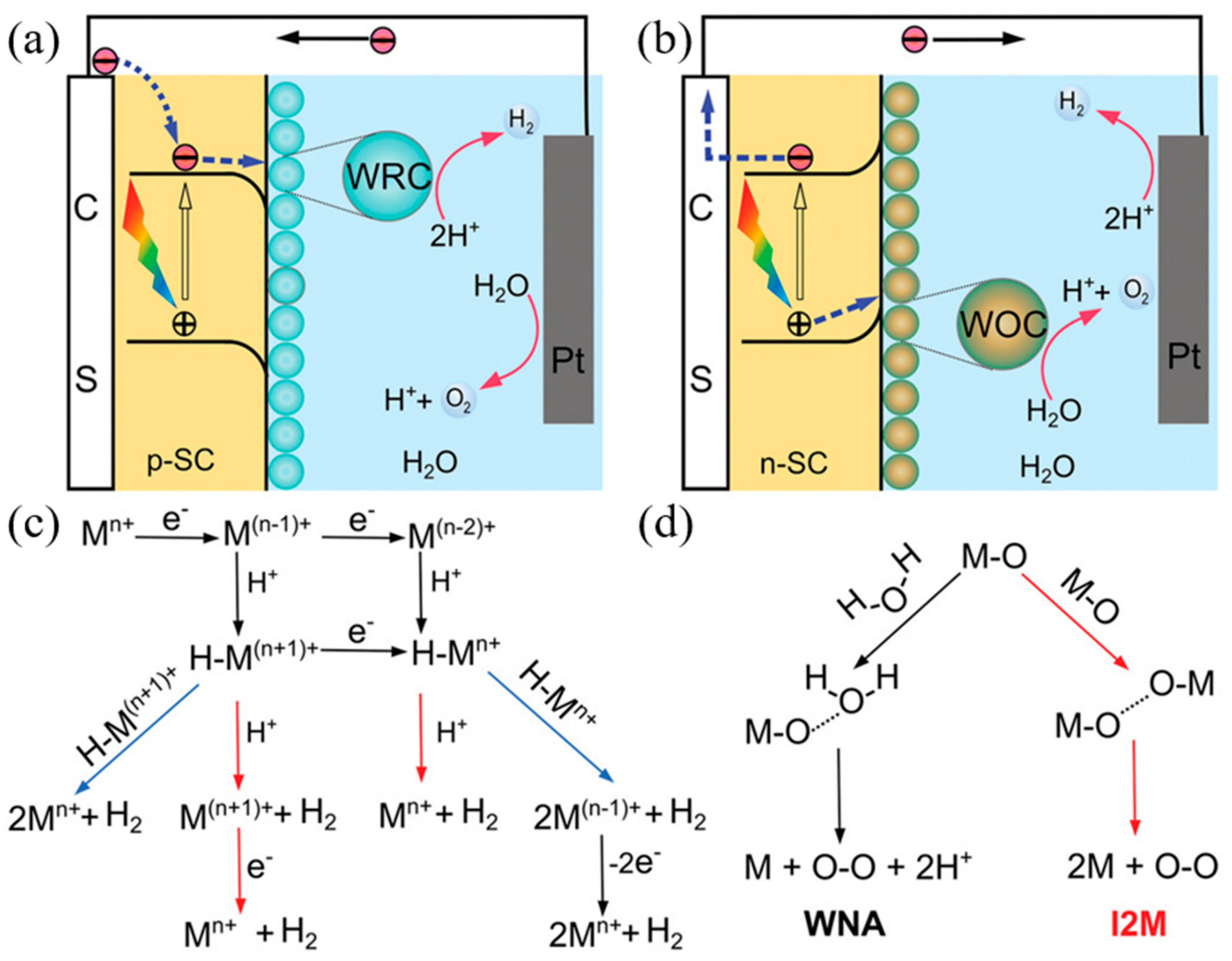
The mechanism by which photoelectrochemical water splitting occurs is shown in Figure 2. Minority carriers generated by semiconductor light absorption are induced into the solution by the electric field at the junction. The electrons and holes generated by the semiconductor are transferred to the molecular catalyst to induce the OER and HER reactions, where, typically, p-type semiconductors are used for water reduction and n-type semiconductors are used for water oxidation. Water reduction is caused by one or two electron steps at the metal center Mn+, which is followed by the reduction of Mn+ and, subsequently, followed by protonation, to give an intermediate hydride. Monometallic and bimetallic pathways occur independently or in parallel, and depend on the catalyst properties, its reduction potential, pKa for deprotonation, and pH. In water oxidation, O–O-forming mechanisms are induced by the interaction between two M–O groups (I2 M) or nucleophilic attack by water (WNA). I2 M mechanisms are achieved by reductive coupling and reductive removal, or by radical coupling through inner/intramolecular pathways. In the WNA mechanism, when the M–O is sufficiently electrophilic, the water molecules attack the M–O to form O–O bonding [61,62,63].

2.3. Mechanism of Perovskite PEC Cells

The perovskite photoelectrochemical cell consists of a perovskite light absorption layer, an electron transporting layer, and a hole transporting layer (HTL) to extract the generated electron and hole, and a passivation layer to prevent perovskite degradation in aqueous solution. A simplified working principle of the device may be described as follows: when the light falls on the device, the perovskite layer absorbs the light and generates excitons. The electron and hole pairs (EHPs) are created by the thermal energy, which is diffused and separated through the electron and hole transporting layer, respectively [64]. The performance of the perovskite-based device is influenced by the diffusion length, lifetime, and mobility of the generated carriers. The diffusion length of the perovskite depends on the qualities such as the crystallinity and grain size of the perovskite film, indicating that the diffusion length varies based on the perovskite preparation method. In the case of MAPbI3, as the diffusion length of the hole is longer than that of the electron, mesoporous TiO2 is used to compensate for this short electron diffusion length. Furthermore, performance is improved when the injected charge mobility is fast. Therefore, designing the charge transporting materials and thickness in consideration of the diffusion length and mobility of the charge is one way to improve performance [9,65,66].
The basic function of the electron transporting layer is to enhance the transport of photo-generated electrons through electron-selective contact with the perovskite layer and to prevent hole injection, so as to improve carrier separation and reduce recombination. Generally, TiO2, ZnO, [6,6]-phenyl-C61-butyric acid methyl ester (PCBM), etc. are used as electron transporting materials. Though TiO2 is the most commonly used inorganic electron transporting layer (ETL) material and its electron injection rate is very fast, it has limitations, as recombination occurs due to low electron mobility [67,68,69]. While ZnO has higher electron mobility than TiO2 (Bulk mobility: 205–300 cm2 V−1 s−1), its chemical instability is a drawback [70,71]. PCBM is a conductive polymer material with low photocurrent hysteresis and high short circuit current density. PCBM plays a critical role in improving the quality of the light-absorbing layer by filling the pinholes and vacancies between perovskite grains, resulting in a film with large grains and fewer grain boundaries [72,73,74].
The main function of the hole transporting layer is to improve electron-hole pairs separation by collecting and transporting the generated hole from the perovskite layer. The material used for the hole transporting layer is spiro-OMeTAD, poly (3,4-ethylene dioxythiophene) polystyrene sulfonate (PEDOT:PSS), and CuI. Although Spiro-OMeTAD is one of the best performing HTL materials, its cost can be an impediment, and it is also a small molecule substance which diffuses well into perovskite [75,76]. PEDOT:PSS also exhibits good performance and is a conductive polymer material like PCBM. Alternatively, while CuI has about five times the hole mobility of spiro-OMeTAD and a relatively large particle size, signifying that it does not readily diffuse into the perovskite layer, its shortcomings are that the surface is rough and it is not well bonded with perovskite due to the large particles [77,78].
Perovskite-based device configuration is derived from the dye-sensitized solar cell, and is classified into two types. One of them comprises the transparent conductive substrate coated with the electron transporting material (mesoporous/planar n-type material) under the perovskite layer and hole transporting layer (p-type material) deposited on the perovskite layer. This configuration, which is called n–i–p type, strives for an oxygen evolution reaction. In n–i–p type devices, electron-hole pairs (EHPs) generated in the perovskite layer are transported by the electron transporting material to the transparent conductive oxide (TCO) substrate, and through the hole transporting material, the holes are transported to the metal electrode (Figure 3a). Holes that reach the metal electrode through this mechanism react with oxygen ions to produce oxygen. The other common configuration is inverted compared to the former, and the transparent conductive substrate is coated with the hole transporting material, followed by the perovskite layer and electron transporting layer. This configuration, which is called p–i–n type, strives for a hydrogen evolution reaction. In the p–i–n type perovskite photoelectrochemical cell, a hydrogen evolution reaction occurs by moving electron-hole pairs (EHPs) in a converse mechanism to that of n–i–p type perovskite PEC devices. The EHPs generated in the perovskite layer are transported by the hole transporting material to the TCO substrate, and through the electron transporting material, the electrons are transported to the metal electrode (Figure 3b). The electrons are transported to the metal electrode to produce hydrogen through the reaction with the electrolyte.

3. Recent Progress on Perovskite-based Photoelectrochemical Cells

3.1. n–i–p Configuration Perovskite-Based PEC Cell for Oxygen Evolution

As described above, n–i–p configuration, perovskite-based PEC cells strive for oxygen evolution by transporting the holes generated in the perovskite layer to the top metal electrode through the hole transporting layer. In the planar type, compact-TiO2 is mainly used as an electron transporting layer, which functions as a means of hole blocking to reduce recombination as well as electron transport. In the mesoporous type, mesoporous TiO2 or Al2O3 is deposited onto the compact TiO2 to facilitate the formation of the perovskite film.
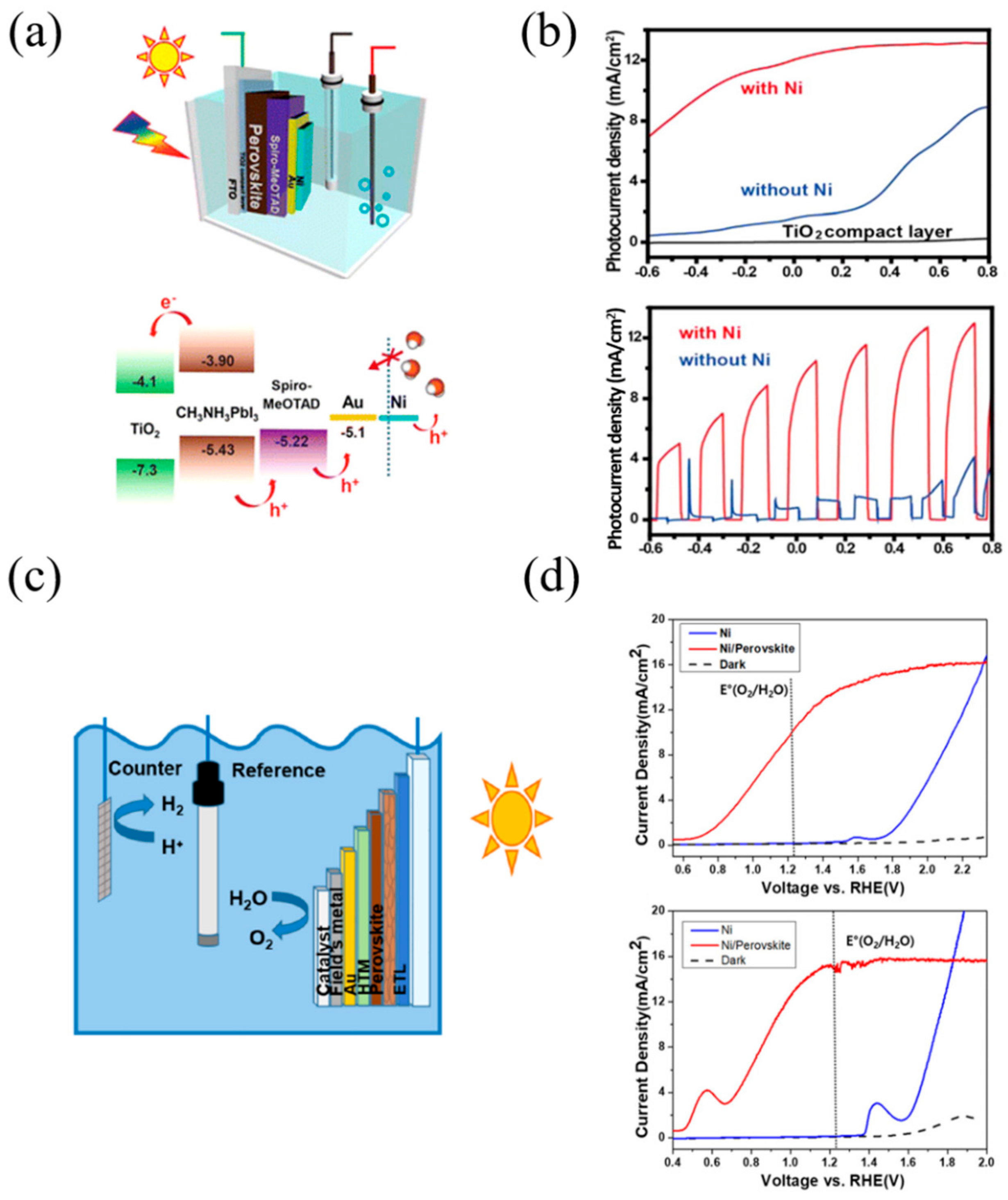
Da et al. [79] designed a perovskite photoanode device with an FTO/TiO2/CH3NH3PbI3/Spiro-OMeTAD/Au/Ni configuration (Figure 4a). The perovskite layer was deposited by a one-step method using anti-solvent, and the device consisted of an approximately 50 nm thickness of compact TiO2 layer, 220–250 nm thickness of perovskite layer for absorbing light, 250 nm thickness of a spiro-OMeTAD layer, and 80 nm and 8 nm thickness of Au and Ni layer, respectively. The holes generated in the perovskite layer are transferred to the Au/Ni layer through spiro-OMeTAD, and are used for the oxygen evolution reaction. The top Ni layer not only prevents electrolyte from penetrating into the perovskite layer, but also acts as an effective oxidation catalyst. The perovskite photoanode with an ultrathin Ni layer has a high photocurrent density and high stability in alkaline solution. Current-voltage (J-V) tests were performed for the photovoltaic performance, and the device presented the following performance: open-circuit voltages (Voc) of ~0.95 V; short-circuit current density (Jsc) of ~19.0 mA/cm2; and a fill factor (FF) of ~0.59. Perovskite-based photoanodes with and without a Ni layer were compared by PEC measurement using the three-electrode system. The PEC measurement confirmed the photocurrent of the photoanode with Ni layer enhancement at overall voltage ranges (the photocurrent density was more than 10 mA/cm2 at 0 V vs. Ag/AgCl). This confirms that the Ni layer is not only the passivation layer, but also an efficient catalyst (see Figure 4b).
Nam et al. [80] designed a perovskite photoanode device with a FTO/TiO2/CH3NH3PbI3/Spiro-OMeTAD/Au/Field’s metal/Ni configuration (Figure 4c). The device could perform ultrastable solar water splitting, even in a strong alkaline solution, through the deposition of the eutectic Field’s metal (with a eutectic alloy of Bi and Sn, and a low melting point of 62 °C) using a versatile mold-cast and lift-off process. Mold-casting and lift-off processes enable metal encapsulation with precise diameters and thicknesses, the creation of a smooth electrode surface, and ease of additional functional layer deposition. Through the current-voltage (J-V) test, the device presented the following performance: open-circuit voltages (Voc) of 0.98 V; a short-circuit current density (Jsc) of 21 mA/cm2; a fill factor (FF) of 0.78; and a power conversion efficiency of 15.6%. Since Field’s metal does not act as a catalyst for oxidation, Ni was deposited as an oxidation catalyst on Field’s metal through electrodeposition. The thin Ni film (~10 μm) also prevents the corrosion of Field’s metals, and acts as a catalyst in strong alkaline solutions. The performance of the photoanode was tested in a three-electrode system. At pHs similar to neutral, photoelectrolysis was performed under acidic or alkaline conditions, because the electrode surface pH gradient and electrode kinetics were slower when under acidic or alkaline solutions. As a result of the fast electrode kinetics and the smaller pH gradient in the alkaline solution, the current rises more rapidly in alkaline than in neutral. Overpotential was measured at 0.915 V and 0.519 V for neutral and alkaline, respectively (Figure 4d). The photocurrent of the perovskite photoelectrode becomes saturated at the positive potential region, which is essentially limited by the incident light intensity (the saturation current of 16 mA/cm2 at 0.7 sun).
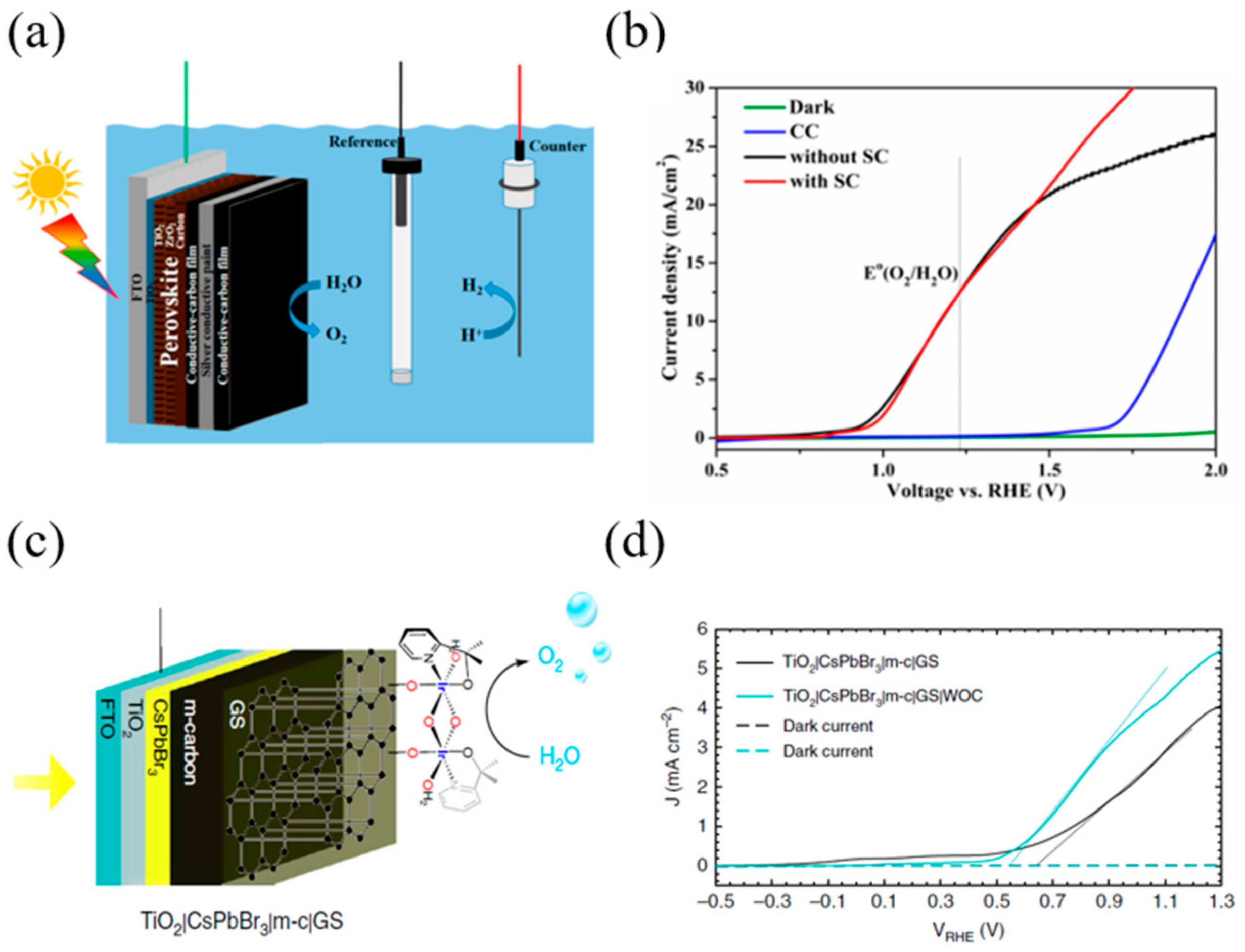
Tao et al. [81] designed a perovskite photoanode device using a commercial conductive carbon paste (CC) and conductive silver paste (SC) as a hole transporting layer and passivation layer, respectively. Perovskite was used as a mixed-cation perovskite (5-AVA)x(MA)1−xPbI3 (Figure 5a). It was observed that 5-aminovaleric acid (5-AVA) cation facilitates perovskite crystal formation in the mesoporous oxide host, resulting in better surface contact with TiO2 and low defect concentrations. Conductive carbon paste (CC) and conductive silver (SC) possess waterproof and hole transporting characteristics. The CC paste layer has a bifunctional characteristic that plays a role in hole extraction and in collection, as its work function is similar to gold. The SC paste layer creates a conductive interface with low resistance between the two CC paste layers, which allows the holes to move more freely. The photogenerated holes from the perovskite layer arrive at the top CC layer through the CC layer and the SC layer, and react with the electrolyte to produce an oxygen evolution reaction. The junction of the two conductive layers with different morphologies protects the underlying perovskite layer entirely, ensuring that the perovskite photoanode has superior performance and stability. A perovskite photoanode PEC test was performed using a three-electrode system; the photocurrent density was approximately 12.4 mA/cm2 at 1.23 V (vs. RHE). In order to examine the effect of the SC layer, the test was performed with and without the SC layer (see Figure 5b). Oxygen production through the PEC test was measured by gas chromatography, and the faradaic efficiency of the oxygen evolution of the Photoanode was calculated to be over 80%. This indicates that the increase in photocurrent is the result of oxygen production. The applied bias photon-to-current efficiency (ABPE) through the J-V curve with and without SC was shown to be up to 0.85 and 0.87, respectively. Photoanode devices using conductive carbon pastes do not require complex catalyst deposition processes, and offer superior stability using cheap carbon paste materials.
Poli et al. [82] designed a photoanode that could operate at a wide pH range (2–13) using CsPbBr3 perovskite material and a commercial thermal graphite sheet (Figure 5c). The combined layer of 20 µm thick mesoporous carbon (m-c) and commercial hydrophobic graphite sheet (GS) prevented the perovskite layer from being degraded by water. The device could operate in the 2–13 pH range, and the photocurrent at 1.23 VRHE showed close to 3.8 mA/cm2 in acidic solution. In addition, the device showed more than 2 mA/cm2 current for 30 h and excellent stability in an alkaline electrolyte solution (pH 12.5). By depositing the Ir-based water oxidation catalyst (WOC) on the GS surface, the onset potential of the photoanode was reduced to 100 mV. With and without WOC, samples show similar open-circuit potential and ΔVph at equilibrium, and similar water oxidation photocurrent at 1.23 VRHE (see Figure 5d). This indicates that the presence of WOC increases the charge transfer kinetics rather than the thermodynamic effect. Finally, the faradaic efficiency for the photoelectrochemical oxygen evolution of a TiO2|CsPbBr3|m-c|GS|WOC photoanode device was calculated to be 82.3%.

3.2. p–i–n Configuration Perovskite-Based PEC Cell for Hydrogen Evolution

As described above, the p–i–n configuration, perovskite-based PEC cell strives for hydrogen evolution by the opposite mechanism of the n–i–p configuration, transporting electrons generated in the perovskite layer to the top metal electrode through the electron transporting layer. In the p–i–n configuration, the electron transporting material cannot use materials requiring high heat treatment such as TiO2, and therefore, primarily uses organic materials such as PCBM.
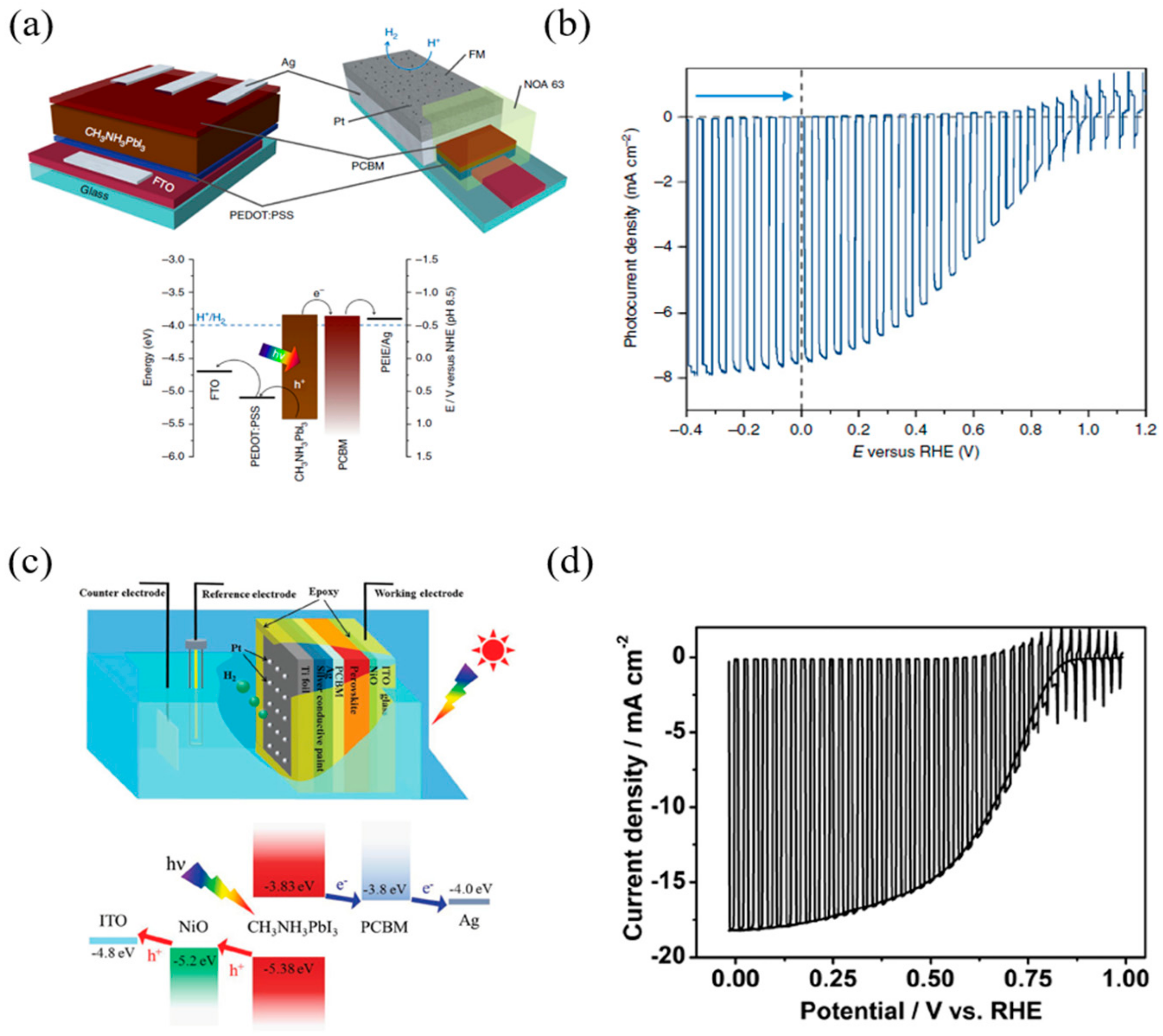
Crespo-Quesada et al. [83] devised a stable perovskite-based photocathode using Field’s metal (a fusible In–Bi–Sn alloy) for the passivation layer (Figure 6a). The perovskite photocathode device had a thickness of 40 nm of PEDOT: PSS, a 300 nm thickness of MAPbI3, a 40 nm thickness of PCBM, and a 100 nm thickness of Ag. Field’s metal encapsulation was performed for two purposes: to prevent perovskite degradation from water, and to effectively transport the photogenerated electron. Perovskite-based photocathode photoelectrochemical tests showed that the average photocurrent was −6.9 ± 1.8 mA/cm2 at 0 V (vs. RHE), and the average onset potential was 0.95 ± 0.03 VRHE (Figure 6b). Finally, the faradaic efficiency for the hydrogen evolution of the photocathode was calculated to be 95.1 ± 2.2%.
Zhang et al. [84] proposed a perovskite-based photocathode using titanium foil for the p–i–n type structure. The device used NiO as a hole transporting material, PCBM as an electron transporting material, and Ti foil as a passivation layer (see Figure 6c). Titanium is inexpensive, robust, and chemically stable. However, as titanium is difficult to use as an HER catalyst, additional Pt sputtering was performed on the Ti foil. The results of the photovoltaic performance test of the device exhibited a short-circuit current density (Jsc) of −20.38 mA/cm2, an open-circuit voltage (Voc) of 1.09 V, a fill factor (FF) of 72.9%, and a power conversion efficiency (PCE) of 16.1%, and the external quantum efficiency (EQE, 390–720 nm range) was calculated to be 70%. The PEC performance measurement of the device indicated a photocurrent of −18 mA/cm2 at 0 VRHE and an onset potential of 0.95 VRHE, and the ideal ratiometric power-saved efficiency was calculated to be 7.63% (see Figure 6d). The onset potential and photocurrent values of the photocathode through the PEC test were similar to those of Voc and Jsc, demonstrating that the benefits of perovskite PV devices can be obtained in PEC devices. Finally, the faradaic efficiency for hydrogen evolution of perovskite-based photocathode devices was calculated to be close to 100%.
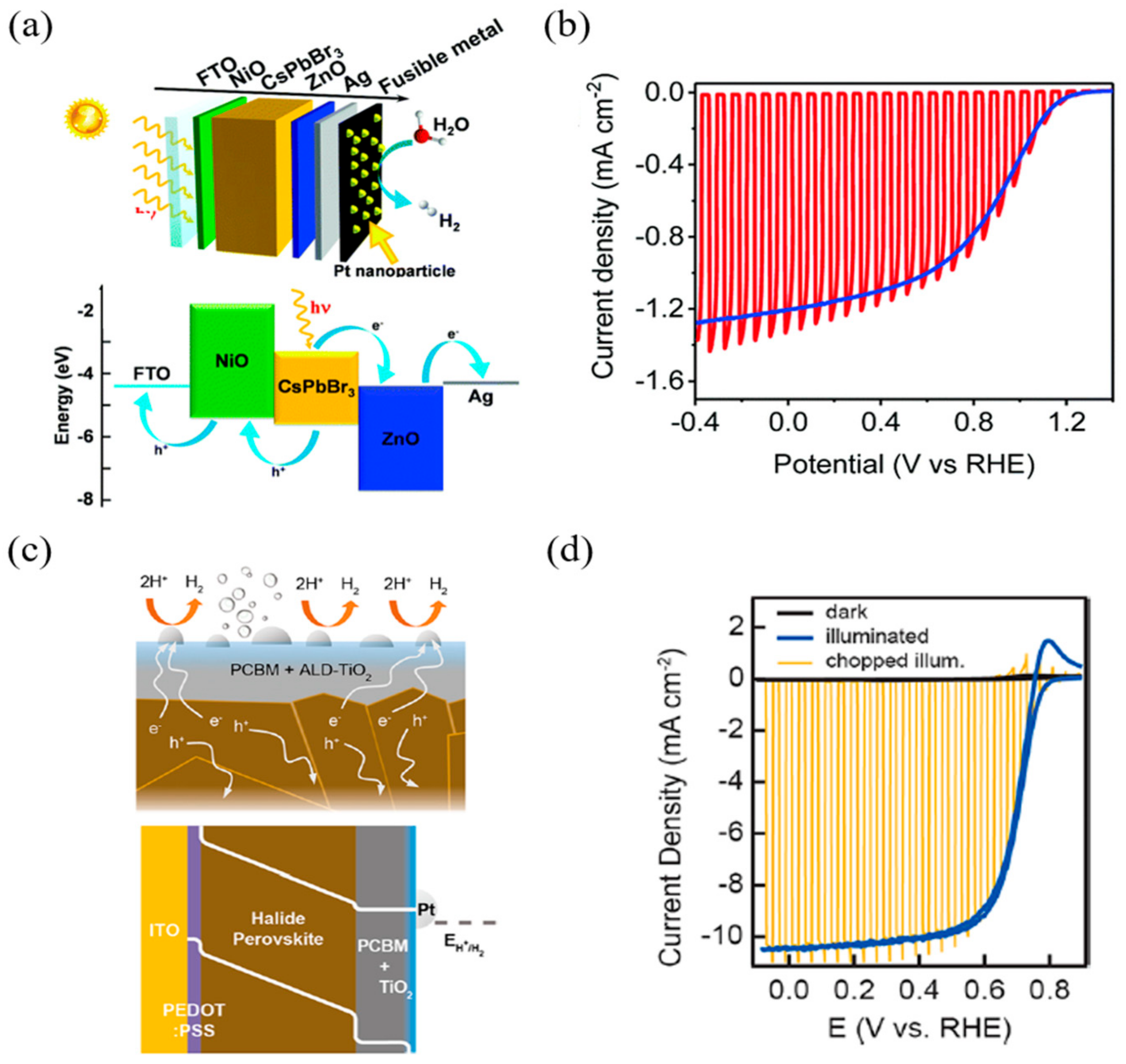
Gao et al. [85] designed a perovskite photocathode using bulk material-based encapsulation (see Figure 7a). To thoroughly prevent the penetration of water into the perovskite layer, the device was encapsulated using a fusible In–Bi–Sn alloy, and silver was deposited between the passivation layer and the electron transporting layer (ZnO) to improve the electrical conductivity. Finally, Pt was deposited on fusible alloys as a catalyst for hydrogen evolution reactions. The results of the photovoltaic performance test of the device exhibited a short-circuit current density (Jsc) of −2.50 mA/cm2, an open-circuit voltage (Voc) of 1.37 V, a fill factor (FF) of 55.8%, and a power conversion efficiency (PCE) of 1.91% (Figure 7b). The PEC performance measurement of the device exhibited a photocurrent of 1.2 mA/cm2 at 0 VRHE under AM 1.5 G simulated sunlight conditions (100 mW/cm2), an onset potential of 1.16 VRHE, and a maximum half-cell solar to hydrogen efficiency (HC-STH) of 0.64%. Finally, the faradaic efficiency of the hydrogen evolution of the CsPbBr3-based photocathode was calculated to be over 90%.
Kim et al. [86] designed a photocathode using a triple-cation formulation of halide perovskite and a hybrid electron transporting layer (see Figure 7c). Triple-cation perovskite exhibits improved thermal stability and exceptional optical and electrical performance compared to simple methylammonium lead iodide, which, for its part, is expected to improve the overall photoelectrochemical performance; additionally supplemental Cesium (Cs) assists in uniform perovskite film formation. The organic component of ETL, PC61BM, shows exceptional electron-transporting and low recombination compared to TiO2. Moreover, device stability was secured by depositing TiO2 through atomic layer deposition. PEC performance measurement of the device exhibited a photocurrent of 10.5 mA/cm2 at 0 VRHE under AM 0.5 G simulated sunlight conditions, the onset potential was more positive than that observed for dark HER under the same conditions, and the fill factor was calculated to be 68.87% (see Figure 7d). This large FF appears to be the result of the fast charge transporting and recombination inhibition of hybrid ETLs. The above cases are summarized in the Table 1.

4. Stability Issues of Perovskite PEC Cells

4.1. Degradation of Perovskite Material by Moisture

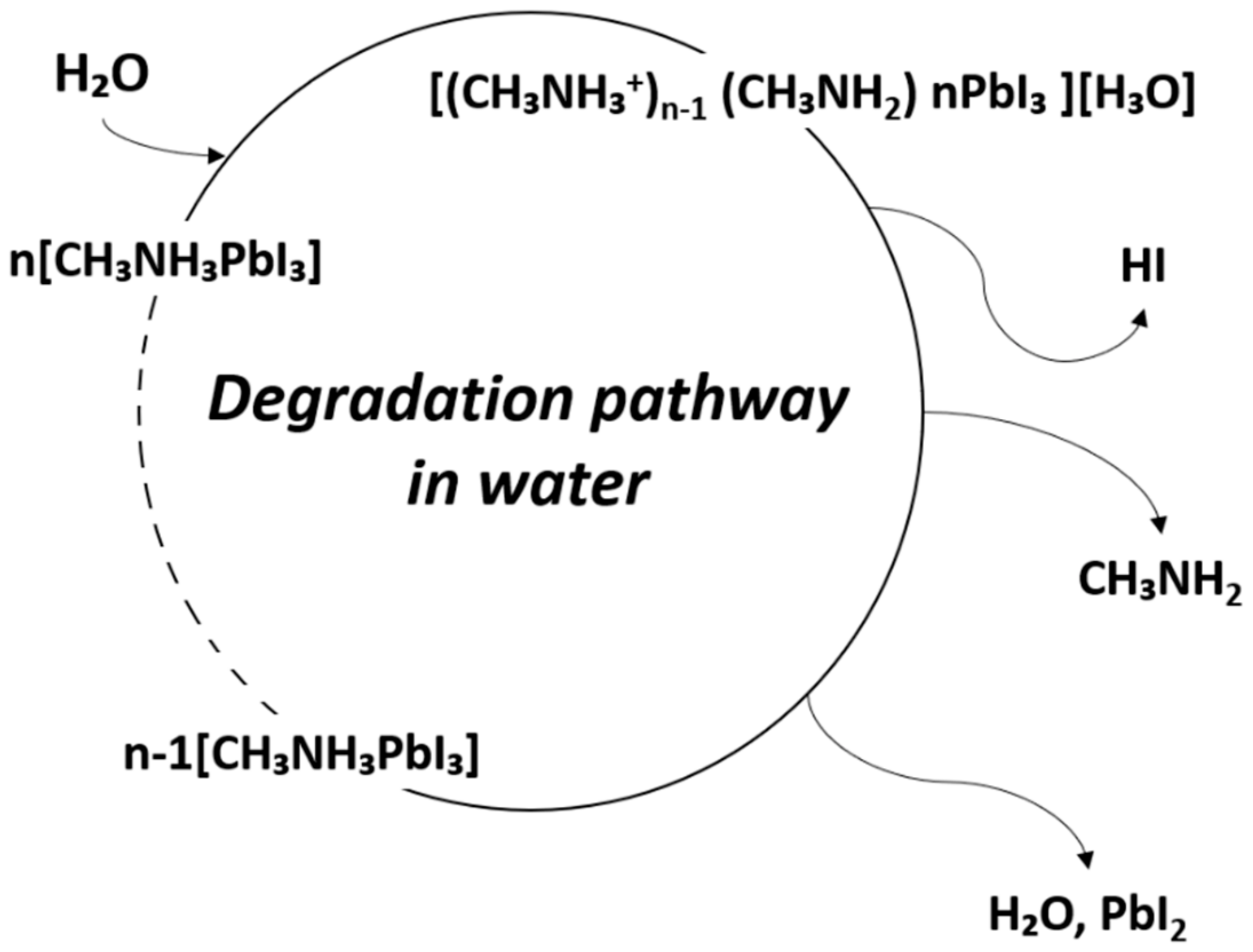
The instability of metal-organic halide perovskite in humid environments is the biggest obstacle to its applicability in devices, given its other notable properties. The perovskite film is highly sensitive to the presence of water, which affects the stability of devices in which it is used. In addition, perovskite can degrade at the polar solvent. The degradation of perovskite has been reported due to the highly hygroscopic property of amine salts [89]. Due to the high hygroscopicity of organic compounds, when perovskite is exposed to water, organic compounds detach from the crystal structure, and the perovskite crystallinity is changed. This results in changes in the optical and electrical properties causing variations in the performance of perovskite-based devices [90]. In other words, due to the degradation of perovskite by water, the noteworthy optical and electrical properties of perovskite are lost, and the device performance is degraded. The degradation mechanism due to moisture is shown in Figure 8 [91].
CH₃NH₃PbI₃ (s) → CH₃NH₃PbI (aq) + PbI2 (s)
CH₃NH₃PbI (aq) → CH₃NH2 (aq) + HI (aq)
4HI (aq) + O2 (g) → 2I2 (s) + 2H2O (l)
2HI (aq) → H2 (g) + I2 (s)
In fact, perovskite readily transforms to monohydrate phase MAPbI3∙H2O in moderate humidity (RH < 60%), and to dihydrate phase (MA)4PbI6∙2H2O in high humidity (RH > 80%). This can be explained by the fact that the hydrogen bonding interaction between the lead iodide framework and organic MA+ cations is weakened by hydration. As a result, MA is diffused and detached from PbI6 octahedra, whereby MAPbI3 degrades rapidly. The activation barrier for vacancy-mediated MA+ migration is reduced from 1.18 eV for MAPbI3 to 0.38 eV for water-intercalation, and 1.14 eV for the monohydrated phase. When MAPbI3 is exposed to an aqueous solution, it degrades to PbI2 precipitate, iodide anion, and methylammonium cation [92,93].
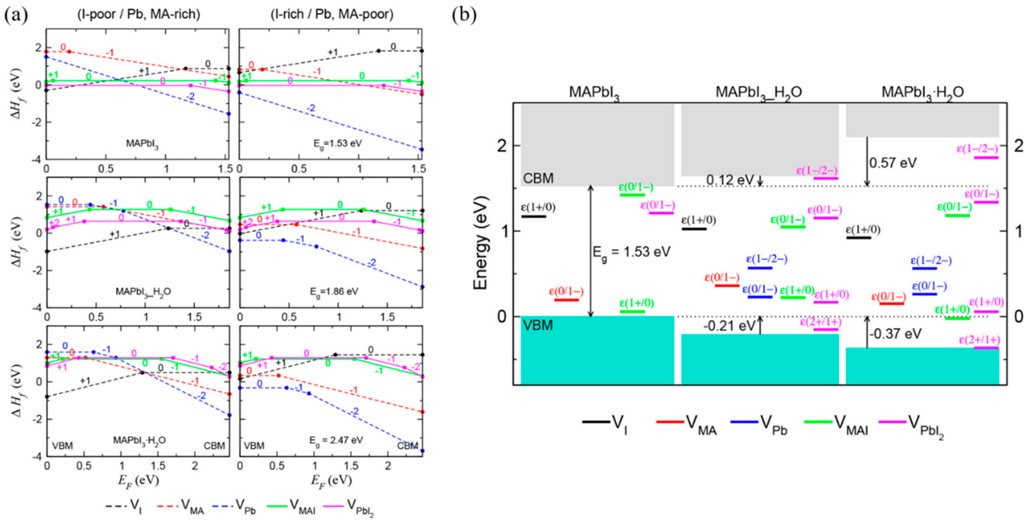
Kye et al. [92] identified perovskite degradation in water through a point defect process by density-functional theory (DFT) calculation. Due to the kinetic barrier for I, ion migration becomes very low when hydrated, and VPbI2 formation occurs spontaneously. In the hydrous compound, the formation of VI and VMA is preferred to the formation of VMAI, so that during the MAPbI3 degradation, the formation of I2 or CH3NH2 or HI is higher than that of MAI (Figure 9a). Unlike bulk MAPbI3, all vacancy defects form deep transition levels through electrostatic interaction with water molecules (Figure 9b).
Several methods have been identified to reduce the degradation of perovskite solar cells (PSC) by water. The first is to add a thin blocking layer like Al2O3 between the perovskite and hole transporting material (HTM) [94,95]. The second is to use moisture blocking HTM. The last method is to use hydrophobic carbon electrode [96,97].

4.2. Passivation Strategies for Improving Stability

Perovskite-based photoelectrochemical devices require a direct junction between the electrolyte and the device. However, due to the tendency of the perovskite material to degrade when in contact water, which is a vulnerability, passivation technology to protect it is essential. There are two fundamental methods of passivation: (i) bulk material-based encapsulation, and (ii) compact material-based passivation. Passivation using bulk materials prevents moisture from entering the device, primarily by using titanium foil or Field’s metal with a low melting point.
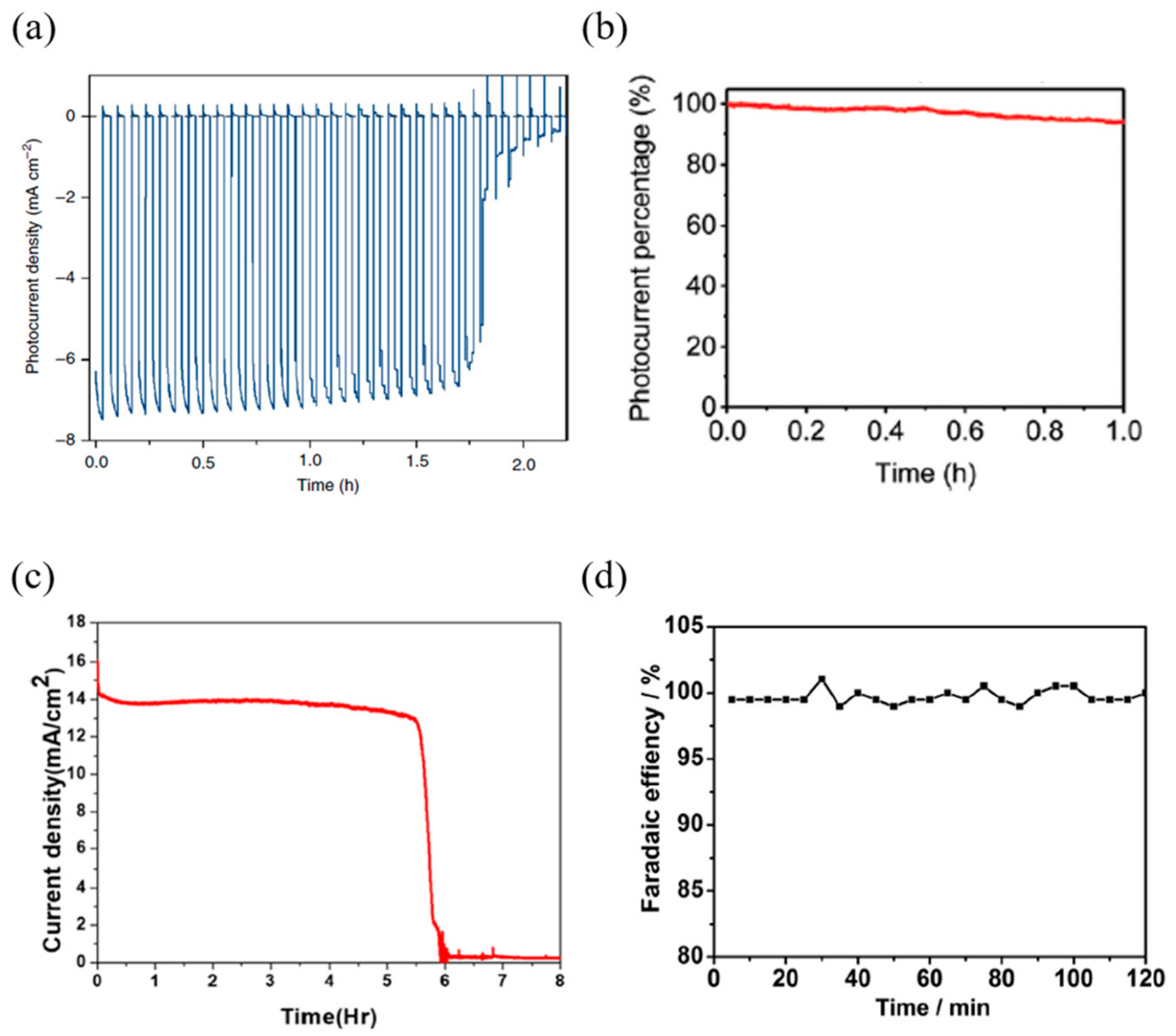
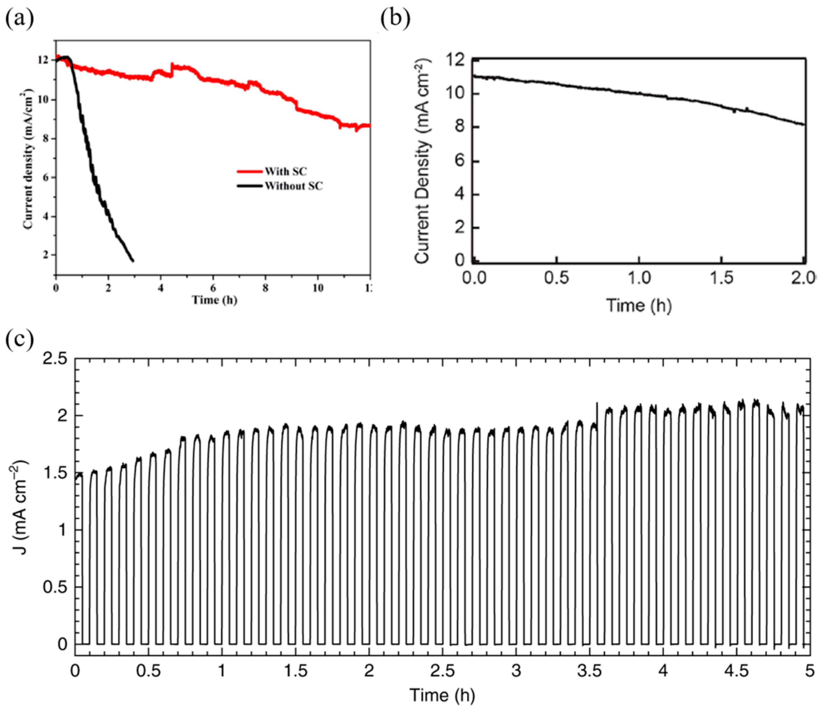
Crespo-Quesada et al. [83] devised a perovskite-based photocathode employing Field’s metal, which showed a performance decrease of 80% of the initial photocurrent after 1.5 h, and then showed a sharp photocurrent reduction in 0.1 M borate (see Figure 10a). Gao et al. [85] also devised a photocathode for hydrogen production with Field’s metal passivation; the device maintained a stable 94% photocurrent after 1 h under AM 1.5 G simulated sunlight conditions (see Figure 10b). Nam et al. [80] devised a perovskite-based photoanode for oxygen production with the Field’s metal passivation; the device showed superior stability while maintaining an initial photocurrent of 93% after 5 h under AM 0.7 G sun and KOH solution (see Figure 10c). Zhang et al. [84] designed a photocathode device with titanium foil passivation, which showed stable characteristics for 12 h, and notably, exhibited the same hydrogen evolution Faradaic efficiency for 2 h in a 0.5 M H2SO4 solution (see Figure 10d).
The second method, i.e., the passivation method using compact materials, prevents water from entering the perovskite layer by means of thin surface treatment. Although Da et al. [79] improved the stability of the photoanode by sputtering ultrathin Ni layers (8 nm), the device showed 56% photocurrent after 100 s through a PEC test in alkaline solution, showing a performance degradation in a short period time. Tao et al. [81] designed a photoanode with both high stability and high performance using conductive carbon paste and silver paste. Carbon paste was deposited directly onto the perovskite layer to enable hole transporting and passivation. However, due to the low stability of the single carbon paste, a combination of carbon paste and silver paste was used to enhance stability, which, in turn, made it possible to maintain more than 70% photocurrent after 12 h of operation (see Figure 11a). Kim et al. [86] improved the stability of the photocathode device by forming a thin, compact layer through titanium atomic layer deposition (ALD); the device showed 75% photocurrent (10.5 mA/cm2) in a strong acid solution (H2SO4), even after 2 h (see Figure 11b). Finally, Poli et al. [82] created a highly-stable photoanode through passivation using a mesoporous carbon and graphite sheet; the device was stable for 5 h in a pH 12.5 solution, and the photocurrent was increased from 1.5 mA/cm2 to 2 mA/cm2. The device also showed a lifetime of 34 h in alkaline electrolyte, 23 h in a near-neutral solution, and 7.8 h in an acidic solution (see Figure 11c).

4.3. Enhanced Stability through the Introduction of Inorganic Perovskites

So far, as the main topic, metal-organic halides have been discussed as perovskite materials composed of organic materials and halides such as bromine and iodine. As mentioned above, they have some key advantages in the manufacturing process of the perovskite layer, because they can be produced at low temperatures, though it is well-known that metal-organic halides are vulnerable to damage from moisture. In contrast, inorganic perovskite materials require high temperatures for synthesis that cause some difficulties in the manufacturing process, but they are more sustainable in the atmosphere, comparatively. Therefore, some researchers are mainly focusing on inorganic perovskite-based PEC systems.
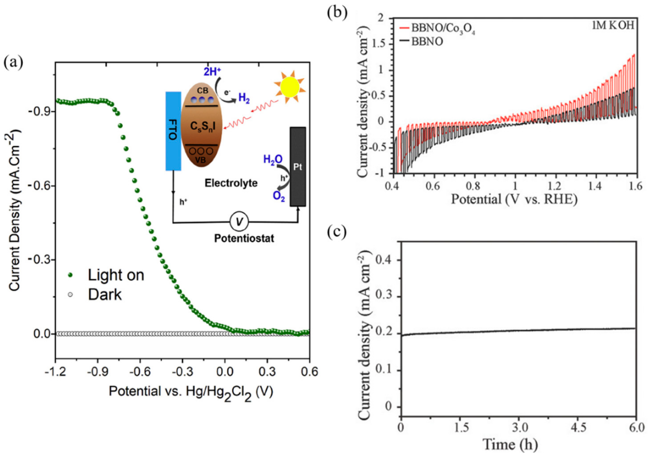
Dang et al. [98] synthesized an inorganic perovskite Cs2SnI6 film through a solution process. Cesium tin iodide generally has an orthorhombic structure at room temperature, and this material demonstrates phase transitions under synthesis conditions (ambient air, annealing temperature, synthesis method). The phase transition of the cubic structure has high active site density and a slow rate of intraband relaxation of the excitonic state, which is expected to improve the performance of the PEC system. Here, Cs2SnI6 was synthesized with a uniform morphology of cubic structures through annealing at 170 °C for 8 h. PEC cells were prepared by synthesizing Cs2SnI6 on an FTO substrate using a solution-processed approach. The PEC test was conducted in 0.3 M NaCl, and showed a photocurrent density of 0.92 mA/cm2 with an energy conversion efficiency of 0.54% at −0.8 V (Hg/Hg2Cl2) (Figure 12a).
Weng et al. [99] proposed an improved PEC performance by reducing the bandgap through the bandgap engineering of Barium Bismuth Niobate Double perovskite (BBNO) to enhance the absorption of visible light. The results suggest that Bi-rich, Nb-poor off-stoichiometry could reduce the bandgap using density-functional theory (DFT) calculations. In BBNO crystals, the valance band maximum (VBM) is determined by the Bi 6s lone pair orbital (Bi3+), and the conduction band minimum (CBM) is determined by the unoccupied Bi 6s orbital (Bi5+). In addition, strong antibonding of Bi 6s and O 2p orbital shifts the VBM to higher energy states. On the other hand, because the unoccupied Bi 6s orbital is located at the much lower energy level than the unoccupied Nb 4d and Bi 6p orbitals, the bandgap gets reduced when both Bi3+ and Bi5+ cations coexist. Ba2Bi1.4Nb0.6O6 was confirmed to have the lowest VBM by DFT calculation. Therefore, in the Ba2Bi1.4Nb0.6O6 system, the hole would be easily transported to the electrolyte; therefore, a PEC oxidation test was conducted. Thus, the Ba2Bi1.4Nb0.6O6 photoanode exhibited 0.2 mA/cm2 at 1.23 VRHE and 0.4 mA/cm2 photocurrent density at 1.23 VRHE when the Co3O4 nanoparticle catalyst was deposited (see Figure 12b). Also, it showed a constant photocurrent density for 6 h and excellent stability without any changes in the x-ray diffraction (XRD) patterns (Figure 12c).
In addition, Bin et al. [100] designed a PEC cell with a hybrid tandem structure using an organic photovoltaic, perovskite solar cell, and graphene. The bottom cell consists of polymer with a wide bandgap, while the top cell possesses a MAPBI3 perovskite-based cell separated by a layer of graphene. Therefore, the hybrid tandem perovskite solar cell showed a short-circuit voltage (Jsc) of 8.73 mA/cm2, an open-circuit voltage (Voc) 1.86 V, a fill factor (FF) 0.72, and a power conversion efficiency (PCE) of 11.28%. The PEC test showed a photocurrent of ~7.25 mA/cm2 and 9.02% solar-to-hydrogen efficiency.

5. Conclusions

In summary, this review discusses the advancements of perovskite-based photoelectrochemical cells for generating renewable energy. As a result of their exceptional electrical and optical properties, the application of perovskite materials to photoelectrochemical reactions aims to enhance performance. However, it is essential to improve the stability of perovskite by passivation due to the requirement of an aqueous solution. Therefore, research into the development of stable, perovskite-based photoelectrochemical cells which overcome vulnerability to aqueous solutions has been pursued. In order to minimize degradation by encapsulating the device using bulk material, Crespo-Quesada et al. [83], Gao et al. [85], and Nam et al. [80] devised cells using Field’s metal as a passivation layer, and Zhang et al. [84] devised a cell using titanium foil as a passivation layer. Conversely, as a method of using compact material deposition, Da et al. [79] formed a passivation layer by sputtering ultrathin Ni layers (8 nm), and Tao et al. [81] devised a cell using a passivation layer by depositing conductive carbon and silver paste through the doctor blade method. Kim et al. [86] formed a passivation layer through the ALD process, and Poli et al. [82] devised a stable perovskite-based PEC device using mesoporous carbon and a graphite sheet. Nevertheless, the use of perovskite as a PEC requires improved stability through the development of passivation technology, because of its low stability when compared to other PEC materials. Therefore, for the advancement of perovskite-based PEC devices, continuous research into passivation technology for stable PEC reactions, as well as research into performance improvement, is essential. Perovskite-based PEC devices with long-term stability and exceptional optical and electrical properties are expected to enable effective and environment-friendly chemical energy production through PEC reactions.

Author Contributions

Conceptualization, D.K., and D.-K.L.; investigation, D.K.; data curation, D.K., D.-K.L., and S.M.K.; writing—original draft preparation, D.K., and D.-K.L.; writing—review and editing, S.M.K., and D.-K.L.; supervision, W.P., and U.S. All authors have read and agreed to the published version of the manuscript.

Funding

This research was funded by the Basic Science Research Program through the National Research 309 Foundation of Korea funded by the Ministry of Science and ICR, grant number 2018R1A5A1025224 and the National Research Foundation of Korea (NRF) funded by the Ministry of Science grant number 2018R1C1B6001267.

Acknowledgments

The work done by W.P. is supported by Sookmyung Women’s University, grant number 1-1903-2006.

Conflicts of Interest

The authors declare no conflict of interest.

References

  1. UNFCCC. The Paris Agreement. In Proceedings of the Paris Climate Change Conference, COP 21, Paris, France, 29 January 2016. [Google Scholar]
  2. Sim, U.; Moon, J.; An, J.; Kang, J.H.; Jerng, S.E.; Moon, J.; Cho, S.-P.; Hong, B.H.; Nam, K.T. N-Doped Graphene Quantum Sheets on Silicon Nanowire Photocathodes for Hydrogen Production. Energy Environ. Sci. 2015, 8, 1329–1338. [Google Scholar] [CrossRef]
  3. Khaselev, O.; Turner, J.A. A Monolithic Photovoltaic-Photoelectrochemical Device for Hydrogen Production Via Water Splitting. Science 1998, 280, 425–427. [Google Scholar] [CrossRef] [PubMed]
  4. Sim, Y.; John, J.; Surendran, S.; Moon, B.; Sim, U. Efficient Photoelectrochemical Water Splitting Reaction using Electrodeposited Co3Se4 Catalyst. Appl. Sci. 2019, 9, 16. [Google Scholar] [CrossRef] [Green Version]
  5. An, T.-Y.; Surendran, S.; Kim, H.; Choe, W.-S.; Kim, J.K.; Sim, U. A Polydopamine-Mediated Biomimetic Facile Synthesis of Molybdenum Carbide-Phosphide Nanodots Encapsulated in Carbon Shell for Electrochemical Hydrogen Evolution Reaction with Long-Term Durability. Compos. Part B Eng. 2019, 175, 107071. [Google Scholar] [CrossRef]
  6. Marsen, B.; Cole, B.; Miller, E.L. Photoelectrolysis of Water Using Thin Copper Gallium Diselenide Electrodes. Sol. Energy Mater. Sol. Cells 2008, 92, 1054–1058. [Google Scholar] [CrossRef]
  7. Goodey, A.P.; Eichfeld, S.M.; Lew, K.-K.; Redwing, J.M.; Mallouk, T.E. Silicon Nanowire Array Photoelectrochemical Cells. J. Am. Chem. Soc. 2007, 129, 12344–12345. [Google Scholar] [CrossRef]
  8. Sun, J.; Zhong, D.K.; Gamelin, D.R. Composite Photoanodes for Photoelectrochemical Solar Water Splitting. Energy Environ. Sci. 2010, 3, 1252–1261. [Google Scholar] [CrossRef]
  9. Weng, B.; Grice, C.R.; Ge, J.; Poudel, T.; Deng, X.; Yan, Y. Barium Bismuth Niobate Double Perovskite/Tungsten Oxide Nanosheet Photoanode for High-Performance Photoelectrochemical Water Splitting. Adv. Energy Mater. 2018, 8, 1701655. [Google Scholar] [CrossRef]
  10. Galkowski, K.; Mitioglu, A.; Miyata, A.; Plochocka, P.; Portugall, O.; Eperon, G.E.; Wang, J.T.-W.; Stergiopoulos, T.; Stranks, S.D.; Snaith, H.J. Determination of the Exciton Binding Energy and Effective Masses for Methylammonium and Formamidinium Lead Tri-Halide Perovskite Semiconductors. Energy Environ. Sci. 2016, 9, 962–970. [Google Scholar] [CrossRef] [Green Version]
  11. Yin, W.J.; Shi, T.; Yan, Y. Unique Properties of Halide Perovskites as Possible Origins of the Superior Solar Cell Performance. Adv. Mater. 2014, 26, 4653–4658. [Google Scholar] [CrossRef]
  12. Mitzi, D.B.; Feild, C.A.; Schlesinger, Z.; Laibowitz, R.B. Transport, Optical, and Magnetic Properties of the Conducting Halide Perovskite CH3NH3SnI3. J. Solid State Chem. 1995, 114, 159–163. [Google Scholar] [CrossRef]
  13. Gharibzadeh, S.; Nejand, B.A.; Moshaii, A.; Mohammadian, N.; Alizadeh, A.H.; Mohammadpour, R.; Ahmadi, V.; Alizadeh, A. Two-Step Physical Deposition of a Compact CuI Hole-Transport Layer and the Formation of an Interfacial Species in Perovskite Solar Cells. Chem. Sus. Chem. 2016, 9, 1929–1937. [Google Scholar] [CrossRef] [PubMed]
  14. Wang, F.; Ma, J.; Xie, F.; Li, L.; Chen, J.; Fan, J.; Zhao, N. Organic Cation-Dependent Degradation Mechanism of Organotin Halide Perovskites. Adv. Funct. Mater. 2016, 26, 3417–3423. [Google Scholar] [CrossRef]
  15. Han, Y.; Meyer, S.; Dkhissi, Y.; Weber, K.; Pringle, J.M.; Bach, U.; Spiccia, L.; Cheng, Y.-B. Degradation Observations of Encapsulated Planar CH 3 NH 3 PbI 3 Perovskite Solar Cells at High Temperatures and Humidity. J. Mater. Chem. A 2015, 3, 8139–8147. [Google Scholar] [CrossRef]
  16. Sabba, D.; Kumar, M.H.; Wong, L.H.; Barber, J.; Grätzel, M.; Mathews, N. Perovskite–Hematite Tandem Cells for Efficient Overall Solar Driven Water Splitting. Nano Lett. 2015, 15, 3833–3839. [Google Scholar]
  17. Chen, Y.-S.; Manser, J.S.; Kamat, P.V. All Solution-Processed Lead Halide Perovskite-BiVO4 Tandem Assembly for Photolytic Solar Fuels Production. J. Am. Chem. Soc. 2015, 137, 974–981. [Google Scholar] [CrossRef] [Green Version]
  18. Qiu, Y.; Liu, W.; Chen, W.; Zhou, G.; Hsu, P.-C.; Zhang, R.; Liang, Z.; Fan, S.; Zhang, Y.; Cui, Y. Efficient Solar-Driven Water Splitting by Nanocone BiVO4-Perovskite Tandem Cells. Sci. Adv. 2016, 2, e1501764. [Google Scholar] [CrossRef] [Green Version]
  19. Milić, J.V.; Im, J.-H.; Kubicki, D.J.; Ummadisingu, A.; Seo, J.-Y.; Li, Y.; Ruiz-Preciado, M.A.; Dar, M.I.; Zakeeruddin, S.M.; Emsley, L.; et al. Supramolecular Engineering for Formamidinium-Based Layered 2D Perovskite Solar Cells: Structural Complexity and Dynamics Revealed by Solid-State NMR Spectroscopy. Adv. Eng. Mater. 2019, 9, 1900284. [Google Scholar] [CrossRef]
  20. Tejuca, L.G.; Fierro, J.L.G. Properties and Applications of Perovskite-Type Oxides; CRC Press: Boca Raton, FL, USA, 1992. [Google Scholar]
  21. Pena, M.A.; Fierro, J.L.G. Chemical Structures and Performance of Perovskite Oxides. Chem. Rev. 2001, 101, 1981–2018. [Google Scholar] [CrossRef]
  22. Tan, Z.-K.; Moghaddam, R.S.; Lai, M.L.; Docampo, P.; Higler, R.; Deschler, F.; Price, M.; Sadhanala, A.; Pazos, L.M.; Credgington, D. Bright Light-Emitting Diodes Based on Organometal Halide Perovskite. Nat. Nanotechnol. 2014, 9, 687. [Google Scholar] [CrossRef]
  23. Sutherland, B.R.; Sargent, E.H. Perovskite Photonic Sources. Nat. Photonics 2016, 10, 295. [Google Scholar] [CrossRef]
  24. Hu, X.; Zhang, X.; Liang, L.; Bao, J.; Li, S.; Yang, W.; Xie, Y. High-Performance Flexible Broadband Photodetector Based on Organolead Halide Perovskite. Adv. Funct. Mater. 2014, 24, 7373–7380. [Google Scholar] [CrossRef]
  25. Chen, J.; Zhou, S.; Jin, S.; Li, H.; Zhai, T. Crystal Organometal Halide Perovskites with Promising Optoelectronic Applications. J. Mater. Chem. C 2016, 4, 11–27. [Google Scholar] [CrossRef]
  26. Li, Z.; Yang, M.; Park, J.-S.; Wei, S.-H.; Berry, J.J.; Zhu, K. Stabilizing Perovskite Structures by Tuning Tolerance factor: Formation of Formamidinium and Cesium Lead Iodide Solid-State Alloys. Chem. Mater. 2015, 28, 284–292. [Google Scholar] [CrossRef]
  27. Tanaka, K.; Takahashi, T.; Ban, T.; Kondo, T.; Uchida, K.; Miura, N. Comparative Study on the Excitons in Lead-Halide-Based Perovskite-Type Crystals CH3NH3PbBr3 CH3NH3PbI3. Solid State Commun. 2003, 127, 619–623. [Google Scholar] [CrossRef]
  28. Wu, K.; Bera, A.; Ma, C.; Du, Y.; Yang, Y.; Li, L.; Wu, T. Temperature-Dependent Excitonic Photoluminescence of Hybrid Organometal Halide Perovskite Films. Phys. Chem. Chem. Phys. 2014, 16, 22476–22481. [Google Scholar] [CrossRef]
  29. Chung, I.; Song, J.-H.; Im, J.; Androulakis, J.; Malliakas, C.D.; Li, H.; Freeman, A.J.; Kenney, J.T.; Kanatzidis, M.G. CsSnI3: Semiconductor or Metal? High Electrical Conductivity and Strong Near-Infrared Photoluminescence from a Single Material. High Hole Mobility and Phase-Transitions. J. Am. Chem. Soc. 2012, 134, 8579–8587. [Google Scholar] [CrossRef]
  30. Eperon, G.E.; Stranks, S.D.; Menelaou, C.; Johnston, M.B.; Herz, L.M.; Snaith, H.J. Formamidinium Lead Trihalide: A Broadly Tunable Perovskite for Efficient Planar Heterojunction Solar Cells. Energy Environ. Sci. 2014, 7, 982–988. [Google Scholar] [CrossRef]
  31. Zhang, F.; Zhong, H.; Chen, C.; Wu, X.-G.; Hu, X.; Huang, H.; Han, J.; Zou, B.; Dong, Y. Brightly Luminescent and Color-Tunable Colloidal CH3NH3PbX3 (X = Br, I, Cl) Quantum Dots: Potential Alternatives for Display Technology. ACS Nano 2015, 9, 4533–4542. [Google Scholar] [CrossRef]
  32. Barugkin, C.; Cong, J.; Duong, T.; Rahman, S.; Nguyen, H.T.; Macdonald, D.; White, T.P.; Catchpole, K.R. Ultralow Absorption Coefficient and Temperature Dependence of Radiative Recombination of CH3NH3PbI3 Perovskite from Photoluminescence. J. Phys. Chem. Lett. 2015, 6, 767–772. [Google Scholar] [CrossRef]
  33. Alonso, M.I.; Charles, B.; Francisco-López, A.; Garriga, M.; Weller, M.T.; Goñi, A.R. Spectroscopic Ellipsometry Study of FA x MA1−x PbI3 Hybrid Perovskite Single Crystals. J. Vac. Sci. Technol. B Nanotechnol. Microelectron. Mater. Process. Meas. Phenom. 2019, 37, 062901. [Google Scholar]
  34. Green, M.A.; Ho-Baillie, A.; Snaith, H.J. The Emergence of Perovskite Solar Cells. Nat. Photonics 2014, 8, 506. [Google Scholar] [CrossRef]
  35. Chilvery, A.; Das, S.; Guggilla, P.; Brantley, C.; Sunda-Meya, A. A Perspective on the Recent Progress in Solution-Processed Methods for Highly Efficient Perovskite Solar Cells. Sci. Technol. Adv. Mater. 2016, 17, 650–658. [Google Scholar] [CrossRef] [PubMed] [Green Version]
  36. Mitzi, D.B. Synthesis, Structure, and Properties of Organic-Inorganic Perovskites and Related Materials. Prog. Inorg. Chem. 1999, 48, 1–121. [Google Scholar]
  37. Kieslich, G.; Sun, S.; Cheetham, A.K. An Extended Tolerance Factor Approach for Organic–Inorganic Perovskites. Chem. Sci. 2015, 6, 3430–3433. [Google Scholar] [CrossRef] [PubMed] [Green Version]
  38. Travis, W.; Glover, E.N.K.; Bronstein, H.; Scanlon, D.O.; Palgrave, R.G. On the Application of the Tolerance Factor to Inorganic and Hybrid Halide Perovskites: A Revised System. Chem. Sci. 2016, 7, 4548–4556. [Google Scholar] [CrossRef] [PubMed] [Green Version]
  39. Reaney, I.M.; Colla, E.L.; Setter, N. Dielectric and Structural Characteristics of Ba-And Sr-Based Complex Perovskites as a Function of Tolerance Factor. Jpn. J. Appl. Phys. 1994, 33, 3984. [Google Scholar] [CrossRef]
  40. Koh, T.M.; Fu, K.; Fang, Y.; Chen, S.; Sum, T.C.; Mathews, N.; Mhaisalkar, S.G.; Boix, P.P.; Baikie, T. Formamidinium-Containing Metal-Halide: An Alternative Material for Near-IR Absorption Perovskite Solar Cells. J. Phys. Chem. C 2013, 118, 16458–16462. [Google Scholar] [CrossRef]
  41. Stoumpos, C.C.; Malliakas, C.D.; Kanatzidis, M.G. Semiconducting Tin and Lead Iodide Perovskites with Organic Cations: Phase Transitions, High Mobilities, and Near-Infrared Photoluminescent Properties. Inorg. Chem. 2013, 52, 9019–9038. [Google Scholar] [CrossRef]
  42. Ball, J.M.; Lee, M.M.; Hey, A.; Snaith, H.J. Low-Temperature Processed Meso-Superstructured to Thin-Film Perovskite Solar Cells. Energy Environ. Sci. 2013, 6, 1739–1743. [Google Scholar] [CrossRef]
  43. Kitazawa, N.; Watanabe, Y.; Nakamura, Y. Optical Properties of CH 3 NH 3 PbX 3 (X = halogen) and Their Mixed-Halide Crystals. J. Mater. Sci. 2002, 37, 3585–3587. [Google Scholar] [CrossRef]
  44. Hu, F.; Zhang, H.; Sun, C.; Yin, C.; Lv, B.; Zhang, C.; Yu, W.W.; Wang, X.; Zhang, Y.; Xiao, M. Superior Optical Properties of Perovskite Nanocrystals as Single Photon Emitters. ACS Nano 2015, 9, 12410–12416. [Google Scholar] [CrossRef] [PubMed] [Green Version]
  45. D’innocenzo, V.; Grancini, G.; Alcocer, M.J.P.; Kandada, A.R.S.; Stranks, S.D.; Lee, M.M.; Lanzani, G.; Snaith, H.J.; Petrozza, A. Excitons Versus Free Charges in Organo-Lead Tri-Halide Perovskites. Nat. Commun. 2014, 5, 3586. [Google Scholar] [CrossRef] [PubMed] [Green Version]
  46. Chen, L.-C.; Wu, J.-R.; Tseng, Z.-L.; Chen, C.-C.; Chang, S.; Huang, J.-K.; Lee, K.-L.; Cheng, H.-M. Annealing Effect on (FAPbI3) 1−x (MAPbBr3) x Perovskite Films in Inverted-Type Perovskite Solar Cells. Materials 2016, 9, 747. [Google Scholar] [CrossRef] [Green Version]
  47. D’Innocenzo, V.; Srimath Kandada, A.R.; De Bastiani, M.; Gandini, M.; Petrozza, A. Tuning the Light Emission Properties by Band Gap Engineering in Hybrid Lead Halide Perovskite. J. Am. Chem. Soc. 2014, 136, 17730–17733. [Google Scholar] [CrossRef]
  48. Dong, Q.; Fang, Y.; Shao, Y.; Mulligan, P.; Qiu, J.; Cao, L.; Huang, J. Electron-Hole Diffusion Lengths> 175 μm in Solution-Grown CH3NH3PbI3 Single Crystals. Science 2015, 347, 967–970. [Google Scholar] [CrossRef] [Green Version]
  49. Han, Q.; Bae, S.H.; Sun, P.; Hsieh, Y.T.; Yang, Y.; Rim, Y.S.; Zhao, H.; Chen, Q.; Shi, W.; Li, G. Single Crystal Formamidinium Lead Iodide (FAPbI3): Insight into the Structural, Optical, and Electrical Properties. Adv. Mater. 2016, 28, 2253–2258. [Google Scholar] [CrossRef]
  50. Shi, D.; Adinolfi, V.; Comin, R.; Yuan, M.; Alarousu, E.; Buin, A.; Chen, Y.; Hoogland, S.; Rothenberger, A.; Katsiev, K. Low Trap-State Density and Long Carrier Diffusion in Organolead Trihalide Perovskite Single Crystals. Science 2015, 347, 519–522. [Google Scholar] [CrossRef] [Green Version]
  51. Milot, R.L.; Eperon, G.E.; Snaith, H.J.; Johnston, M.B.; Herz, L.M. Temperature-Dependent Charge-Carrier Dynamics in CH3NH3PbI3 Perovskite Thin Films. Adv. Funct. Mater. 2015, 25, 6218–6227. [Google Scholar] [CrossRef] [Green Version]
  52. Oga, H.; Saeki, A.; Ogomi, Y.; Hayase, S.; Seki, S. Improved Understanding of the Electronic and Energetic Landscapes of Perovskite Solar Cells: High Local Charge Carrier Mobility, Reduced Recombination, and Extremely Shallow Traps. J. Am. Chem. Soc. 2014, 136, 13818–13825. [Google Scholar] [CrossRef]
  53. Wehrenfennig, C.; Eperon, G.E.; Johnston, M.B.; Snaith, H.J.; Herz, L.M. High Charge Carrier Mobilities and Lifetimes in Organolead Trihalide Perovskites. Adv. Mater. 2014, 26, 1584–1589. [Google Scholar] [CrossRef] [PubMed] [Green Version]
  54. Ponseca, C.S., Jr.; Savenije, T.J.; Abdellah, M.; Zheng, K.; Yartsev, A.; Pascher, T.R.; Harlang, T.; Chabera, P.; Pullerits, T.; Stepanov, A. Organometal Halide Perovskite Solar Cell Materials Rationalized: Ultrafast Charge Generation, High and Microsecond-Long Balanced Mobilities, and Slow Recombination. J. Am. Chem. Soc. 2014, 136, 5189–5192. [Google Scholar] [CrossRef] [PubMed]
  55. Zhang, B.; Zhang, M.J.; Pang, S.P.; Huang, C.S.; Zhou, Z.M.; Wang, D.; Wang, N.; Cui, G.L. Carrier Transport in CH3NH3PbI3 Films with Different Thickness for Perovskite Solar Cells. Adv. Mater. Interfaces 2016, 3, 1600327. [Google Scholar] [CrossRef]
  56. Kim, H.-S.; Lee, J.-W.; Yantara, N.; Boix, P.P.; Kulkarni, S.A.; Mhaisalkar, S.; Grätzel, M.; Park, N.-G. High Efficiency Solid-State Sensitized Solar Cell-Based on Submicrometer Rutile TiO2 Nanorod and CH3NH3PbI3 Perovskite Sensitizer. Nano Lett. 2013, 13, 2412–2417. [Google Scholar] [CrossRef]
  57. Correa-Baena, J.P.; Anaya, M.; Lozano, G.; Tress, W.; Domanski, K.; Saliba, M.; Matsui, T.; Jacobsson, T.J.; Calvo, M.E.; Abate, A. Unbroken Perovskite: Interplay of Morphology, Electro-Optical Properties, and Ionic Movement. Adv. Mater. 2016, 28, 5031–5037. [Google Scholar] [CrossRef]
  58. He, Z.; Zhong, C.; Huang, X.; Wong, W.Y.; Wu, H.; Chen, L.; Su, S.; Cao, Y. Simultaneous Enhancement of Open-Circuit Voltage, Short-Circuit Current Density, and Fill Factor in Polymer Solar Cells. Adv. Mater. 2011, 23, 4636–4643. [Google Scholar] [CrossRef]
  59. Sim, U.; Jeong, H.-Y.; Yang, T.-Y.; Nam, K.T. Nanostructural Dependence of Hydrogen Production in Silicon Photocathodes. J. Mater. Chem. A 2013, 1, 5414–5422. [Google Scholar] [CrossRef]
  60. Tan, Y.; Wang, H.; Liu, P.; Shen, Y.; Cheng, C.; Hirata, A.; Fujita, T.; Tang, Z.; Chen, M. Versatile Nanoporous Bimetallic Phosphides Towards Electrochemical Water Splitting. Energy Environ. Sci. 2016, 9, 2257–2261. [Google Scholar] [CrossRef]
  61. Niu, F.; Wang, D.; Li, F.; Liu, Y.; Shen, S.; Meyer, T.J. Hybrid Photoelectrochemical Water Splitting Systems: From Interface Design to System Assembly. Adv. Energy Mater. 2019. [Google Scholar] [CrossRef]
  62. Berardi, S.; Drouet, S.; Francas, L.; Gimbert-Suriñach, C.; Guttentag, M.; Richmond, C.; Stoll, T.; Llobet, A. Molecular Artificial Photosynthesis. Chem. Soc. Rev. 2014, 43, 7501–7519. [Google Scholar] [CrossRef]
  63. Savini, A.; Belanzoni, P.; Bellachioma, G.; Zuccaccia, C.; Zuccaccia, D.; Macchioni, A. Activity and Degradation Pathways of Pentamethyl-Cyclopentadienyl-Iridium Catalysts for Water Oxidation. Green Chem. 2011, 13, 3360–3374. [Google Scholar] [CrossRef]
  64. Boix, P.P.; Nonomura, K.; Mathews, N.; Mhaisalkar, S.G. Current Progress and Future Perspectives for Organic/Inorganic Perovskite Solar Cells. Mater. Today 2014, 17, 16–23. [Google Scholar] [CrossRef]
  65. Sum, T.C.; Mathews, N. Advancements in Perovskite Solar Cells: Photophysics behind the Photovoltaics. Energy Environ. Sci. 2014, 7, 2518–2534. [Google Scholar] [CrossRef] [Green Version]
  66. Liu, R.; Zheng, Z.; Spurgeon, J.; Yang, X. Enhanced Photoelectrochemical Water-Splitting Performance of Semiconductors by Surface Passivation Layers. Energy Environ. Sci. 2014, 7, 2504–2517. [Google Scholar] [CrossRef] [Green Version]
  67. Leijtens, T.; Eperon, G.E.; Pathak, S.; Abate, A.; Lee, M.M.; Snaith, H.J. Overcoming Ultraviolet Light Instability of Sensitized TiO2 with Meso-Superstructured Organometal Tri-Halide Perovskite Solar Cells. Nat. Commun. 2013, 4, 2885. [Google Scholar] [CrossRef]
  68. Boschloo, G.; Fitzmaurice, D. Spectroelectrochemical Investigation of Surface states in Nanostructured TiO2 Electrodes. J. Phys. Chem. B 1999, 103, 2228–2231. [Google Scholar] [CrossRef]
  69. Choi, J.; Song, S.; Hörantner, M.T.; Snaith, H.J.; Park, T. Well-Defined Nanostructured, Single-Crystalline TiO2 Electron Transport Layer for Efficient Planar Perovskite Solar Cells. ACS Nano 2016, 10, 6029–6036. [Google Scholar] [CrossRef]
  70. Sun, Y.; Seo, J.H.; Takacs, C.J.; Seifter, J.; Heeger, A.J. Inverted Polymer Solar Cells Integrated with a Low-Temperature-Annealed Sol-gel-Derived ZnO Film as an Electron Transport Layer. Adv. Mater. 2011, 23, 1679–1683. [Google Scholar] [CrossRef]
  71. Shao, S.; Zheng, K.; Pullerits, T.; Zhang, F. Enhanced Performance of Inverted Polymer Solar Cells by Using Poly (Ethylene Oxide)-Modified ZnO as an Electron Transport layer. ACS Appl. Mater. Interfaces 2013, 5, 380–385. [Google Scholar] [CrossRef]
  72. Xing, G.; Mathews, N.; Sun, S.; Lim, S.S.; Lam, Y.M.; Grätzel, M.; Mhaisalkar, S.; Sum, T.C. Long-Range Balanced Electron-and Hole-Transport Lengths in Organic-Inorganic CH3NH3PbI3. Science 2013, 342, 344–347. [Google Scholar] [CrossRef]
  73. Kakavelakis, G.; Maksudov, T.; Konios, D.; Paradisanos, I.; Kioseoglou, G.; Stratakis, E.; Kymakis, E. Efficient and Highly Air Stable Planar Inverted Perovskite Solar Cells with Reduced Graphene Oxide Doped PCBM Electron Transporting Layer. Adv. Energy Mater. 2017, 7, 1602120. [Google Scholar] [CrossRef]
  74. Bai, Y.; Yu, H.; Zhu, Z.; Jiang, K.; Zhang, T.; Zhao, N.; Yang, S.; Yan, H. High Performance Inverted Structure Perovskite Solar Cells Based on a PCBM: Polystyrene Blend Electron Transport layer. J. Mater. Chem. A 2015, 3, 9098–9102. [Google Scholar] [CrossRef]
  75. Fabregat-Santiago, F.; Bisquert, J.; Cevey, L.; Chen, P.; Wang, M.; Zakeeruddin, S.M.; Grätzel, M. Electron Transport and Recombination in Solid-State Dye Solar Cell with Spiro-OMeTAD as Hole Conductor. J. Am. Chem. Soc. 2008, 131, 558–562. [Google Scholar] [CrossRef]
  76. Snaith, H.J.; Grätzel, M. Electron and Hole Transport through Mesoporous TiO2 Infiltrated with Spiro-MeOTAD. Adv. Mater. 2007, 19, 3643–3647. [Google Scholar] [CrossRef]
  77. Luo, H.; Lin, X.; Hou, X.; Pan, L.; Huang, S.; Chen, X. Efficient and Air-Stable Planar Perovskite Solar Cells Formed on Graphene-Oxide-Modified PEDOT: PSS Hole Transport Layer. Nano-Micro Lett. 2017, 9, 39. [Google Scholar] [CrossRef] [Green Version]
  78. Yan, W.; Li, Y.; Li, Y.; Ye, S.; Liu, Z.; Wang, S.; Bian, Z.; Huang, C. Stable High-Performance Hybrid Perovskite Solar Cells with Ultrathin Polythiophene as Hole-Transporting Layer. Nano Res. 2015, 8, 2474–2480. [Google Scholar] [CrossRef]
  79. Da, P.; Cha, M.; Sun, L.; Wu, Y.; Wang, Z.-S.; Zheng, G. High-Performance Perovskite Photoanode Enabled by Ni Passivation and Catalysis. Nano Lett. 2015, 15, 3452–3457. [Google Scholar] [CrossRef]
  80. Nam, S.; Mai, C.T.K.; Oh, I. Ultrastable Photoelectrodes for Solar Water Splitting Based on Organic Metal Halide Perovskite Fabricated by Lift-Off Process. ACS Appl. Mater. Interfaces 2018, 10, 14659–14664. [Google Scholar] [CrossRef]
  81. Tao, R.; Sun, Z.; Li, F.; Fang, W.; Xu, L. Achieving Organic Metal Halide Perovskite into a Conventional Photoelectrode: Outstanding Stability in Aqueous Solution and High-Efficient Photoelectrochemical Water Splitting. ACS Appl. Energy Mater. 2019, 2, 1969–1976. [Google Scholar] [CrossRef]
  82. Poli, I.; Hintermair, U.; Regue, M.; Kumar, S.; Sackville, E.V.; Baker, J.; Watson, T.M.; Eslava, S.; Cameron, P.J. Graphite-Protected CsPbBr3 Perovskite Photoanodes Functionalised with Water Oxidation Catalyst for Oxygen Evolution in Water. Nat. Commun. 2019, 10, 2097. [Google Scholar] [CrossRef] [Green Version]
  83. Crespo-Quesada, M.; Pazos-Outón, L.M.; Warnan, J.; Kuehnel, M.F.; Friend, R.H.; Reisner, E. Metal-Encapsulated Organolead Halide Perovskite Photocathode for Solar-Driven Hydrogen Evolution in Water. Nat. Commun. 2016, 7, 12555. [Google Scholar] [CrossRef] [PubMed] [Green Version]
  84. Zhang, H.; Yang, Z.; Yu, W.; Wang, H.; Ma, W.; Zong, X.; Li, C. A Sandwich-Like Organolead Halide Perovskite Photocathode for Efficient and Durable Photoelectrochemical Hydrogen Evolution in Water. Adv. Energy Mater. 2018, 8, 1800795. [Google Scholar] [CrossRef]
  85. Gao, L.-F.; Luo, W.-J.; Yao, Y.-F.; Zou, Z.-G. An All-Inorganic Lead Halide Perovskite-Based Photocathode for Stable Water Reduction. Chem. Commun. 2018, 54, 11459–11462. [Google Scholar] [CrossRef] [PubMed]
  86. Kim, I.S.; Pellin, M.J.; Martinson, A.B.F. Acid-Compatible Halide Perovskite Photocathodes Utilizing Atomic Layer Deposited TiO2 for Solar-Driven Hydrogen Evolution. ACS Energy Lett. 2019, 4, 293–298. [Google Scholar] [CrossRef] [Green Version]
  87. Hoang, M.T.; Pham, N.D.; Han, J.H.; Gardner, J.M.; Oh, I. Integrated Photoelectrolysis of Water Implemented on Organic Metal Halide Perovskite Photoelectrode. ACS Appl. Mater. Interfaces 2016, 8, 11904–11909. [Google Scholar] [CrossRef]
  88. Ahmad, S.; Sadhanala, A.; Hoye, R.L.Z.; Andrei, V.; Modarres, M.H.; Zhao, B.; Rongé, J.; Friend, R.H.; De Volder, M. Triple Cation based Perovskite Photocathodes with AZO Protective Layer for Hydrogen Production Applications. ACS Appl. Mater. Interfaces 2019, 11. [Google Scholar] [CrossRef]
  89. Suarez, B.; Gonzalez-Pedro, V.; Ripolles, T.S.; Sanchez, R.S.; Otero, L.; Mora-Sero, I. Recombination Study of Combined Halides (Cl, Br, I) Perovskite Solar Cells. J. Phys. Chem. Lett. 2014, 5, 1628–1635. [Google Scholar] [CrossRef]
  90. Christians, J.A.; Miranda Herrera, P.A.; Kamat, P.V. Transformation of the Excited State and Photovoltaic Efficiency of CH3NH3PbI3 Perovskite upon Controlled Exposure to Humidified Air. J. Am. Chem. Soc. 2015, 137, 1530–1538. [Google Scholar] [CrossRef]
  91. Leijtens, T.; Eperon, G.E.; Noel, N.K.; Habisreutinger, S.N.; Petrozza, A.; Snaith, H.J. Stability of Metal Halide Perovskite Solar Cells. Adv. Energy Mater. 2015, 5, 1500963. [Google Scholar] [CrossRef]
  92. Kye, Y.-H.; Yu, C.-J.; Jong, U.-G.; Chen, Y.; Walsh, A. Critical Role of Water in Defect Aggregation and Chemical Degradation of Perovskite Solar Cells. J. Phys. Chem. Lett. 2018, 9, 2196–2201. [Google Scholar] [CrossRef] [Green Version]
  93. Park, S.; Chang, W.J.; Lee, C.W.; Park, S.; Ahn, H.-Y.; Nam, K.T. Photocatalytic Hydrogen Generation from Hydriodic Acid Using Methylammonium Lead Iodide in Dynamic Equilibrium with Aqueous Solution. Nat. Energy 2017, 2, 16185. [Google Scholar] [CrossRef]
  94. Guarnera, S.; Abate, A.; Zhang, W.; Foster, J.M.; Richardson, G.; Petrozza, A.; Snaith, H.J. Improving the Long-Term Stability of Perovskite Solar Cells with a Porous Al2O3 Buffer Layer. J. Phys. Chem. Lett. 2015, 6, 432–437. [Google Scholar] [CrossRef] [PubMed] [Green Version]
  95. Dong, X.; Fang, X.; Lv, M.; Lin, B.; Zhang, S.; Ding, J.; Yuan, N. Improvement of the Humidity Stability of Organic-Inorganic Perovskite Solar Cells Using Ultrathin Al2O3 Layers Prepared by Atomic Layer Deposition. J. Mater. Chem. A 2015, 3, 5360–5367. [Google Scholar] [CrossRef]
  96. Liu, J.; Wu, Y.; Qin, C.; Yang, X.; Yasuda, T.; Islam, A.; Zhang, K.; Peng, W.; Chen, W.; Han, L. A Dopant-Free Hole-Transporting Material for Efficient and Stable Perovskite Solar Cells. Energy Environ. Sci. 2014, 7, 2963–2967. [Google Scholar] [CrossRef]
  97. Mei, A.; Li, X.; Liu, L.; Ku, Z.; Liu, T.; Rong, Y.; Xu, M.; Hu, M.; Chen, J.; Yang, Y. A Hole-Conductor–Free, Fully Printable Mesoscopic Perovskite Solar Cell with High Stability. Science 2014, 345, 295–298. [Google Scholar] [CrossRef]
  98. Dang, T.C.; Le, H.C.; Pham, D.L.; Nguyen, S.H.; Nguyen, T.T.O.; Nguyen, T.T.; Dai Nguyen, T. Synthesis of Perovskite Cs2SnI6 Film Via the Solution Processed Approach: First Study on the Photoelectrochemical Water Splitting Application. J. Alloys Compd. 2019, 805, 847–851. [Google Scholar] [CrossRef]
  99. Weng, B.; Xiao, Z.; Meng, W.; Grice, C.R.; Poudel, T.; Deng, X.; Yan, Y. Bandgap Engineering of Barium Bismuth Niobate Double Perovskite for Photoelectrochemical Water Oxidation. Adv. Energy Mater. 2017, 7, 1602260. [Google Scholar] [CrossRef]
  100. Bin, A.R.; Yusoff, M.; Jang, J. Highly Efficient Photoelectrochemical Water Splitting by a Hybrid Tandem Perovskite Solar Cell. Chem. Commun. 2016, 52, 5824–5827. [Google Scholar] [CrossRef] [Green Version]
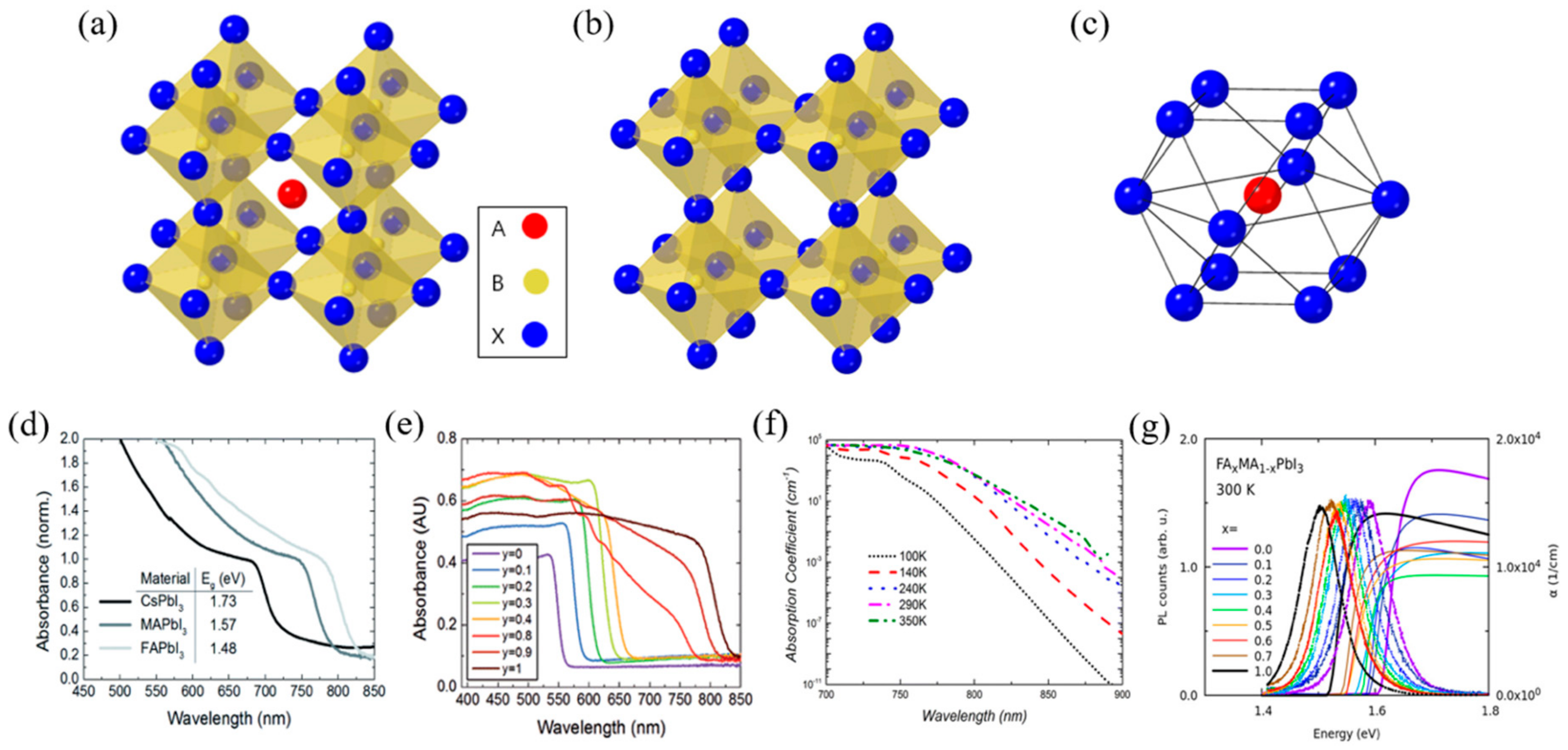
Figure 1. Intrinsic crystal structure and optical properties of perovskite materials. (a) A typical perovskite crystal structure. (b) Crystal structure of B cation and X anion (B cation is located at the octahedral site of X anion). (c) Crystal structure of A cation and X anion (A cation is located at the octahedron site of X anion. (d) UV-vis spectra for the APbI3 perovskites formed, where A is either cesium (Cs), methylammonium (MA) or formamidinium (FA). (e) UV-vis absorption spectra FAPbIyBr3-y perovskites. (f) Temperature dependence of the absorption coefficient of methylammonium lead iodide (MAPbI3) extracted from photoluminescence (PL) spectra. (g) Near-bandgap absorption and photoluminescence spectra at room temperature mixed-organic perovskites [39,40,43,44].
Materials 13 00210 g001
Figure 2. Photoelectrochemical processes involved in (a) water reduction and (b) water oxidation. (c) Proposed mechanistic pathways for H2 generation at a metal center of Mn+. (d) Two mechanistic pathways to form an O–O bond for the molecular catalysts. (ref. [61]).
Materials 13 00210 g002
Figure 3. The operating mechanism of perovskite-based photoelectrochemical device (a) n–i–p configuration, (b) p–i–n configuration.
Materials 13 00210 g003
Figure 4. Examples of the n–i–p configuration of perovskite-based PEC cells. (a) Schematic illustration of the photoelectrochemical test of a Ni-coated perovskite photoanode in a PEC cell using a standard three-electrode system and energy diagram of each material. (b) Photocurrent densities of the compact TiO2 layer (black curve) and CH3NH3PbI3 photoanodes without (blue curve) and with Ni surface layer (red curve). Comparison of photocurrent densities of CH3NH3PbI3 photoanodes (with and without Ni surface layer). (c) Schematic illustration of the integrated photoelectrolysis cell with perovskite photoelectrode. (d) Voltammogram of perovskite photoanode with 10 μm Ni catalyst under simulated illumination (0.7 sun; red curve), under dark (dashed curve), and on metallic Ni electrode (blue curve) as reference. Electrolyte was K-borate solution (pH 9.2) and 1.0 M KOH solution (pH 14) respectively [79,80].
Materials 13 00210 g004
Figure 5. Examples of the n–i–p configuration of perovskite-based PEC cells. (a) Schematic illustration of the perovskite photoanode for PEC water splitting in a standard three-electrode system. (b) Voltammogram of perovskite photoanodes with SC paint layer (red curve) and without SC paint layer (black curve) under simulated illumination and in the dark (green curve), with the CC paste electrode (blue curve) as a reference. (c) Schematic illustration of perovskite photoanode device used CsPbBr3, TiO2 (electron collecting), m-carbon (hole collecting). (d) Linear sweep voltammetry (LSV) of a TiO2|CsPbBr3|m-c|GS and a TiO2|CsPbBr3|m-c|GS|WOC measured at a scan rate of 20 mV s−1, in a 0.1 M KNO3 electrolyte solution with pH 2.5 (pH adjusted with H2SO4) [81,82].
Materials 13 00210 g005
Figure 6. Examples of the p–i–n configuration of perovskite-based PEC cells. (a) Material and electronic configuration of the perovskite-based photocathode. (b) Linear sweep voltammetry of the perovskite-based photocathode at a scan rate of 5 mV s−1. (c) Schematic illustration of the sandwich-like CH3NH3PbI3 photocathode for PEC H2 evolution in a standard three-electrode system. (d) Current density–potential curves for the Pt–Ti/CH3NH3PbI3 photocathode [83,84].
Materials 13 00210 g006
Figure 7. Examples of the p–i–n configuration of perovskite-based PEC cells. (a) Schematic representation of a CsPbBr3-based photocathode. (b) Performance of all-inorganic LHP photocathode under AM 1.5 G simulated sunlight conditions. Current density–potential curves. (c) Cross-sectional schematic of a photocathode stabilized against corrosion in 0.5 M H2SO4(aq) via a hybrid ETL comprising PC61BM with TiO2 deposited by ALD. Photogenerated electrons are conducted through the TiO2 to the Pt catalysts, where electrons are used to reduce protons to hydrogen. (d) Photoelectrochemical behavior of the photocathode in the dark and under continuous and chopped illumination reveals the time scale (ms) and magnitude (>10 mA/cm2) of the photocurrent response [85,86].
Materials 13 00210 g007
Figure 8. Degradation pathway of metal-organic halide perovskite materials in water.
Materials 13 00210 g008
Figure 9. DFT calculation of perovskite’s degradation pathway in water. (a) Formation enthalpies of vacancy point and pair defects as a function of the Fermi energy (EF) under I-poor (Pb-, MA-rich) conditions (left) and I-rich (Pb-, MA-poor) conditions (right). (b) Band alignment and thermodynamic transition levels in MAPbI3, water-intercalated MAPbI3_H2O, and monohydrate MAPbI3·H2O, where deep-lying Pb 5d levels are used as a reference for the VBM and CBM of each phase [92].
Materials 13 00210 g009
Figure 10. Cases of improving stability by passivation. (a) Chronoamperometric trace recorded at an applied potential of 0 V vs. RHE. An aqueous buffer solution (0.1 M borate, pH 8.5), chopped solar light irradiation (AM 1.5 G, 100 mW/cm2, λ > 400 nm). (b) Stability analysis at 0 VRHE. (c) Current vs. time graph of perovskite photoanode under illumination (0.7 sun) and bias (1.3 V vs. RHE) in KOH solution (pH 14). (d) Faradaic efficiency for hydrogen evolution on the Pt–Ti/CH3NH3PbI3 photocathode with Pt and SCE as the counter and reference electrodes, respectively, in 0.5 M H2SO4 solution [80,83,84,85].
Materials 13 00210 g010
Figure 11. Cases of improving stability by passivation. (a) Current versus time graph of a perovskite photoanode at an applied potential of 1.23 V versus RHE under simulated AM 1.5 G solar illumination (100 mW/cm2) in 1 M KOH solution. (b) Photocurrent density versus time of a photocathode with a nominally 15 nm thick Pt catalyst under continuous illumination. The electrode potential was held at 0 V vs. RHE during continuous illumination of 0.5 Sun. (c) Chronoamperometric trace recorded at an applied potential of 1.23 VRHE in KOH electrolyte solution at pH 12.5, under chopped simulated solar light irradiation (AM 1.5 G, 100 mW/cm2) [81,82,86].
Materials 13 00210 g011
Figure 12. Cases of improving stability by using inorganic perovskites. (a) The photocurrent density curve of the Cs2SnI6 compound using a three-electrode system with a 0.3 M NaCl electrolyte and the inserted picture shows the working principle of the system. (b) PEC water splitting performance of a Ba2Bi1.4Nb0.6O6 photoanode. LSV curves of PEC water oxidation in 1 m KOH solution of Ba2Bi1.4Nb0.6O6 film and Co3O4 coated Ba2Bi1.4Nb0.6O6 film (Pt, as counter electrode and cathode). (c) Durability test of the Ba2Bi1.4Nb0.6O6 film at 1.23 V (vs. RHE) [98,99].
Materials 13 00210 g012
Table 1. Photoelectrochemical and photovoltaic performance of perovskite-based cells depending on charge transporting materials, perovskite materials, and cell configurations. (* Approximate value).
Device ConfigurationPassivation MethodJscVocFFPCEOver PotentialOnset PotentialStabilityPhotocurrentFaradaic EfficiencyRef
n–i–p typeFTO/TiO2/MAPbI3/Spiro-OMeTAD/Au/NiNi sputtering19 mA/cm20.95 V0.5910%−0.45 VAg/AgCl *N/A100 s—50%10 mA/cm2 (at 0 VAg/AgCl)N/A[79]
FTO/TiO2/MAPbI3/Spiro-OMeTAD/Au/Field’s metal/NiField’s metal encapsulation21 mA/cm20.98 V0.7815.60%−0.489 VRHE0.75 VRHE *5.5 h—50%14 mA/cm2.(at 1.23 VRHE)N/A[80]
FTO/TiO2/(5-AVA)x(MA)1−xPbI3/CC/SC/CCCC/SC paste doctor bladeN/AN/AN/AN/A0.03 VRHE *0.8 VRHE *12 h—70%12.4 mA/cm2 (at 1.23 VRHE)82%[81]
FTO/TiO2/CsPbBr3/m-carbon/GS/WOCm-carbon/GS doctor blade5.05 mA/cm21.4 V0.7495.30%N/A0.6 VRHE *30 h—50%2.5 mA/cm2 (at 1.23 VRHE)N/A[82]
FTO/TiO2/MAPbI3/spiro-OMeTAD/Ni-Au/CNT-polymer compositeCNT-polymer composite18.3 mA/cm21.06 V0.7414.4%0.85 VRHE *0.3 VRHE *10 h *9.2 mA/cm2 (at 1.23 VRHE)N/A[87]
p–i–n typeFTO/PEDOT:PSS/MAPbI3/PCBM/Ag/Field’s metal/PtField’s metal encapsulation15 mA/cm21 V0.548%−0.2 VRHE *0.7 VRHE *1.8 h—50%−9.8 mA/cm2 (at 0 VRHE)95.10%[31]
ITO/NiO/MAPbI3/PCBM/Ag/Silver paint/Ti foil/PtTi foil deposition20.38 mA/cm21.09 V0.72916.10%0.69 VRHE *0.95 VRHE12 h−18 mA/cm2 (at 0 VRHE)100%*[84]
FTO/NiO/CsPbBr3/ZnO/Ag/Field’s metal/PtField’s metal encapsulation2.5 mA/cm21.37 V0.5581.91%N/A1.16 VRHE1 h—94%−1.2 mA/cm2 (at 0 VRHE)90%[85]
ITO/PEDOT:PSS/Cs0.05(MA0.18FA0.83) 0.95Pb(I0.83Br0.17)3/PCBM/TiO2/PtTiO2 Atomic Layer Deposition21.4 mA/cm20.73 V0.6559.63%−0.05 VRHE0.68 VRHE2 h—75%−10.5 mA/cm2 (at 0 VRHE)N/A[86]
ITO/NiOx/CsFAMAPbI3/PCBM/AZO/FM/PtField’s metal encapsulation23.15 mA/cm20.97 V0.81418.20%0.3 VRHE *0.7 VRHE *18 h *−14.3 mA/cm2 (at 0 VRHE)85% *[88]