Seismic Behavior of Superelastic Shape Memory Alloy Spring in Base Isolation System of Multi-Story Steel Frame


Abstract
1. Introduction
2. SMA Spring Damper
2.1. Manufacturing Process
2.2. Test Results
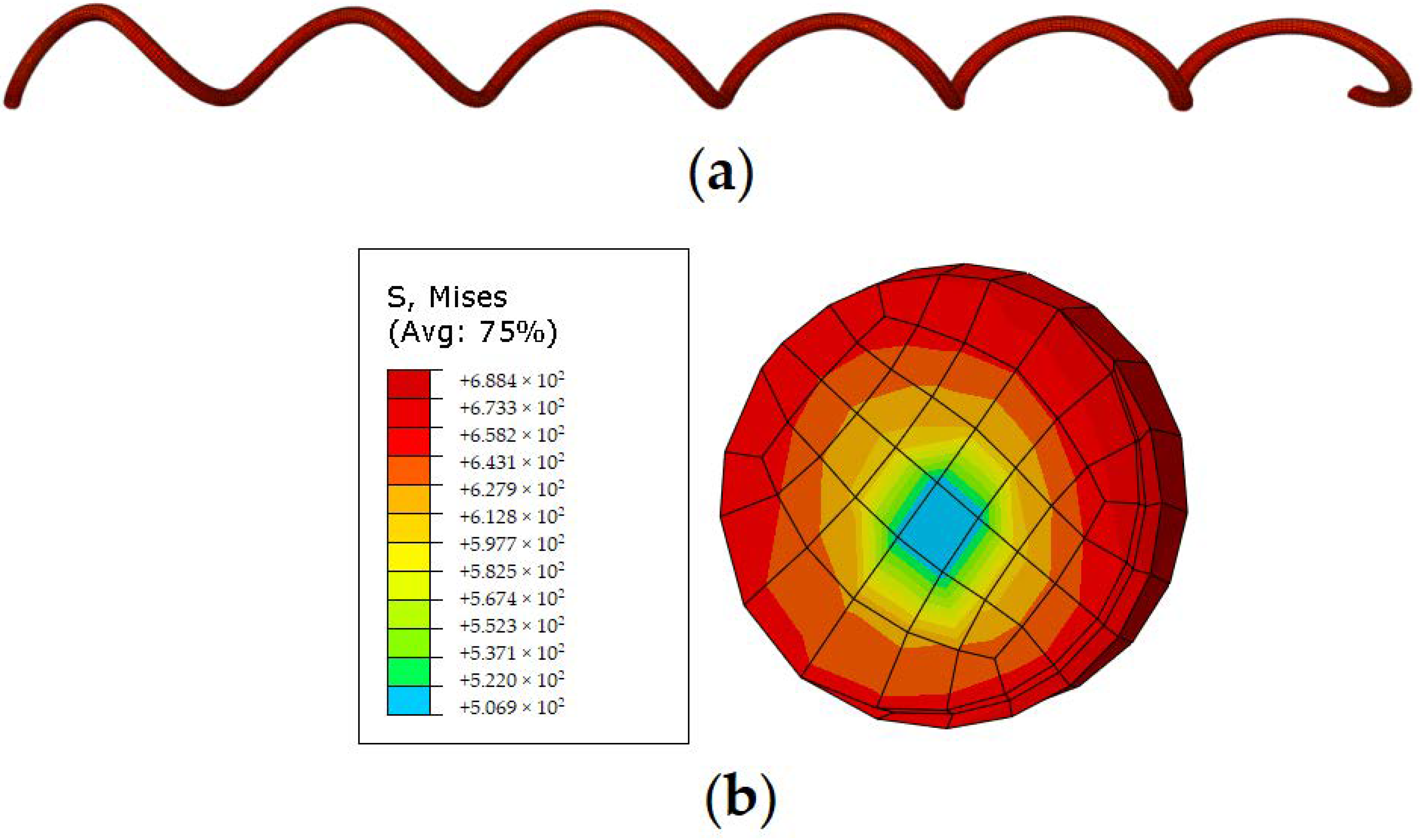
3. Finite Element Simulation in ABAQUS
3.1. Model Calibration
3.2. Material Properties
3.3. Simulation Results
3.4. Parametric Analysis
4. Seismic Analyses
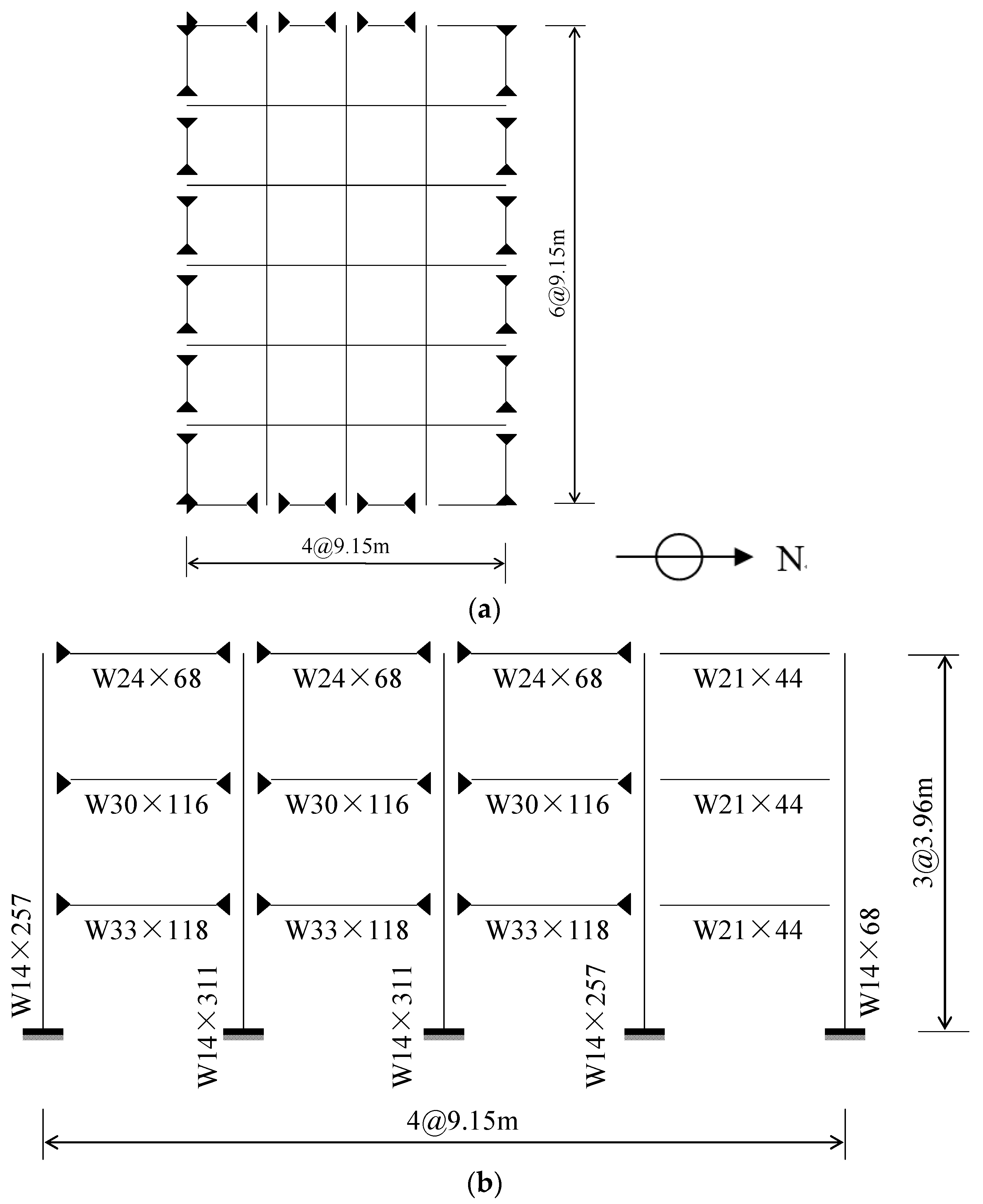
4.1. Building Information
4.2. Design of the Springs
4.3. Numerical Model
4.4. Earthquake Ground Motion Records
4.5. Behavior of the Springs
4.6. Roof Responses
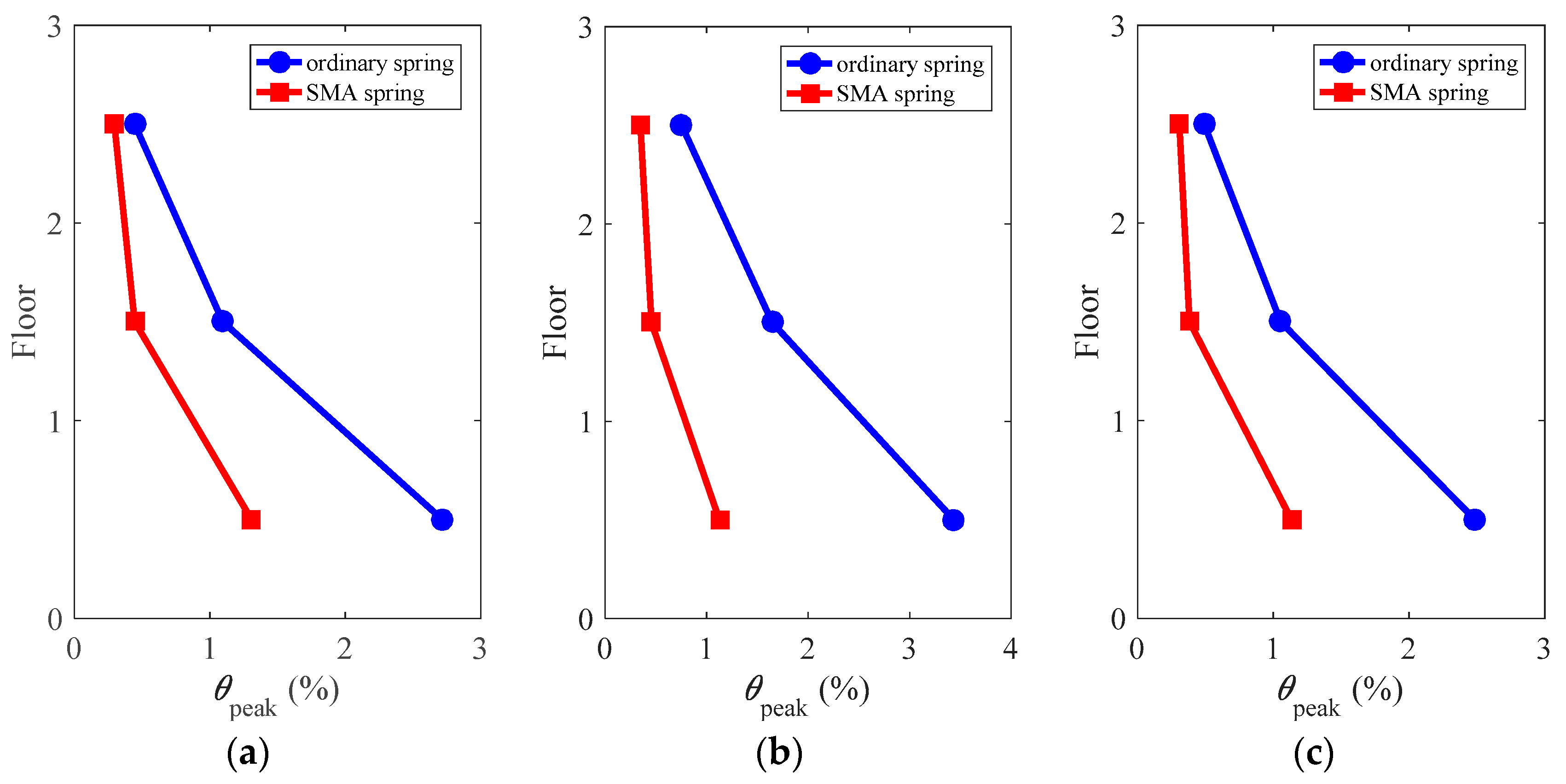
4.7. Peak Interstory Drift Ratio
4.8. Peak Floor Acceleration
4.9. Residual Interstory Drift Ratio
5. Conclusions
- Superelastic SMA spring shows excellent self-centering capability; the equivalent damping ratio can be over 2%;
- Good agreement can be found between the finite element model and test results;
- The SMA spring has versatile cyclic properties, according to the parametric analyses on the geometrical dimensions;
- Based on the comparisons with ordinary elastic spring, the advantages of using SMA spring in the isolation system mainly include the well control of the peak and residual deformations for the superstructure.
Author Contributions
Funding
Acknowledgments
Conflicts of Interest
References
- Buckle, I.G.; Mayes, R.L. Seismic isolation: History, application and performance—A world view. Earthq. Spectra 1990, 6, 161–201. [Google Scholar] [CrossRef]
- Kelly, J.M. The role of damping in seismic isolation. Earthq. Eng. Struct. Dyn. 1999, 28, 3–20. [Google Scholar] [CrossRef]
- Nagarajaiah, S.; Sun, X. Base-isolated FCC building: Impact response in Northridge earthquake. J. Struct. Eng. 2001, 127, 1063–1075. [Google Scholar] [CrossRef]
- Markis, N.; Zhang, J. Seismic response analysis of a highway overcrossing equipped with elastomeric bearing and fluid dampers. J. Struct. Eng. 2004, 130, 830–845. [Google Scholar]
- Dicleli, M. Supplemental elastic stiffness to reduce isolator displacement for seismic isolated bridges in near-fault zones. Eng. Struct. 2007, 29, 763–775. [Google Scholar] [CrossRef]
- Providakis, C.P. Effect of LRB isolators and supplemental viscous dampers on seismic isolated buildings under near-fault excitations. Eng. Struct. 2008, 30, 1187–1198. [Google Scholar] [CrossRef]
- Wang, Y.P.; Chung, L.L.; Liao, W.H. Seismic response analysis of bridges isolated with friction pendulum bearings. Earthq. Eng. Struct. Dyn. 1998, 27, 1069–1093. [Google Scholar] [CrossRef]
- Robinson, W.H. Lead-rubber hysteretic bearings suitable for protecting structures during earthquakes. Earthq. Eng. Struct. Dyn. 1982, 10, 593–604. [Google Scholar] [CrossRef]
- Fenz, D.M.; Constantinou, M.C. Modeling triple friction pendulum bearings for response-history analysis. Earthq. Spectra 2008, 24, 1011–1028. [Google Scholar] [CrossRef]
- Chakraborty, S.; Roy, K.; Ray-Chaudhuri, S. Design of re-centering spring for flat sliding base isolation system: Theory and a numerical study. Eng. Struct. 2016, 126, 66–77. [Google Scholar] [CrossRef]
- Qiu, C.; Zhu, S. Characterization of cyclic properties of superelastic monocrystalline Cu-Al-Be SMA wires for seismic applications. Constr. Build. Mater. 2014, 72, 219–230. [Google Scholar] [CrossRef]
- Duerig, T.W.; Melton, K.N.; Stockel, D.; Wayman, C.M. Engineering Aspects of Shape Memory Alloys; Butterworth-Heinemann: New York, NY, USA, 1990. [Google Scholar]
- Miyazaki, S.; Fu, Y.Q.; Huang, W.M. Thin Film Shape Memory Alloys: Fundamentals and Device Applications; Cambridge University Press: Cambridge, UK, 2009. [Google Scholar]
- Ponzo, F.C.; Nigro, D.; Dolce, M.; Cardone, D.; Cacosso, A. Comparison of different seismic isolation systems through shaking table tests on a steel structure. In Proceedings of the 3rd World Conference on Structural Control, Como, Italy, 7–12 April 2002. [Google Scholar]
- Gur, S.; Mishra, S.K.; Chakraborty, S. Performance assessment of buildings isolated by shape-memory-alloy rubber bearing: Comparison with elastomeric bearing under near-fault earthquakes. Struct. Control Health Monit. 2014, 21, 449–465. [Google Scholar] [CrossRef]
- Ozbulut, O.E.; Silwal, B. Performance assessment of buildings isolated with S-FBI system under near-fault earthquakes. Smart Struct. Syst. 2016, 17, 709–724. [Google Scholar] [CrossRef]
- Qiu, C.; Tian, L. Feasibility analysis of using SMA-based damping device in seismic isolation system of low-rise frame buildings. Int. J. Struct. Stab. Dyn. 2018, 18, 1850087. [Google Scholar] [CrossRef]
- Huang, B.; Zhang, H.; Wang, H.; Song, G. Passive base isolation with superelastic nitinol SMA helical springs. Smart Mater. Struct. 2014, 23, 065009. [Google Scholar] [CrossRef]
- Attanasi, G.; Auricchio, F.; Fenves, G.L. Feasibility assessment of an innovative isolation bearing system with shape memory alloys. J. Earthq. Eng. 2009, 13, 18–39. [Google Scholar] [CrossRef]
- DesRoches, R.; Smith, B. Shape memory alloys in seismic resistant design and retrofit: A critical review of their potential and limitations. J. Earthq. Eng. 2004, 8, 415–429. [Google Scholar] [CrossRef]
- Dolce, M.; Cardone, D. Mechanical behaviour of shape memory alloys for seismic applications 2. Austenite NiTi wires subjected to tension. Int. J. Mech. Sci. 2001, 43, 2657. [Google Scholar] [CrossRef]
- Morgan, N.B.; Broadley, M. Taking the art out of smart!—Forming processes and durability issues for the application of NiTi shape memory alloys in medical devices. In Proceedings of the Materials and Processes for Medical Devices Coference, Anaheim, CA, USA, 25–27 August 2004; pp. 247–252. [Google Scholar]
- Jee, K.K.; Han, J.H.; Kim, Y.B.; Lee, D.H.; Jang, W.Y. New method for improving properties of SMA coil springs. Eur. Phys. J. Spec. Top. 2008, 158, 261–266. [Google Scholar] [CrossRef]
- Savi, M.A.; Pacheco, P.M.C.; Garcia, M.S.; Aguiar, R.A.; de Souza, L.F.G.; da Hora, R.B. Nonlinear geometric influence on the mechanical behavior of shape memory alloy helical springs. Smart Mater. Struct. 2015, 24, 035012. [Google Scholar] [CrossRef]
- Christopoulos, C.; Filiatrault, A.; Folz, B. Seismic response of self-centering hysteretic SDOF systems. Earthq. Eng. Struct. Dyn. 2002, 31, 1131–1150. [Google Scholar] [CrossRef]
- Liang, C.; Rogers, C.A. Design of shape memory alloy springs with applications in vibration control. J. Intell. Mater. Syst. Struct. 1997, 8, 314–322. [Google Scholar] [CrossRef]
- DesRoches, R.; McCormick, J.; Delemont, M. Cyclic properties of superelastic shape memory alloy wires and bars. J. Struct. Eng. ASCE 2004, 130, 38–46. [Google Scholar] [CrossRef]
- Ozbulut, O.E.; Mir, C.; Moroni, M.O.; Sarrazin, M.; Roschke, P.N. A fuzzy model of superelastic shape memory alloys for vibration control in civil engineering applications. Smart Mater. Struct. 2007, 16, 818. [Google Scholar] [CrossRef]
- Zhang, Y.; Camilleri, J.A.; Zhu, S. Mechanical properties of superelastic Cu-AlBe wires at cold temperatures for the seismic protection of bridges. Smart Mater. Struct. 2008, 17, 1–9. [Google Scholar] [CrossRef]
- Dolce, M.; Cardone, D.; Marnetto, R. Implementation and testing of passive control devices based on shape memory alloys. Earthq. Eng. Struct. Dyn. 2000, 29, 945–968. [Google Scholar] [CrossRef]
- Qiu, C.; Zhu, S. Performance-based seismic design of self-centering steel frames with SMA-based braces. Eng. Struct. 2017, 130, 67–82. [Google Scholar] [CrossRef]
- Ohtori, Y.; Christenson, R.E.; Spencer, B.F., Jr.; Dyke, S.J. Benchmark control problems for seismically excited nonlinear buildings. J. Eng. Mech. 2004, 130, 366–385. [Google Scholar] [CrossRef]
- OpenSees. Open System for Earthquake Engineering Simulation (OpenSees), v 2.4.1 [Computer Software]; Pacific Earthquake Engineering Research Center: Berkeley, CA, USA, 2013. [Google Scholar]
- Somerville, P.G.; Smith, N.F.; Punyamurthula, S. Development of Ground Motion Time Histories for Phase 2 of the FEMA/SAC Steel Project; SAC Joint: Richmond, CA, USA, 1997. [Google Scholar]
- American Society of Civil Engineers (ASCE). Seismic Rehabilitation of Existing Buildings (41-06); ASCE: Reston, VA, USA, 2007. [Google Scholar]
- McCormick, J.; Aburano, H.; Ikenaga, M.; Nakashima, M. Permissible residual deformation levels for building structures considering both safety and human elements. In Proceedings of the 14th World Conference on Earthquake Engineering, Beijing, China, 12–17 October 2008. [Google Scholar]


| EA | EM | σMs | σMf | σAs | σAf | εt |
|---|---|---|---|---|---|---|
| 48 GPa | 38 GPa | 550 MPa | 760 MPa | 520 MPa | 300 MPa | 0.04 |
| Specimen No. | Parameters | |||||
|---|---|---|---|---|---|---|
| D (mm) | d (mm) | C | N | Δ (mm) | L (mm) | |
| S1 | 16 | 2 | 8 | 6 | 8 | 62 |
| S2 | 16 | 3 | ||||
| S3 | 16 | 4 | ||||
| S4 | 18 | 2 | ||||
| S5 | 20 | 2 | ||||
| Stiffness (N/mm) | Specimens | ||||
|---|---|---|---|---|---|
| S1 | S2 | S3 | S4 | S5 | |
| Simulation | 2.01 | 10.69 | 33.85 | 1.41 | 0.99 |
| Theory | 1.97 | 9.97 | 31.52 | 1.38 | 1.01 |
| Error | 1.9% | 6.7% | 6.9% | 2.1% | −1.9% |
| Designation | Web Thickness (in) | Flange Width (in) | Flange Thickness (in) |
|---|---|---|---|
| W24 × 68 | 0.415 | 8.965 | 0.585 |
| W21 × 44 | 0.350 | 6.500 | 0.450 |
| W30 × 116 | 0.565 | 10.495 | 0.850 |
| W33 × 118 | 0.550 | 11.480 | 0.740 |
| W14 × 257 | 1.175 | 15.995 | 1.890 |
| W14 × 311 | 1.410 | 16.230 | 2.260 |
| Spring Type | Length | Cross-Sectional Area | Elastic Modulus | “Yield” Stress | Post-Yield Stiffness Ratio | Hysteresis Width |
|---|---|---|---|---|---|---|
| SMA spring | 0.4 m | 344 mm2 | 50 Gpa | 500 N/m2 | 0.26 | 0.5 |
| Ordinary spring | 0.4 m | 344 mm2 | - | - | - | - |
| SAC Name | Record | Earthquake Magnitude | Distance (km) | Duration (s) | PGA (cm/s2) |
|---|---|---|---|---|---|
| LA01 | Imperial Valley, 1940, El Centro | 6.9 | 10 | 39.38 | 452.03 |
| LA13 | Northridge, 1994, Newhall | 6.7 | 6.7 | 59.98 | 664.93 |
| LA17 | Northridge, 1994, Sylmar | 6.7 | 6.4 | 59.98 | 558.43 |
© 2019 by the authors. Licensee MDPI, Basel, Switzerland. This article is an open access article distributed under the terms and conditions of the Creative Commons Attribution (CC BY) license (http://creativecommons.org/licenses/by/4.0/).
Share and Cite
Liu, Y.; Wang, H.; Qiu, C.; Zhao, X. Seismic Behavior of Superelastic Shape Memory Alloy Spring in Base Isolation System of Multi-Story Steel Frame. Materials 2019, 12, 997. https://doi.org/10.3390/ma12060997
Liu Y, Wang H, Qiu C, Zhao X. Seismic Behavior of Superelastic Shape Memory Alloy Spring in Base Isolation System of Multi-Story Steel Frame. Materials. 2019; 12(6):997. https://doi.org/10.3390/ma12060997
Chicago/Turabian StyleLiu, Yuping, Hongyang Wang, Canxing Qiu, and Xingnan Zhao. 2019. "Seismic Behavior of Superelastic Shape Memory Alloy Spring in Base Isolation System of Multi-Story Steel Frame" Materials 12, no. 6: 997. https://doi.org/10.3390/ma12060997
APA StyleLiu, Y., Wang, H., Qiu, C., & Zhao, X. (2019). Seismic Behavior of Superelastic Shape Memory Alloy Spring in Base Isolation System of Multi-Story Steel Frame. Materials, 12(6), 997. https://doi.org/10.3390/ma12060997