1. Introduction
Three-dimensional graphene foams (3D-GrFs) [
1,
2,
3], unlike conventional polymeric open-cell foam materials, are a very new kind of nanofoam materials with three-dimensionally interconnected constituent graphene flakes. These 3D-GrFs have been synthesized by some approaches such as hard templating [
4], sol–gel reaction [
5], solution processing [
6], powder metallurgy [
7], 3D printing [
8], freeze drying [
9], hydrothermal reduction [
10], and chemical vapor deposition [
11]. These 3D-GrFs possess excellent properties of good electrical conductivity, high energy dissipation, super low density, superelasticity, and electrochemical stability [
12,
13,
14,
15]. These combined properties enable 3D-GrFs to be applied in electronics and energy storage/conversion systems [
16,
17], gas detection [
15], sorbent materials [
18], stretchable electronics [
11], and so on.
In contrast to many experimental studies on the mechanical property of 3D-GrFs, few computational and theoretical investigations have been conducted to evaluate the relationship between the macro-mechanical characteristics and the intrinsic micro/nanostructures. Jinlong et al. [
19] investigated and discussed the effects of graphene layer number and 3D-GrF defects on the electrical and mechanical properties of 3D-GrFs. Based on the coarse-grained molecular dynamics simulation, the constitutive relation between 3D-GrFs and microscopic deformation mechanisms were investigated by Wang et al. [
20]. The mechanical properties in both tension and compression of 3D-GrFs at macro and nanoscales were evaluated by Nieto et al. [
21]. Qin et al. [
3] stated that 3D-GrFs have an exceptionally high tensile strength and they are 10 times as strong as mild steel. Nautiyal et al. [
22] studied the dynamic mechanical properties of 3D-GrFs by nanoindentation technique.
As material size changes from macroscale to nano/microscale, size effect on mechanical properties of materials should be taken into account. It is reported that size effects in micro/nanostructures have been experimentally observed [
23,
24,
25]. Due to the exclusion of size effect in the classical theory (CT), several non-classical theories were developed for analysis of micro/nanostructures. One of the non-classical theories incorporating size effect is the modified couple stress theory [
26,
27]. This theory has been employed in many aspects to interpret the size effect in micro/nanostructures [
28,
29,
30,
31,
32,
33,
34].
Micro/nanoshells are an important and widely used form of micro/nanostructures in various engineering fields. Gholami et al. [
35] analyzed the dynamic stability and axial buckling of functionally graded cylindrical microshells. Based on the strain gradient elasticity theory, Zhang et al. [
36] developed a shear deformable functionally graded microshell model. Ghayesh and Farokhi [
37] studied the nonlinear dynamical characteristics of doubly curved shallow microshells. SafarPour et al. [
38] investigated the influences of various temperature distributions on the vibration of functionally graded rotating cylindrical microshells. Afterward, the buckling behavior of functionally graded sandwich microshells under axial loads was studied by Zeighampour and Shojaeian [
39]. Wang et al. [
40] studied nonlinear vibrations of cylindrical nanoshells conveying fluid in the framework of the surface stress elasticity theory.
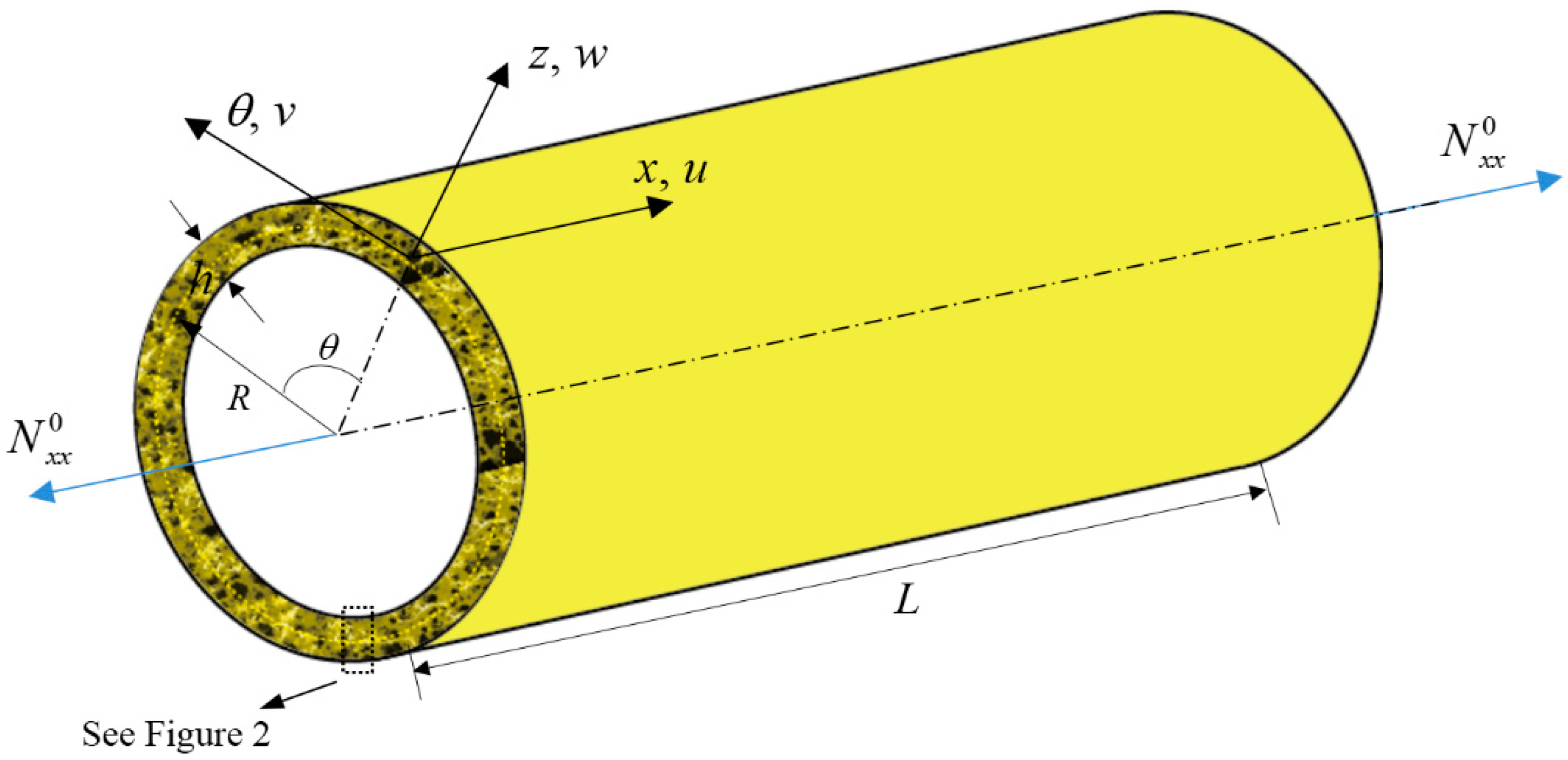
To date, no work has been published on the mechanical properties of 3D-GrF microshells. In this paper, we aim to conduct size-dependent buckling and free vibration analysis of 3D-GrF cylindrical microshells. The couple stress theory and Love’s thin shell theory are used to derive the governing equations. After that, natural frequencies and critical buckling loads are solved by adopting the Navier method and Galerkin method. Finally, the results are illustrated for different parameters.
4. Results and Discussion
In order to verify the correctness of the derivation in this paper, we chose an SS–SS isotropic homogeneous shell to make a comparison without considering the small-scale effect (
l = 0). The system parameters used are as follows:
ρ = 2300 kg/m
3,
ν = 0.3,
E = 1.06 TPa,
R = 2.32 nm,
L/
R = 5. As can be seen in
Table 3, very good agreement was achieved.
Considering the scale effect, dimensionless natural frequencies of an isotropic homogeneous cylindrical nanoshell were calculated, and are compared with the literature in
Table 4. Here the parameters used are the same as those in
Table 3. It was found that the present results match those given by Beni et al. [
42] well, bespeaking the validity of the present study.
To make further comparisons, we considered a homogeneous cylindrical shell with the C–C boundary condition. The comparison result is listed in
Table 5. It can be seen that the present results agree well with those in the literature [
64].
Hereinafter, we conducted free vibration and buckling analyses of 3D-GrF cylindrical microshells. If not specified, the geometrical and material properties of the 3D-GrF microshell are:
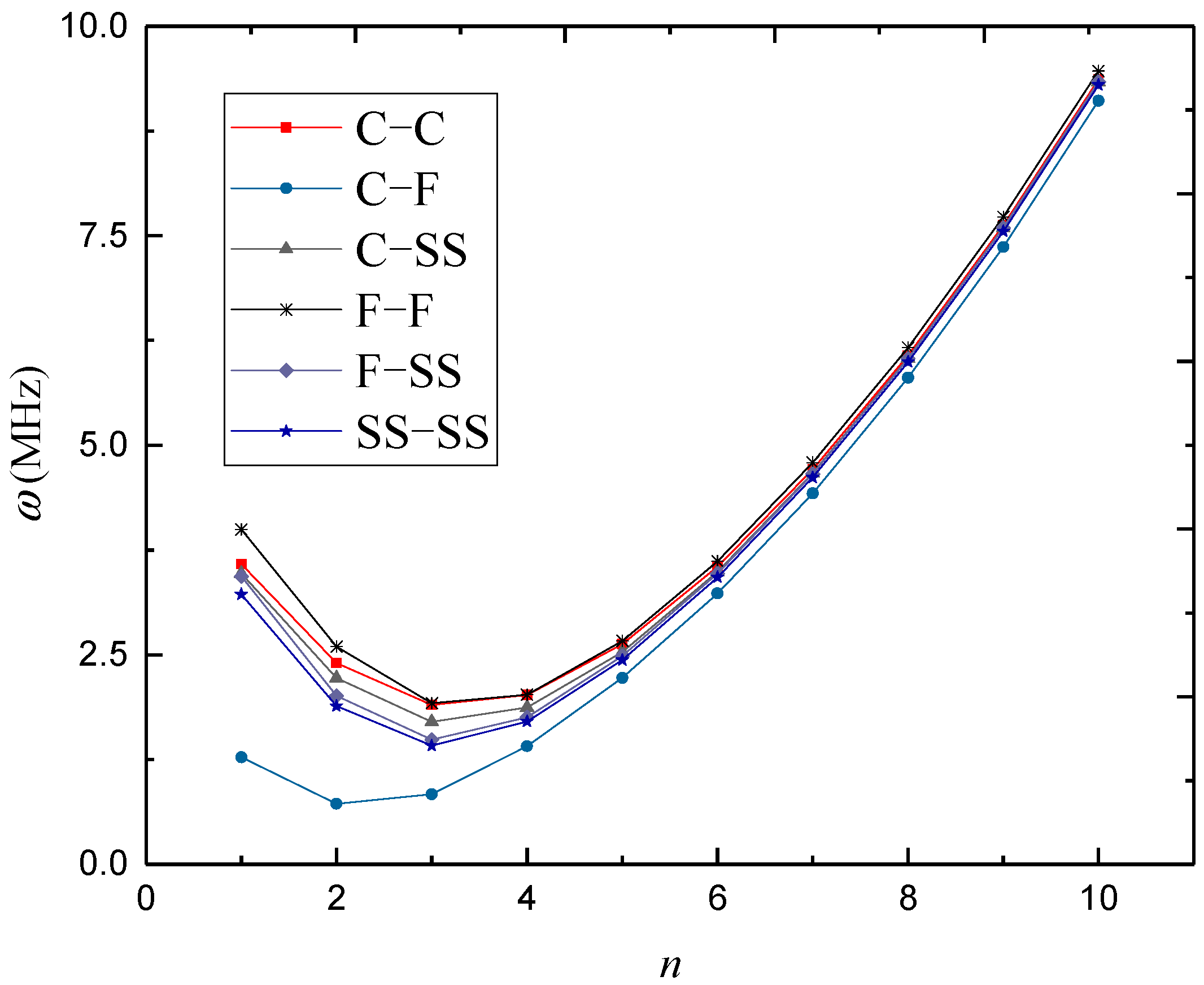
In
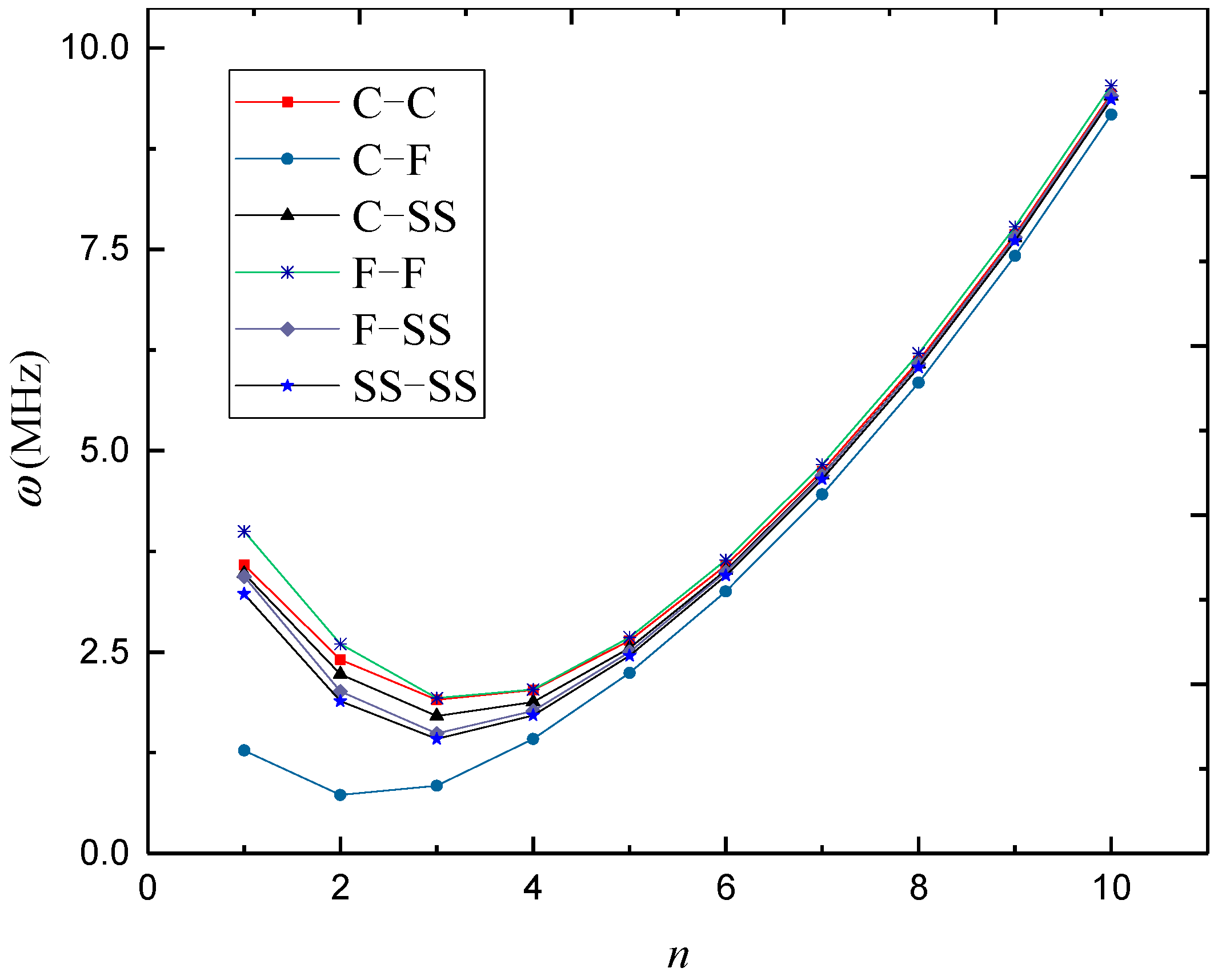
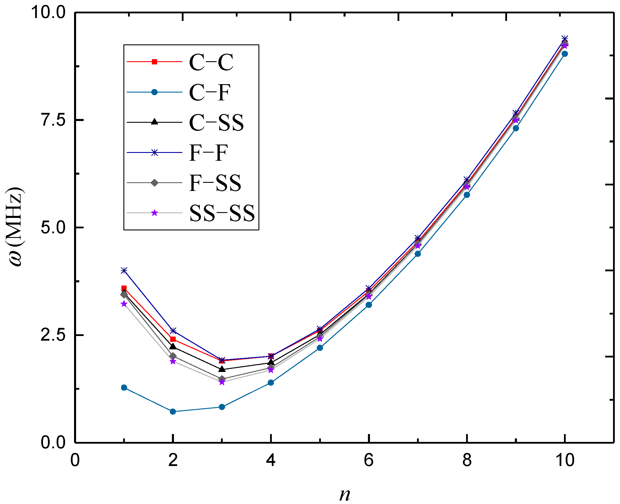
Figure 3,
Figure 4 and
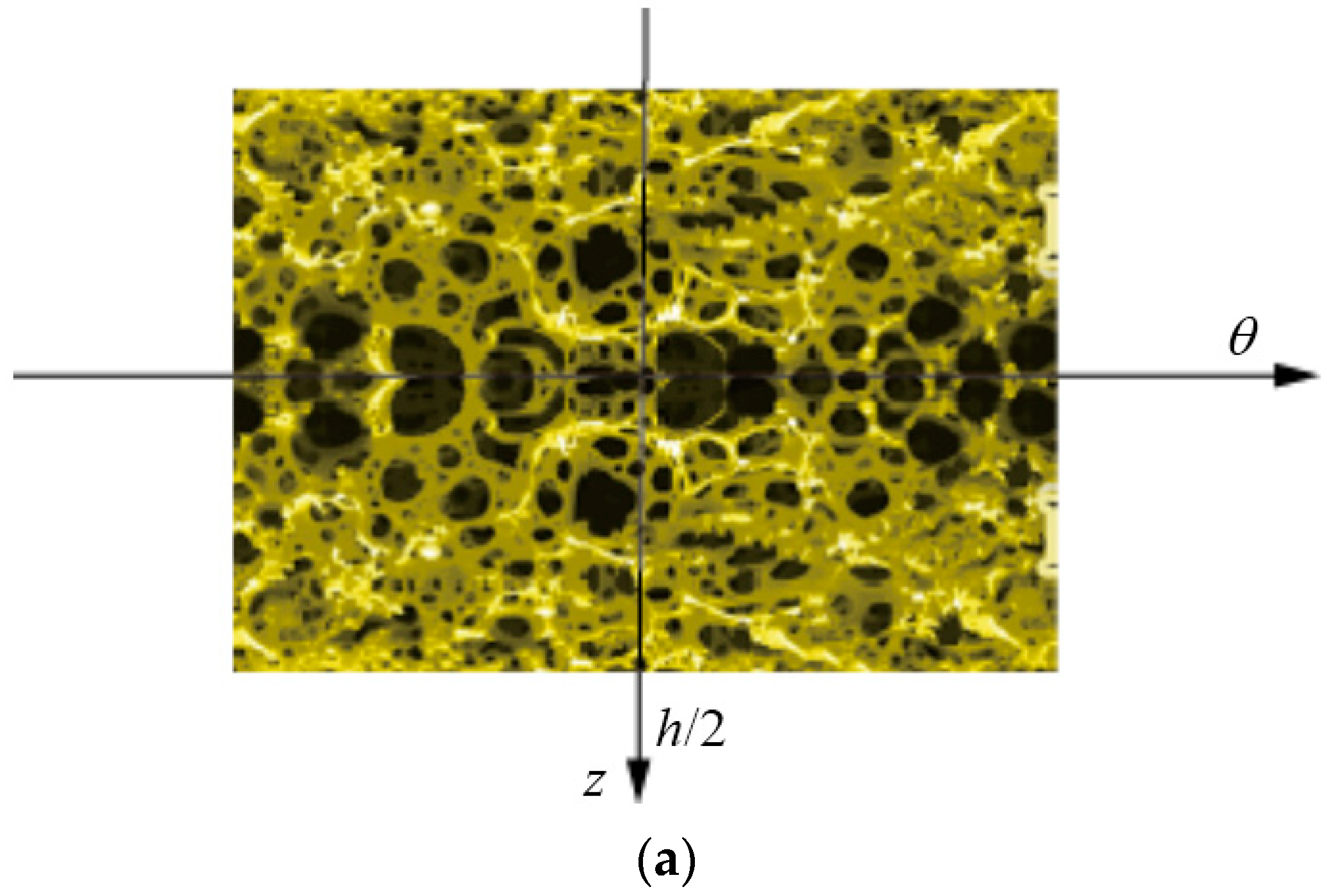
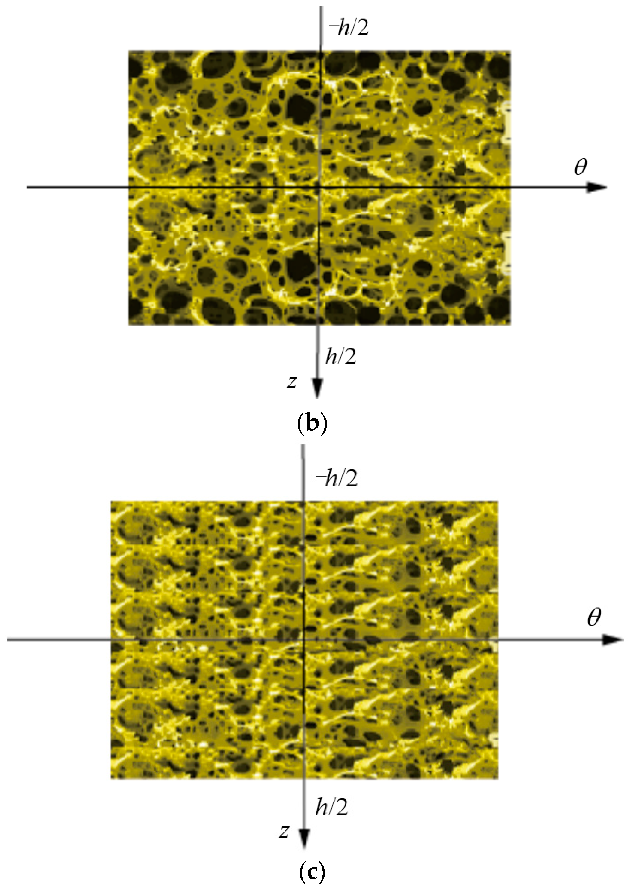
Figure 5, natural frequencies of 3D-GrF microshells under various boundary conditions are shown for different foam distributions, where
κ0 = 0.2. For all six of the boundary conditions, one can see the natural frequencies first decreased and then increased as circumferential number
n increased. The minimum frequency occurred at
n = 2 for the C–F boundary condition and occurred at
n = 3 for the other boundary conditions. In addition, the natural frequency of the C–F microshell was the lowest while that of the F–F one was the highest. When the circumferential wave number was greater than 5, natural frequencies under various boundary conditions tended toward the same value. This result shows that the boundary condition effect was closely associated with the circumferential wave number.
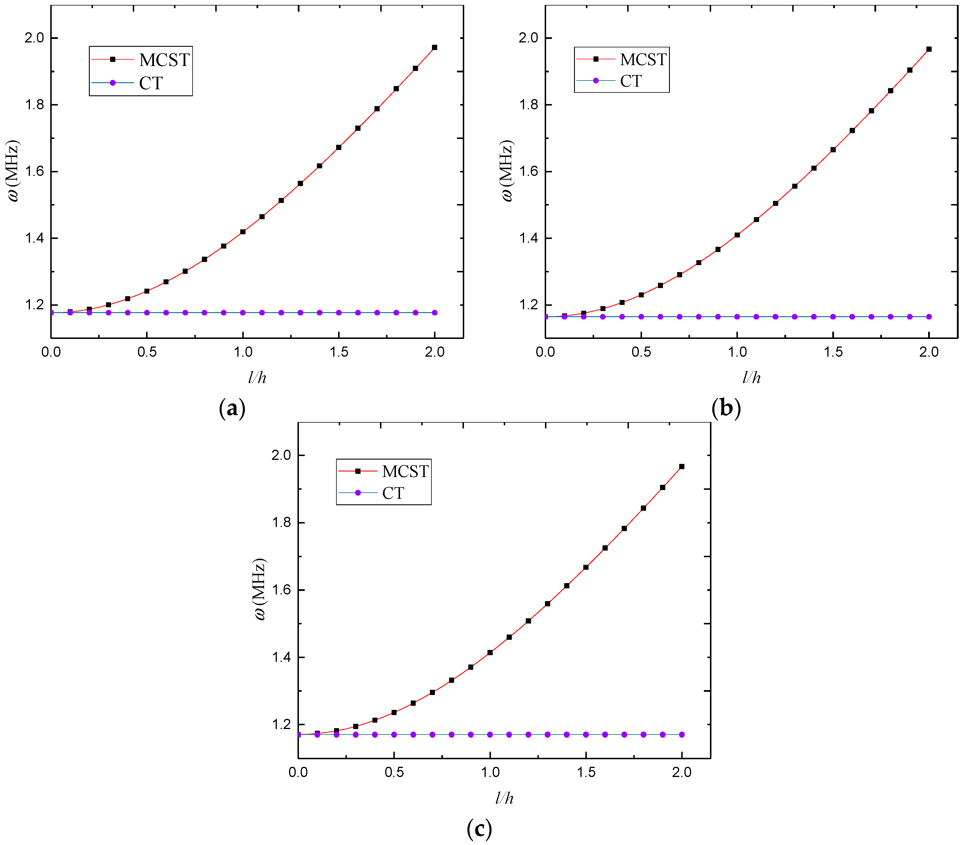
Based on the modified couple stress theory and classical continuum theory,
Figure 6 shows the natural frequency versus dimensionless length scale parameter for the SS–SS 3D-GrF microshell, where
n = 3 and
κ0 = 0.2. One can see that the natural frequency from the modified couple stress theory increased while that from the classical theory did not change with length scale parameter. This is because size effect tends to increase the stiffness of the 3D-GrF microshell. Nevertheless, the classical shell theory fails to incorporate this effect and thus produces inaccurate results.
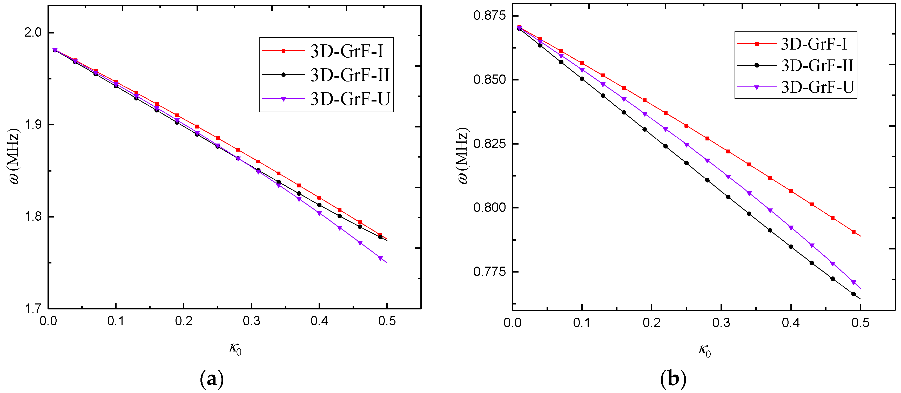
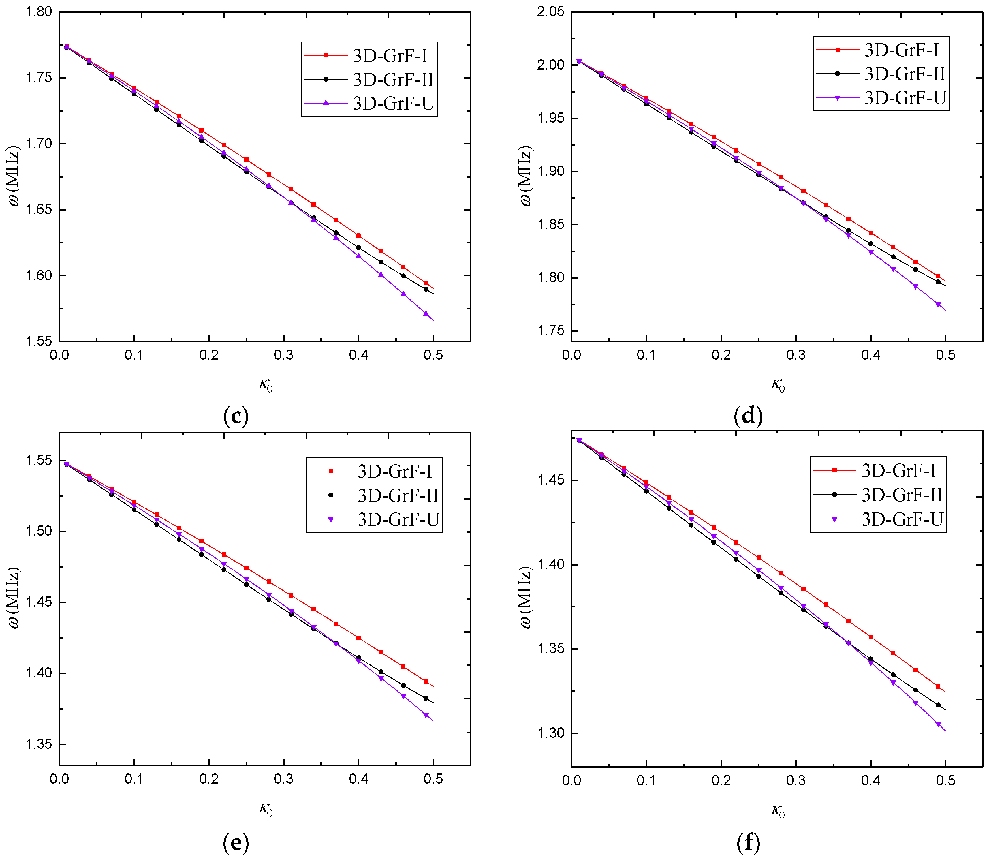
Figure 7 gives the variation of natural frequency against the foam coefficient for different foam distributions. The results show that the increase in the foam coefficient led to a decrease in the natural frequencies of 3D-GrF cylindrical microshells. When the foam coefficient was small, the 3D-GrF-I microshell had the highest natural frequency while the 3D-GrF-II one had the lowest natural frequency. With the increase in the foam coefficient, however, the natural frequency of the 3D-GrF-U microshell dropped faster than that of the 3D-GrF-II one. At last, the 3D-GrF-U microshell had the lowest natural frequency among the three types of foam distribution, except in the C–F boundary condition.
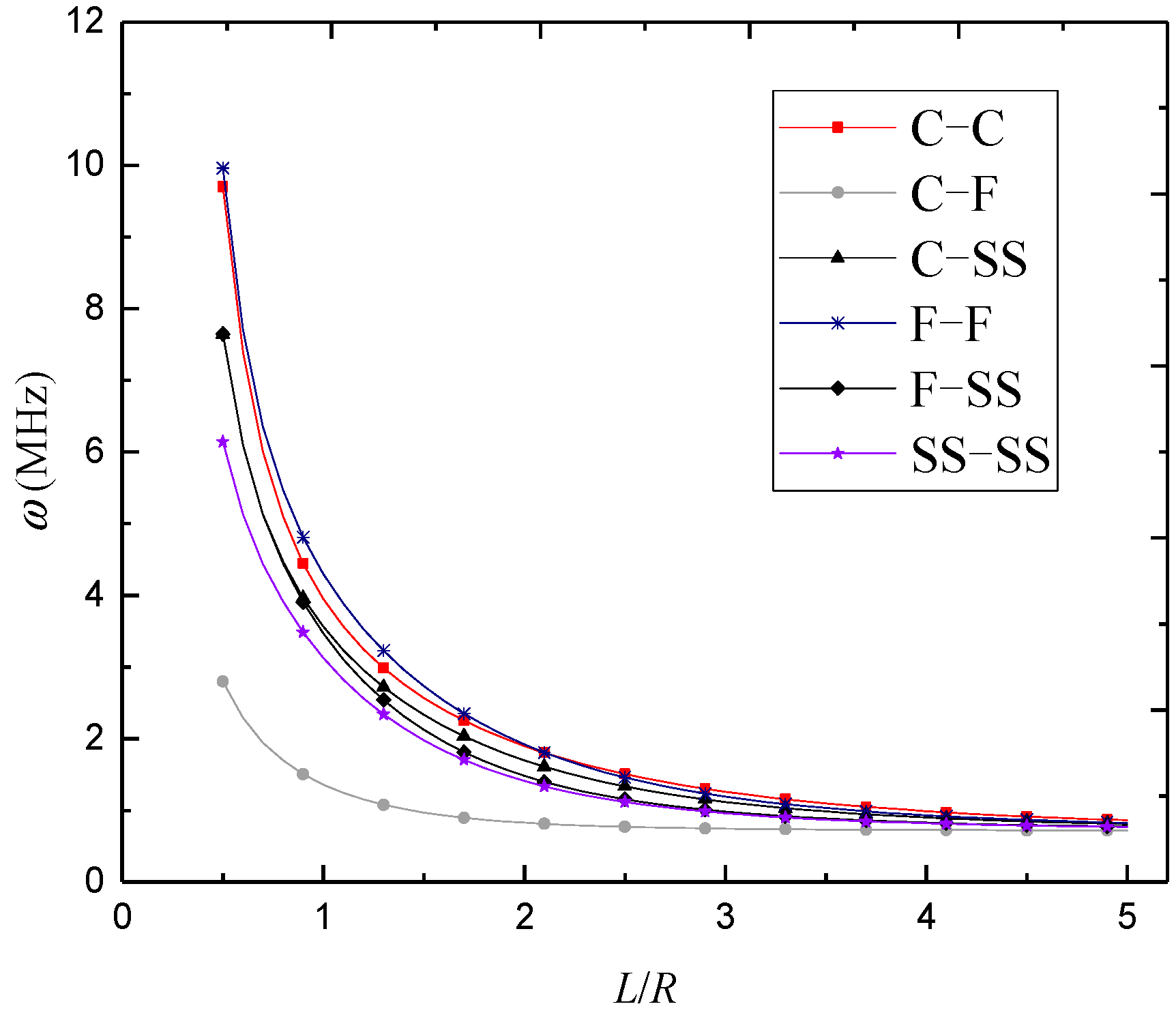
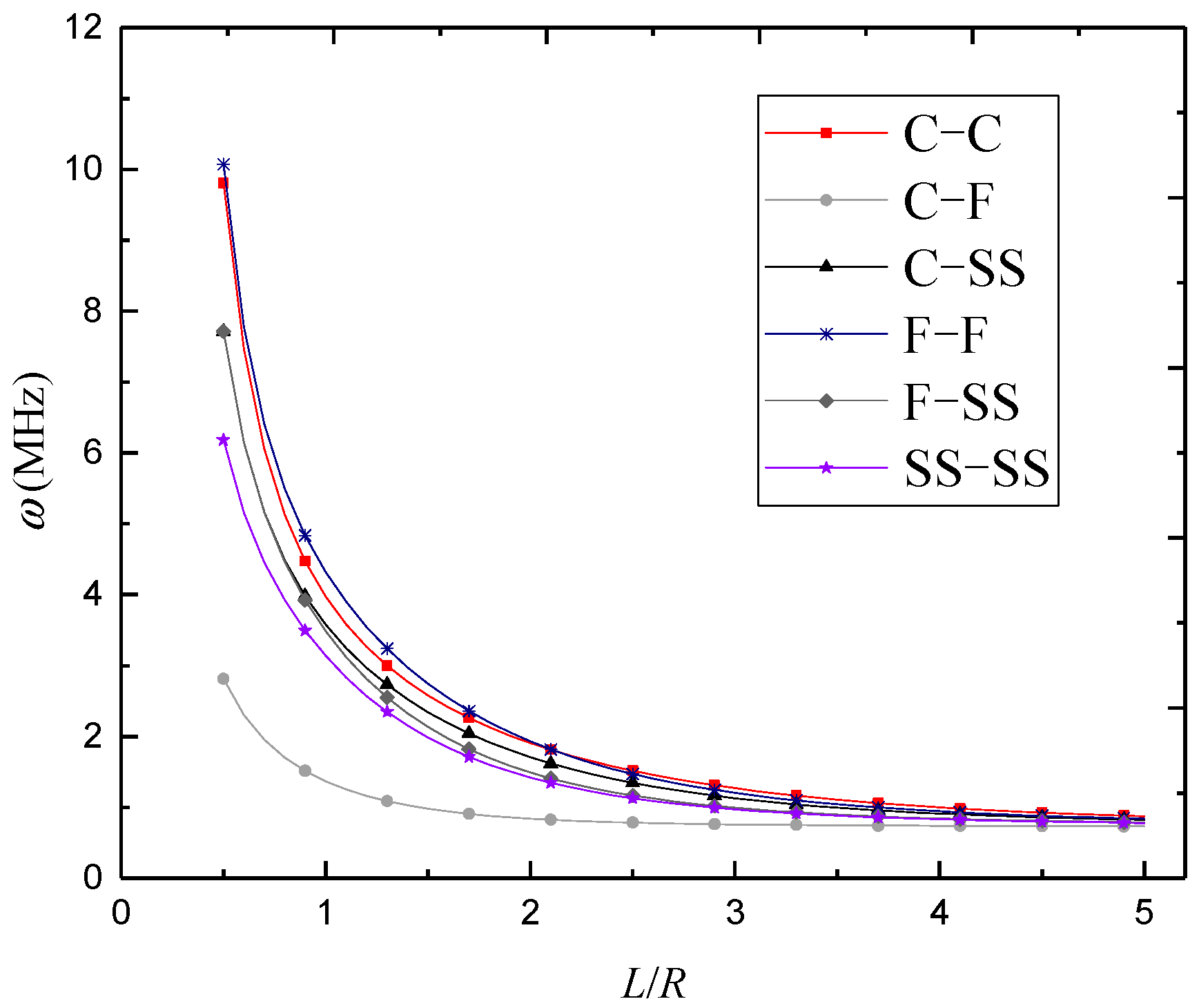
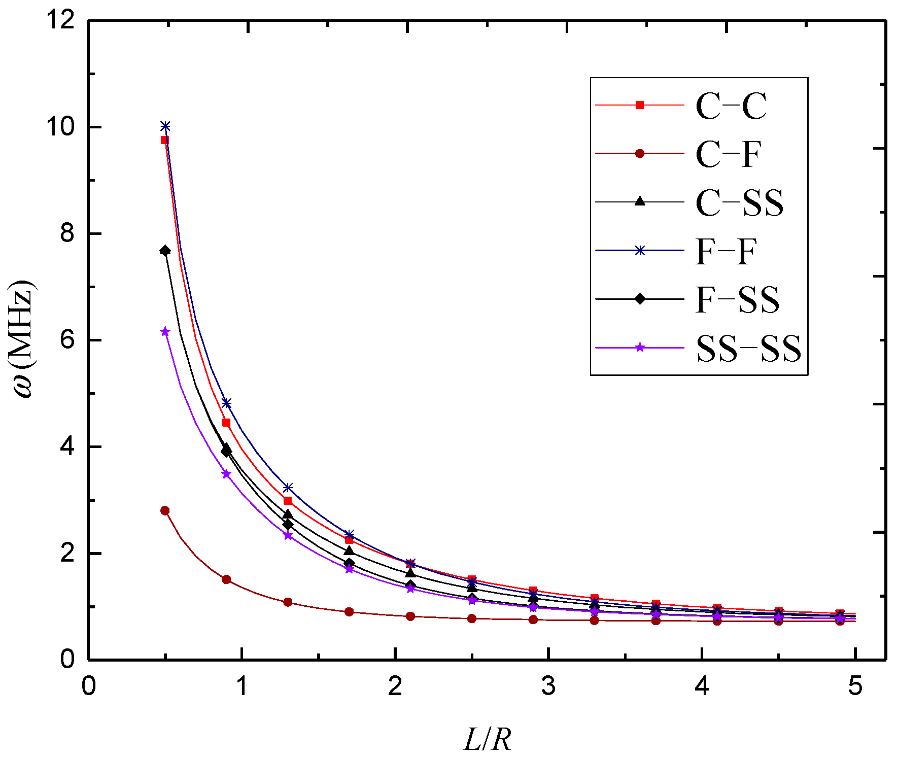
The variations of natural frequency against the length-to-radius ratio for different foam distributions are illustrated in
Figure 8,
Figure 9 and
Figure 10, where
n = 3 and
κ0 = 0.2. It was found that the natural frequencies kept decreasing with the length-to-radius ratio. It can also be seen that the natural frequencies of 3D-GrF microshells under various boundary conditions tended toward the same value as the length-to-radius ratio increased.
Table 6,
Table 7 and
Table 8 show the natural frequency versus radius-to-thickness ratio for different foam distributions, where
n = 3 and
κ0 = 0.2. It is clear that natural frequencies decreased as the radius-to-thickness ratio rose for all the boundary conditions.
Table 9 lists the variation of buckling load against circumferential wave number for the SS–SS 3D-GrF microshell, where
L/
R = 3 and
κ0 = 0.2. Results show the buckling loads initially decreased and then increased with the circumferential wave number. It can be seen that the critical buckling load
Pcr occurred at
n = 3. Therefore, mode (
m = 1,
n = 3) is chosen as a representative mode in the next buckling studies.
The buckling load against radius-to-thickness ratio for the SS–SS 3D-GrF microshell is listed in
Table 10, where different foam distributions are taken into account. It is shown that the larger radius-to-thickness ratio led to the lower buckling load. One can also see that the buckling loads evaluated by the modified couple stress theory were higher than those evaluated by the classical theory, showing that the classical theory underestimated the buckling loads of 3D-GrF microshells.
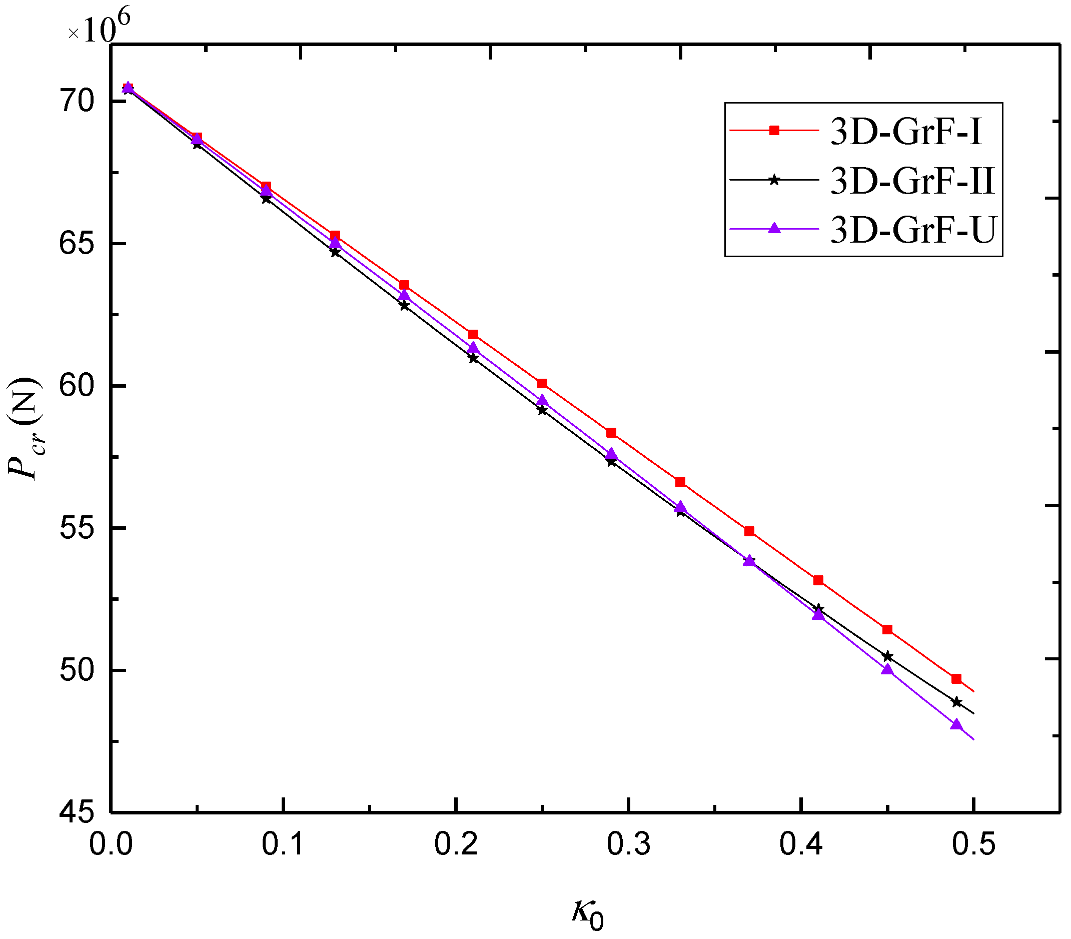
Figure 11 examines the critical buckling load against the foam coefficient for SS–SS 3D-GrF microshells with different foam distributions. One can see that the higher foam coefficient led to the lower critical buckling load. Additionally, the 3D-GrF-I microshell had the highest critical buckling load. This shows that compact inner and outer surfaces and sparse mid-plane can lead to higher structural stiffness of 3D-GrF microshells.
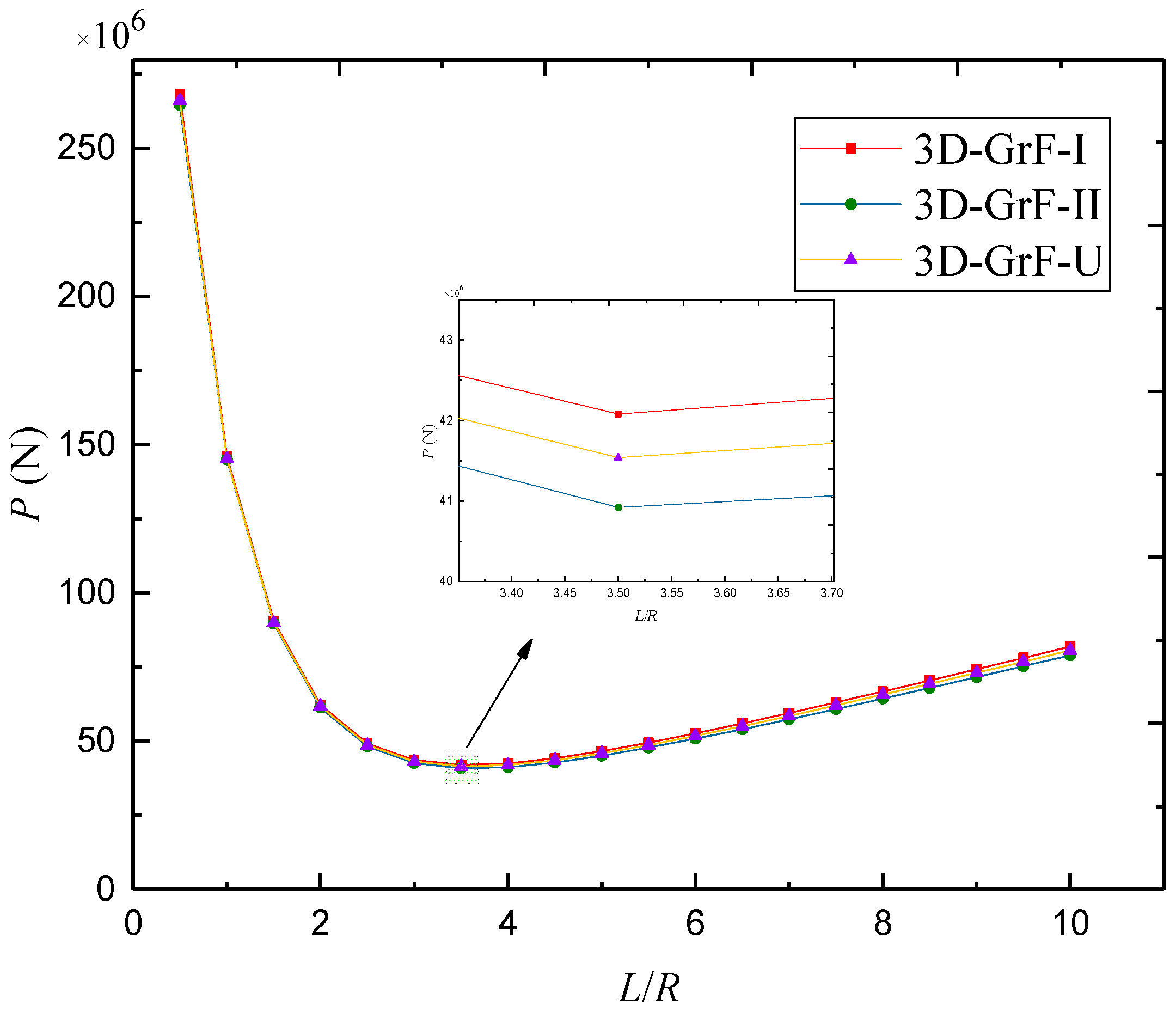
Figure 12 depicts the buckling load against length-to-radius ratio for SS–SS 3D-GrF microshells with different foam distributions. With the increase of length-to-radius ratio, buckling load decreased initially and then increased. The lowest value of buckling loads occurred at nearby
L/
R = 3.5 for all types of foam distribution.


