Response of Connections between Concrete Corbels and Safety Barriers


Abstract
:1. Introduction
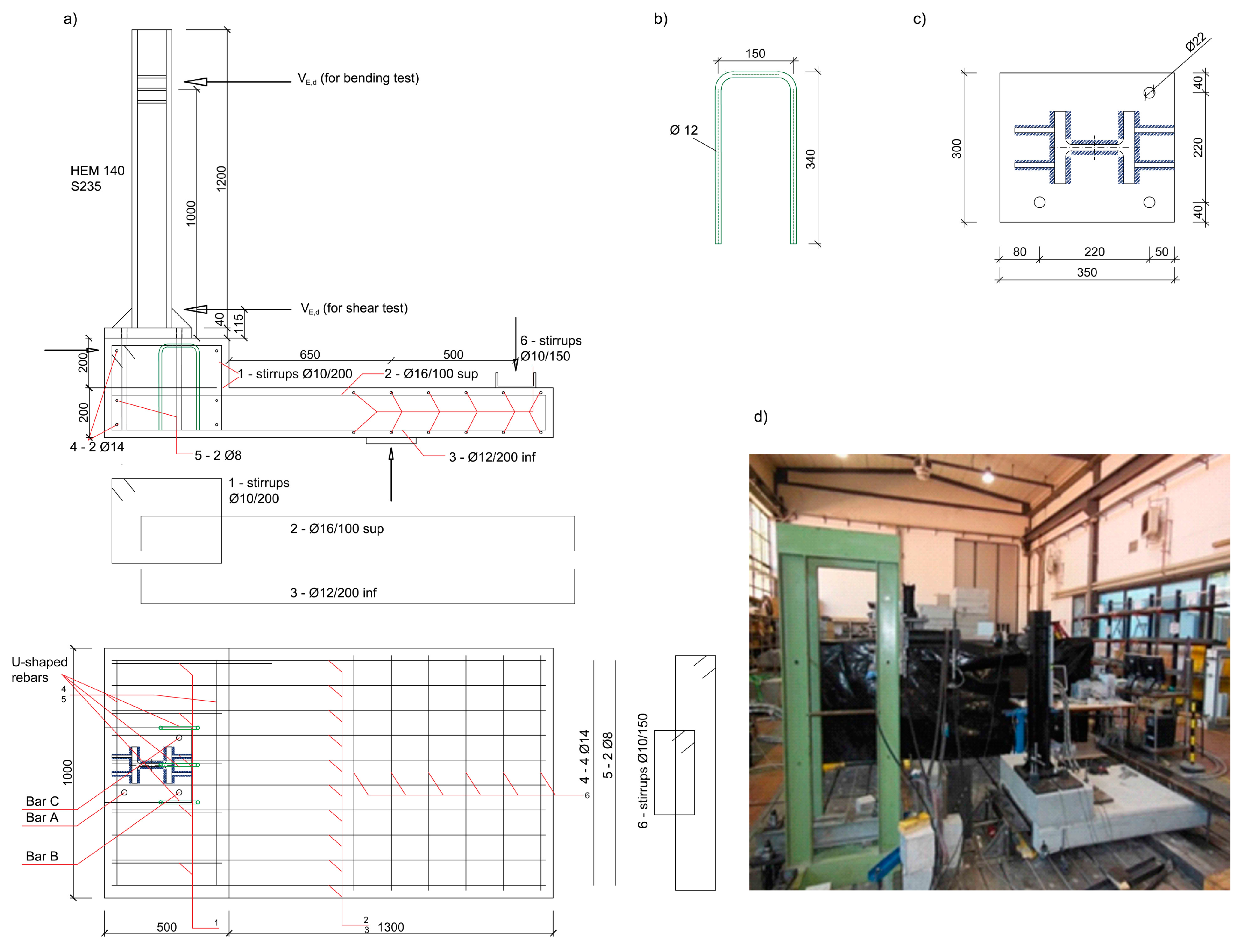
2. Experimental Investigation
2.1. Sample Preparation
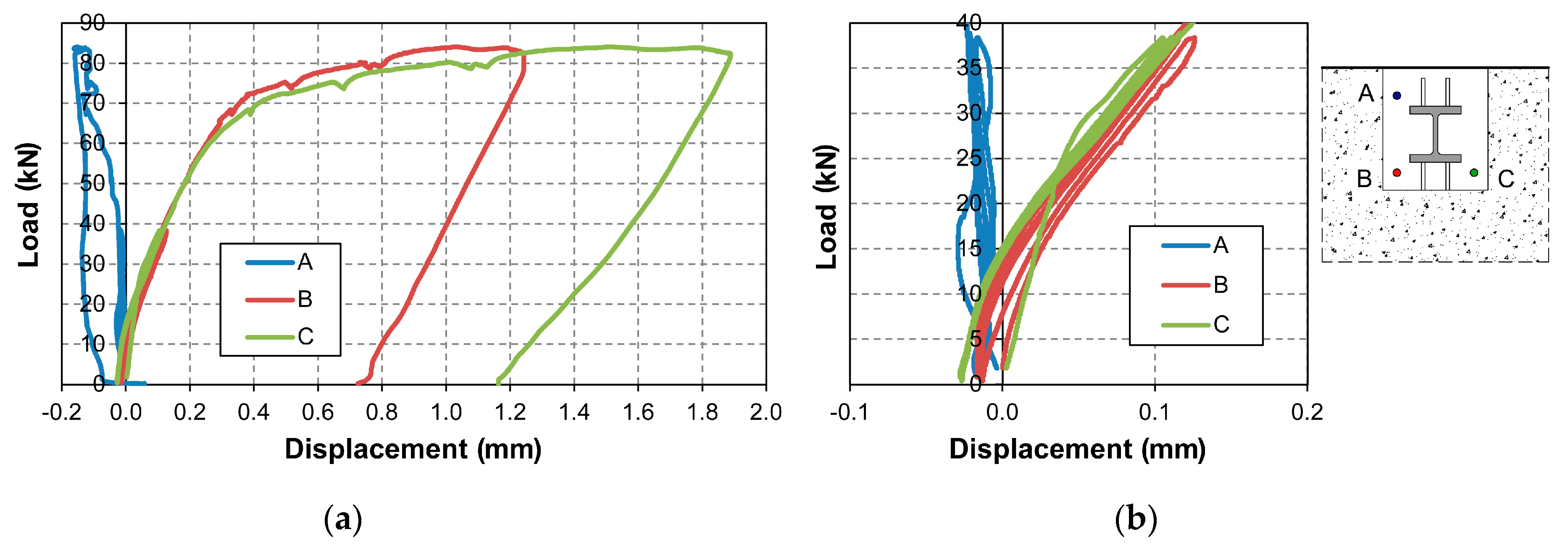
2.2. Test Protocol
- Three loading cycles from 0 kN to 38 kN;
- Loading up to 51 kN and check of crack pattern (load held for 2–3 min);
- Loading up to 65 kN for tests 1 and 2 while up to 84 kN for test 3, to inquire further capacity of the specimen;
- Unloading.
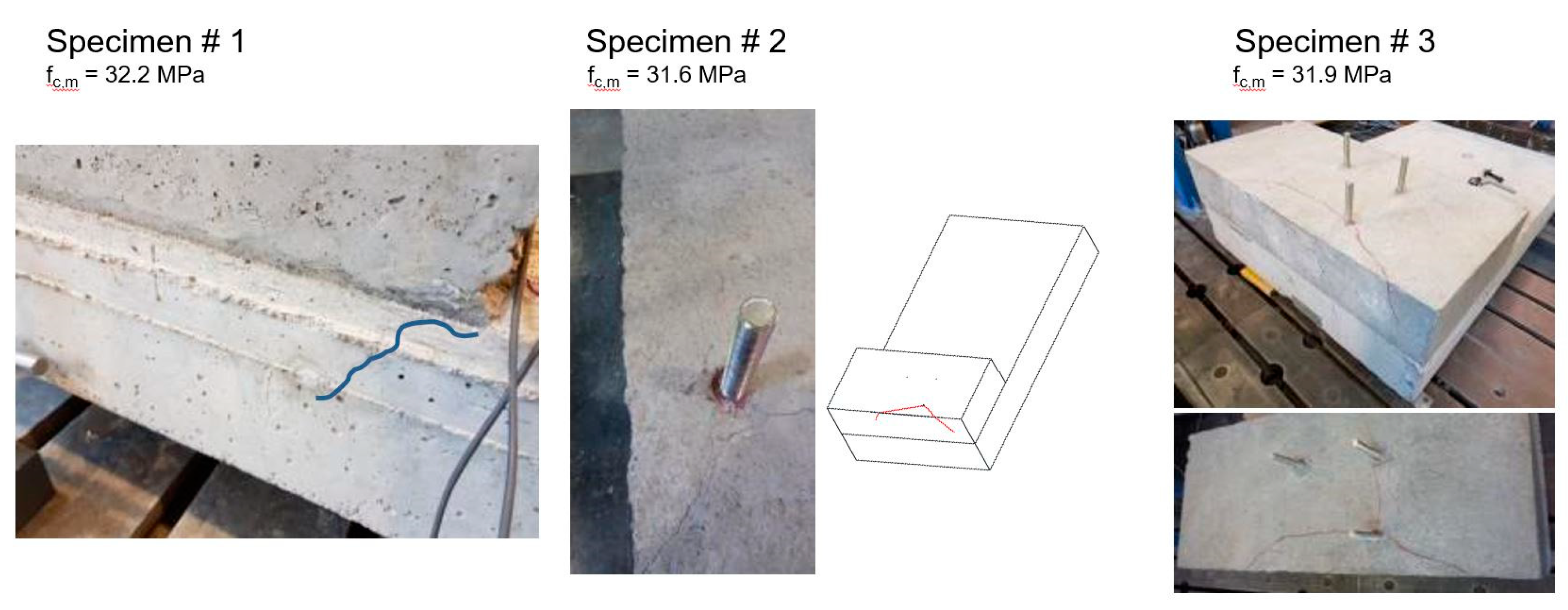
3. Experimental Results
4. Discussion
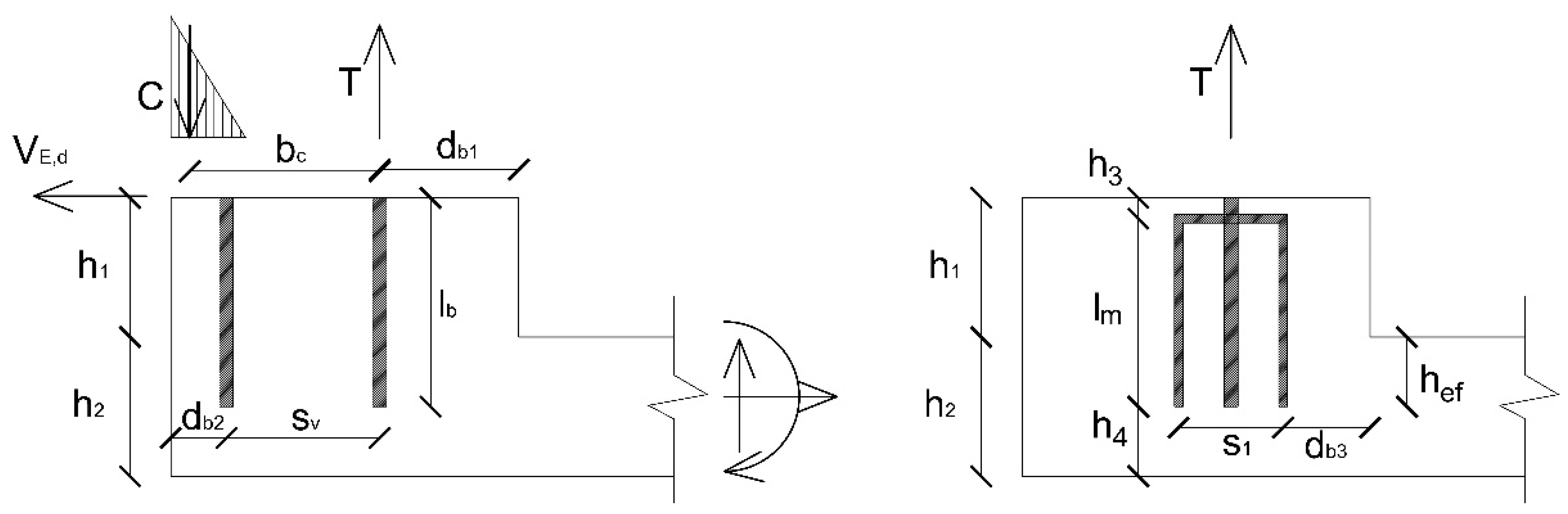
- The tensile load T applied to the two rear bars will be transferred to the concrete corbel and the additional U-shaped rebars;
- The shear load VE,d, applied to the two rear bars, will be transferred to the concrete corbel and to the transversal reinforcement (i.e., the existing stirrups);
- The compression load C generated by the steel plate will be spread into the concrete.
4.1. Strut and Tie Model: Load Transfer to the U-Shaped Rebars
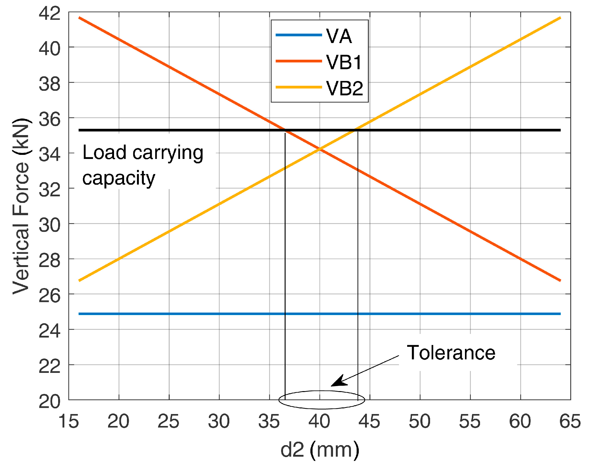
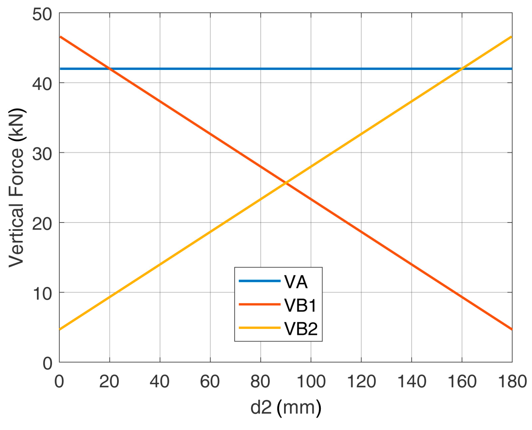
- The transfer length did not affect the vertical force in the U-shaped rebars and affected only the horizontal force, which increased with the transfer length. The design of the U-shaped rebars considered in this study (diameter 12 mm, B450C) was always satisfied for every position of the bars and for every practical value of the nodal region radius t. It was assumed that the transfer length of the bar could vary from a minimum value Lbd,min = 256.7 mm, as determined in accordance with Eurocode 2 [18], up to a maximum value Lbd,max = 340 mm, which corresponded to the total embedment depth of the bar below the plane of installation of the U-Shaped rebars. The distance between bars and U-shaped rebars must be in the range between 16 and 64 mm, which accounts for the spacing of the steel elements and the other constraints related to their diameters;
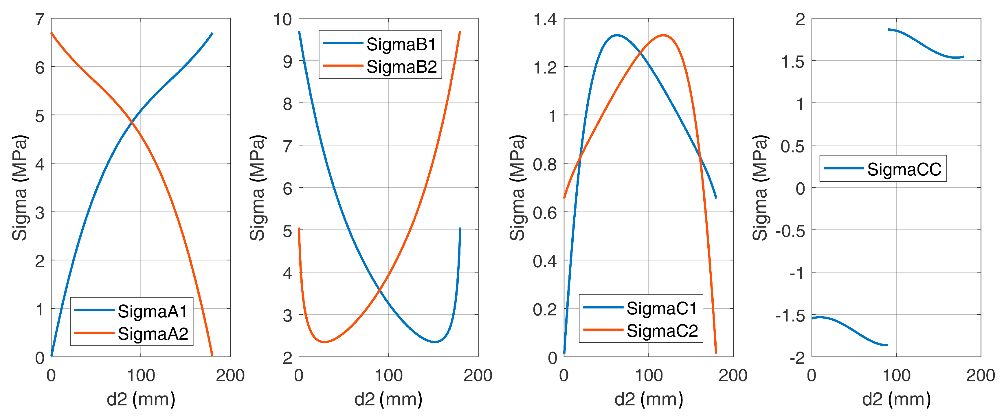
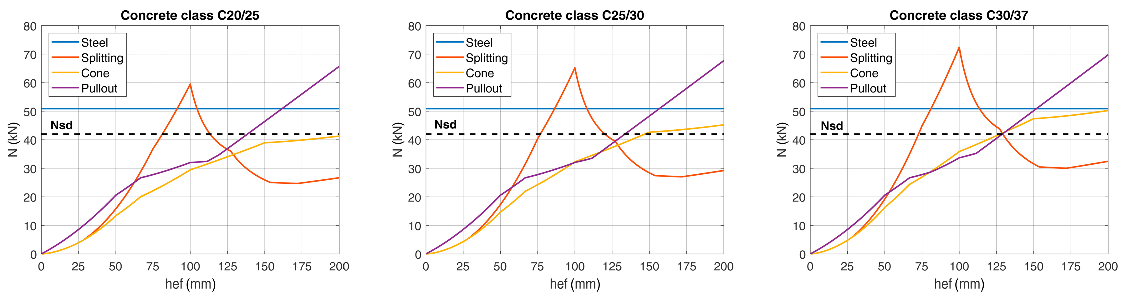
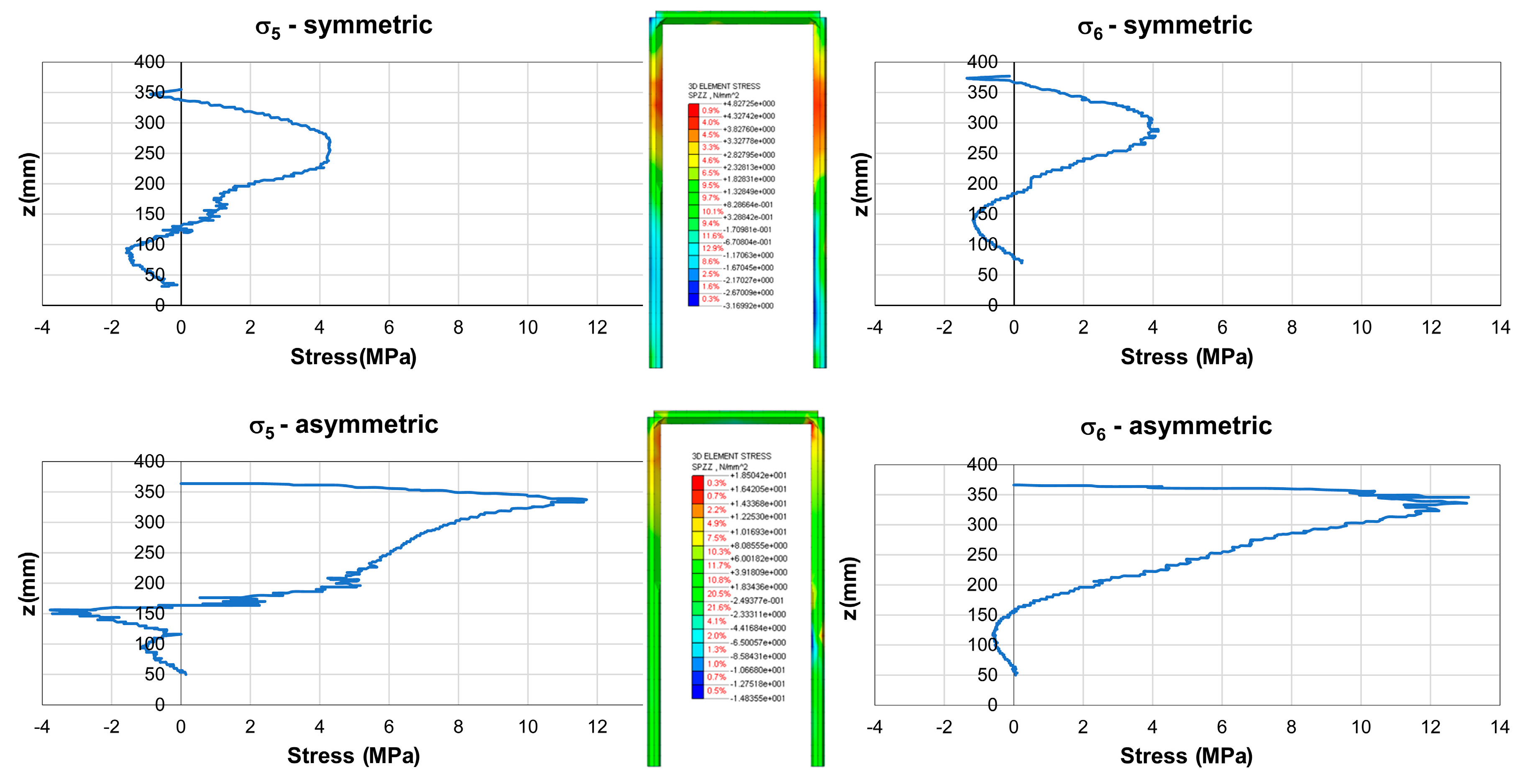
- The stresses in the concrete struts were always below 12 MPa. Thus, even when using a low strength concrete class (C20/25, as for the tested specimens), the concrete struts never failed;
- The 3D geometry of the model allowed the definition of the angles between the concrete struts and the steel elements. While Eurocode 2 [18] did not suggest any limit for these angles, lower bound limits should be defined. Indeed, an excessively small angle led to a non-reliable force transfer mechanism between concrete and steel and potential problems for the compatibility of concrete’s deformations. The lower limit of these angles was assumed to be 25° as per ACI 318-14 [35];
- The model shows that the load transfer mechanism from the post-installed bars to the U-shaped rebars could develop properly, regardless of the assumed length of the nodal region t and of the distance between bars and U-shaped rebars.
4.2. Strut and Tie Model: Anchoring of the U-Shaped Rebars
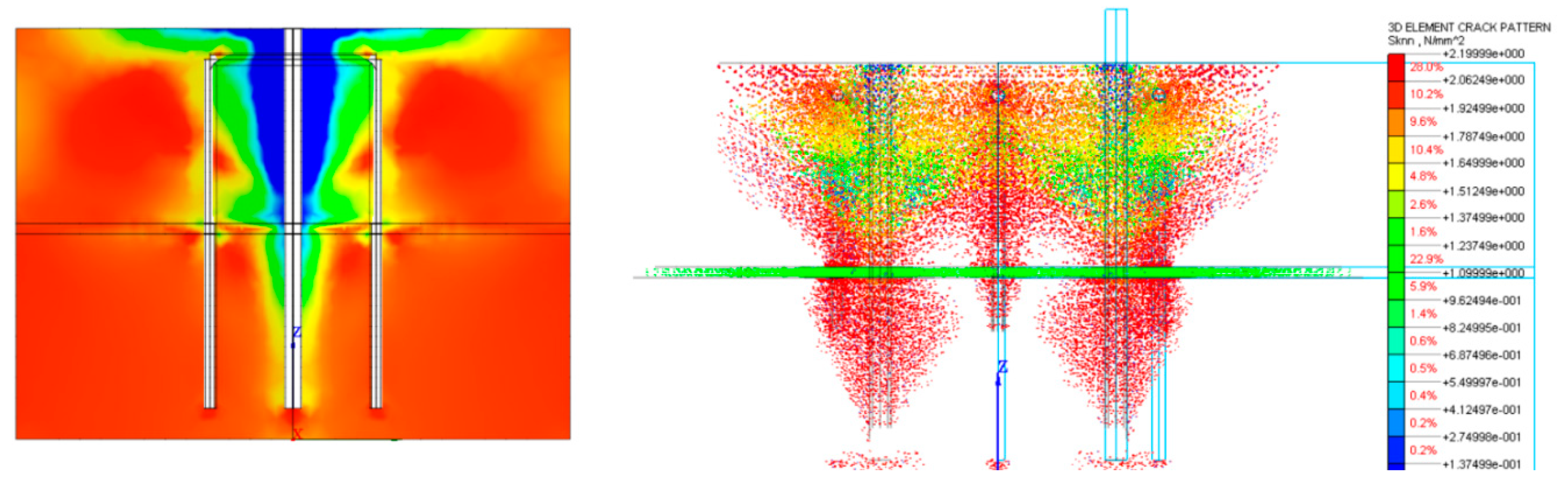
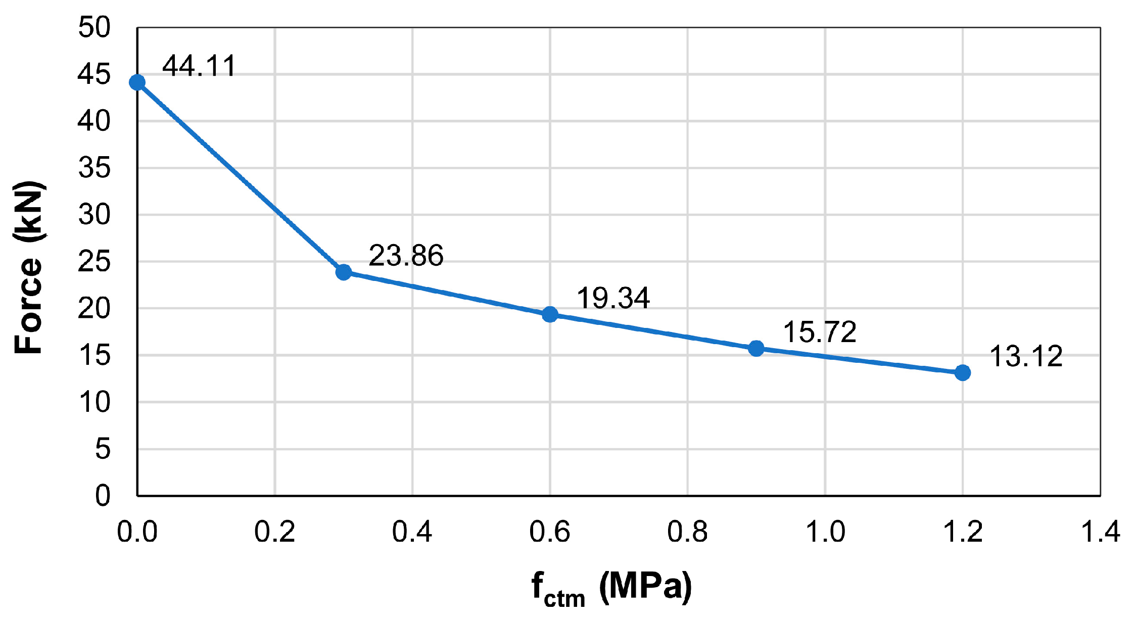
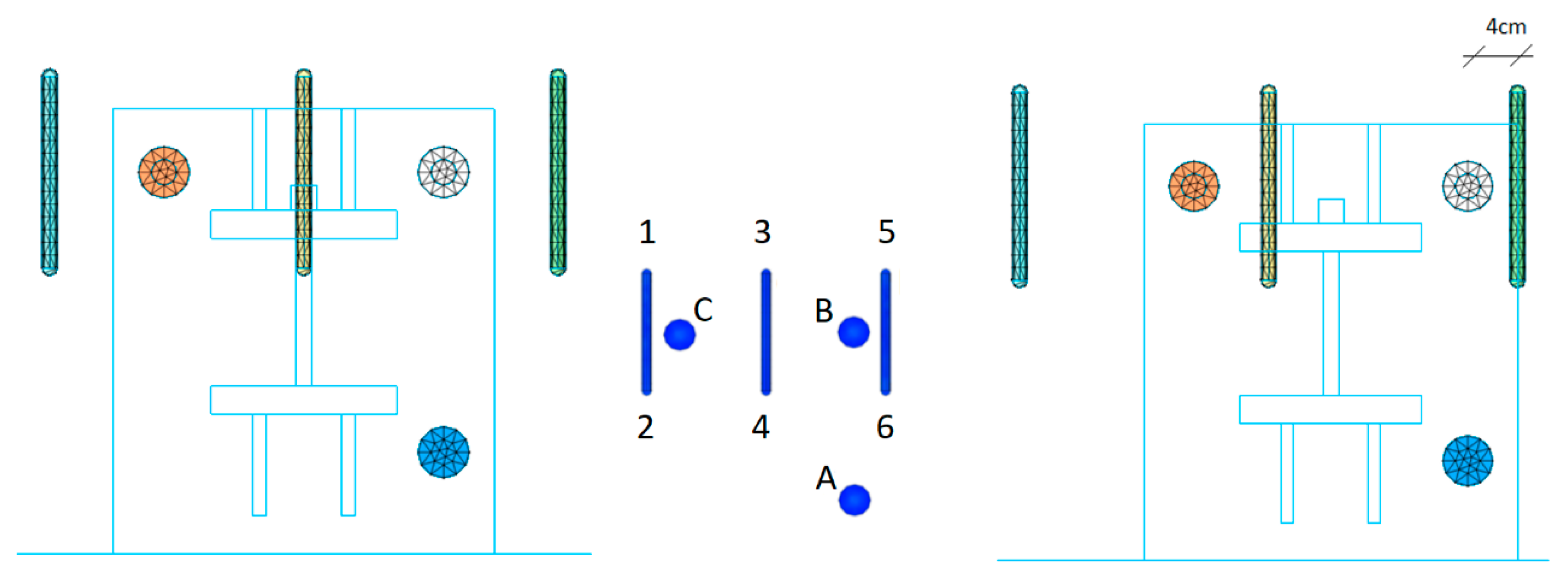
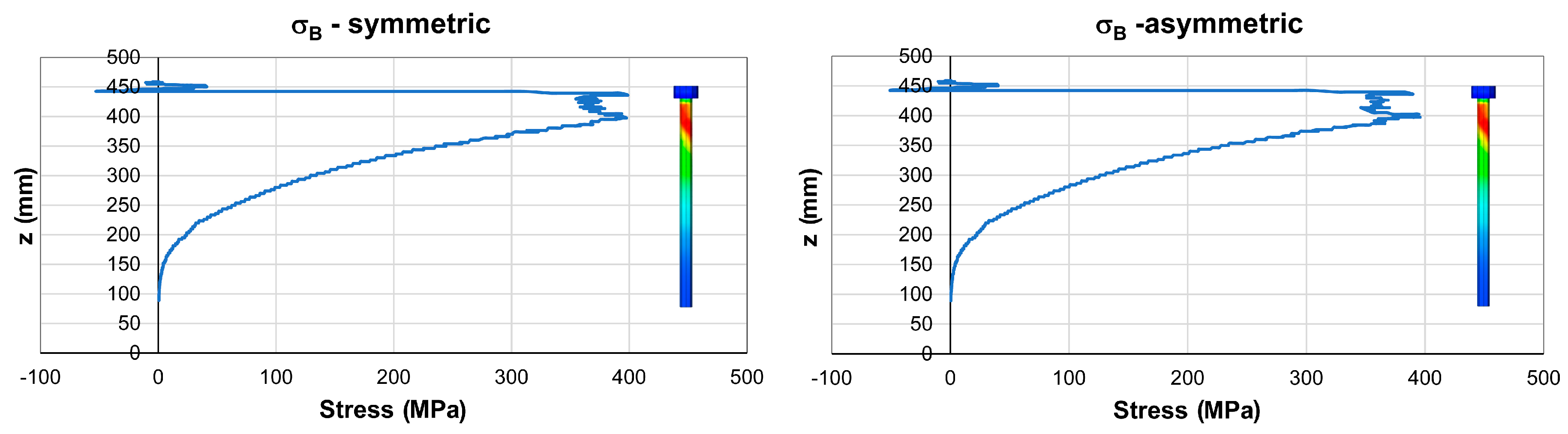
4.3. Numerical Analysis
5. Design Optimization
5.1. Analytical Approach
5.2. Numerical Approach
6. Conclusions
Author Contributions
Funding
Acknowledgments
Conflicts of Interest
References
- Eligehausen, R.; Mallée, R.; Silva, J. Anchorage in Concrete Construction; Ernst&Sohn: Hoboken, NJ, USA, 2006. [Google Scholar]
- Guerreiro, J.; Gago, A.S.; Ferreira, J.; Proença, J. An innovative anchoring system for old masonry buildings. J. Build. Eng. 2017, 13, 184–195. [Google Scholar] [CrossRef]
- Gesoglu, M.; Ozturan, T.; Ozel, M.; Guneyisi, E. Tensile behavior of post-installed anchors in plain and steel fiber reinforced normal and high-strength concretes. ACI Struct. J. 2005, 102, 224–231. [Google Scholar]
- Cattaneo, S. Wedge-type expansion anchors in high performance concrete. ACI Struct. J. 2007, 104, 191–198. [Google Scholar]
- Gurbuz, T.; Ilki, A. Pullout performance of fully and partially bonded retrofit anchors in low strength concrete. ACI Struct. J. 2011, 108, 61–70. [Google Scholar]
- Delhomme, F.; Brun, M. Pullout Tests on Post-installed Bonded Anchors in Ultra-high Performance Fiber Reinforced Concrete. Struct. Eng. Int. 2019, 29, 1–8. [Google Scholar] [CrossRef]
- Eligehausen, R.; Cook, R.A.; Appl, J. Behavior and design of adhesive bonded anchors. ACI Struct. J. 2006, 103, 822–831. [Google Scholar]
- Johnson, T.P.; Dowell, R.K. Evaluation of the overstrength factor for nonstructural component anchorage into concrete via dynamic shaking table tests. J. Build. Eng. 2017, 11, 205–215. [Google Scholar] [CrossRef]
- Johnson, T.P.; Dowell, R.K.; Silva, J.F. A review of code seismic demands for anchorage of nonstructural component. J. Build. Eng. 2016, 5, 249–253. [Google Scholar] [CrossRef]
- Cook, R.A.; Konz, R.C. Factors Influencing Bond Strength of Adhesive Anchors. ACI Struct. J. 2001, 98, 76–86. [Google Scholar]
- Grosser, P.; Fuchs, W.; Eligehausen, R. A field study of adhesive anchor installations. Concr. Int. 2011, 33, 57–63. [Google Scholar]
- González, F.; Fernández, J.; Agranati, G.; Villanueva, P. Influence of construction conditions on strength of post installed bonded anchors. Constr. Build. Mater. 2018, 165, 272–283. [Google Scholar] [CrossRef]
- Cattaneo, S.; Locatelli, A.; Rago, D. Reliability of bonded anchors with different installation techniques: Experimental assessment. Asian J. Civ. Eng. 2019, 20, 681–692. [Google Scholar] [CrossRef]
- Liu, M.; Frangopol, D.M. Optimizing Bridge Network Maintenance Management under Uncertainty with Conflicting Criteria: Life-Cycle Maintenance, Failure, and User Costs. J. Struct. Eng. 2006, 132, 1835–1845. [Google Scholar] [CrossRef]
- Yehia, S.; Abudayyeh, O.; Fazal, I.; Randolph, D. A decision support system for concrete bridge deck maintenance. Adv. Eng. Softw. 2008, 39, 202–210. [Google Scholar] [CrossRef]
- Charney, F.A.; Pal, K.; Silva, J. Recommended procedures for development and splicing of post-installed bonded reinforcing bars in concrete structures. ACI Struct. J. 2013, 110, 437–446. [Google Scholar] [CrossRef]
- Kunz, J.; Hamad, B.S.; Al Hammoud, R. Evaluation of Bond Strength of Bonded-In or Post-Installed Reinforcement. ACI Struct. J. 2006, 103, 207. [Google Scholar] [CrossRef]
- CEN. EN1992-1-1+AC. Eurocode 2: Design of Concrete Structures-Part 1-1: General Rules and Rules for Buildings; CEN: Brussels, Belgium, 2010. [Google Scholar]
- CEN. EN1992-4. Eurocode 2-Design of Concrete Structures-Part 4: Design of Fastenings for Use in Concrete; CEN: Brussels, Belgium, 2018. [Google Scholar]
- fib Bulletin. Bulletin 58: Design of Anchorages in Concrete; fib Bulletin: Lausanne, Switzerland, 2011. [Google Scholar]
- EOTA. EAD330087-00-0601 Systems for Post-Installed Rebar Connections with Mortar; EOTA: Brussels, Belgium, 2018. [Google Scholar]
- EOTA. EAD 330499-00-0601 Bonded Fasteners for Use in Concrete; EOTA: Brussels, Belgium, 2017. [Google Scholar]
- EOTA. TR029 Design of Bonded Anchors; EOTA: Brussels, Belgium, 2010. [Google Scholar]
- Mitchell, G.; Strahota, M.T.; Gokani, V.; Picón, R.; Yang, S.; Klingner, R.E.; Williamson, E.B. Performance of Retrofit Highway Barriers with Mechanical Anchors. ACI Struct. J. 2010, 107, 381–389. [Google Scholar]
- Rodriguez, M.; Lotze, D.; Gross, J.H.; Zhang, Y.G.; Klingner, R.E.; Graves, H.L. Dynamic Behavior of Tensile Anchors to Concrete. ACI Struct. J. 2001, 98, 511–524. [Google Scholar]
- Ahmed, L.T.; Braimah, A. Tensile behaviour of adhesive anchors under different strain rates. Eng. Struct. 2019, 192, 113–125. [Google Scholar] [CrossRef]
- Mahrenholtz, C.; Eligehausen, R. Dynamic performance of concrete undercut anchors for Nuclear Power Plants. Nucl. Eng. Des. 2013, 265, 1091–1100. [Google Scholar] [CrossRef]
- Russo, G.; Venir, R.; Pauletta, M.; Somma, G. Reinforced Concrete Corbels—Shear Strength Model and Design Formula. ACI Struct. J. 2006, 103, 3–10. [Google Scholar] [CrossRef]
- EOTA. TR048 Details of Tests for Post-Installed Fasteners in Concrete; EOTA: Brussels, Belgium, 2016. [Google Scholar]
- CEN. EN12390-3 Testing Hardened Concrete—Part 3: Compressive Strength of Test Specimens; CEN: Brussels, Belgium, 2009. [Google Scholar]
- EOTA. ETA 16/0143 Injection System Hilti HIT-RE 500 V3; EOTA: Brussels, Belgium, 2016. [Google Scholar]
- Ministero delle Infrastrutture e dei Trasporti. Aggiornamento delle Norme Tecniche per le Costruzioni (NTC2018); Ministero delle Infrastrutture e dei Trasporti: Rome, Italy, 2018. [Google Scholar]
- Mahrenholtz, C.; Eligehausen, R.; Reinhardt, H.W. Design of post-installed reinforcing bars as end anchorage or as bonded anchor. Eng. Struct. 2015, 100, 645–655. [Google Scholar] [CrossRef]
- Cattaneo, S.; Crespi, P.; Locatelli, A.; Rago, D. Safety barriers for bridges. In Report Dept. ABC; Politecnico di Milano: Milan, Italy, 2018. [Google Scholar]
- ACI Committee 318. Building Code Requirements for Structural Concrete (ACI 318-14) and Commentary on Building Code Requirements for Structural Concrete (ACI 318R-14); ACI Committee 318: Farmington Hills, MI, USA, 2014. [Google Scholar]
- MidasFEA. Analysis and Algorithm Manual; MidasFEA: Seongnam-si, Korea, 2015. [Google Scholar]
- Cattaneo, S.; Giussani, F. Shear behaviour of R.C. beams with water-stop joints. Eng. Struct. 2013, 56, 1775–1786. [Google Scholar] [CrossRef]
- HILTI. Profis Engineering n.d; HILTI: Schaan Liechtenstein, Germany, 2018. [Google Scholar]


| Fixture | Bars | U-Shaped Rebars | Materials |
|---|---|---|---|
| b = 300 mm | ∅b = 20 mm | ∅r = 12 mm | Ec = 30 GPa |
| h = 350 mm | db1 = 200 mm | s1 = 150 mm | Es = 210 GPa |
| sh = 220 mm | db2 = 80 mm | s2 = 150 mm | fyk,rebar = 450 MPa |
| - | h1 = 200 mm | db3 = 125 mm | fyk,bar = 500 MPa |
| - | h2 = 200 mm | h3 = 30 mm | fcd = 20 MPa |
| - | sv = 220 mm | h4 = 30 mm | εc1 = 2‰ |
| - | bc = 300 mm | hef = 170 mm | εsy = 1.956‰ |
| - | lb = 370 mm | lm = 340 mm | - |
| Element | Symmetric | Asymmetric | Difference | |||
|---|---|---|---|---|---|---|
| σ (MPa) | F (kN) | σ (MPa) | F (kN) | σ (MPa) | F (kN) | |
| A | 34.66 | 10.86 | 33.94 | 10.66 | 1.38 | 0.43 |
| B | 401.88 | 98.64 | 401.19 | 98.86 | 0.69 | 0.22 |
| C | 395.17 | 95.52 | 395.03 | 95.58 | 0.15 | 0.06 |
| 1 | 4.31 | 0.34 | 2.33 | 0.18 | 4.35 | 0.49 |
| 2 | 3.77 | 0.29 | 6.12 | 0.48 | 0.92 | 0.52 |
| 3 | 3.97 | 0.31 | 8.78 | 0.69 | 4.81 | 0.54 |
| 4 | 3.97 | 0.31 | 5.57 | 0.44 | 1.60 | 0.18 |
| 5 | 4.21 | 0.33 | 11.67 | 0.92 | 7.46 | 0.84 |
| 6 | 4.19 | 0.33 | 13.05 | 1.03 | 8.86 | 1.00 |
© 2019 by the authors. Licensee MDPI, Basel, Switzerland. This article is an open access article distributed under the terms and conditions of the Creative Commons Attribution (CC BY) license (http://creativecommons.org/licenses/by/4.0/).
Share and Cite
Cattaneo, S.; Crespi, P. Response of Connections between Concrete Corbels and Safety Barriers. Materials 2019, 12, 4103. https://doi.org/10.3390/ma12244103
Cattaneo S, Crespi P. Response of Connections between Concrete Corbels and Safety Barriers. Materials. 2019; 12(24):4103. https://doi.org/10.3390/ma12244103
Chicago/Turabian StyleCattaneo, Sara, and Pietro Crespi. 2019. "Response of Connections between Concrete Corbels and Safety Barriers" Materials 12, no. 24: 4103. https://doi.org/10.3390/ma12244103
APA StyleCattaneo, S., & Crespi, P. (2019). Response of Connections between Concrete Corbels and Safety Barriers. Materials, 12(24), 4103. https://doi.org/10.3390/ma12244103