Heat Treatment, Impact Properties, and Fracture Behaviour of Ti-6Al-4V Alloy Produced by Powder Compact Extrusion


Abstract
1. Introduction
2. Material and Methods
3. Results
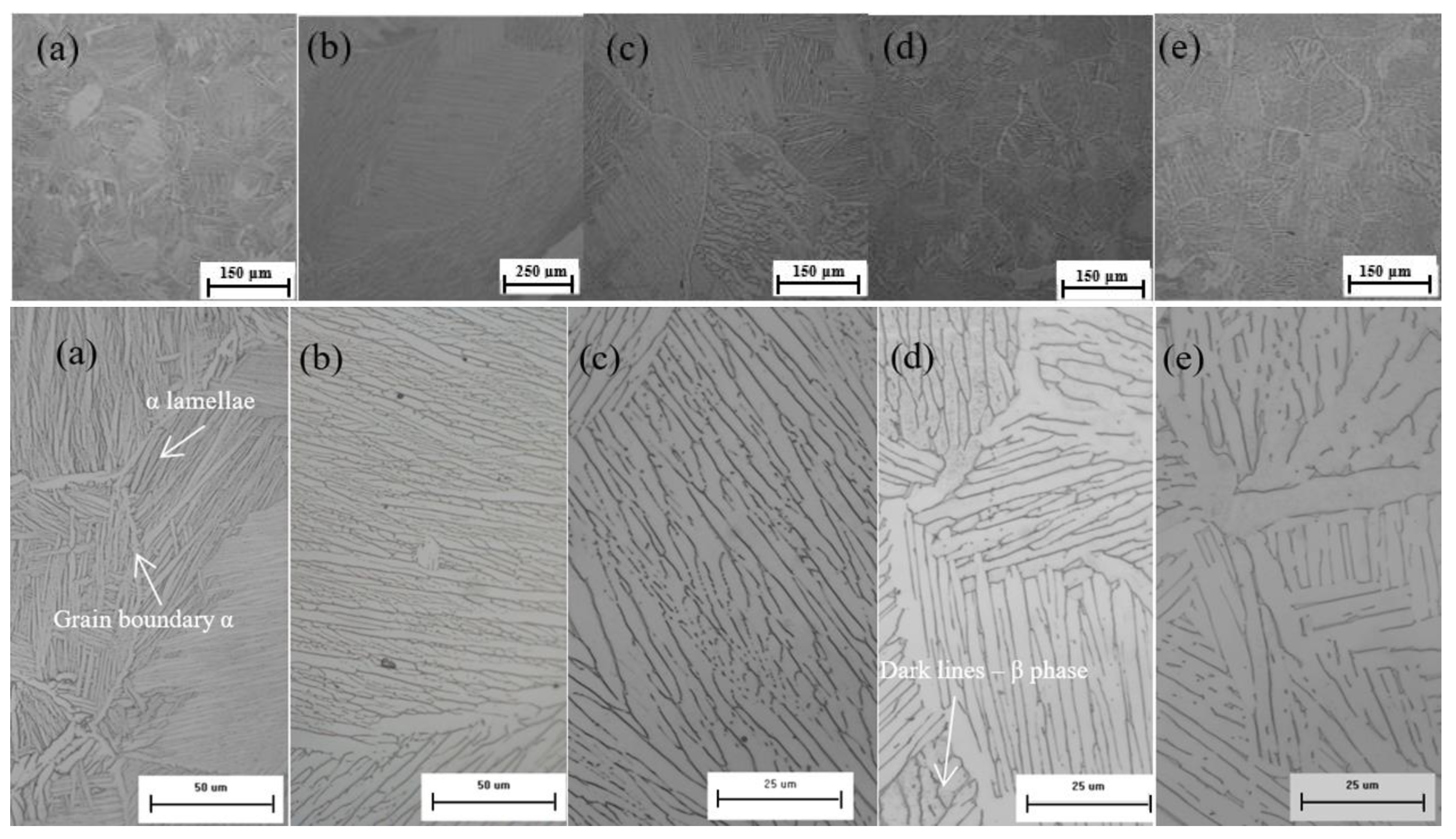
3.1. Microstructure
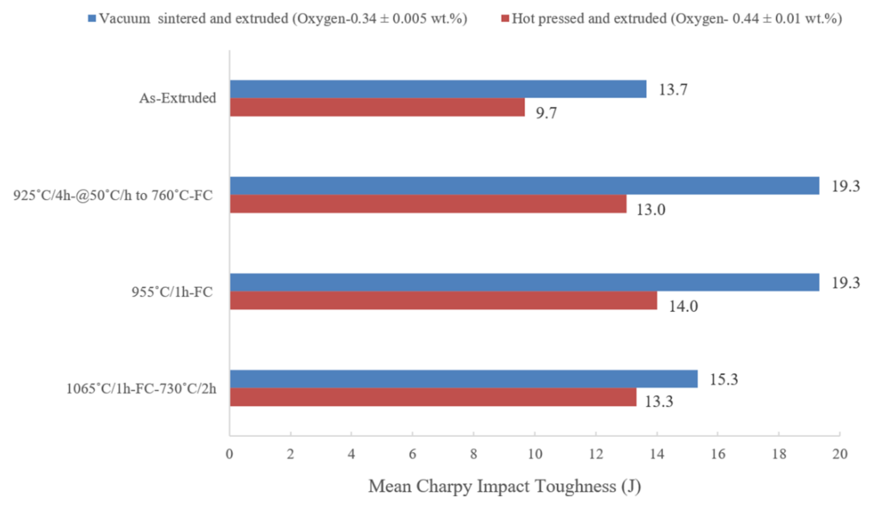
3.2. Impact Properties
3.3. Fracture Behaviour of Charpy Impact Specimens
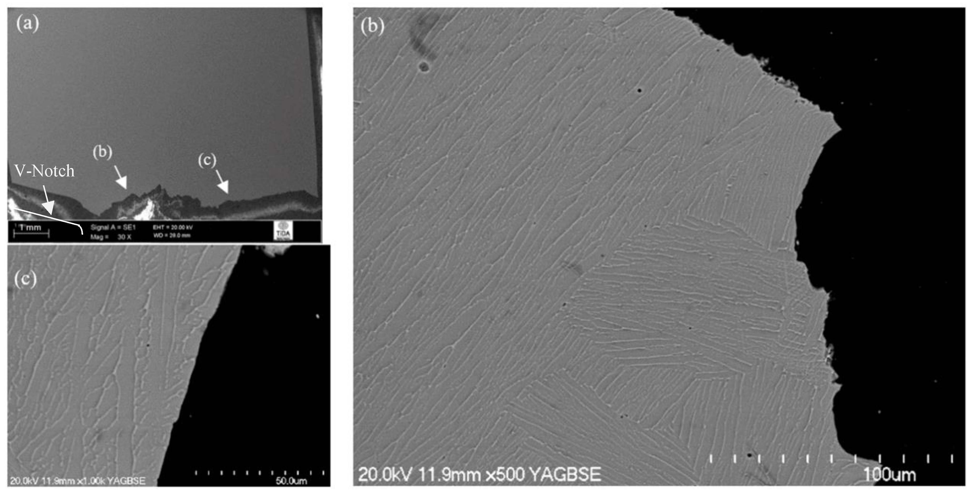
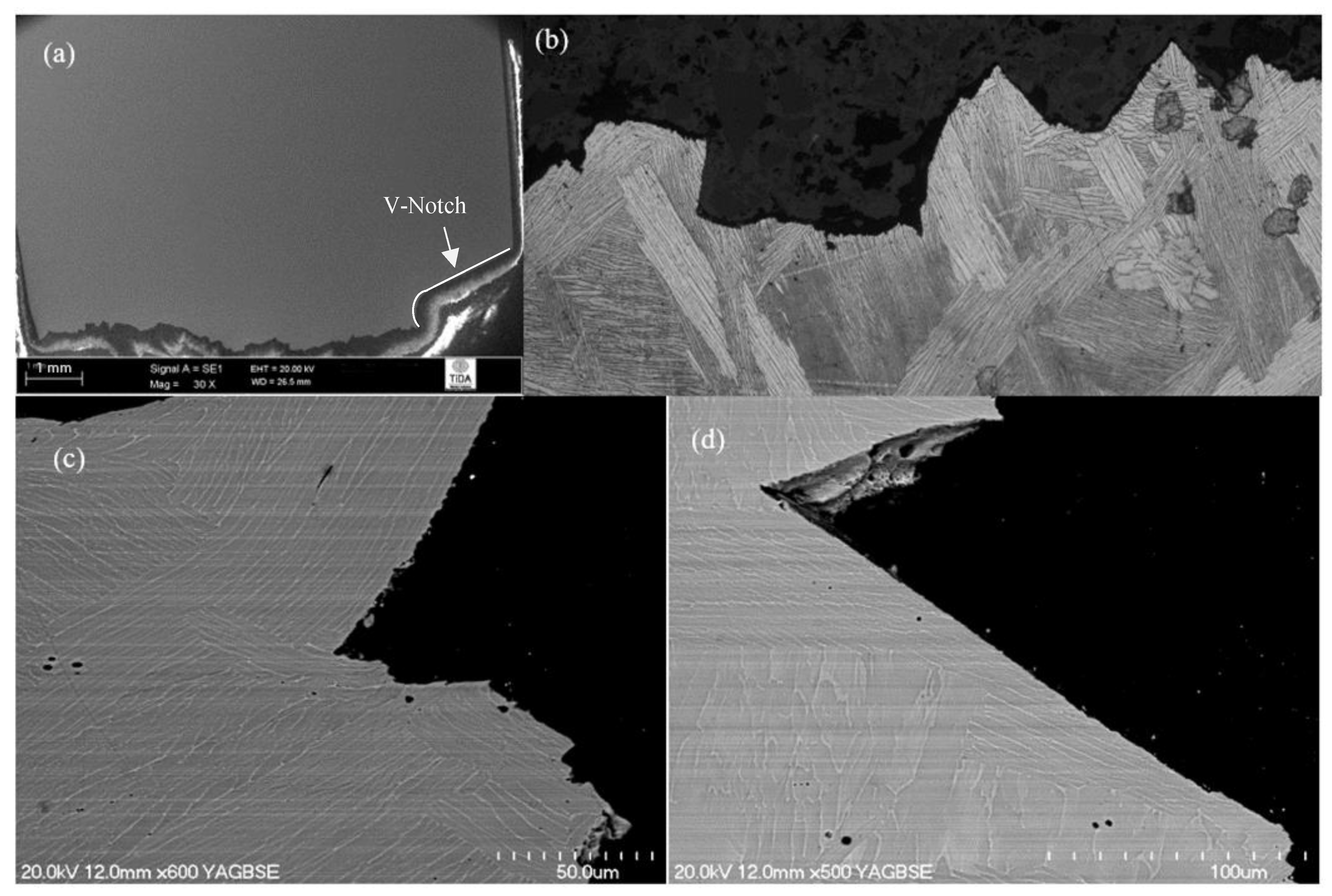
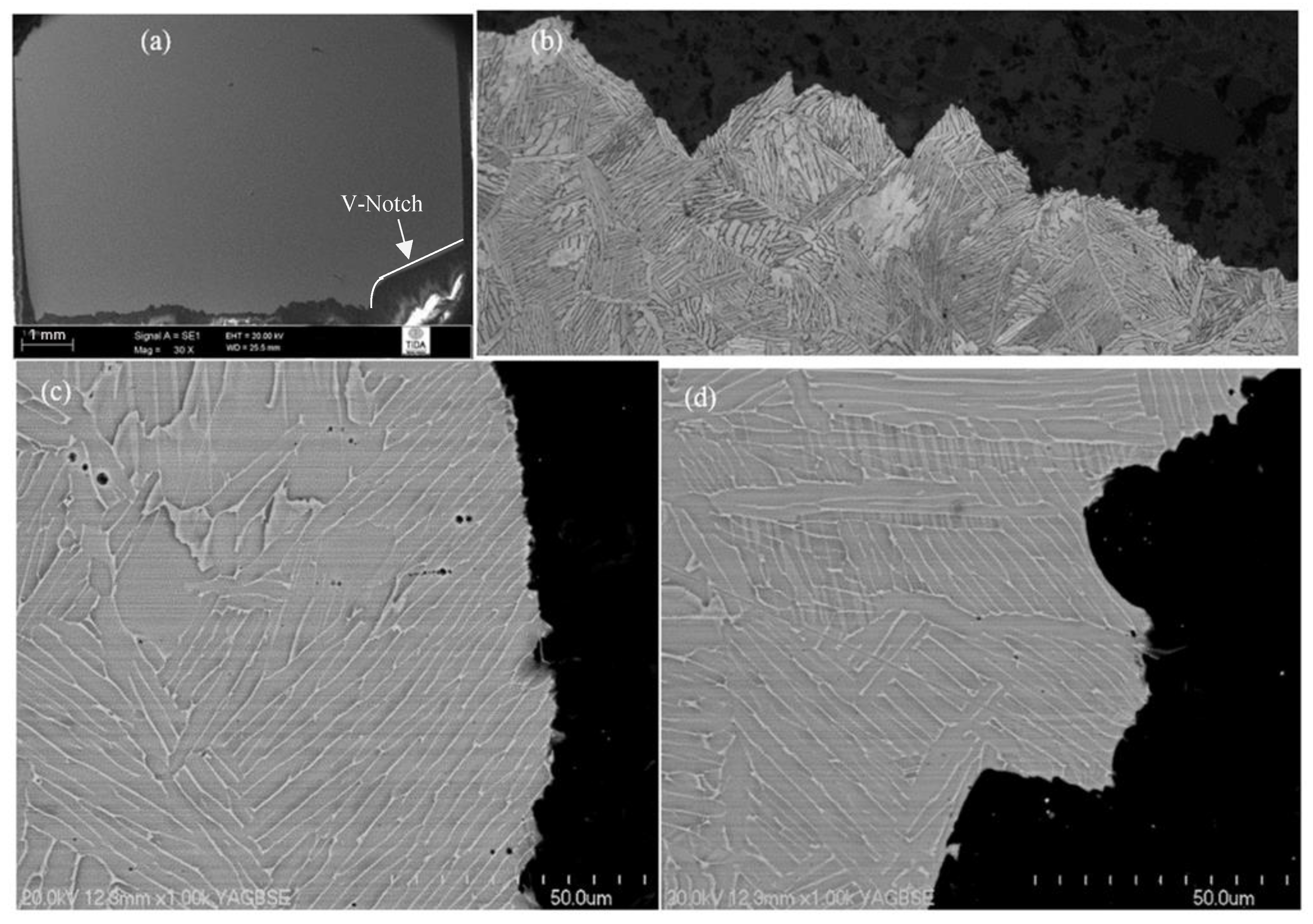
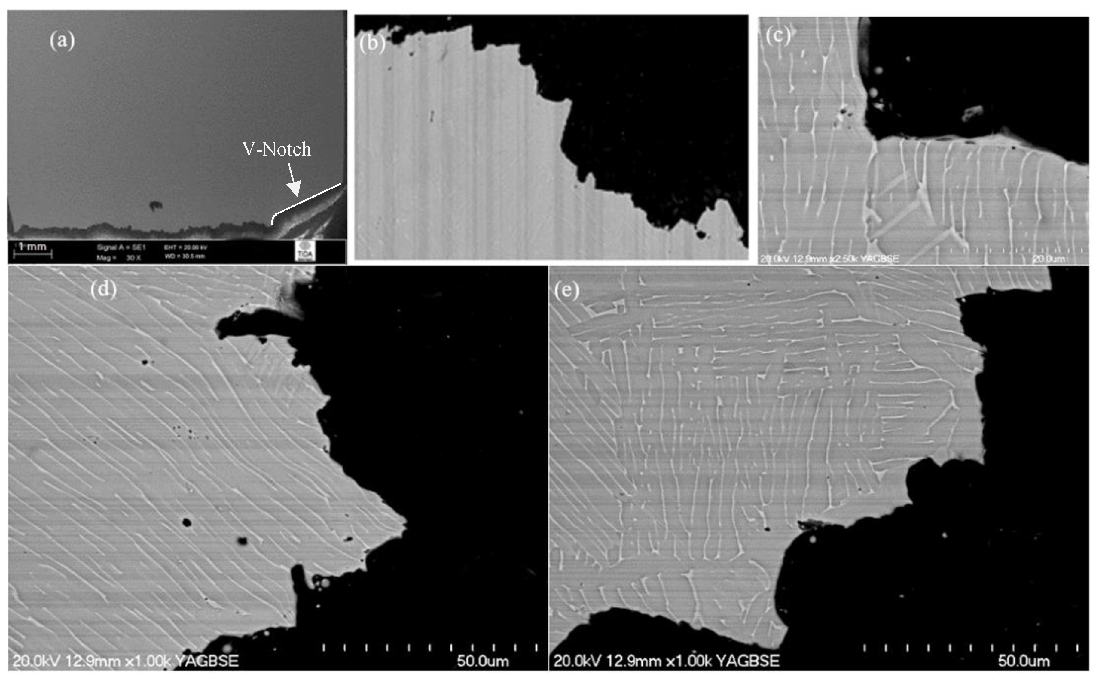
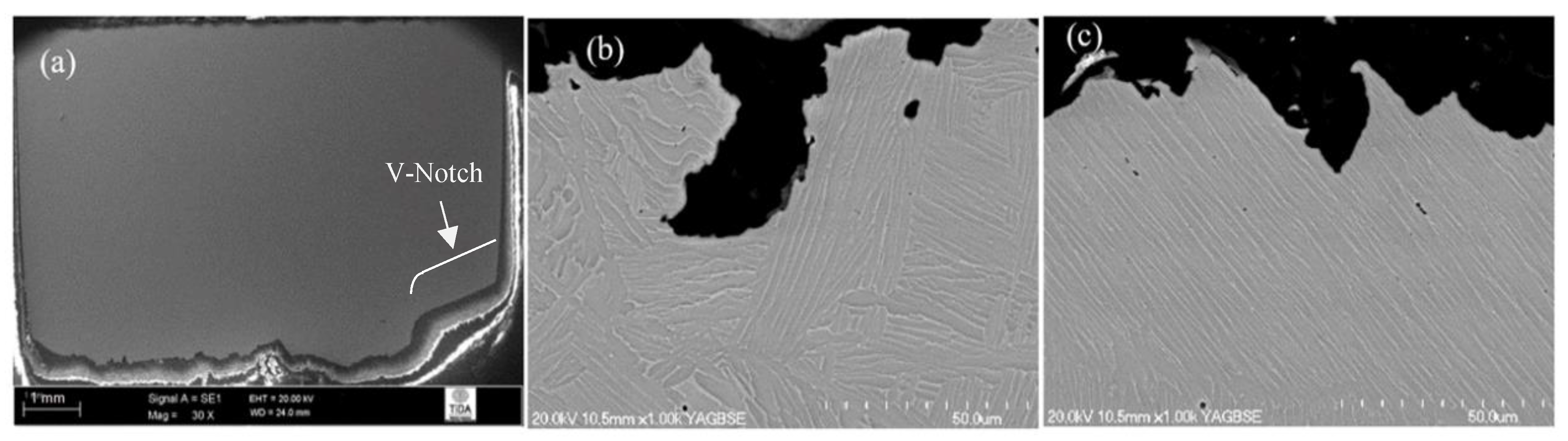
3.3.1. Crack Propagation Behaviour
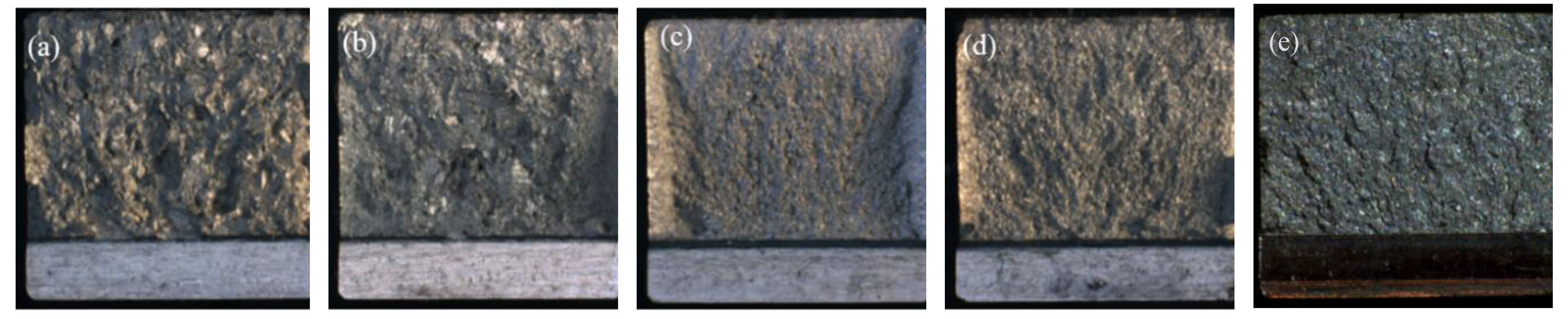
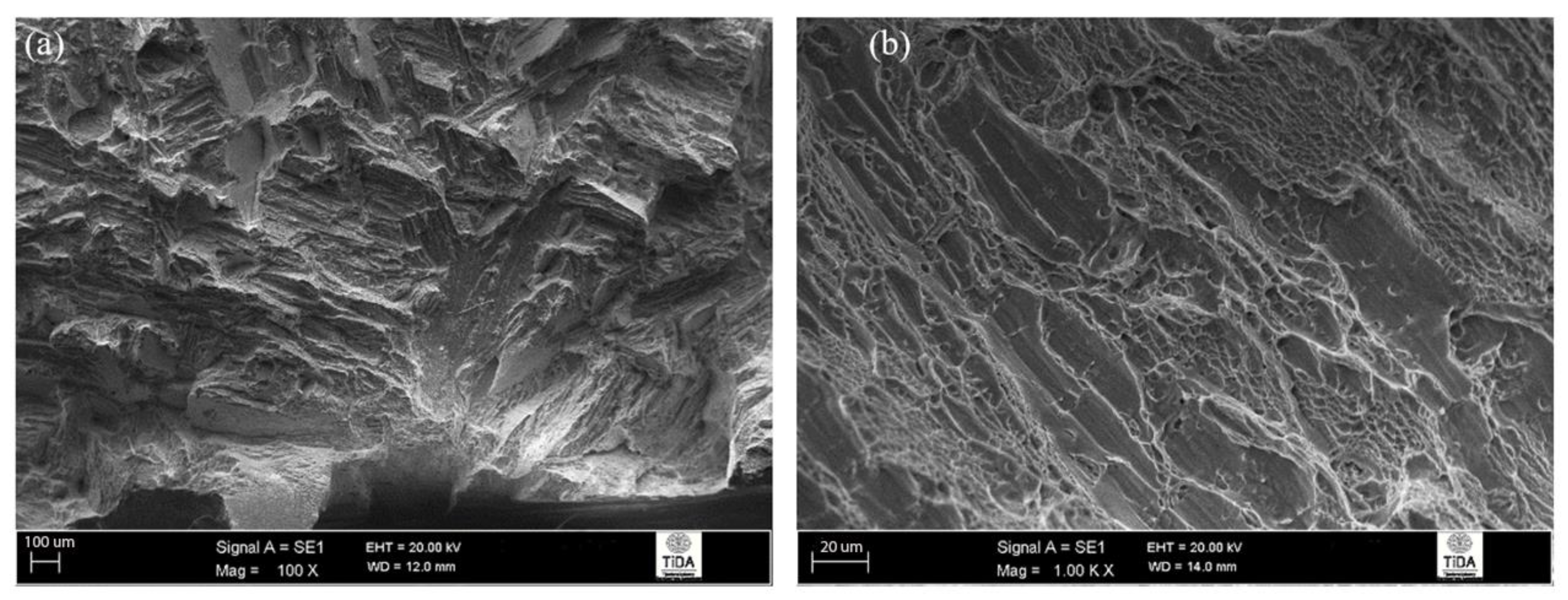
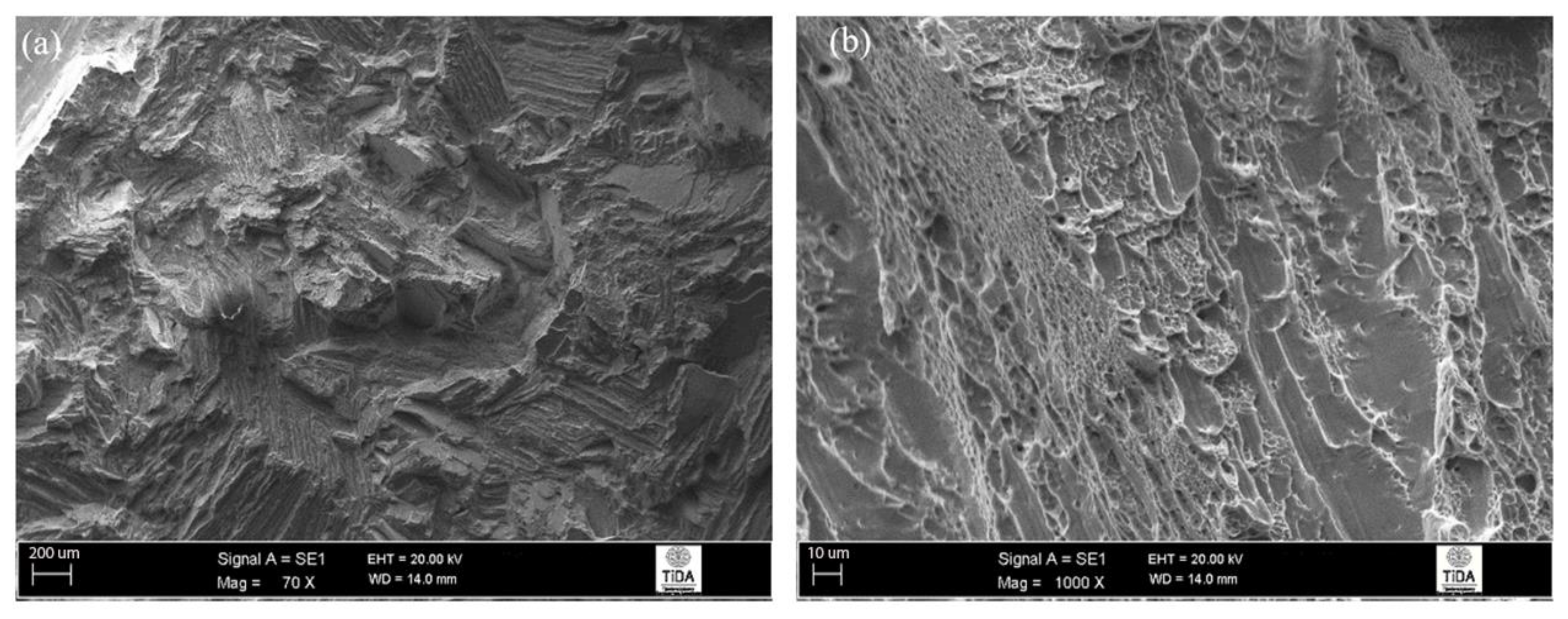
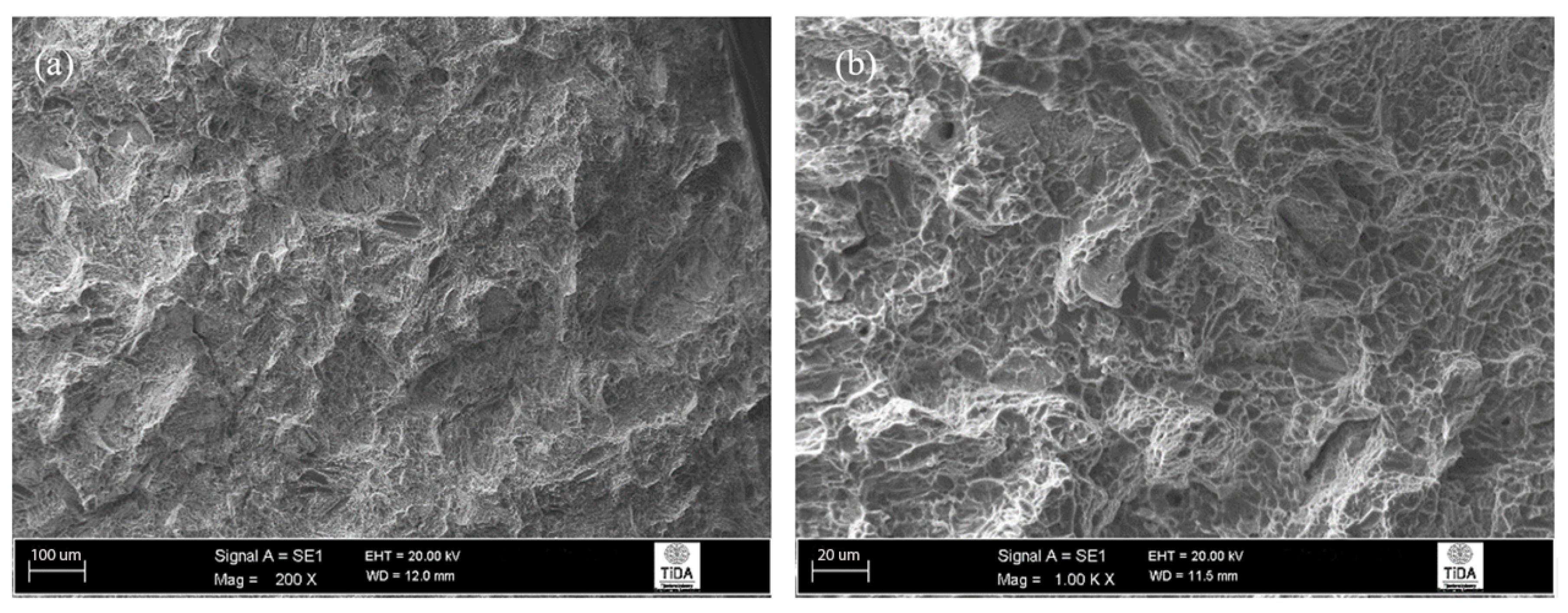
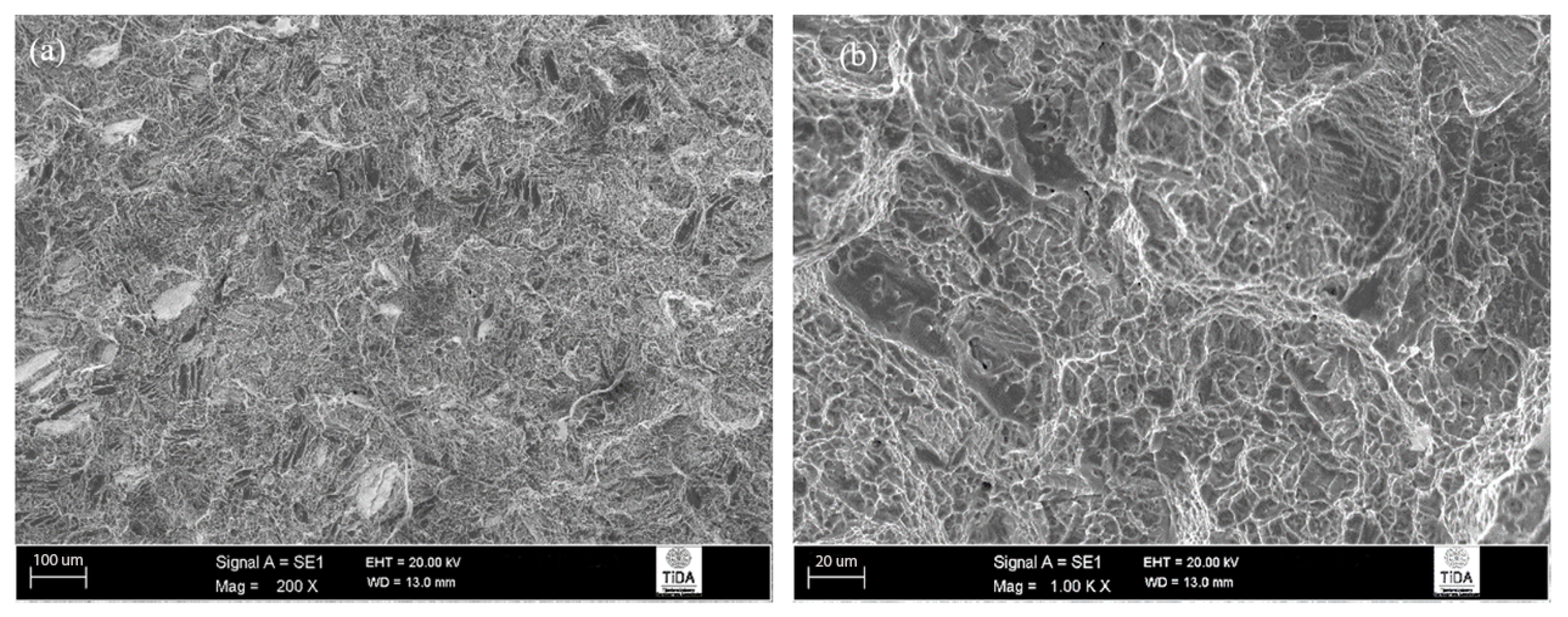
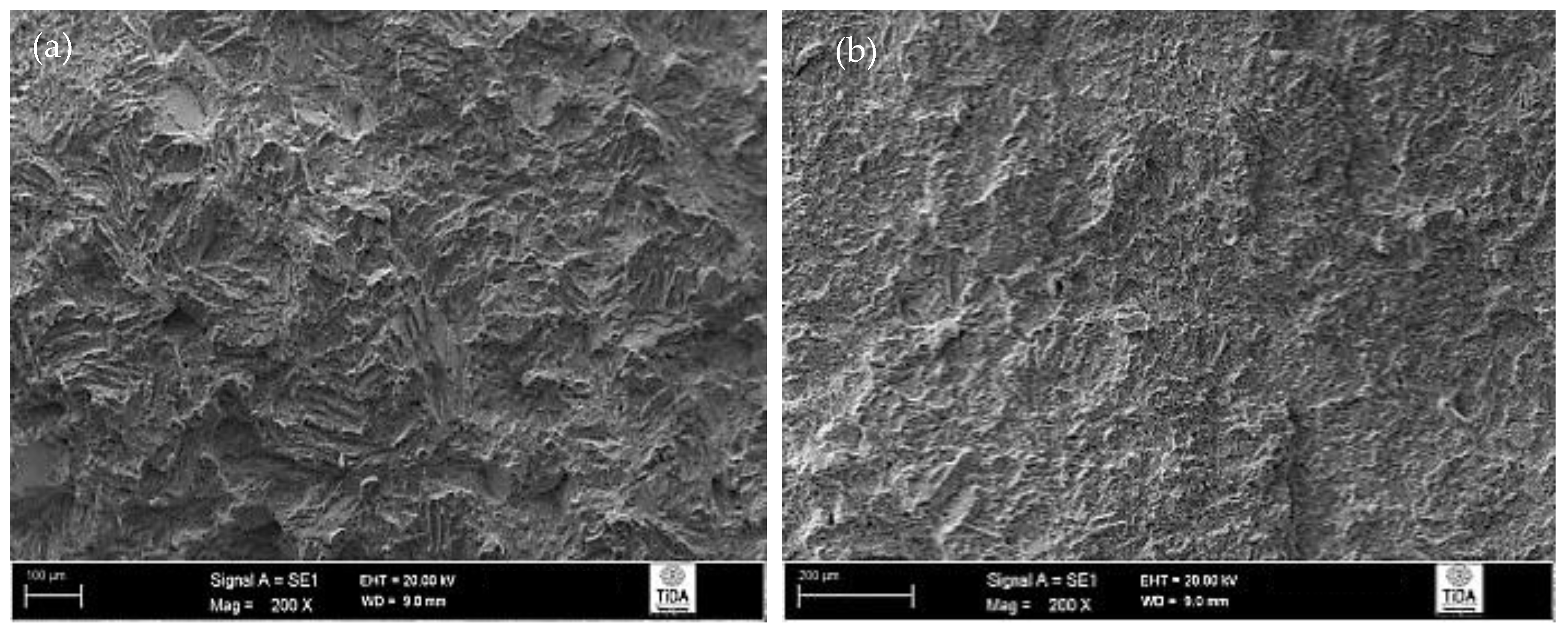
3.3.2. Fracture Surfaces
4. Discussion
4.1. Microstructure Comparison
4.2. Comparison of Impact Properties with Literature
4.3. Comments about Complex Fracture Behaviour in PM materials
5. Conclusions
Author Contributions
Funding
Acknowledgments
Conflicts of Interest
References
- Boyer, R.R.; Welsch, G.; Collings, E.W. Materials Properties Handbook: Titanium Alloys; ASM International, Materials Park: Cleveland, OH, USA, 1994. [Google Scholar]
- Lutjering, G.; Williams, J.C. Titanium, 2nd ed.; Springer: Berlin/Heidelberg, Germany, 2007. [Google Scholar]
- Donachie, M.J. Titanium: A Technical Guide, 2nd ed.; ASM International, Materials Park: Cleveland, OH, USA, 2000. [Google Scholar]
- Reda, R.; Nofal, A.; Hussein, A.-H. Effect of single and duplex stage heat treatment on the microstructure and mechanical properties of cast Ti-6Al-4V alloy. Metallogr. Microstruct. Anal. 2013, 2, 388–393. [Google Scholar] [CrossRef]
- Reda, R.; Nofal, A.; Hussein, A. Effect of quenching temperature on the mechanical properties of cast Ti–6Al–4V alloy. J. Metall. Eng. 2013, 2, 48–54. [Google Scholar]
- Meyer, L.W.; Krüger, L.; Sommer, K.; Halle, T.; Hockauf, M. Dynamic strength and failure behavior of titanium alloy Ti-6Al-4V for a variation of heat treatments. Mech. Time Depend. Mater. 2008, 12, 237–247. [Google Scholar] [CrossRef]
- Zherebtsov, S.; Kudryavtsev, E.; Kostjuchenko, S.; Malysheva, S.; Salishchev, G. Strength and ductility-related properties of ultrafine grained two-phase titanium alloy produced by warm multiaxial forging. Mater. Sci. Eng. A-Struct. Mater. Prop. Microstruct. Process. 2012, 536, 190–196. [Google Scholar] [CrossRef]
- Kwon, J.D.; Bae, Y.T.; Choi, S.J. The effect of microstructure on mechanical behaviour for titanium alloy (Ti-6Al-4V). Int. J. Mod. Phys. B Condens. Matter Phys. Stat. Phys. At. Mol. Opt. Phys. 2003, 17, 1297–1303. [Google Scholar] [CrossRef]
- Buirette, C.; Huez, J.; Gey, N.; Vassel, A.; Andrieu, E. Study of crack propagation mechanisms during Charpy impact toughness tests on both equiaxed and lamellar microstructures of Ti-6Al-4V titanium alloy. Mater. Sci. Eng. A-Struct. Mater. Prop. Microstruct. Process. 2014, 618, 546–557. [Google Scholar] [CrossRef]
- Titanium Alloy Guide. Available online: http://rtiintl.s3.amazonaws.com/RTI-Reports/tiguideWeb.pdf (accessed on 4 November 2015).
- Guo, R.; Xu, L.; Wu, J.; Yang, R.; Zong, B.Y. Microstructural evolution and mechanical properties of powder metallurgy Ti-6Al-4V alloy based on heat response. Mater. Sci. Eng. A-Struct. Mater. Prop. Microstruct. Process. 2015, 639, 327–334. [Google Scholar] [CrossRef]
- Yasa, E.; Deckers, J.; Kruth, J.P.; Rombouts, M.; Luyten, J. Experimental investigation of charpy impact tests on metallic SLM parts. In Innovative Developments in Design and Manufacturing: Advanced Research in Virtual and Rapid Prototyping; Bartolo, P.J.D., DeLemos, A.C.S., Pereira, A.M.H., Mateus, A.J.D., Mendes, A.L.A., DeMoura, C.S.M., Capela, C.A.B., DaSilva, C.S.G., Domingues, F.A.C., Bartolo, H., et al., Eds.; CRC: Boca Raton, FL, USA, 2010; pp. 207–214. [Google Scholar]
- Cvijovic, I.; Vilotijevic, M.; Milan, T.J. The influence of microstructural characteristics on the mechanical properties of Ti6Al4V alloy produced by the powder metallurgy technique. J. Serb. Chem. Soc. 2006, 71, 985–992. [Google Scholar]
- Bozic, D.; Sekulic, D.; Stasic, J.; Rajkovic, V.; Jovanovic, M.T. The influence of microstructural characteristics and contaminants on the mechanical properties and fracture topography of low cost Ti6Al4V alloy. Int. J. Mater. Res. 2008, 99, 1268–1274. [Google Scholar] [CrossRef]
- Titanium Ti-6Al-4V (Grade 5), Annealed. Available online: http://asm.matweb.com/search/SpecificMaterial.asp?bassnum=MTP641 (accessed on 4 November 2015).
- ASTM B988-13. Standard Specification for Powder Metallurgy (PM) Titanium and Titanium Alloy Structural Components; ASTM: West Conshohocken, PA, USA, 2013. [Google Scholar]
- Peter, W.H.; Chen, W.; Yamamoto, Y.; Dehoff, R.; Muth, T.; Nunn, S.D.; Kiggans, J.O.; Clark, M.B.; Sabau, A.S.; Gorti, S. Current status of Ti PM: Progress, opportunities and challenges. Key Eng. Mater. 2012, 520, 1–7. [Google Scholar] [CrossRef]
- McEldowney, D.J.; Tamirisakandala, S.; Miracle, D.B. Heat-treatment effects on the microstructure and tensile properties of powder metallurgy Ti-6Al-4V alloys modified with boron. Metall. Mater. Trans. A-Phys. Metall. Mater. Sci. 2010, 41A, 1003–1015. [Google Scholar] [CrossRef]
- Chandler, H. (Ed.) Heat Treater‘s Guide: Practices and Procedures for Nonferrous Alloys; ASM International, Materials Park: Cleveland, OH, USA, 1996. [Google Scholar]
- Henry, S.D.; Dragolich, K.S.; Dimatteo, N.D. (Eds.) Fatigue Data Book: Light Structural Alloys; ASM International, Materials Park: Cleveland, OH, USA, 1995. [Google Scholar]
- Jia, M.T.; Zhang, D.L.; Gabbitas, B.; Liang, J.M.; Kong, C. A novel Ti–6Al–4V alloy microstructure with very high strength and good ductility. Scr. Mater. 2015, 107, 10–13. [Google Scholar] [CrossRef]
- Wang, L.; Lang, Z.B.; Shi, H.P. Properties and forming process of prealloyed powder metallurgy Ti-6Al-4V alloy. Trans. Nonferrous Met. Soc. China 2007, 17, s639–s643. [Google Scholar]
- Singh, A.P.; Yang, F.; Torrens, R.; Gabbitas, B. The effect of heat treatment on the mechanical properties of Ti–6Al–4V alloy produced by consolidating a high impurity blended powder mixture using a combination of powder compact hot pressing and extrusion. J. Mater. Res. 2019, 34, 1426–1438. [Google Scholar] [CrossRef]
- Singh, A.P.; Yang, F.; Torrens, R.; Gabbitas, B. Solution treatment of Ti-6Al-4V alloy produced by consolidating blended powder mixture using a powder compact extrusion route. Mater. Sci. Eng. A-Struct. Mater. Prop. Microstruct. Process. 2018, 712, 157–165. [Google Scholar] [CrossRef]
- Singh, A.P.; Gabbitas, B.; Torrens, R.; Yang, F.; Mukhtar, A. Mechanical properties of Ti-6Al-4V rods produced by powder compact extrusion. In TMS 2014 Supplemental Proceedings; John Wiley & Sons: Hoboken, NJ, USA, 2014; p. 605. [Google Scholar]
- Singh, A.P.; Gabbitas, B.; Yang, F.; Torrens, R. Processing, Microstructure and High Strain Rate Behaviour of Ti-6Al-4V Alloy Produced from a Blended Mixture Using Powder Compact Extrusion. Key Eng. Mater. 2016, 704, 413–422. [Google Scholar] [CrossRef]
- Clark, E.P. Variable Oxidation & Defects in Ti-6Al-4V Material in Electron Beam Melting Additive Manufacturing. Master’s Thesis, University of Denver, Denver, CO, USA, 2017. [Google Scholar]


| Starting Powders | |||||
| Powders | Oxygen Content (wt.%) | Volume Fraction Below Particular (μm) | Particle Size | ||
| d(0.1) | d(0.5) | d(0.9) | |||
| HDH Ti | ~0.25 | 27.043 | 51.252 | 89.485 | −200 mesh |
| MA (60Al-40V) | ~0.61 | 28.384 | 53.460 | 91.167 | −250 mesh |
| Processing | |||||
| Process | Equipment | Description | |||
| Blending/roller mixing | Horizontal rollers | 450 g of HDH Ti + 50 g of MA (60Al-40V) were mixed | |||
| Compaction | 100-ton hydraulic press | Warm compaction was performed at 220 °C, using 313 MPa of uniaxial pressure with 8 min of hold time | |||
| Sintering | Vacuum furnace | All samples were sintered together at 1325 °C with a 10 °C/min heating rate and 120 min of hold time | |||
| Induction heating | Induction furnace | Compacts were heated to 1150–1200 °C prior to extrusion | |||
| Extrusion | 300-ton horizontal hydraulic press | An extrusion speed of 122 mm/s was used along with a 9:1 extrusion ratio | |||
| Heat Treatment Description | Abbreviation (Treatment Temperature/Hold Time, Cooling Type, Ageing Temperature/Hold Time) | Composition (wt.%) | |||
|---|---|---|---|---|---|
| Ti | Al | V | O | ||
| - | As-extruded (VS-E3’) | 90.5 | 5.8 | 3.6 | 0.34 |
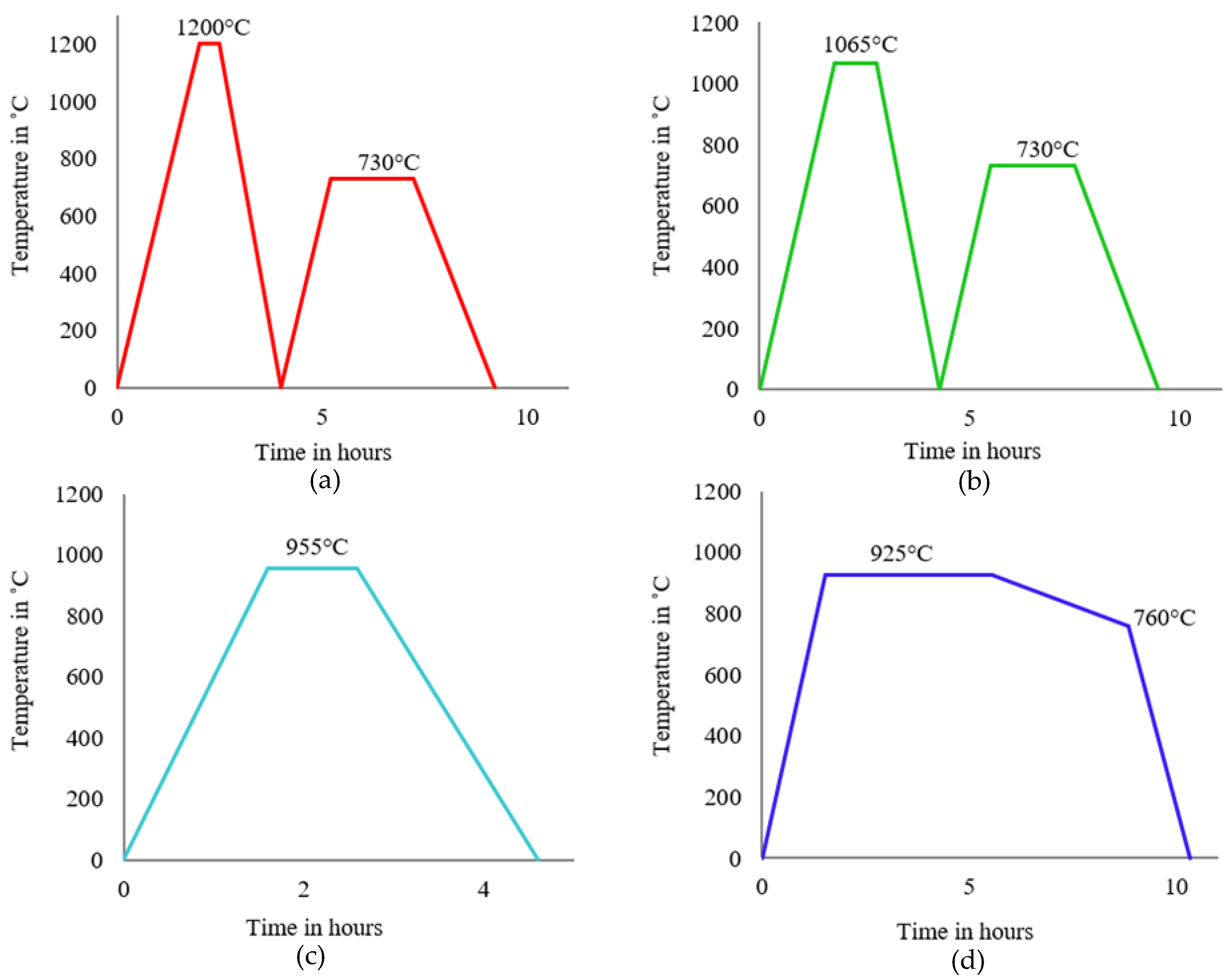
| β annealing + ageing treatment | 1200 °C/30 min, FC, 730 °C/2 h | 89.6 | 6.4 | 3.6 | 0.33 |
| 1065 °C/1 h, FC, 730 °C/2 h | 89.9 | 6.5 | 3.5 | 0.34 | |
| α + β annealing | 955 °C/1 h, FC | 89.9 | 6.3 | 3.6 | 0.35 |
| 925 °C/4 h, CFC@50 °C/h to 760 °C, FC | 90.3 | 6.0 | 3.6 | 0.33 | |
| Heat Treatment Description | Abbreviation (Treatment Temperature/Hold Time, Cooling Type, Ageing Temperature/Hold Time) | Impact Toughness (J) | |||||
|---|---|---|---|---|---|---|---|
| S1* | S2 | S3 | Mean | SD^ | SE+ | ||
| - | As-extruded (VS-E3’) | 13 | 14 | 14 | 13.67 | 0.58 | 0.33 |
| β annealing + ageing treatment | 1200 °C/30 min, FC, 730 °C/2 h | 16 | 16 | 15 | 15.67 | 0.58 | 0.33 |
| 1065 °C/1 h, FC, 730 °C/2 h | 17 | 14 | 15 | 15.33 | 1.53 | 0.88 | |
| α + β annealing | 955 °C/1 h, FC | 20 | 20 | 18 | 19.33 | 1.15 | 0.67 |
| 925 °C/4 h, CFC@50 °C/h to 760 °C, FC | 20 | 19 | 19 | 19.33 | 0.58 | 0.33 | |
| Starting Material | Heat Treatment Category | Microstructure | Impact Toughness (J) | Comment | Reference |
|---|---|---|---|---|---|
| PCE | β-annealed and aged | Lamellar or basketweave | 15.33–15.67 | O ~0.34 ± 0.005 wt.% | Current work |
| α + β-annealed | Lamellar | 19.33 | |||
| Quenched and aged | Martensitic or mixture of primary α, secondary α and β phase | 13.67 | [24] | ||
| TPM+ | As-processed | Lamellar, Widmanstätten | 9.7–14.3 | O < 0.32–0.43 wt.% | [25,26] |
| Ingot | - | - | 17 | O < 0.20 wt.% | [15] |
| Ingot | Mill-annealed | - | 20–27 | O < 0.20 wt.% | [10] |
| Ingot (ELI) | - | 20–40 | O < 0.13 wt.% | [10] | |
| HIPed investment cast | α + β-annealed plus ageing | - | 28.2–30.6 | O between 0.16–0.19 wt.% | [1,8] |
| Β-annealed plus ageing | - | 26–28.7 | |||
| As-casted | Quenching | Mixture of acicular αʹ, β structures and primary α | 5–10 | O ≤ 0.20 wt.% | [4,5] |
| Duplex | Widmanstätten | 8–12 | |||
| Rolled plate | α + β-annealed | Biomodal | 35 | O ≤ 0.186 wt.% | [7] |
| β-annealed | Lamellar | 24 | |||
| Rolled plate | α + β-annealed | Equiaxed | 13 | non-standard v-notch sample, O ≤ 0.20 wt.% | [12] |
| β-annealed | Coarse lamellar | 19 | |||
| Mill-annealed * | Quenched and aged | Martensitic microstructure or primary α phase plus quenched and aged | 16–28 | Impact Specimens with U notch *, Oxygen 0.18 wt.% | [6] |
| Annealed | Coarse-grained lamellar or Duplex microstructure | 42–46 | |||
| α + β-annealed + aged | Biomodal | 50 J/cm2 (40 J) | |||
| Annealing 735 °C for two hours | - | 10.1 | |||
| HIPed PREP* | Annealing 735 °C for two hours | - | 10.1 | U-notch * Charpy specimens, oxygen < 0.12 wt.% | [22] |
| Selective laser melted | Annealing 735 °C for two hours | - | 10.1 | - | [12] |
| Electron beam melting | HIPed | - | 3.78–57.73 | O between 0.11–0.46 wt.% | [27] |
© 2019 by the authors. Licensee MDPI, Basel, Switzerland. This article is an open access article distributed under the terms and conditions of the Creative Commons Attribution (CC BY) license (http://creativecommons.org/licenses/by/4.0/).
Share and Cite
Singh, A.P.; Yang, F.; Torrens, R.; Gabbitas, B. Heat Treatment, Impact Properties, and Fracture Behaviour of Ti-6Al-4V Alloy Produced by Powder Compact Extrusion. Materials 2019, 12, 3824. https://doi.org/10.3390/ma12233824
Singh AP, Yang F, Torrens R, Gabbitas B. Heat Treatment, Impact Properties, and Fracture Behaviour of Ti-6Al-4V Alloy Produced by Powder Compact Extrusion. Materials. 2019; 12(23):3824. https://doi.org/10.3390/ma12233824
Chicago/Turabian StyleSingh, Ajit Pal, Fei Yang, Rob Torrens, and Brian Gabbitas. 2019. "Heat Treatment, Impact Properties, and Fracture Behaviour of Ti-6Al-4V Alloy Produced by Powder Compact Extrusion" Materials 12, no. 23: 3824. https://doi.org/10.3390/ma12233824
APA StyleSingh, A. P., Yang, F., Torrens, R., & Gabbitas, B. (2019). Heat Treatment, Impact Properties, and Fracture Behaviour of Ti-6Al-4V Alloy Produced by Powder Compact Extrusion. Materials, 12(23), 3824. https://doi.org/10.3390/ma12233824