Measurements of Forces and Selected Surface Layer Properties of AW-7075 Aluminum Alloy Used in the Aviation Industry after Abrasive Machining


Abstract
1. Introduction
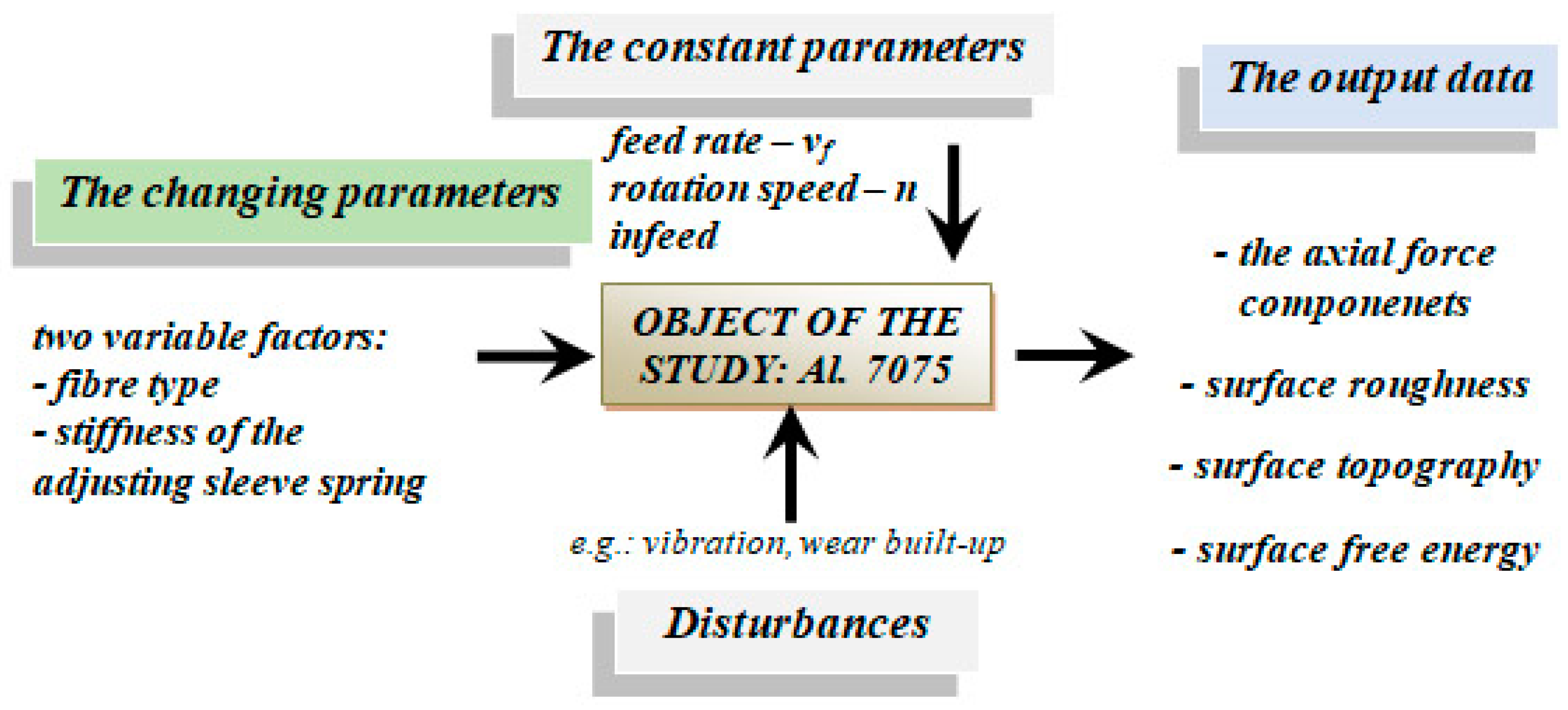
2. Materials and Methods
2.1. Material
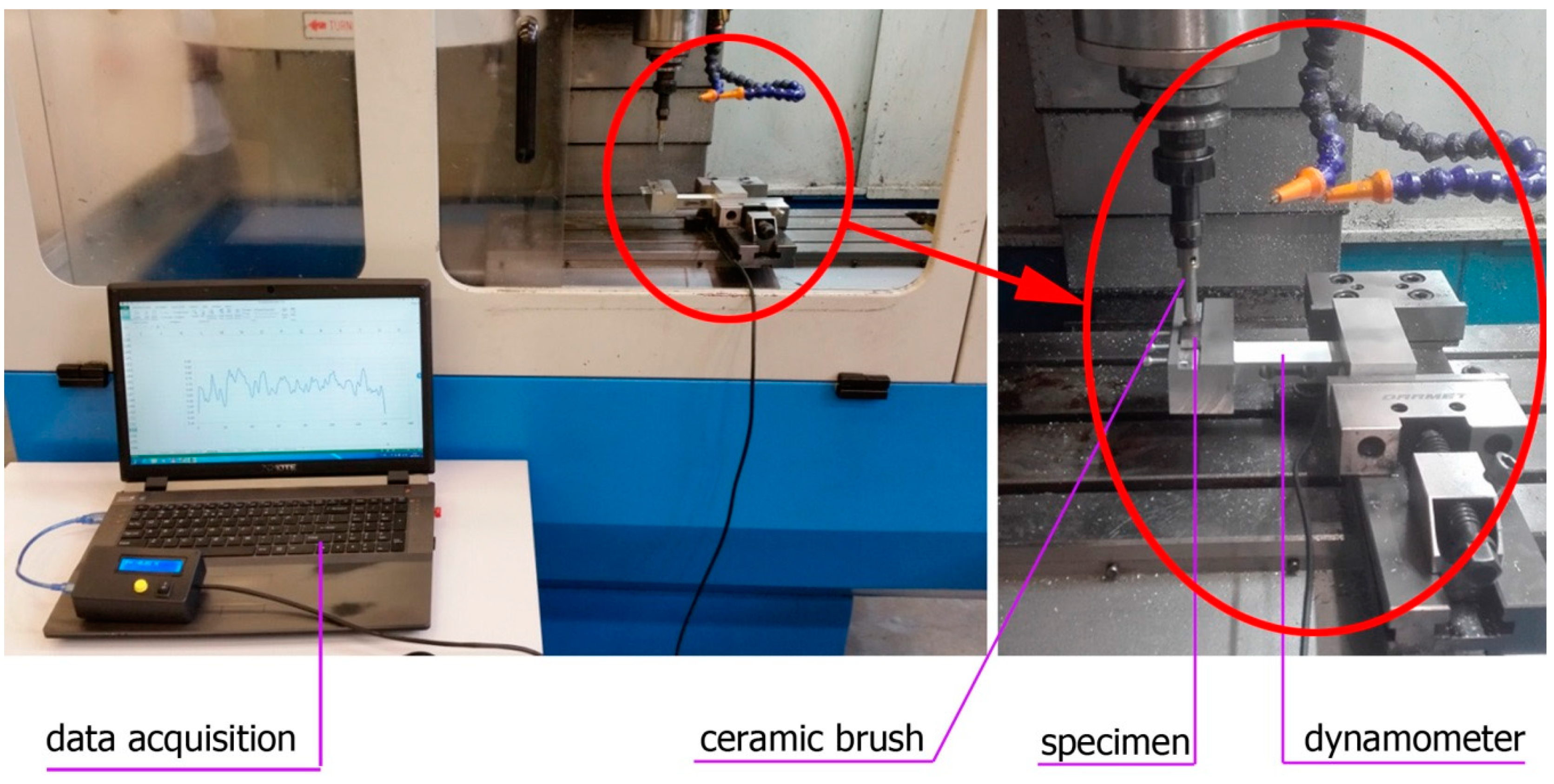
2.2. Test Setup
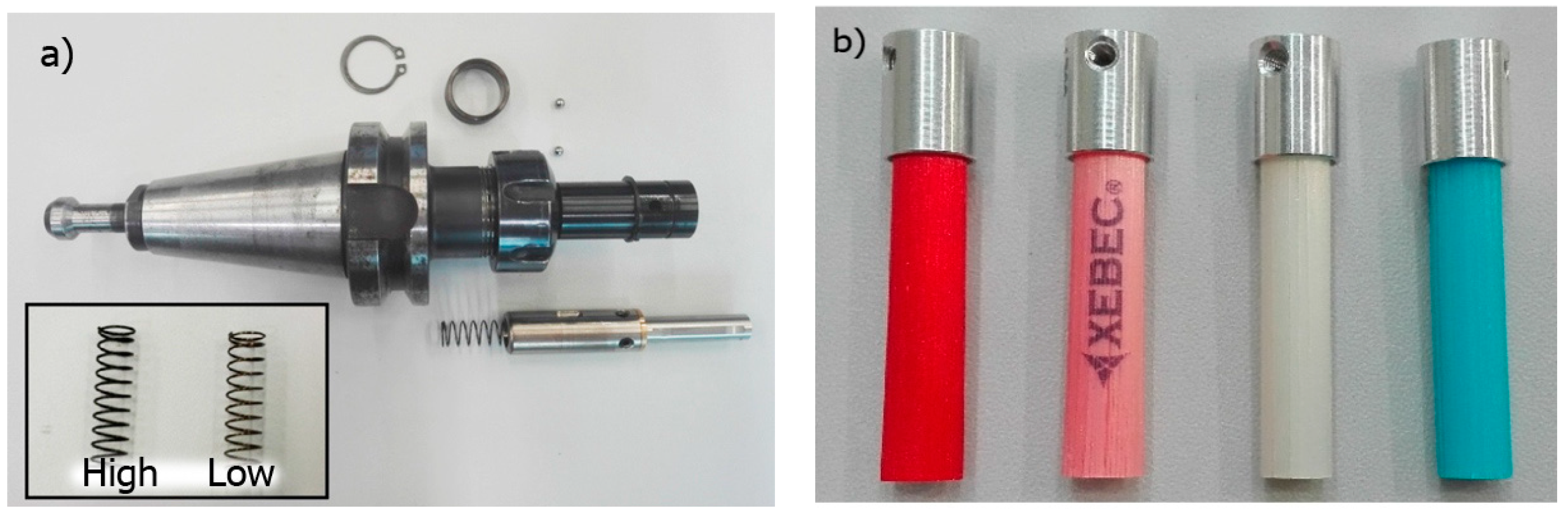
2.3. Tools
- Pink – highly flexible, low impact on surfaces;
- Red – flexible, deburring soft materials;
- White – rigid, high efficiency, deburring, reducing surface roughness;
- Blue – extremely rigid, high efficiency in machining difficult-to-cut materials.
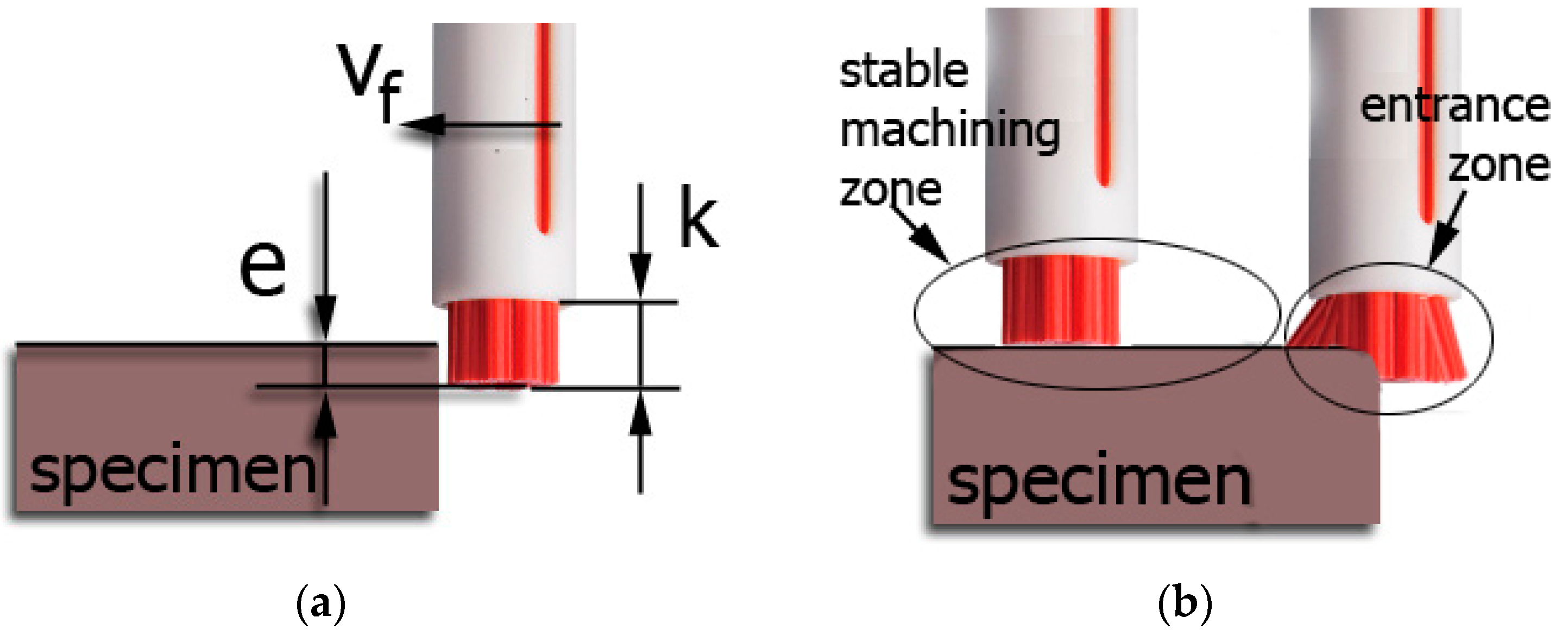
2.4. Brushing Conditions
2.5. Measurements Methodology
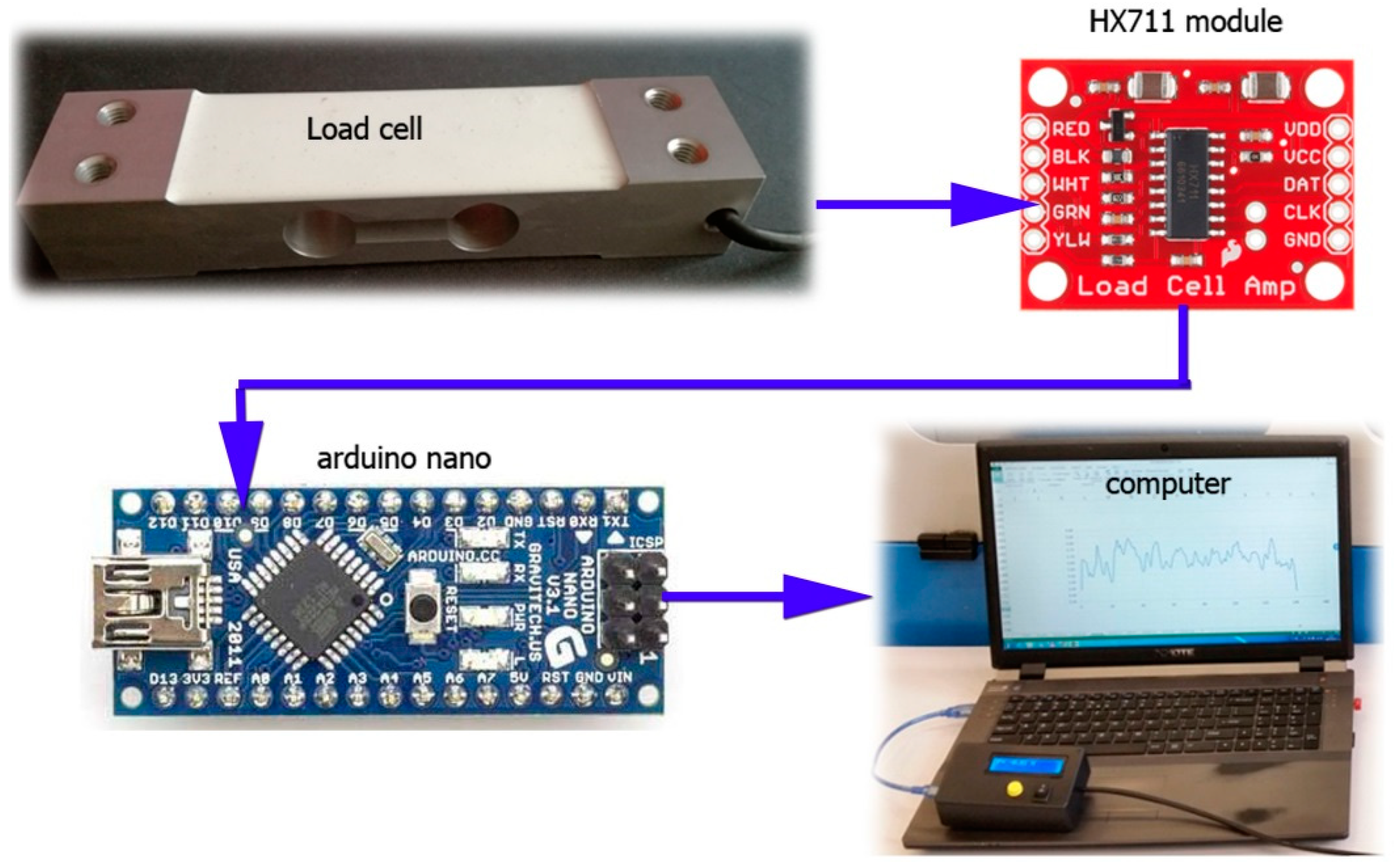
2.5.1. Force Measurement Sensor
2.5.2. Surface Roughness Measurements
2.5.3. Texture Measurements
2.5.4. Surface Free Energy Measurements
3. Results
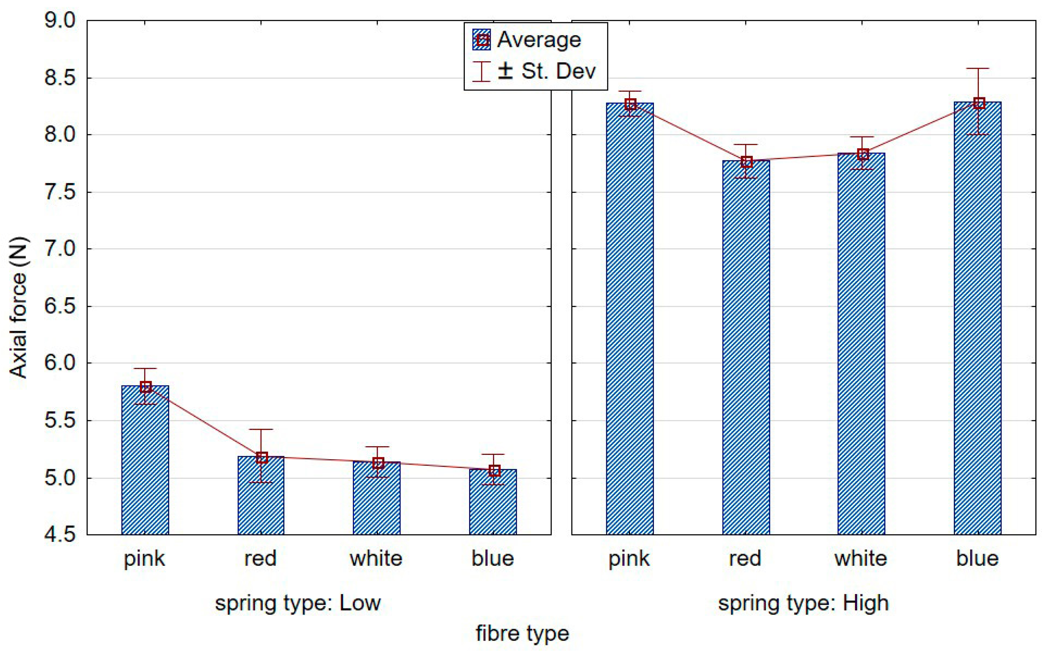
3.1. Axial Force
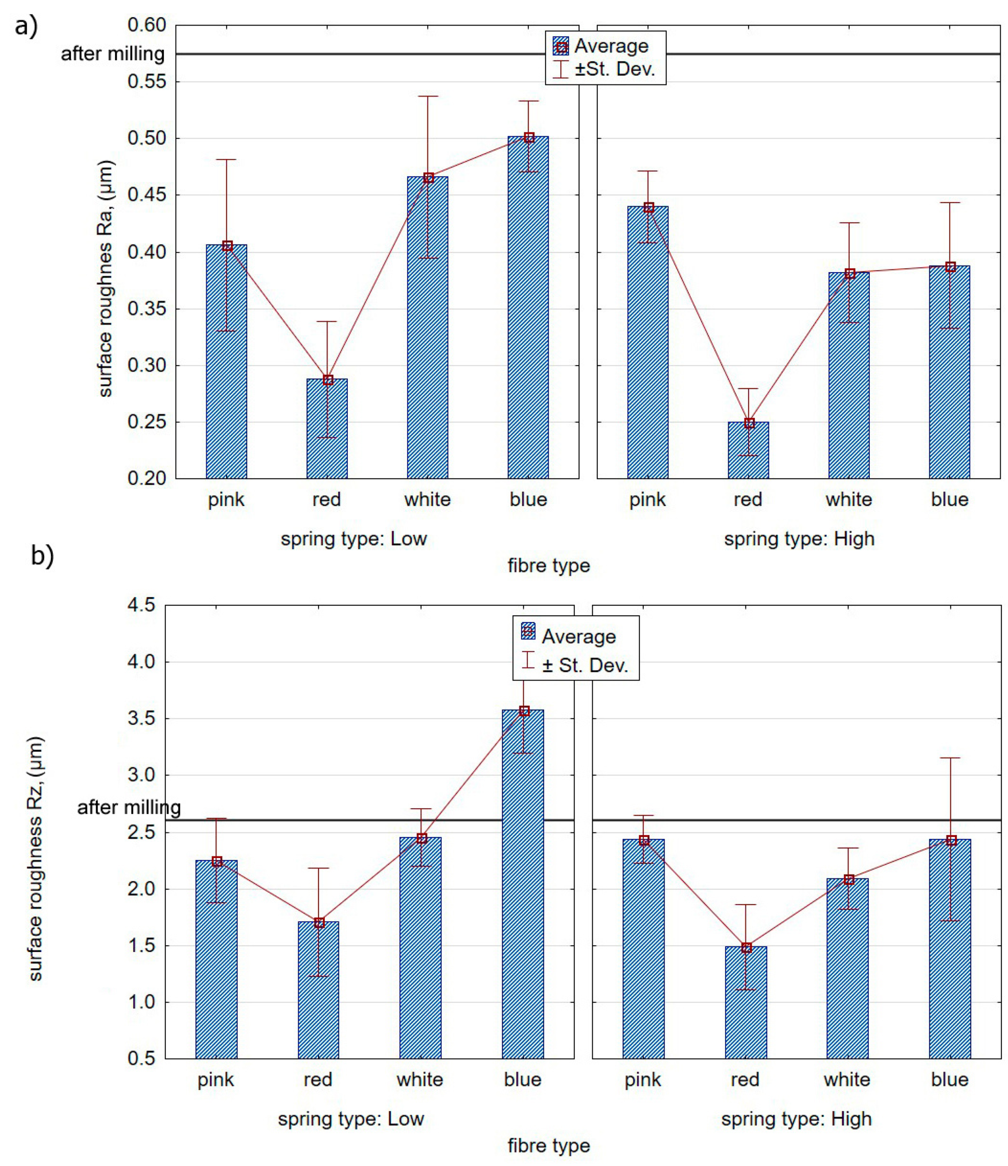
3.2. Surface Roughness
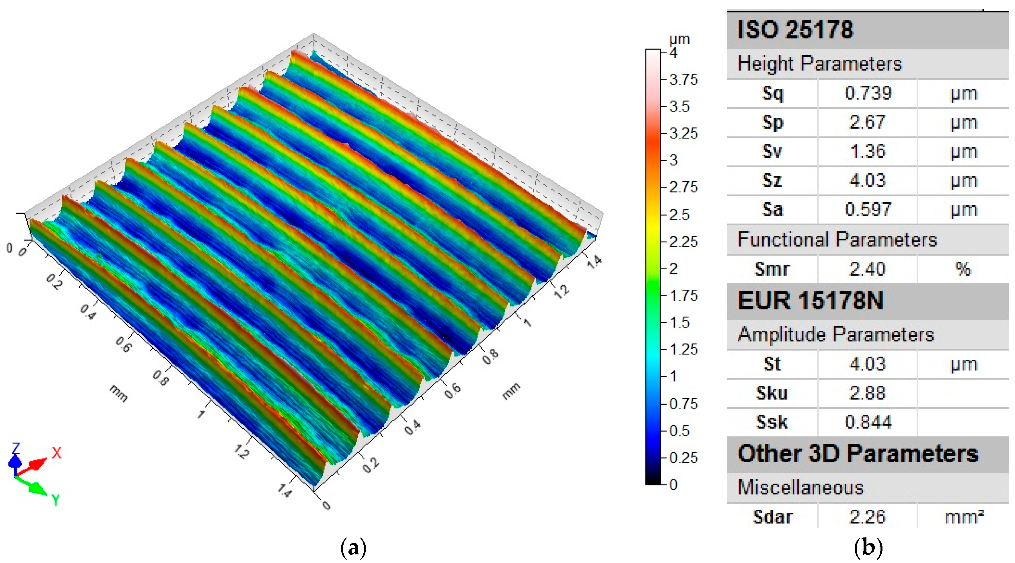
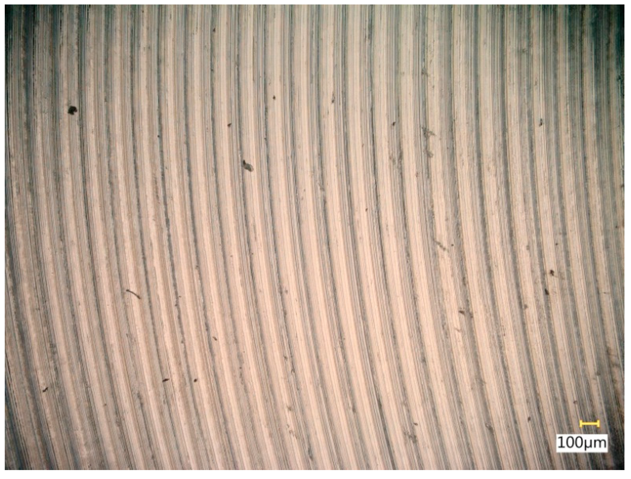
3.3. Surface Topography
3.4. Surface Texture
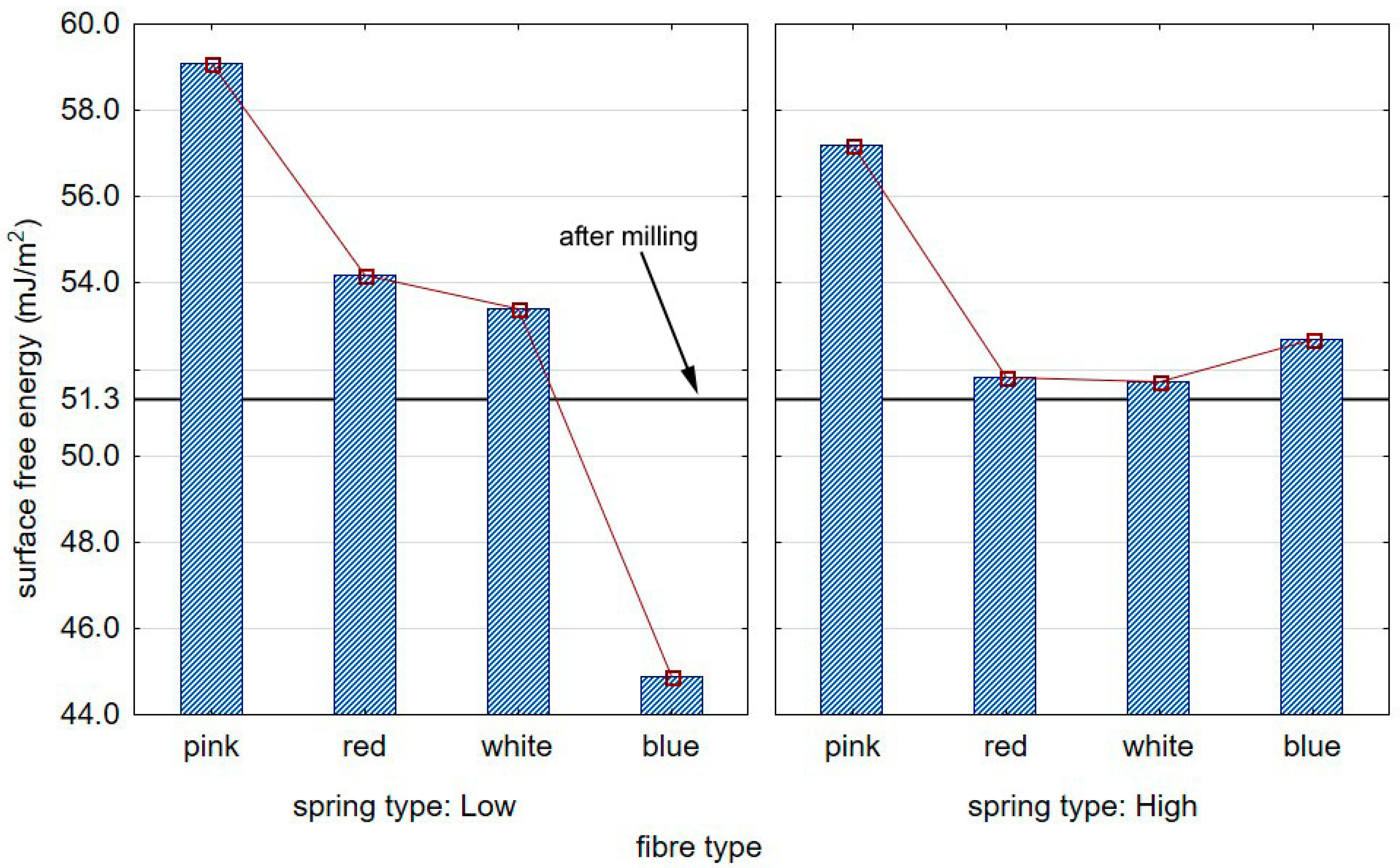
3.5. Surface Free Energy
4. Discussion
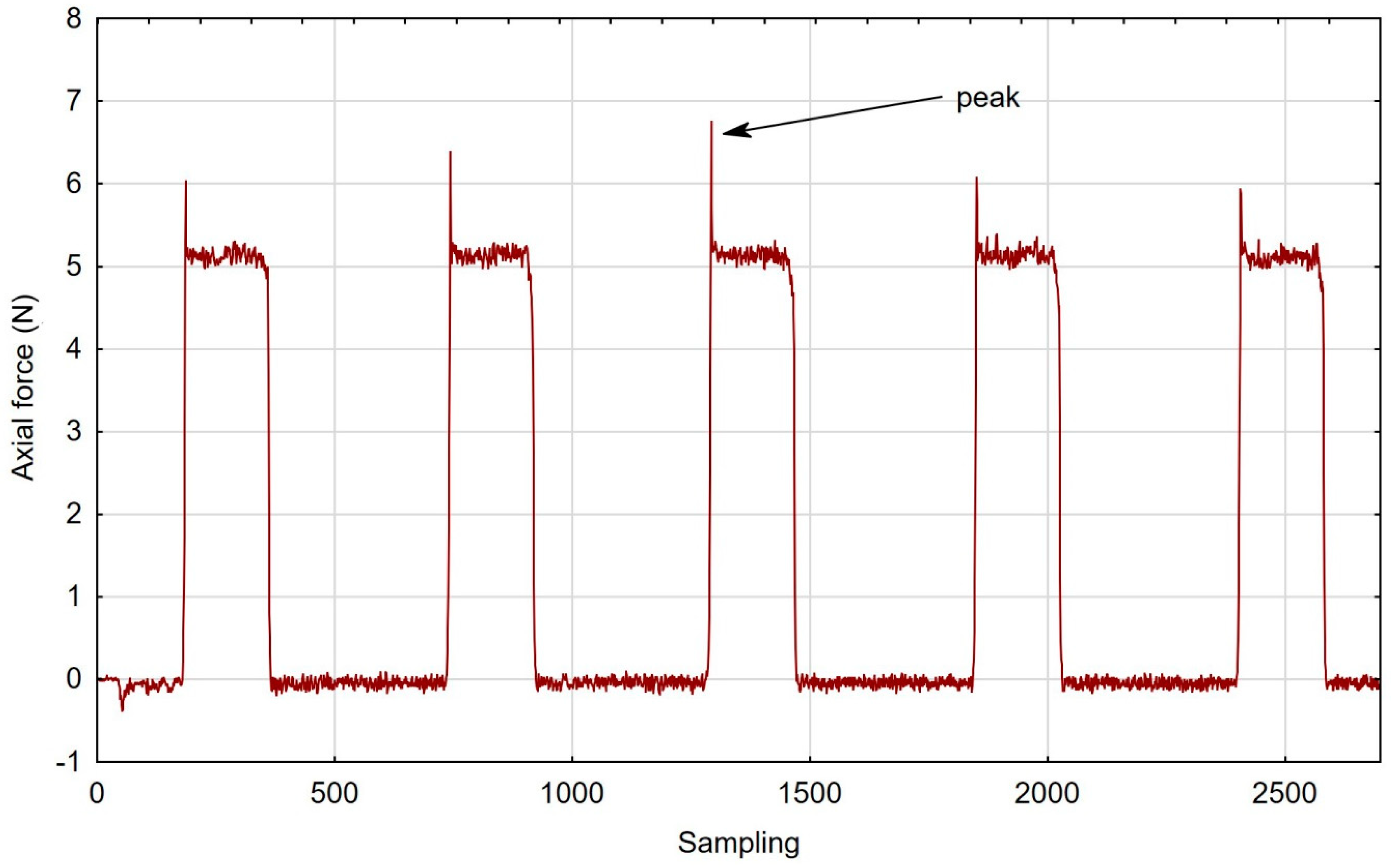
- Machining with high-stiffness fibres led to peaks in the axial force applied by the brush entering into the cut (not observed in the case of the most flexible brush—pink); the peaks might indicate the unsuitability of stiff-fibre brushes for thin-walled flexible substrate applications;
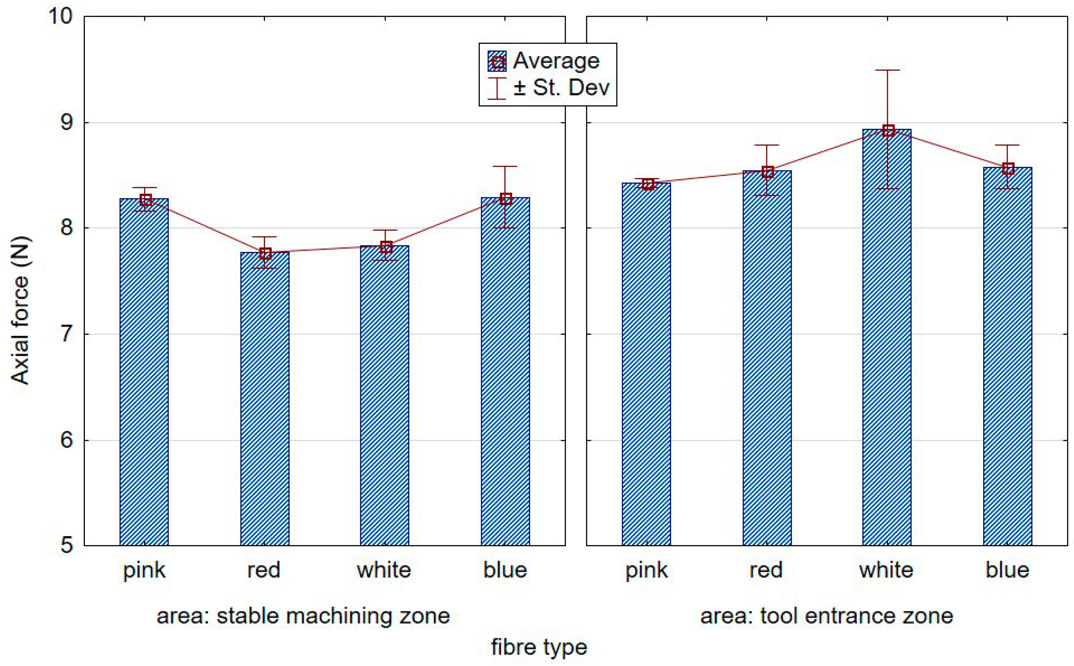
- When machining with the low-stiffness spring in the adjustment sleeve, the axial forces were substantially lower with increasing fibre stiffness;
- Brush stiffness affected the axial force in brushing with the high-stiffness spring only to a small degree;
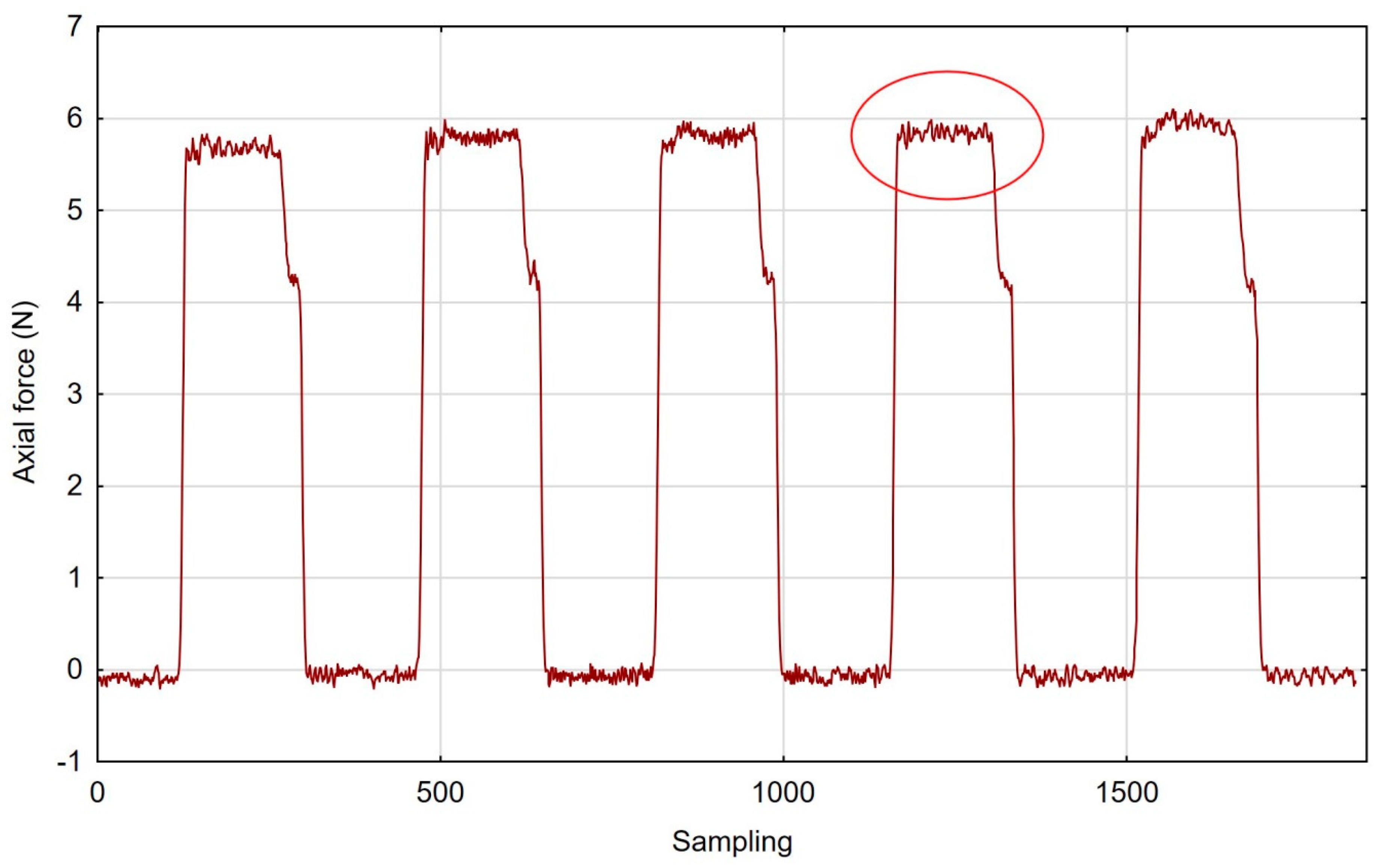
- The tool entry into the cut showed higher standard deviations owing to the highly dynamic character of the process;
- The lowest surface roughness values were obtained after brush treatment with red fibres, for both “low” and “high” spring stiffness settings.
- The use of rigid fibres (i.e., blue and white) may lead to carving micro-grooves on treated surfaces, which results in an increase in the surface roughness parameters (particularly Sz);
- The use of “pink” brushes and “low” spring stiffness settings in the adjustment sleeve resulted in a significant increase in the value of the surface free energy by approximately 15% compared to the samples prior to brushing. This is of paramount importance, particularly in the aviation industry where adhesion technologies—highly sensitive to improper bonding—are employed in adhesive joint assemblies and in various types of protective or decorative coatings;
- The effect of the spring type on axial force was higher than that of the brush fibre stiffness. Nevertheless, it is more relevant for other effects of treatment (surface finish/roughness, the effectiveness of deburring, etc.)
Author Contributions
Funding
Conflicts of Interest
References
- Królczyk, G.; Legutko, S. Investigations into Surface Integrity in the Turning Process of Duplex Stainless Steel. Trans. FAMENA 2014, 38, 77–82. [Google Scholar]
- Królczyk, G.; Legutko, S.; Nieslony, P.; Gajek, M. Study of the surface integrity microhardness of austenitic stainless steel after turning. Teh. Vjesn. Tech. Gaz. 2014, 21, 1307–1311. [Google Scholar]
- Kuczmaszewski, J.; Zaleski, K.; Matuszak, J.; Mądry, J. Testing Geometric Precision and Surface Roughness of Titanium Alloy Thin-Walled Elements Processed with Milling. In Advances in Manufacturing II. MANUFACTURING 2019; Springer: Cham, Switzerland, 2019. [Google Scholar]
- Aurich, J.C.; Dornfeld, D.; Arrazola, P.J.; Franke, V.; Leitz, L.; Min, S. Burrs—Analysis, control and removal. Cirp Ann. Manuf. Technol. 2009, 58, 519–542. [Google Scholar] [CrossRef]
- Matuszak, J.; Zaleski, K. Analysis of deburring effectiveness and surface layer properties around edges of workpieces made of 7075 aluminium alloy. Aircr. Eng. Aerosp. Technol. 2018, 90, 515–523. [Google Scholar] [CrossRef]
- Stango, R.J. Filamentary brushing tools for surface finishing applications. Met. Finish. 2002, 100, 86–95. [Google Scholar] [CrossRef]
- Matuszak, J.; Zaleski, K. Effect of brushing parameters upon edge states after wire brushing of AZ91 HP magnesium alloy. Adv. Sci. Technol. Res. J. 2013, 7, 55–60. [Google Scholar] [CrossRef]
- Rodríguez, A.; Fernández, A.; López de Lacalle, L.; Sastoque Pinilla, L. Flexible abrasive tools for the deburring and finishing of holes in superalloys. J. Manuf. Mater. Process. 2018, 2, 82. [Google Scholar] [CrossRef]
- Novotný, F.; Horák, M.; Starý, M. Abrasive cylindrical brush behaviour in surface processing. Int. J. Mach. Tools Manuf. 2017, 118, 61–72. [Google Scholar] [CrossRef]
- Rodríguez, A.; de Lacalle, L.N.L.; Fernández, A.; Braun, S. Elimination of surface spiral pattern on brake discs. J. Zhejiang Univ. Sci. A 2014, 15, 53–60. [Google Scholar] [CrossRef]
- Kitahara, H.; Yada, T.; Tsushida, M.; Ando, S. Microstructure and Evaluation of Wire-brushed Mg Sheets. Procedia Eng. 2011, 10, 2737–2742. [Google Scholar] [CrossRef]
- Kitahara, H.; Yada, T.; Hashiguchi, F.; Tsushida, M.; Ando, S. Mg alloy sheets with a nanocrystalline surface layer fabricated by wire-brushing. Surf. Coat. Technol. 2014, 243, 28–33. [Google Scholar] [CrossRef]
- Matuszak, J.; Kłonica, M.; Zagórski, I. Effect of Brushing Conditions on Axial Forces in Ceramic Brush Surface Treatment. In Proceedings of the 2019 IEEE International Workshop on Metrology for Aerospace, Turin, Italy, 19–21 June 2019. [Google Scholar]
- Kuczmaszewski, J.; Login, W.; Piesko, P.; Zawada-Michalowska, M. Assessment of the accuracy of high-speed machining of thin-walled EN AW-2024 aluminium alloy elements using carbide milling cutter and with PCD blades. In Advances in Manufacturing, Lecture Notes in Mechanical Engineering; Springer: Cham, Germany, 2018; pp. 671–680. [Google Scholar]
- Del Sol, I.; Rivero, A.; López de Lacalle, L.N.; Gamez, A.J. Thin-Wall Machining of Light Alloys: A Review of Models and Industrial Approaches. Materials 2019, 12, 2012. [Google Scholar] [CrossRef] [PubMed]
- González, H.; Calleja, A.; Pereira, O.; Ortega, N.; Lopez de Lacalle, L.N.; Barton, M. Super abrasive machining of integral rotary components using grinding flank tools. Metals 2018, 8, 24. [Google Scholar] [CrossRef]
- Campa, F.J.; López de Lacalle, L.N.; Urbicain, G.; Lamikiz, A.; Seguy, S.; Arnaud, L. Critical thickness and dynamic stiffness for chatter avoidance in thin floors milling. Adv. Mater. Res. 2011, 188, 116–121. [Google Scholar] [CrossRef]
- Zagórski, I.; Kulisz, M.; Semeniuk, A. Artificial neural network modelling of cutting force components in milling. ITM Web. Conf. 2017, 15, 02001. [Google Scholar] [CrossRef]
- Józwik, J.; Mika, D.; Dziedzic, K. Vibration of thin walls during cutting process of 7075 T651 aluminium alloy. Manuf. Technol. 2016, 16, 113–120. [Google Scholar]
- Zagorski, I.; Kulisz, M.; Semeniuk, A.; Malec, A. Artificial neural network modelling of vibration in the milling of AZ91D alloy. Adv. Sci. Technol. Res. J. 2017, 11, 261–269. [Google Scholar] [CrossRef]
- Rusinek, R.; Zaleski, K. Dynamics of thin-walled element milling expressed by recurrence analysis. Meccanica 2015, 51, 1275–1286. [Google Scholar] [CrossRef]
- Danis, I.; Monies, F.; Lagarrigue, P.; Wojtowicz, N. Cutting forces and their modelling in plunge milling of magnesium-rare earth alloys. Int. J. Adv. Manuf. Technol. 2016, 84, 1801–1820. [Google Scholar] [CrossRef]
- Kim, Y.; Kim, J.; Lee, S.K. Investigation of surface uniformity machined by ceramic brush. Int. J. Adv. Manuf. Technol. 2018, 94, 2593–2603. [Google Scholar] [CrossRef]
- Monies, F.; Danis, I.; Lagarrigue, P.; Gilles, P.; Rubio, W. Balancing of the transversal cutting force for pocket milling cutters: Application for roughing a magnesium-rare earth alloy. Int. J. Adv. Manuf. Technol. 2016, 89, 45–64. [Google Scholar] [CrossRef]
- Monies, F.; Danis, I.; Bes, C.; Cafieri, S.; Mongeau, M. A new machining strategy for roughing deep pockets of magnesium-rare earth alloys. Int. J. Adv. Manuf. Technol. 2017, 92, 3883–3901. [Google Scholar] [CrossRef]
- Akyüz, B. Comparison of the machinability and wear properties of magnesium alloys. Int. J. Adv. Manuf. Technol. 2014, 75, 1735–1742. [Google Scholar] [CrossRef]
- Zgórniak, P.; Stachurski, P.; Ostrowski, D. Application of thermographic measurements for the determination of the impact of selected cutting parameters on the temperature in the workpiece during milling process. Stroj. Vestn. J. Mech. Eng. 2016, 62, 657–664. [Google Scholar] [CrossRef][Green Version]
- Kwiatkowski, M.P.; Kłonica, M.; Kuczmaszewski, J.; Satoch, S. Comparative analysis of energetic properties of Ti6Al4V titanium and EN-AW-2017A(PA6) aluminum alloy surface layers for an adhesive bonding application. Ozone Sci. Eng. J. Int. Ozone Assoc. 2013, 35, 220–228. [Google Scholar] [CrossRef]
- Kłonica, M. Impact of thermal fatigue on Young’s modulus of epoxy adhesives. Adv. Sci. Technol. Res. J. 2015, 9, 103–106. [Google Scholar] [CrossRef][Green Version]
- Kłonica, M.; Kuczmaszewski, J.; Samborski, S. Effect of a notch on impact resistance of the Epidian 57/Z1 epoxy material after “Thermal Shock”. Solid State Phenom. 2016, 240, 161–167. [Google Scholar] [CrossRef]
- Kubit, A.; Trzepiecinski, T.; Kłonica, M.; Hebda, M.; Pytel, M. The influence of temperature gradient thermal shock cycles on the interlaminar shear strength of fibre metal laminate composite determined by the short beam test. Compos. Part B Eng. 2019, 176, 107217. [Google Scholar] [CrossRef]


| Chemical Composition, wt. % | Physical Properties | Specimen | ||
|---|---|---|---|---|
| Cu | 1.59 | Rm MPa | 559 |  |
| Mn | 0.01 | |||
| Mg | 2.56 | |||
| Cr | 0.18 | Rp0.2 MPa | 448 | |
| Zn | 5.78 | |||
| Si | 0.07 | |||
| Fe | 0.13 | HB | 172 | |
| Ti | 0.05 | |||
| Al | Rest | |||
| Tool Data | |||
| Brush Tool | Fibre | Stiffness of Offset Adjustment Sleeve Spring | Fibre Projection Length from Sleeve “k” (mm) |
| ceramic brush | pink | high | 5.5 |
| low | |||
| red | high | ||
| low | |||
| white | high | ||
| low | |||
| blue | high | ||
| low | |||
| Cutting Data | |||
| Medium | Brush Speed (rev/min) | Feed Rate (mm/min) | Infeed “e” (mm) |
| Dry machining | 5000 | 1000 | 0.5 |
| Pink | Red |
| Sa = 0.415 µm, Sz = 3.99 µm | Sa = 0.272 µm, Sz = 4.79 µm |
 |  |
| White | Blue |
| Sa = 0.394 µm, Sz = 5.69 µm | Sa = 0.336 µm, Sz = 4.57 µm |
 |  |
| Pink | Red |
| Sa = 0.359 µm, Sz = 5.71 µm | Sa = 0.351 µm, Sz = 5.74 µm |
 |  |
| White | Blue |
| Sa = 0.338 µm, Sz = 7.08 µm | Sa = 0.312 µm, Sz = 5.73 µm |
 |  |
| Pink | Red |
 |  |
| White | Blue |
 |  |
| Pink | Red |
 |  |
| White | Blue |
 |  |
© 2019 by the authors. Licensee MDPI, Basel, Switzerland. This article is an open access article distributed under the terms and conditions of the Creative Commons Attribution (CC BY) license (http://creativecommons.org/licenses/by/4.0/).
Share and Cite
Matuszak, J.; Kłonica, M.; Zagórski, I. Measurements of Forces and Selected Surface Layer Properties of AW-7075 Aluminum Alloy Used in the Aviation Industry after Abrasive Machining. Materials 2019, 12, 3707. https://doi.org/10.3390/ma12223707
Matuszak J, Kłonica M, Zagórski I. Measurements of Forces and Selected Surface Layer Properties of AW-7075 Aluminum Alloy Used in the Aviation Industry after Abrasive Machining. Materials. 2019; 12(22):3707. https://doi.org/10.3390/ma12223707
Chicago/Turabian StyleMatuszak, Jakub, Mariusz Kłonica, and Ireneusz Zagórski. 2019. "Measurements of Forces and Selected Surface Layer Properties of AW-7075 Aluminum Alloy Used in the Aviation Industry after Abrasive Machining" Materials 12, no. 22: 3707. https://doi.org/10.3390/ma12223707
APA StyleMatuszak, J., Kłonica, M., & Zagórski, I. (2019). Measurements of Forces and Selected Surface Layer Properties of AW-7075 Aluminum Alloy Used in the Aviation Industry after Abrasive Machining. Materials, 12(22), 3707. https://doi.org/10.3390/ma12223707