Abstract
The purpose of the research was to assess the possibility of using granulated expanded glass aggregate (GEGA) with cement grout as a replacement of a sub-grade and frost-protection layer, made of natural fine aggregates (NATU), stabilized with a hydraulic binder. Instead of traditional parts of the road construction, such as the sub-grade and frost-protection layer with the application of fine aggregate, stabilized with cement, the authors propose only one layer, made of lightweight water-permeable material, containing GEGA with a grain size from 8 to 11.2 mm. In the article the authors present the physical properties of the materials, applied for the road layers, the properties of the fine aggregate, stabilized with cement, and those of the cement composite with GEGA as an alternative solution. The laboratory test results of fine aggregates, stabilized with cement and of cement composites with GEGA, are presented. Porosity, volume density, compressive strength, and frost resistance are being researched. The results of those tests are meant to play an essential role in designing the thickness of road layers. Different types of pavement structure (asphalt and concrete) and different values of road load are being considered in the given work. The paper is concluded with considerations on an innovative solution, involving the use of ecological materials.
1. Introduction
The road construction sector all around the world is the largest consumer of natural aggregates [1]. It is reported that global annual use of the aggregates constitutes over 40 billion tons, 90% of which is produced on the basis of natural resources. The rest are aggregates, made of the recycled materials (about 5%), synthetic aggregates (2%) and aggregates, extracted from the sea area (about 2%) [2]. Despite the presence of a number of areas, rich in natural aggregate sources, certain countries are characterized by a deficit of natural aggregates. It is often the case that a fine aggregate is inapplicable in construction because of too small a grain size.
The use of industrial by-products in road construction can contribute to the discussion on reducing the consumption of natural resources and reducing the areas of landfills. Glass waste could be considered as a potential alternative secondary raw material in road construction [3,4,5,6]. Waste glass is an excellent material to be subjected to repeated recycling [7,8]. At the same time, due to its composition and structure, glass does not pose any hazard to the environment as a recycled material. It is estimated that annually, in Europe, 11–40 kg of glass waste is generated per capita, depending on the country. Overall production of waste is constantly growing. Glass constitutes approximately 10%–15% of municipal waste, depending on the waste management practices in the country.
According to the World Bank, annual waste production is about 2 billion tons [9,10,11,12]. The development of waste glass processing technology allows reaching up to 100% recycling, which contributes to the reduction of energy consumption for processing primary raw materials for the production of glass, i.e., sand, soda, and limestone dust [13,14]. There are many concerns about the industrial use of the recycled products. With this in mind, many studies are being carried out, confirming the possibility of using waste materials, including glass cullet [15]. Expanded glass aggregate, where cullet is the key component, is proposed to be applied for the improvement of the road sub-grade. The possibility of using shredded waste glass in road engineering, as a substitute for coarse aggregate, was carried out by [16,17,18,19]. Another solution was the use of shredded glass instead of natural sand. Such studies were conducted by [20,21,22,23]. Another lightweight aggregate, which has already been used in road construction, is produced from expanded clay or fly ash, coming from coal combustion or municipal waste incineration plants. It has been well-known and successfully used for quite a long time [24,25,26,27,28,29]. The examples of application of lightweight aggregate fillers, presented in the publications, confirm that this solution is technically feasible in the road construction industry, and its significant advantages influence the possibility of reducing costs of road construction as compared to traditional materials [30,31,32,33,34,35,36,37,38,39]. Therefore, the authors have made an attempt to use GEGA as a substitute for the natural aggregate in the sub-grade and the frost protection layer of the road foundation. The main assumption, which is made here, is that construction material should meet all the requirements, related to, among others, mechanical properties, durability, and economic coefficient [40,41].
The authors put forward the thesis that it is possible to use GEGA of diameter 8/11.2 mm with cement grout, instead of two layers: a sub-grade and a frost-protection layer of the road. At the same time, special attention has been paid to the quality and the cost of the recycled materials. The main assumption was that the quality, cost, and durability of the new solution cannot turn out less beneficial for the interested parties than the solution, traditionally used in road construction. The main profit of the new solution implementation can be seen in lower consumption of natural resources, application of waste glass and, therefore, a reduction of CO2 emission.
On the basis of the research, carried out by [42,43], the authors assessed the suitability of the glass waste in the form of foam glass as an alternative to natural sand, used as a sub-grade and a frost-protection layer of the pavement road.
The authors of the article below undertook a research into the possibilities of using GEGA from the waste glass in road construction. The main goal of the research was to find a new solution that would allow reducing the consumption of natural resources and, instead, to use the material derived from glass waste recycling.
2. Materials and Methods
2.1. Assumptions of Pavement Structure and Adopted Materials
Two main types of pavement structure were analyzed: type 1—flexible pavement with asphalt mixture layers and base course, made of an unbound mixture, and type 2—rigid pavement with a concrete slab in a wearing course layer and base course layer, made of a mixture, bound with a hydraulic binder. Traffic categories were marked in accordance with the guidelines for the road pavement design in Poland [44]. For flexible pavements, road structures for heavy traffic (22.00–52.00 million equivalent standard axle load (ESAL) of 100 kN/lane), for medium traffic (2.50–7.30 million of ESAL of 100 kN/lane) and for light traffic (0.09–0.50 million of ESAL of 100 kN/lane) were assumed. Additionally, there were subsurface and groundwater conditions for cohesive soils adopted, e.g., sandy clay, and high groundwater level. In the analyzed examples, the proposed new solution, which was assumed, was frost protection layer performing the function of a drainage layer at the same time. For rigid pavements, road structures for heavy traffic (42.63–101.25 million of ESAL of 100 kN/lane), for medium traffic (6.39–15.99 million of ESAL of 100 kN/lane), and for light traffic (0.15–0.75 million of ESAL of 100 kN/lane) were assumed. Additionally, subsurface and groundwater conditions, as well as conditions for the application of a drainage layer, were assumed analogously as for flexible pavements. The layout of type 1 and 2 pavement layers is schematically shown in Figure 1.
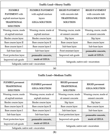
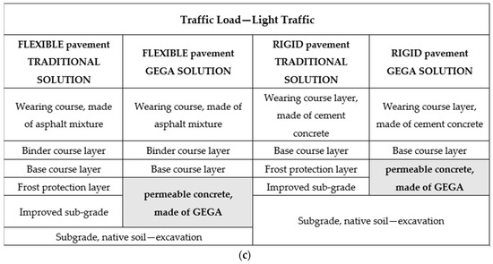
Figure 1.
Structure of road layers design for flexible and rigid pavements—traditional and with the use of permeable concrete, made of GEGA for traffic load: (a) heavy traffic, (b) medium traffic, and (c) light traffic.
The new solution assumes the substitution of the traditional solution with one, single layer, made of permeable lightweight GEGA concrete, constituting, at the same time, a frost protection course and improved soil sub-grade. The characteristic feature of the permeable lightweight GEGA concrete is liquid permeability. Porous lightweight GEGA concrete is freeze and thaw resistant. Permeable concretes can be made of a single- or double- fraction aggregate with a grain size of more than 4 mm. The amount of cement paste shall be used in the quantity, allowing to cover individual grains of the aggregate and to create an interfacial transition zone (ITZ) between the grains of the aggregate.
Figure 1 shows structural layers of flexible and rigid pavements, made of traditional and permeable concrete, and the ones, made of permeable concrete with solutions using GEGA for traffic load: heavy, medium, and light traffic.
Apparent, the density of condensed fine aggregate, stabilized with cement, ranges up to 1700–2000 kg/m3 whereas, in the case of using artificial aggregates with the addition of fly ash or clay, the apparent density reaches only 1400 kg/m3. If we use GEGA, the apparent density does not exceed 1000 kg/m3. The size of the spaces between the grains can be controlled to some extent by the grain size of the coarse aggregate. The amount and the size of the spaces between the grains depends on the diameter of the aggregate and on the amount of cement grout surrounding the grains of the aggregate and partially filling the pores. The greater the void content of the aggregate composition is, and the less pore filling is, the larger the porosity and the higher the water permeability are. Additionally, the amount of slurry or mortar will influence the quality of ITZ between the grains of the aggregate and cement grout. With the increase of the amount of slurry and mortar, mechanical properties of the composite will be more beneficial. The overall porosity of the composite and, therefore, permeability change with the thickness of the ITZ. The higher the amount of slurry is, the thicker the contact zone is and, at the same time, the higher compression strength is.
2.2. Materials
Portland cement CEM II/A-V 42.5 N with 20% fly ash, according to EN 197-1, was used to perform the tests. Chemical content and physical properties of the cement CEM II/A-V 42.5 N are shown in Table 1. The tests have been carried out in the laboratory of Gdańsk University of Technology.

Table 1.
Chemical content and physical properties of the cement CEM II/A-V 42.5 N.
The main component of cement is CaO, and its content is 54%, while the content of SiO2 silica is approximately 25%. Natural fine aggregate with a grain size from 0 to 4 mm (NATU), meeting the requirements of EN 12620: 2010, was used for the test. Distribution curves of NATU are shown in Figure 2. The chemical composition of NATU is shown in Table 2 and Table 3. Figure 3 presents microscopic images of fine aggregate grains in the vicinity of cement paste.
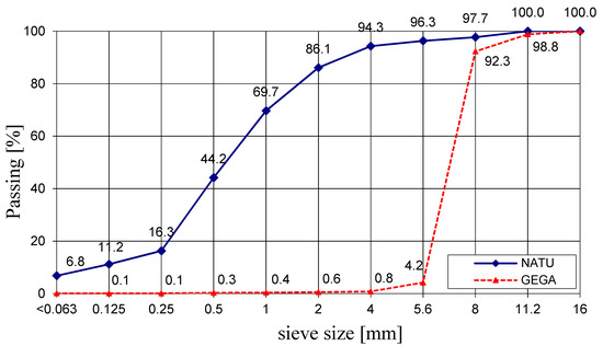
Figure 2.
Distribution curves of aggregates size.
Table 2.
Chemical composition of the aggregate.
Table 3.
Physical properties of the aggregates.
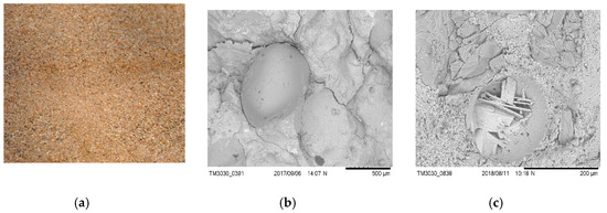
Figure 3.
Aggregate NATU (a) grains to 4 mm; (b) grain surface, 100×; (c) grain structure after cutting the sample (grain in the vicinity of cement paste), 1000×.
Artificial aggregate (GEGA) is manufactured from clear construction glass recycling and municipal waste recycling. The resources for clear glass production are quartz sand and additives, such as: sodium and calcium carbonate, flux: boron and lead oxide. Glass waste is ground in a ball mill and, next, cement is added, as well as fly ash, zeolite, metakaolin, foaming substances, and water. Then, out of the mix the granules are formed and placed in the furnace at 900 °C. Finally, a light-gray or beige porous granulated product is obtained. Granulated aggregate is sorted according to grain diameter. For this research GEGA (Figure 4) with a grain size ranging from 8 to 11.2 mm was applied. Its chemical and physical properties are shown in Table 2 and Table 3.
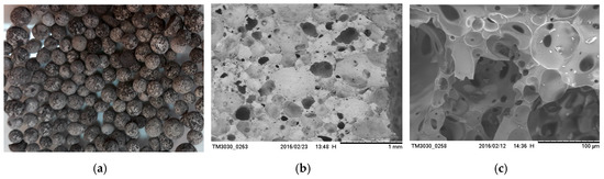
Figure 4.
Granulated expanded glass aggregate GEGA (a); grains at 11.2 mm; (b) structure of GEGA, 200×; (c) structure of GEGA, 1000×.
The main component of NATU and GEGA is SiO2 silica, and its content in NATU is 97.5% and in GEGA is 63.3%.
2.3. Preparation of Mix and Samples
Research of the properties was carried out for two variants of the material, marked NATU and GEGA. In the first variant, NATU, the samples were representative for the material, used in the cement-stabilized sub-grade and for a frost protection road layer in Poland. A mixture of NATU, stabilized with cement, contained 20% fly ash. Properties of the components are presented in Table 1, Table 2 and Table 3. NATU mixture, bound with a hydraulic binder, was prepared with CEM II/A-V 42.5 N cement, 129 kg; NATU, 1742 kg; and water, 107 kg. The composition was designed on the basis of the tests, aiming to determine the maximum density and optimal moisture content of the material. The components of the mixture were mixed in a mechanical mixer. First, NATU was dry-mixed with cement for 2 min, then water was added and mixed for another 3 min. The maximum density of NATU with cement and water of max = 1.84 g/cm3 was determined and the optimum water content constituted up to 7.97%. The relationship of bulk density and moisture is shown in Figure 5.
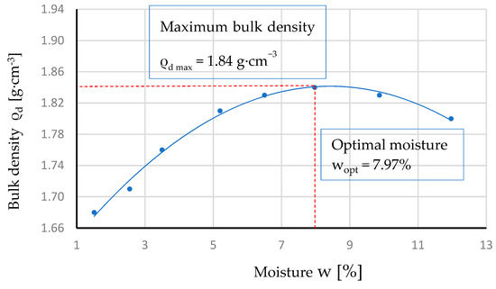
Figure 5.
Relationship of the bulk density of NATU ρd with moisture w.
The mixture was poured into special cylindrical forms. Samples were prepared in special cylindrical forms of dimensions of Ø 100 mm; h = 115 mm (Figure 6a,b). The samples were compacted in three layers, 25 strokes per layer, by means of the Proctor method according to standard EN 13286-2, using a Ø 50 mm compactor of a weight of 2.5 kg, falling freely from a height of 305 mm. In total, 18 cylindrical samples of the dimensions of Ø 100 mm and h = 115 mm were made, for compressive strength testing at 7, 28, and 56 days. There were six samples tested on each date of the test. Additionally, six cubic samples of dimensions of 10 × 10 × 10 cm3 were made for frost resistance testing.
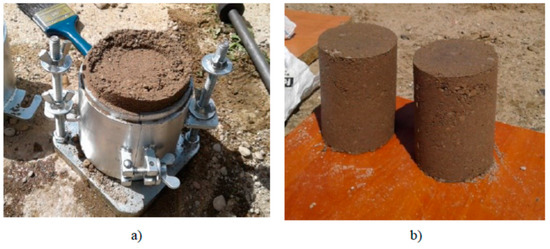
Figure 6.
Preparation of the samples made of fine aggregate with cement: cylindric form (a); samples (b).
Samples, having been prepared, were stored for 24 h in a mold, at a temperature of 20 ± 2 °C, followed by subsequent storage in a chamber, in the humidity of 95%–100% and temperature of 20 ± 2 °C and protected against drying. Three days before the test, the samples were submerged in water of the temperature of 20 ± 2 °C. One hour before compressive strength testing, the samples were taken out of the water and their surface was dried. Volume density, compressive strength, and frost resistance coefficient were tested.
The material with GEGA was proposed as a new solution. The mixture of the following composition was designed: CEM II/A-V 42.5 N, 205 kg; NATU, 90 kg; GEGA, 150 kg; water, 125 kg. The components of the mixture were mixed in a mechanical mixer. First, the slurry, composed of cement and water, was mixed for 2 min. Then, NATU was added and the mortar was mixed for next 1 min. GEGA was added to the mortar and mixed for 2 min.
The mixture was laid to special cylindrical molds of Ø 100 mm; h = 115 mm. The mix was compacted 25 times in two layers. The compaction method in accordance with the EN 206 standard is suggested by the authors. During concrete compacting, a hand-rammer of Ø 50 mm and weight of 1 kg was used. In order to ensure proper merger of the components, it is important to properly compact permeable ready mix with GEGA. It should be noted that too much compaction energy will reduce the porosity of the concrete, which, in turn, will reduce its permeability. Additionally, compacting shall be carried out in a way that prevents damage of the grains of the lightweight GEGA aggregate. For the compressive strength testing at 7, 28, and 56 days, 18 cylindrical samples of Ø 100 mm and h = 115 mm were made as shown in Figure 7a,b. There were six samples, tested on each assigned date of the tests. Additionally, 6 cubic samples of dimensions of 10 × 10 × 10 cm3 were made for frost resistance testing. Test samples were stored for 24 h in molds at a temperature of 20 ± 2 °C, followed by subsequent storage in a chamber at a humidity of 95%–100% and temperature of 20 ± 2 °C and protected against drying. One hour before the resistance test, the samples were taken out of the chamber and left to dry in the air at a temperature of 20 ± 2 °C. Volume density, compressive strength, and frost resistance coefficient were tested.
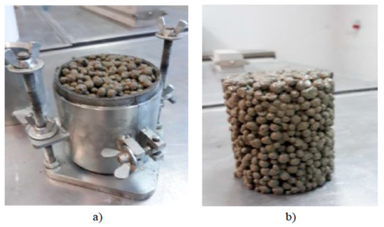
Figure 7.
Preparation of a sample mixture with GEGA (a). Sample of the mixture with GEGA for compression strength tests (b).
2.4. Test Methods
2.4.1. Volume Density Test and Porosity Test
Volume density was determined for three samples, made of NATU and for three samples of the material, made of GEGA:
where ρ0 is the volume density of the materials, m0 is the weight of the cylindrical sample, and V is the volume of cylindrical sample.
Volume density tests were carried out on cylindrical samples, intended for compressive strength testing. The volume of the sample was determined by measuring the sample’s dimensions.
Material porosity was marked as and defined as a ratio of the pores volume in the cylindrical sample to the total volume V of the sample. Porosity is the ratio of the volume of pass-through pores in a unit of the volume of a sample:
Due to the relationship:
Volume porosity is defined as:
where is the material porosity, V is the total volume, Vp is the volume of pores, and Vs is the volume of the solid material.
A porosity test was carried out on three cylindrical samples. The sample volume was determined by the measurement of its dimensions. The volume of open pores was determined by measuring water volume which permeated inside the sample. Water, filling in the pores, was measured by capillary forces, without any external pressure. The pore volume Vp was obtained by determining the mass of water that penetrated the pores of the sample. It has been assumed that 1 dm3 of water is equal to 1 kg.
2.4.2. Compressive Strength Tests
The compressive strength test was carried out in the Advantest 9, Controls, Liscate MI, Italy) in a uniaxial state of stress in accordance with the procedure, defined in EN 13286-41. For the compressive strength testing at 7, 28, and 56 days, 18 cylindrical samples of Ø 100 mm and h = 115 were made. On each assigned date six cylindrical samples were tested. Compressive strength of the material was determined on the basis of the arithmetic mean of the results for all six. It was assumed that none of the results can deviate from the mean more than 10%. Standard deviation was determined.
2.4.3. Frost Resistance Coefficient Tests
Samples for frost resistance coefficient test were stored for 28 days in a chamber with the humidity of 95%–100%, and temperature of 20 ± 2 °C. Then, they were submerged in water for 24 h, and placed in a frost chamber. Then they underwent 14 frost and thaw cycles. One cycle procedure involves freezing the samples for 8 h in the temperature of −23 ± 2 °C and thawing them for 16 h in the temperature of 18 ± 2 °C. Frost resistance coefficient was determined for three samples in accordance with Equation (5). The average compression strength RcZ−O was adopted for the calculations. The following frost resistance coefficient was adopted:
for Mmin = 0.7; where is the average compressive strength of the samples, subjected to freeze-thaw cycles, and Rc is the average compressive strength of reference samples (cared in air and water).
3. Results and Discussion
3.1. Volume Density Tests
The volume density of NATU and GEGA were determined at seven and 28 days, by measuring and weighing cylindrical samples according to Equation (1). The result is the arithmetic mean of the values, determined for six NATU and six GEGA cylindrical samples. The results are presented in Figure 8.
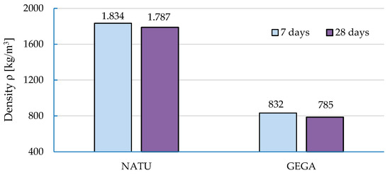
Figure 8.
Change in apparent density.
3.2. Compressive Strength Tests
The average compressive strength of NATU, tested on six samples, was 1.3 MPa (standard deviation s = 0.2 MPa), while the average compressive strength of the six samples (cylinders) on the 28th day was 3.2 MPa (s = 0.4 MPa). At 56 days, the average compressive strength was 3.8 MPa (s = 0.3 MPa). It is shown in Figure 9a. Compressive strength test of the material with GEGA was performed at seven days on six cylindrical samples and it was 1.9 MPa (s = 0.2 MPa), while on the 28th day the average compressive strength of the six cylindrical samples was 3.7 MPa (s = 0.3 MPa). At 56 days, the average compressive strength was 4.9 (s = 0.7 MPa). Test results are presented in Figure 9b.
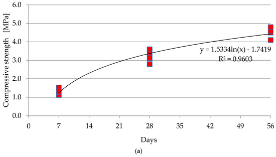
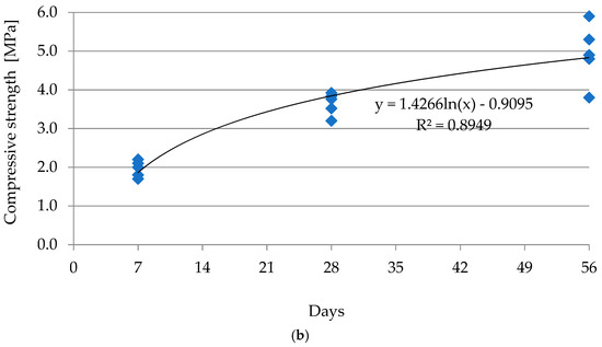
Figure 9.
Growth of compression strength with time: (a) NATU, (b) GEGA.
The carried out frost resistance tests of NATU and GEGA have shown that both materials have met Polish Technical Requirements WT-5 2010, “Mixtures bound with a hydraulic binder for national roads” and that the frost resistance index, calculated according to Equation (5), was higher than the required minimum Mmin = 0.7, where the NATU frost resistance index was 0.74 and the GEGA frost resistance index was 0.94.
4. Analysis and Application of the Traditional Pavement Structure and with Use of a GEGA Permeable Layer
Taking into account favorable properties of permeable concrete, the analysis of the possibilities to apply this material for a road course in typical solutions for pavement structure was carried out in accordance with Polish requirements [45,46].
The procedure for the calculation of the required thickness of the lightweight GEGA permeable concrete course, as an alternative to a typical frost protection course and improved soil sub-grade, was carried out in accordance with the guidelines, contained in [47,48,49]. For each of the analyzed solutions the values of elastic deflections “w” on the surface of the improved sub-grade course and on the surface of the sub-base courses of the pavement structure were determined. Calculations were carried out using BISAR 3.0 software (Bitumen Stress Analysis in Roads, Shell, Gdansk, Poland). The required Eequivalent substitute modulus on the surface of the analyzed layers was calculated by means of using the Boussinesq equation (Equation (6)) from the theory of elastic half-space, which is the following:
where Eequivalent is the substitute modulus, determined on the surface of sub-base course layer of pavement structure and on the surface of improved subgrade, MPa; q is the contact pressure of the wheel q = 0.65 kPa; D is the substitute diameter of the wheel tract, D = 0.313 m; ν is Poisson’s ratio, ν = 0.3; and w is the deflection on the surface of road profile, m.
Table 4, Table 5 and Table 6 summarize the proposal of application of lightweight concrete sub-grade course containing GEGA material instead of traditional frost-resistant layer and improved sub-grade course. Calculations of the required thickness of the GEGA concrete road pavement layer for flexible and rigid pavements were carried out, depending on the traffic category, i.e., the traffic load. The results of the calculations, presented in Table 4, Table 5 and Table 6, refer to three selected representative road traffic categories, according to [44], representing heavy, medium, and light traffic.
Table 4.
Resulting structural layers of flexible and rigid pavements—traditional and permeable concrete—made of GEGA, solutions for heavy traffic.
Table 5.
Resulted structural layers of flexible and rigid pavements—traditional and permeable concrete, made of GEGA, solutions for medium traffic.
Table 6.
Resulted structural layers of flexible and rigid pavements—traditional and permeable concrete, made of GEGA, solutions for light traffic.
The computational analysis showed that it is possible to replace the traditional solution of the frost protection course and the improved soil sub-grade course with a single course of lightweight concrete containing GEGA material. The proposed alternative solution which may be used in both flexible and rigid pavement structures, features the required load-bearing capacity and durability parameters.
5. Conclusions
The completed tests and analyses allow the following conclusions to be drawn:
- The research confirmed that the road sub-grade of permeable concrete, made of GEGA, has similar mechanical properties to a sub-grade with NATU and can function as a frost protection layer for the road sub-base. Additionally, the material with GEGA is permeable to liquids. Therefore, it is possible to obtain a lightweight material with GEGA of the mechanical properties, meeting the requirements, imposed on the frost protection layer, made of natural aggregate NATU, stabilized with a hydraulic binder. Thus, it is possible to substitute the sub-grade and the frost-protection sub-base with a single layer, made of lightweight material with GEGA.
- The analysis has shown that practical implementation of the proposed solution is technically justified in the case of flexible and rigid pavements. Application of the recycled material with GEGA allows an effective construction of the road pavement, maintaining the required load-bearing capacity and durability parameters.
- The proposed solution, concerning the use of recycled materials is fully coherent with the idea of environment protection and sustainable development of the economy, not only in Europe, but worldwide. The application of GEGA allows limiting the mining of the NATU materials, due to which environmental degradation can be reduced.
- It is recommended to carry out further research on the LCC (life cycle costs) analysis, conducted for flexible and rigid pavements, for selected traffic categories and for two technologies of road pavement construction [50,51,52].
- Further research into lightweight aggregate’s compressive strength increase shall be carried out and the elastic modulus shall be determined, as well as volume flow rate, depending on the porosity.
- Rapid development in industrial application of GEGA and other lightweight aggregates, manufactured from recycled materials, requires a proposal and implementation of the design methods for the materials with synthetic aggregates and recycled aggregates.
Author Contributions
Conceptualization: M.K.; methodology: M.K. and M.P.; validation: A.K. and B.G.; formal analysis: M.K.; investigation: M.K., M.P., and B.G.; resources: M.K. and A.K.; data curation: A.K.; writing—original draft preparation: M.K., A.K., and M.P.; writing—review and editing: M.K., B.G., and A.K.; supervision: M.K.; project administration: M.K. and A.K.; funding acquisition: M.K.
Funding
This research received no external funding.
Conflicts of Interest
The authors declare no conflict of interest.
References
- Karim, Y.; Khan, Z.; Alsoufi, M.S.; Yunus, M. A Review on Recycled, Aggregates for the Construction Industry. Am. J. Civ. Eng. Archit. 2016, 4, 27–33. [Google Scholar] [CrossRef]
- A Sustainable Aggregates Industry for a Sustainable Europe. Available online: http://www.uepg.eu/ (accessed on 7 May 2019).
- Sikora, P.; Augustyniak, A.; Cendrowski, K.; Horszczaruk, E.; Rucinska, T.; Nawrotek, P.; Mijowska, E. Characterization of mechanical and bactericidal properties of cement mortars containing waste glass aggregate and nanomaterials. Materials 2016, 9, 701. [Google Scholar] [CrossRef] [PubMed]
- Najduchowska, M.; Rozycka, K.; Rolka, G. Ocena możliwości wykorzystania stłuczki szklanej w przemyśle budowlanym w aspekcie jej wpływu na środowisko naturalne. Prace ICiMB 2014, 17, 1–10. (In Polish) [Google Scholar]
- Sikora, P.; Horszczaruk, E.; Skoczylas, K.; Rucinska, T. Thermal properties of cement mortars containing waste glass aggregate and nanosilica. Procedia Eng. 2017, 196, 159–166. [Google Scholar] [CrossRef]
- Du, H.; Tan, K.H. Concrete with recycled glass as fine aggregates. ACI Mater. J. 2014, 111, 47–58. [Google Scholar]
- Chung, S.-Y.; Elrahman, M.; Sikora, P.; Rucinska, T.; Horszczaruk, E.; Stephan, D. Evaluation of the Effects of Crushed and Expanded Waste Glass Aggregate on the Material Properties of Lightweight Concrete Using Image-Based Approaches. Materials 2017, 10, 1354. [Google Scholar] [CrossRef] [PubMed]
- Lo, T.Y.; Tang, W.C.; Cui, H.Z. The effects of aggregate properties on lightweight concrete. Build. Environ. 2007, 42, 3025–3029. [Google Scholar] [CrossRef]
- Waste Statistics. Available online: https://ec.europa.eu/eurostat/statistics-explained/index.php/Waste_statistics (accessed on 7 May 2019).
- Kurpińska, M.; Ferenc, T. Application of lightweight cement composite with foamed glass aggregate in shell structures. Shell Struct. Theory Appl. 2018, 4, 549–552. [Google Scholar]
- Jamshidi, A.; Kurumisawa, K.; Nawa, T.; Igarashi, T. Performance of pavements incorporating waste glass: The current state of the art. Renew. Sustain. Energy 2016, 64, 211–236. [Google Scholar] [CrossRef]
- Ganjian, E.; Jalull, G.; Sadeghi-Pouya, H. Using waste materials and by-products to produce concrete paving blocks. Constr. Build. Mater. 2015, 77, 270–275. [Google Scholar] [CrossRef]
- Arnold, G.; Werkmeister, S.; Alabaster, D. The effect of adding recycled glass on the performance of base course aggregate. N. Z. Transp. Agency Res. Rep. 2008, 351, 40. [Google Scholar]
- Ulsen, C.; Kahn, H.; Hawlitschek, G.; Masini, E.A.; Angulo, S.C.; John, V.M. Production of recycled sand from construction and demolition waste. Constr. Build. Mater. 2013, 40, 1168–1173. [Google Scholar] [CrossRef]
- Shi, C.; Zheng, K. A review on the use of waste glasses in the production of cement and concrete. Resour. Conserv. Recycl. 2007, 52, 234–247. [Google Scholar] [CrossRef]
- Domagala, L. Structural lightweight aggregate concrete. In Civil Engineering; Cracow University of Technology: Cracow, Poland, 2014. (In Polish) [Google Scholar]
- Šeputytė-Jucikė, J.; Sinica, M. The effect of expanded glass and polystyrene waste on the properties of lightweight aggregate concrete. Eng. Struct. Technol. 2016, 8, 31–40. [Google Scholar] [CrossRef]
- Gonawala, R.J.; Khapre, S.; Kumar, R.; Chauhan, K.A. Suitability of EAF slag and GGBFS mix as cementitious base/sub-base layer for low volume road construction. Int. J. Geotech. Eng. 2019. [Google Scholar] [CrossRef]
- Biswal, D.R.; Sahoo, U.C.; Dash, S.R. Mechanical characteristics of cement stabilised granular lateritic soils for use as structural layer of pavement. Road Mater. Pavement Des. 2018. [Google Scholar] [CrossRef]
- Canakci, H.; Güllü, M.I.; Dwle, K. Effect of Glass Powder Added Grout for Deep Mixing of Marginal Sand with clay. Arab. J. Sci. Eng. 2018, 43, 1583–1595. [Google Scholar] [CrossRef]
- Del Rey, I.; Ayuso, J.; Barbudo, A.; Galvín, A.P.; Agrela, F.; de Brito, J. Feasibility study of cement-treated 0–8 mm recycled aggregates from construction and demolition waste as road base layer. Road Mater. Pavement Des. 2015, 17, 678–692. [Google Scholar] [CrossRef]
- Poutos, K.H.; Alani, A.M.; Walden, P.J.; Sangha, C.M. Relative temperature changes within concrete made with glass aggregates. Constr. Build. Mater. 2006, 22, 557–565. [Google Scholar] [CrossRef]
- Park, S.B.; Lee, B.C.; Kim, J.H. Studies on mechanical properties of concrete containing waste glass aggregates. Cement Concrete Res. 2004, 34, 2181–2189. [Google Scholar] [CrossRef]
- Wang, H.; Huang, W. Durability of self-consolidating concrete using waste LCD glass. Constr. Build. Mater. 2010, 24, 1008–1013. [Google Scholar] [CrossRef]
- Liu, S.; Wang, S.; Tang, W.; Hu, N.; Wei, J. Inhibitory Effect of Waste Glass Powder on ASR expansion induced by waste glass aggregate materials. Materials 2015, 8, 6849–6862. [Google Scholar] [CrossRef] [PubMed]
- Rashad, A.M. Recycled waste glass as fine aggregate replacement in cementitious materials based on Portland cement. Const. Build. Mater. 2014, 72, 340–357. [Google Scholar] [CrossRef]
- Xi, Y.; Li, Y.; Xie, Z.; Lee, J.S. Utilization of solid wastes (waste glass or rubber particles) as aggregate in concrete. In Proceedings of the International Workshop on Sustainable Development and Concrete Technology, Beijing, China, 20–21 May 2004. [Google Scholar]
- Shayan, A.; Xu, A. Performance of glass powder as a pozzolanic materials in concrete: A field trial on concrete slabs. Cement Concrete Res. 2006, 36, 457–468. [Google Scholar] [CrossRef]
- Gallaway, B.M. A Manual on the Use of Lightweight Aggregate in Flexible Pavement Systems Expand; Shale Clay Slate Institute: Washington, DC, USA, 1969. [Google Scholar]
- Arulrajah, A.; Disfani, M.; Horpibulsuk, S. Sustainable Usage of Construction and Demolition Materials in Roads and Footpaths. Sustain. Issues Civ. Eng. 2017. [Google Scholar] [CrossRef]
- Airey, G.D.; Collo, A.C.; Thom, N.H.; Zoorob, S.E.; Shiratori, A. Laboratory evaluation of secondary aggregates in bituminous mixtures. J. Assoc. Asphalt Paving Technol. 2004, 73, 731–769. [Google Scholar]
- Limbachiya, M.C. Bulk engineering and durability properties of washed glass sand concrete. Constr. Build. Mater. 2008, 23, 1078–1083. [Google Scholar] [CrossRef]
- Segui, P.; Dore, G.; Bilodeau, J.-P.; Morasse, S. Innovative materials for road insulation in cold climates: Foam glass aggregate. In Proceedings of the 2016 Conference and Exhibition of the Transportation Association of Canada—Efficient Transportation—Managing the Demand, Toronto, ON, Canada, 22–28 September 2016. [Google Scholar]
- Omidimoaf, E.; Rajabi, A.M.; Abdelgader, H.S.; Kurpińska, M.; Wilde, K. Effect of coarse grain aggregate on strength parameters of two-stage concrete. Mater. Bud. 2019, 3, 1–3. [Google Scholar] [CrossRef]
- Mariak, A.; Kurpińska, M.; Wilde, K. Maturity curve for estimating the in-place strength of high performance concrete. MATEC Web Conf. 2019, 262, 06007. [Google Scholar] [CrossRef][Green Version]
- Mariak, A.; Kurpińska, M. The effect of macro polymer fibres length and content on the fibre reinforced concrete. MATEC Web Conf. 2018, 219, 03004. [Google Scholar] [CrossRef][Green Version]
- Kurpińska, M.; Małasiewicz, A. Der Betonschutz vor der Wirkung der Aggressiven Umgebung; Tagungsbericht//Ibausil, 15. Internationale Baustofftagung; Bauhaus-Universität Weimar/F.A. Finger-Institut für Baustoffkunde: Weimar, Germany, 2003. [Google Scholar]
- Kurpińska, M. Properties of concrete impregnated using epoxy composition. Roads Bridges 2011, 10, 59–80. [Google Scholar]
- Al-Sibahy, A.; Edwards, R. Mechanical and thermal properties of novel lightweight concrete mixtures containing recycled glass and metakaolin. Constr. Build. Mater. 2012, 31, 157–167. [Google Scholar] [CrossRef]
- Grzyl, B.; Apollo, M.; Miszewska-Urbańska, E.; Kristowski, A. The criteria for evaluation and selection the best tender applied by the authorities in Poland and selected EU countries. MATEC Web Conf. 2018, 219, 04006. [Google Scholar] [CrossRef][Green Version]
- Grzyl, B.; Miszewska-Urbańska, E.; Apollo, M. The life cycle cost of a building from the point of view of environmental criteria of selecting the most beneficial offer in the area of competitive tendering. Web Conf. 2017, 17, 00028. [Google Scholar] [CrossRef]
- Frydenlund, T.E.; Aaboe, R. Granulated Expanded Glass Aggregate—A new vision in road construction. In Proceedings of the XXII PIARC World Road Congress, Durban, South Africa, 19–25 October 2003. [Google Scholar]
- Kurpińska, M.; Ferenc, T. Effect of porosity on physical properties of lightweight cement composite with foamed glass aggregate. ITM Web Conf. 2017, 15, 6005. [Google Scholar] [CrossRef]
- Pszczoła, M.; Judycki, J.; Ryś, D. Evaluation of pavement temperatures in Poland during winter conditions. Transp. Res. Procedia 2016, 14, 738–747. [Google Scholar] [CrossRef]
- GDDKiA. Catalogue of Typical Flexible and Rigid Road Pavement Structures, Order No. 31 of the General Director for National Roads and Motorways of 16.06.2014; Generalna Dyrekcja Drog Krajowych i Autostrad: Warszawa, Poland, 2014.
- GDDKiA. Catalogue of Typical Flexible and Rigid Road Pavement Structures, Order No. 30 of the General Director for National Roads and Motorways of 16.06.2014; Generalna Dyrekcja Drog Krajowych i Autostrad: Warszawa, Poland, 2014.
- Cheng, A.; Hsu, H.-M.; Chao, S.-J.; Lin, K.-L. Experimental Study on Properties of Pervious Concrete Made with Recycled Aggregate. Int. J. Pavement Res. Technol. 2011, 4, 104–110. [Google Scholar]
- Judycki, J.; Jaskuła, P.; Pszczoła, M.; Ryś, D.; Jaczewski, M.; Alenowicz, J.; Dołżycki, B.; Stienss, M. Analyses and Designing of Flexible and Semi-Rigid Road Pavement Structures; Wydawnictwa Komunikacji i Łączności: Warsaw, Poland, 2014. [Google Scholar]
- Judycki, J.; Jaskuła, P.; Pszczoła, M.; Ryś, D.; Jaczewski, M.; Alenowicz, J.; Stienss, M. New Polish Catalogue of Typical Flexible and Semi-Rigid Pavements. MATEC Web Conf. 2017, 122, 4002. [Google Scholar] [CrossRef]
- Kristowski, A.; Grzyl, B.; Kurpińska, M.; Pszczoła, M. The rigid and flexible road pavements in terms of life cycle costs. In Proceedings of the Creative Construction Conference, Ljubljana, Slovenia, 30 June–3 July 2018. [Google Scholar] [CrossRef]
- Grzyl, B.; Siemaszko, A. The Life Cycle Assessment and Life Cycle Cost in public works contracts. Web Conf. 2018, 44, 00047. [Google Scholar] [CrossRef]
- Grzyl, B.; Kristowski, A.; Jamroz, K.; Gobis, A. Methods of estimating the cost of traffic safety equipment’s life cycle. MATEC Web Conf. 2017, 122, 02003. [Google Scholar] [CrossRef]


© 2019 by the authors. Licensee MDPI, Basel, Switzerland. This article is an open access article distributed under the terms and conditions of the Creative Commons Attribution (CC BY) license (http://creativecommons.org/licenses/by/4.0/).