Abstract
The results of the investigation on tensile stress dependence of the SAMR (small angle magnetization rotation) signal in soft magnetic amorphous ribbons are presented. Exemplary results for commercially available, negatively magnetostrictive 2705M, 2714A, and 6030D amorphous ribbons show significant stress dependence, in contrast to positively magnetostrictive 2826MB alloy. The magnetoelastic hysteresis of the obtained characteristics is compared, as well as the influence of the biasing H field and supply current variations. Based on the results, 2705M alloy with near-zero negative magnetostriction is proposed as best suited for a SAMR-based, magnetoelastic force sensor.
1. Introduction
Soft magnetic amorphous ribbons are widely known for their unique mechanical and magnetic properties [1,2,3,4,5,6,7]. The magnetomechanical effects play an important role in the utilization of these materials [8,9], with magnetostriction and inverse magnetomechanical (Villari) effect [10] as main examples. The magnetostriction is of great concern due to the connection between the saturation magnetostriction constant and the relative permeability of the amorphous ribbon [11]. Because the magnetostriction is undesired for ultra-soft magnetic materials, there is an ongoing effort which brings numerous magnetostriction measurement methods [12,13].
One of the simplest of these is the small angle magnetization rotation [SAMR] method, which, due to its indirect nature, can achieve significant resolution, up to 10−9 [14]. It is, however, mostly applicable to near-zero magnetostrictive materials, preferably with negative magnetostriction [13].
The SAMR method utilizes the dependence of magnetization rotation angle θ in the saturated sample on saturating the H‖ field value, small excitation AC field value H⊥, tensile stress σ, and saturation magnetostriction constant λS. The saturating DC field H‖ is typically supplied by a long solenoid or Helmholtz coils axial with the length of the sample, while the H⊥ field is provided by a pair of coils [15], yoke [16] or even AC electric current along the sample [14]. The magnetization rotation angle is measured with the help of a measurement coil along the sample, as there is induced voltage of double the excitation H⊥ field frequency [15].
where N is the number of turns of the sense coil, S is the cross-sectional area of the ribbon, MS is the saturation magnetization, θ is the angle between magnetization vector and ribbon axis. The angle θ can be obtained by minimization of total free energy [14].
From this relation, we obtain the widely known equation for λS, given that we vary only the tensile stress σ and H‖ field keeping the e2f signal constant [13].
The above equations were modified by later researchers to take into account angle skew, local anisotropy, etc. [15], in pursuit of 10−9 resolution of λS measurement. Further works also included such aspects as the influence of torsion on saturation magnetostriction, etc. [17,18]. All of those works were focused on the measurement of saturation magnetostriction of a given material.
However, Equations (1) and (2) suggest new possible utilization of the SAMR method, which is the purpose of this paper. There is ongoing effort to develop new kinds of force sensors [19], along with magnetoelastic force sensors, play a unique role [20]. While the SAMR method was intended for research into magnetostriction behavior of soft magnetic materials, the above equations, as well as measurement practice, suggest a significant influence of tensile stresses on the magnetization rotation angle θ, and thus on the signal induced in measurement coil.
It is, therefore, possible to develop a new kind of magnetoelastic force sensor, utilizing a non-balanced SAMR signal. Both above, simplified equations, as well as more sophisticated ones [14], give monotonous and unambiguous dependence of induced voltage on applied stress, which is appropriate for sensing applications. Moreover, the SAMR signal is better for materials with near-zero magnetostriction [13], which is interesting and uncommon for magnetoelastic sensor construction [21].
As the SAMR method theory relies on some simplifying assumptions, the influence of tensile stress on SAMR signal in commercial amorphous ribbons is investigated, to propose the best-suited material for new SAMR-based magnetoelastic sensor development. As can be seen, due to anelastic phenomena, magnetoelastic hysteresis [22] and apparent Villari point [23,24,25,26], obtained characteristics are far from monotonous, with distinct local maximum, nor unambiguous, due to magnetoelastic hysteresis observed in most of the magnetoelastic systems. Based on these experimental results, the most promising of the tested materials is proposed.
2. Materials and Methods
2.1. Utilized Samples
The ribbon samples used in the investigation were made from commercially available, amorphous alloys listed in Table 1. Co70Fe5Ni2Mo5B3Si15, Co66Fe4B14Si15Ni1, and Co84Fe1.5Mo2Mn1.5Si7B2 alloys were chosen due to their varying negative magnetostriction, and Fe40Ni38Mo4B18 due to positive magnetostriction, for comparison purposes. The ribbons were prepared by the manufacturers with standard rotating cylinder rapid quench technique [27].

Table 1.
Essential parameters of investigated samples, according to the manufacturer’s [28,29].
2.2. Measurement Method
The measurements were carried out on a specially designed measurement system. Figure 1 presents the schematic diagram of this system.
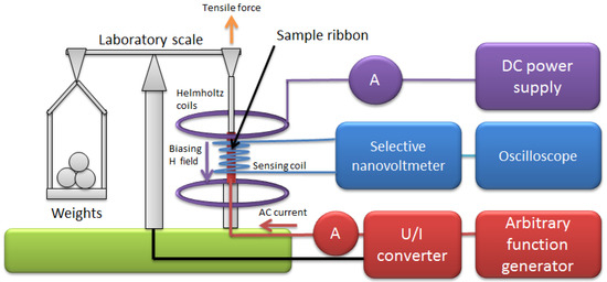
Figure 1.
Schematic diagram of the developed small angle magnetization rotation (SAMR) system.
The sample ribbons were mounted coaxially with a sensing coil and biasing Helmholtz coil in soldered mounts. The tensile stress was generated in the samples using an equal-arms laboratory scale and weights, which allows for very low values of initial stress and its precise control.
The Helmholtz coils (ESP, Warsaw, Poland) were connected to a variable bipolar DC power supply (P314, Meratronik, Warsaw, Poland) and ammeter (TH1961, Tonghui, Changzhou, China) to set a stable DC biasing/saturating field H‖. The biasing field was set to 160 A/m, which was enough to saturate the utilized high-permeability samples.
The exciting transversal field H⊥ was generated in the sample by means of an AC electrical current passed along it, with help of an arbitrary function generator (SDG1025, Siglent, Helmond, The Netherlands) connected to a voltage-current converter (RDM-2a, WUT, Warsaw, Poland) and ammeter (TH1961, Tonghui, Changzhou, China). The AC current was set to 300 mA, which is similar to common practice [14]. The frequency was 432 Hz to suppress the signal noise level.
The SAMR signal induced in the sensing coil of 1000 turns was measured with the sharp band-pass filter and amplifier (Selective Nanovoltmeter 233, Unipan, Warsaw, Poland), the output of which was fed to an oscilloscope for monitoring (model 5228, Schlumberger/Sefram, St Etienne, France).
3. Results and Discussion
First, three of the investigated materials exhibited the significant influence of tensile stress on the magnetization rotation angle, as evidenced by characteristics of induced voltage presented in Figure 2, Figure 3 and Figure 4. The voltage measurement uncertainty was smaller than the size of points used (1% at most). The uncertainty of applied stress was less than 0.5% and was mostly due to sample cross-section uncertainty.
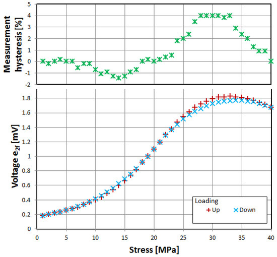
Figure 2.
Dependence of induced e2f voltage on tensile stress, alloy 2705M.
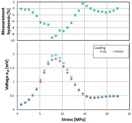
Figure 3.
Dependence of induced e2f voltage on tensile stress, alloy 2714A.
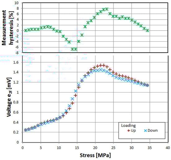
Figure 4.
Dependence of induced e2f voltage on tensile stress, alloy 6030D.
The samples were gradually loaded with increasing stress up to full load, and then stress gradually decreased. Thus, measurement hysteresis was investigated, which is, for the most part, due to magnetoelastic hysteresis of the sample’s material, and is one of the ‘bottlenecks’ of accuracy for magnetoelastic-based force sensors, and needs additional nontrivial compensation [30,31].
All three of investigated negative-magnetostrictive amorphous alloys exhibited similar behavior, with a distinct maximum for a particular value of stress, reminiscent of the Villari reversal point of typical magnetoelastic characteristics [23]. From Equations (1) and (2), it is evident that the angle θ, and thus the obtained signal e2f, depends on the stress-induced anisotropy of the material. However, for a given set of material constants MS and λS, the stress-induced voltage should rise monotonically. The local maximum and gradual fall of the induced signal can be explained by the stress-induced change in value and sign of the saturation magnetostriction λS. The same effect was proposed as responsible for the Villari reversal point in standard magnetoelastic characteristics [26].
The measurement hysteresis was most profound near the local maximum, reaching as high as −9% for 2714A alloy.
Alloy 2705M exhibited both the widest range of stress before reaching local maximum and lowest values of measurement hysteresis, giving about 1% uncertainty in the 0 to 20 MPa range.
The characteristic of positively magnetostrictive 2836MB alloy is different (Figure 5)—measurable changes took place for much lower stress values, and there was no distinct local maximum (which would correspond to standard magnetoelastic characteristics [32]). The overall signal amplitude was nearly 100 times smaller than for the negative-magnetostriction samples, however, which is one of the reasons why standard SAMR determination of λS is best suited to negative-magnetostrictive materials.
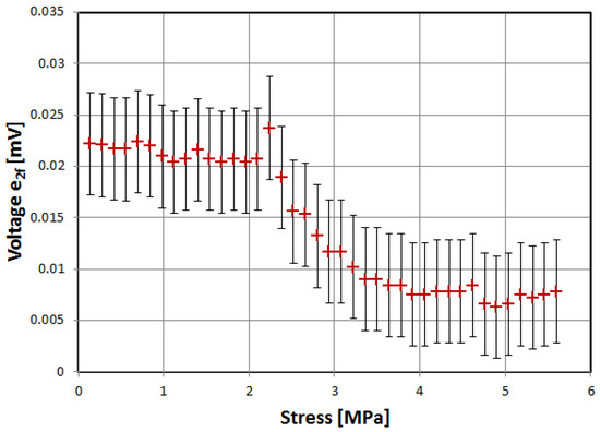
Figure 5.
Dependence of induced e2f voltage on tensile stress, alloy 2826MB. Due to the low-level signal, and thus high uncertainty, measurement hysteresis was not recorded.
Figure 6 and Figure 7 show the relative change of induced voltage e2f, and thus magnetization rotation angle θ, on the parallel biasing H‖ field and, indirectly, transversal H⊥ field variations. The characteristics are surprisingly similar for all of the tested alloys, and correspond with Equations (1) and (2)—the induced voltage rises for rising H⊥, and falls for rising H‖.
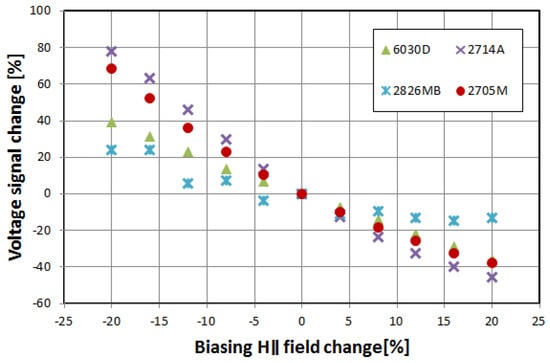
Figure 6.
Relative change of the induced e2f voltage in the function of biasing H‖ field change.
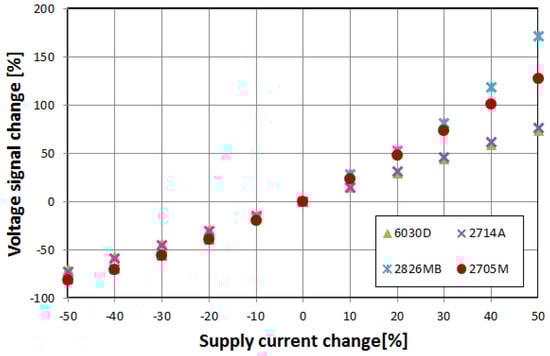
Figure 7.
Relative change of the induced e2f voltage in the function of supply current change, and thus proportional exciting H⊥ field change.
The sensitivity to the external magnetic field is similar to the orthogonal fluxgates operational principle [33]. It is interesting to note that for the samples of the same size and shape, the sensitivity is almost the same, regardless of sample relative permeability. It is mostly due to assumed technical magnetic saturation of the material—in Equations (1) and (2) the relative permeability of the samples is absent.
4. Conclusions
The measurement stand capable of measurements of tensile stress influence on the small angle magnetization rotation signal was presented. The e2f(σ) characteristics of four commercial amorphous ribbons were investigated, including the bane of magnetoelastic technology, which is magnetoelastic hysteresis. The negative-magnetostrictive ribbons exhibited similar characteristics, with distinct local maximum similar to the Villari reversal point. The measurement hysteresis was unacceptably high for 2714A and 6030D alloys. The positive-magnetostrictive alloy 2826MB is unsuitable for further investigation due to the very low-level signal obtained. Thus, opposite to typical B(σ) or µ(σ) magnetoelastic force sensors development [34,35,36], near-zero, negative magnetostriction 2705M alloy is proposed as the most promising for unbalanced SAMR-based magnetoelastic force sensor construction.
The responsivity frequency bandwidth of the proposed sensor would be limited by the supply current frequency. The measurement range is limited by the Villari reversal point. Thus reproducible results are to be expected in the 0 to 25 MPa range of the core stress. For the presented case, it translates to approximately the 0 to 50 N force range. This range is, however, scalable with the core cross-section.
Author Contributions
Every stage of the research and writing was conducted by M.N.
Funding
This research was funded by the statutory funds of Institute of Metrology and Biomedical Engineering, Warsaw University of Technology.
Conflicts of Interest
The author declares no conflict of interest. The funders had no role in the design of the study; in the collection, analyses, or interpretation of data; in the writing of the manuscript, and in the decision to publish the results.
References
- Egami, T. Magnetic amorphous alloys: physics and technological applications. Rep. Prog. Phys. 1984, 47, 1601–1725. [Google Scholar] [CrossRef]
- Schuh, C.; Hufnagel, T.; Ramamurty, U. Mechanical behavior of amorphous alloys. Acta Mater. 2007, 55, 4067–4109. [Google Scholar] [CrossRef]
- Nosenko, V.K.; Maslov, V.V.; Kirilchuk, V.V.; Kochkubey, A.P. Some industrial applications of amorphous and nanocrystalline alloys. J. Phys. Conf. Ser. 2008, 98, 072016. [Google Scholar] [CrossRef]
- Egami, T.; Flanders, P.J.; Graham, C.D., Jr. Amorphous alloys as soft magnetic materials. AIP Conf. Proc. 1975, 24, 697–701. [Google Scholar]
- Hasegawa, R. Applications of amorphous magnetic alloys. Mater. Sci. Eng. A 2004, 375, 90–97. [Google Scholar] [CrossRef]
- Makhotkin, V.; Shurukhin, B.; Lopatin, V.; Marchukov, P.; Levin, Y. Magnetic field sensors based on amorphous ribbons. Sens. Actuators A Phys. 1991, 27, 759–762. [Google Scholar] [CrossRef]
- Okazaki, Y.; Ueno, K. Magnetic shielding by soft magnetic materials in alternating magnetic field. J. Magn. Magn. Mater. 1992, 112, 192–194. [Google Scholar] [CrossRef]
- Callen, E.; Callen, H.B. Magnetostriction, Forced Magnetostriction, and Anomalous Thermal Expansion in Ferromagnets. Phys. Rev. 1965, 139, A455–A471. [Google Scholar] [CrossRef]
- Lee, E.W. Magnetostriction and magnetomechanical effects. Rep. Prog. Phys. 1955, 18, 184. [Google Scholar] [CrossRef]
- Villari, E. Ueber die aenderungen des magnetischen moments, welche der zug und das hindurchleiten eines galvanischen stroms in einem stabe von stahl oder eisen hervorbringen (About the changes of the magnetic moment produced by the pulling and passing of a galvanic current in a rod of steel or iron). Ann. Phys. 1865, 202, 87–122. (In German) [Google Scholar]
- Jiles, D.C. Introduction to Magnetism and Magnetic Materials; CRC Press: Boca Raton, FL, USA, 2015. [Google Scholar]
- Williams, S.R. Some experimental methods in magnetostriction. J. Opt. Soc. Am. 1927, 14, 383. [Google Scholar] [CrossRef]
- Grossinger, R.; Sassik, H.; Holzer, D.; Pilmayr, N. Accurate measurement of the magnetostriction of soft magnetic materials. In Proceedings of the 9th International Workshop on 1&2 Dimensional Magnetic Measurement Testing, Częstochowa, Poland, 18–19 September 2006. [Google Scholar]
- Hernando, A.; Vazquez, M.; Madurga, V.; Kronmuller, H. Modification of the saturation magnetostriction constant after thermal treatments for the Co 58 Fe 5 Ni 10 B 16 Si 11 amorphous ribbon. J. Magn. Magn. Mater. 1983, 37, 161–166. [Google Scholar] [CrossRef]
- Narita, K.; Yamasaki, J.; Fukunaga, H. Measurement of saturation magnetostriction of a thin amorphous ribbon by means of small-angle magnetization rotation. IEEE Trans. Magn. 1980, 16, 435–439. [Google Scholar] [CrossRef]
- Alves, F.; Houeée, P.; Leécrivain, M.; Mazaleyrat, F. New design of small-angle magnetization rotation device: Evaluation of saturation magnetostriction in wide thin ribbons. J. Appl. Phys. 1997, 81, 4322–4324. [Google Scholar] [CrossRef]
- Talaat, A.; Zhukova, V.; Ipatov, M.; Blanco, J.M.; Gonzalez, J.; Zhukov, A. Impact of Stress Annealing on the Magnetization Process of Amorphous and Nanocrystalline Co-Based Microwires. Materials 2019, 12, 2644. [Google Scholar] [CrossRef] [PubMed]
- Chubykalo, O.; González, J.; Aragoneses, P.; Blanco, J.; Domínguez, L.; Gonzalez, J.; González, J. Saturation magnetostriction dependence on torsion in amorphous wire as measured by modified small angle magnetization rotation method. J. Magn. Magn. Mater. 1997, 169, 169–177. [Google Scholar] [CrossRef]
- Stefanescu, D.M. Handbook of Force Transducers: Principles and Components; Springer Science & Business Media: Berlin, Germany, 2011. [Google Scholar]
- Bieńkowski, A.; Szewczyk, R.; Salach, J. Industrial application of magnetoelastic force and torque sensors. Acta Phys. Pol. A 2010, 118, 1008–1009. [Google Scholar] [CrossRef]
- Švec, P.; Szewczyk, R.; Salach, J.; Jackiewicz, D.; Šlvec, P.; Bienkowski, A.; Hosko, J. Magnetoelastic Properties of selected amorphous systems tailored by thermomagnetic treatment. J. Electr. Eng. 2014, 65, 259–261. [Google Scholar] [CrossRef]
- Kraus, L.; Švec, P. Magnetoelastic hysteresis of amorphous ribbons. J. Appl. Phys. 2003, 93, 7220–7222. [Google Scholar] [CrossRef]
- Szewczyk, R.; Bieńkowski, A. Magnetoelastic Villari effect in high-permeability Mn–Zn ferrites and modeling of this effect. J. Magn. Magn. Mater. 2003, 254, 284–286. [Google Scholar] [CrossRef]
- Mihalca, I.; Ercuta, A.; Ionascu, C. The Villari effect in Fe–Cr–B amorphous ribbons. Sens. Actuators A Phys. 2003, 106, 61–64. [Google Scholar] [CrossRef]
- Szewczyk, R.; Bieńkowski, A.; Kolano, R. Influence of nanocrystalization on magnetoelastic Villari effect in Fe73.5Nb3Cu1Si13.5B9 alloy. Cryst. Res. Technol. 2003, 38, 320–324. [Google Scholar] [CrossRef]
- Bieńkowski, A. Magnetoelastic Villari effect in Mn–Zn ferrites. J. Magn. Magn. Mater. 2000, 215, 231–233. [Google Scholar] [CrossRef]
- Švec, P.; Zigo, J.; Nowicki, M.; Jackiewicz, D.; Franko, M.; Hamela, M.; Winiarski, W.; Szewczyk, R.; Skorvanek, I. Preparation, processing and selected properties of modern melt-quenched alloys. In Mechatronics-Ideas for Industrial Application; Awrejcewicz, J., Szewczyk, R., Trojnacki, M., Kaliczyńska, M., Eds.; Springer: Cham, Switzerland, 2015; pp. 381–396. [Google Scholar]
- Metglas Magnetic Materials. Available online: https://metglas.com/magnetic-materials/ (accessed on 7 August 2019).
- Vacumschmelze GmbH &, Co. KG Manufacturer. 6030 D30 Amorphous Alloy Datasheet; Vacumschmelze GmbH & Co. KG Manufacturer: Hanau, Germany, 2013; unpublished. [Google Scholar]
- Smith, R. Inverse compensation for hysteresis in magnetostrictive transducers. Math. Comput. Model. 2001, 33, 285–298. [Google Scholar] [CrossRef]
- Oppermann, K.; Arminger, B.R.; Zagar, B.G. Smart hysteresis compensation of a magneto-elastic force sensor based on Terfenol-D. In Proceedings of the 2010 IEEE Instrumentation & Measurement Technology Conference, Austin, TX, USA, 3–6 May 2010; pp. 662–667. [Google Scholar]
- Kaczkowski, Z.; Bienkowski, A.; Szewczyk, R. Compressive stress dependence of magnetic properties of Co66Fe4Ni1B14Si15 alloy. Czechoslov. J. Phys. 2002, 52, 183–186. [Google Scholar] [CrossRef]
- Butta, M.; Sasada, I. Orthogonal fluxgate with annealed wire core. IEEE Trans. Magn. 2012, 49, 62–65. [Google Scholar] [CrossRef]
- Bydzovsky, J.; Kollár, M.; Svec, P.; Kraus, L.; Jancárik, V. Magnetoelastic properties of CoFeCrSiB amorphous ribbons-a possibility of their application. J. Electr. Eng. Bratisl. 2001, 52, 205–209. [Google Scholar]
- Bieńkowski, A.; Szewczyk, R. The possibility of utilizing the high permeability magnetic materials in construction of magnetoelastic stress and force sensors. Sens. Actuators A Phys. 2004, 113, 270–276. [Google Scholar]
- Ferenc, J.; Kowalczyk, M.; Cieślak, G.; Kulik, T. Magnetostrictive iron-based bulk metallic glasses for force sensors. IEEE Trans. Magn. 2014, 50, 1–3. [Google Scholar] [CrossRef]
© 2019 by the author. Licensee MDPI, Basel, Switzerland. This article is an open access article distributed under the terms and conditions of the Creative Commons Attribution (CC BY) license (http://creativecommons.org/licenses/by/4.0/).