Effects of Liner-Bonding of Implant-Supported Glass–Ceramic Crown to Zirconia Abutment on Bond Strength and Fracture Resistance

 , ,
, ,
Abstract
1. Introduction
2. Materials and Methods
2.1. Bond Strength Test
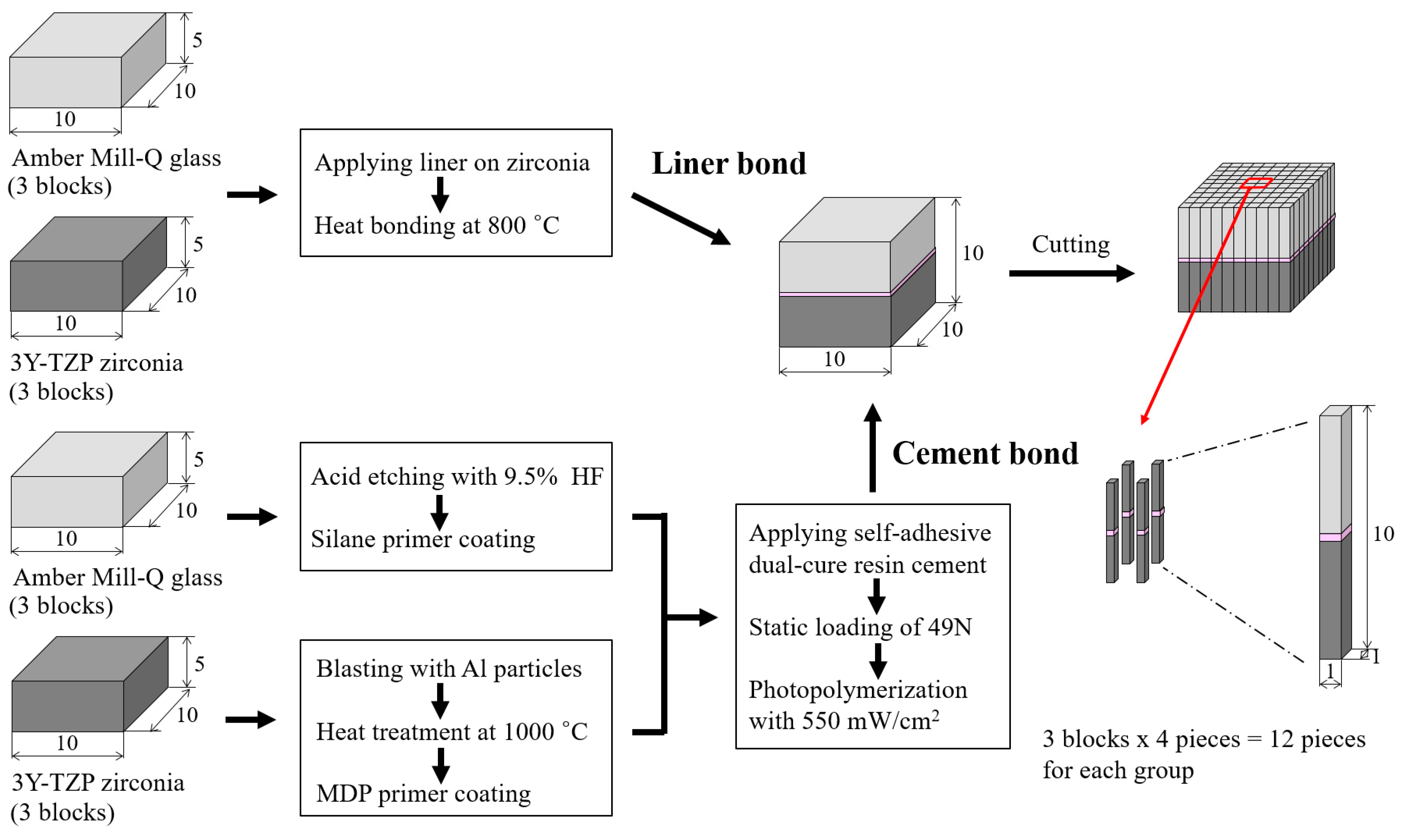
2.1.1. Preparation of Specimen
2.1.2. Microtensile Bond Strength Test
2.2. Fracture Test for Implant-Supported Crowns
2.2.1. Preparation of Implant-Supported Crowns
2.2.2. Fracture Test of Implant-Supported Crown
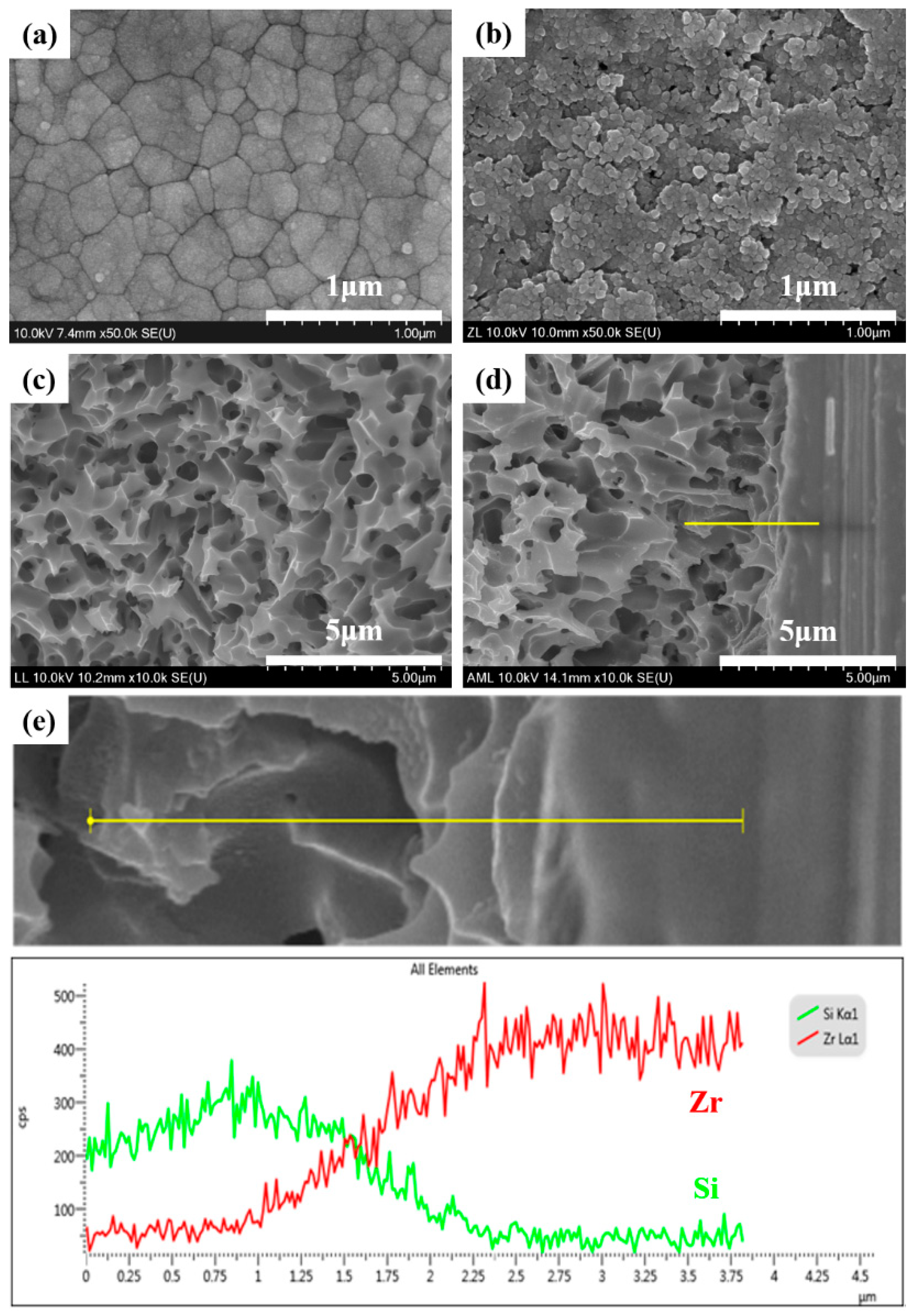
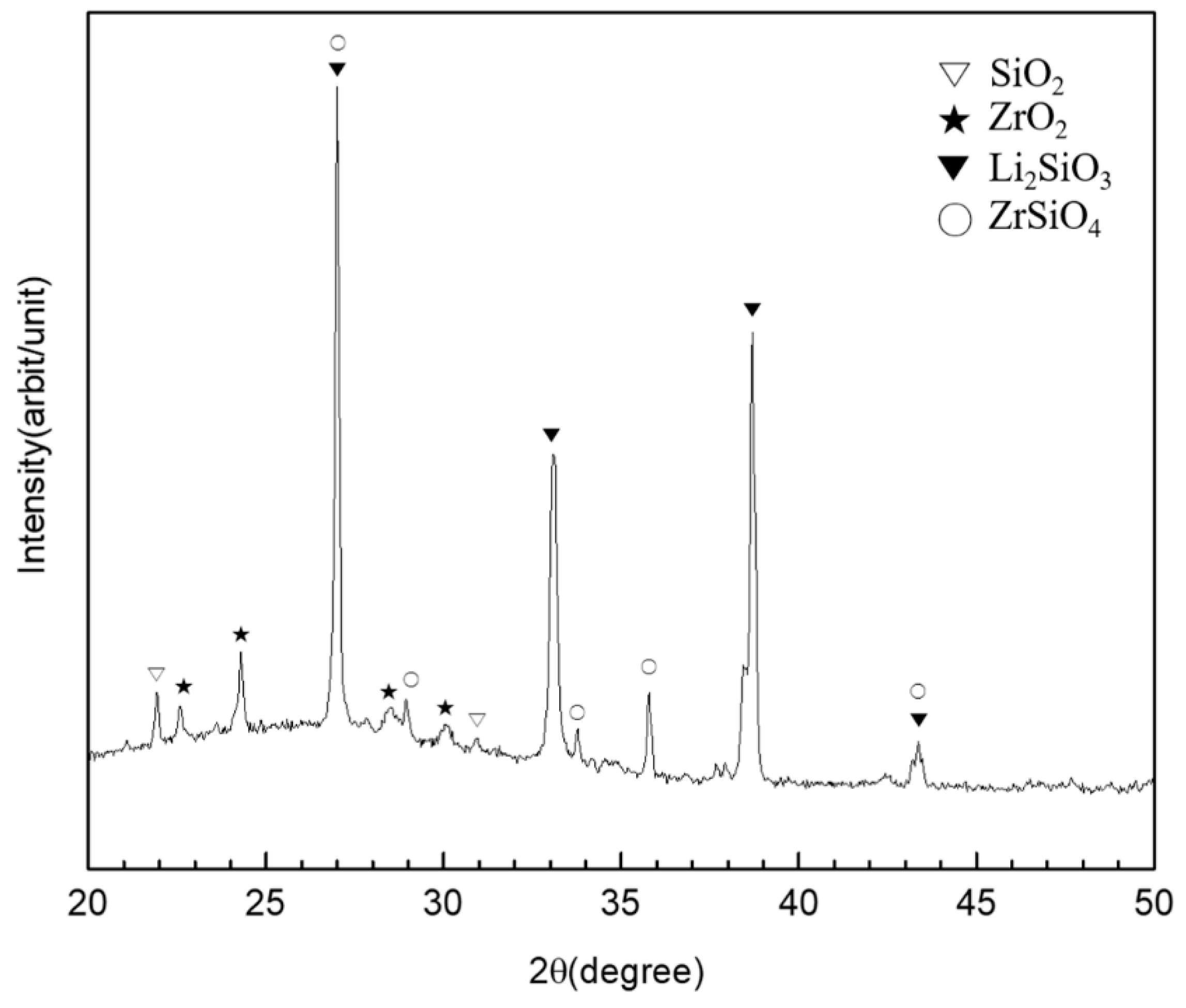
2.3. Surface Analysis
2.4. Statistical Analysis
3. Results
4. Discussion
5. Conclusions
Author Contributions
Funding
Acknowledgments
Conflicts of Interest
References
- Sailer, I.; Sailer, T.; Stawarczyk, B.; Jung, R.E.; Hämmerle, C.H.F. In vitro study of the influence of the type of connection on the fracture load of zirconia abutments with internal and external implant-abutment connections. Int. J. Oral Maxillofac. Implant. 2009, 24, 850–858. [Google Scholar]
- Wadhwani, C.; Piñeyro, A.; Avots, J. An Esthetic Solution to the Screw-Retained Implant Restoration: Introduction to the Implant Crown Adhesive Plug: Clinical Report. J. Esthet. Restor. Dent. 2011, 23, 138–143. [Google Scholar] [CrossRef] [PubMed]
- Wilson, T.G., Jr. The positive relationship between excess cement and peri-implant disease: A prospective clinical endoscopic study. J. Periodontol. 2009, 80, 1388–1392. [Google Scholar] [CrossRef] [PubMed]
- Sailer, I.; Zembic, A.; Jung, R.E.; Hämmerle, C.H.F.; Mattiola, A. Single-tooth implant reconstructions: Esthetic factors influencing the decision between titanium and zirconia abutments in anterior regions. Eur. J. Esthet. Dent. 2007, 2, 3. [Google Scholar]
- Zembic, A.; Sailer, I.; Jung, R.E.; Hämmerle, C.H.F. Randomized-controlled clinical trial of customized zirconia and titanium implant abutments for single-tooth implants in canine and posterior regions: 3-year results. Clin. Oral Implant. Res. 2009, 20, 802–808. [Google Scholar] [CrossRef] [PubMed]
- Nakamura, K.; Kanno, T.; Milleding, P.; Ortengren, U. Zirconia as a dental implant abutment material: A systematic review. Int. J. Prosthodont. 2010, 23, 4. [Google Scholar]
- Gehrke, P.; Johannson, D.; Fischer, C.; Stawarczyk, B.; Beuer, F. In vitro fatigue and fracture resistance of one- and two-piece CAD/CAM zirconia implant abutments. Int. J. Oral Maxillofac. Implant. 2015, 30, 546–554. [Google Scholar] [CrossRef]
- Kosmač, T.; Oblak, Č.; Marion, L. The effects of dental grinding and sandblasting on ageing and fatigue behavior of dental zirconia (Y-TZP) ceramics. J. Eur. Ceram. Soc. 2008, 28, 1085–1090. [Google Scholar] [CrossRef]
- Denry, I.; Kelly, J.R. State of the art of zirconia for dental applications. Dent. Mater. 2008, 24, 299–307. [Google Scholar] [CrossRef]
- Park, J.I.; Lee, Y.; Lee, J.H.; Kim, Y.L.; Bae, J.M.; Cho, H.W. Comparison of fracture resistance and fit accuracy of customized zirconia abutments with prefabricated zirconia abutments in internal hexagonal implants. Clin. Implant. Dent. Relat. Res. 2013, 15, 769–778. [Google Scholar] [CrossRef]
- Hamilton, A.; Judge, R.B.; E Palamara, J.; Evans, C. Evaluation of the fit of CAD/CAM abutments. Int. J. Prosthodont. 2013, 26, 370–380. [Google Scholar] [CrossRef] [PubMed]
- Martínez-Rus, F.; Ferreiroa, A.; Özcan, M.; Bartolomé, J.F.; Pradíes, G. Fracture resistance of crowns cemented on titanium and zirconia implant abutments: A comparison of monolithic versus manually veneered all-ceramic systems. Int. J. Oral Maxillofac. Implant. 2012, 27, 6. [Google Scholar]
- Klotz, M.W.; Taylor, T.D.; Goldberg, A.J. Wear at the titanium-zirconia implant-abutment interface: A pilot study. Int. J. Oral Maxillofac. Implant. 2011, 26, 970–975. [Google Scholar]
- Stimmelmayr, M.; Edelhoff, D.; Güth, J.-F.; Erdelt, K.; Happe, A.; Beuer, F. Wear at the titanium–titanium and the titanium–zirconia implant–abutment interface: A comparative in vitro study. Dent. Mater. 2012, 28, 1215–1220. [Google Scholar] [CrossRef] [PubMed]
- Foong, J.K.; Judge, R.B.; Palamara, J.E.; Swain, M.V. Fracture resistance of titanium and zirconia abutments: An in vitro study. J. Prosthet. Dent. 2013, 109, 304–312. [Google Scholar] [CrossRef]
- Elsayed, A.; Wille, S.; Al-Akhali, M.; Kern, M. Comparison of fracture strength and failure mode of different ceramic implant abutments. J. Prosthet. Dent. 2017, 117, 499–506. [Google Scholar] [CrossRef]
- Elsayed, A.; Wille, S.; Al-Akhali, M.; Kern, M. Effect of fatigue loading on the fracture strength and failure mode of lithium disilicate and zirconia implant abutments. Clin. Oral Implant. Res. 2018, 29, 20–27. [Google Scholar] [CrossRef]
- Gehrke, P.; Alius, J.; Fischer, C.; Erdelt, K.J.; Beuer, F. Retentive strength of two-piece CAD/CAM zirconia implant abutments. Clin. Implant. Dent. Relat. Res. 2014, 16, 920–925. [Google Scholar] [CrossRef]
- Truninger, T.C.; Stawarczyk, B.; Leutert, C.R.; Sailer, T.R.; Hämmerle, C.H.; Sailer, I. Bending moments of zirconia and titanium abutments with internal and external implant–abutment connections after aging and chewing simulation. Clin. Oral Implant. Res. 2012, 23, 12–18. [Google Scholar] [CrossRef]
- Hjerppe, J.; Lassila, L.V.J.; Rakkolainen, T.; Narhi, T.; Vallittu, P.K. Load-bearing capacity of custom-made versus prefabricated commercially available zirconia abutments. Int. J. Oral Maxillofac. Implant. 2011, 26, 1. [Google Scholar]
- Canullo, L. Clinical outcome study of customized zirconia abutments for single-implant restorations. Int. J. Prosthodont. 2007, 20, 5. [Google Scholar]
- Canullo, L.; Coelho, P.G.; Bonfante, E.A. Mechanical testing of thin-walled zirconia abutments. J. Appl. Oral Sci. 2013, 21, 20–24. [Google Scholar] [CrossRef][Green Version]
- Cheng, C.-W.; Yang, C.-C.; Yan, M. Bond strength of heat-pressed veneer ceramics to zirconia with various blasting conditions. J. Dent. Sci. 2018, 13, 301–310. [Google Scholar] [CrossRef]
- Yue, X.; Hou, X.; Gao, J.; Bao, P.; Shen, J. Effects of MDP-based primers on shear bond strength between resin cement and zirconia. Exp. Ther. Med. 2019, 17, 3564–3572. [Google Scholar] [CrossRef] [PubMed]
- Sato, T.; Anami, L.; Melo, R.; Valandro, L.; Bottino, M. Effects of Surface Treatments on the Bond Strength Between Resin Cement and a New Zirconia-reinforced Lithium Silicate Ceramic. Oper. Dent. 2016, 41, 284–292. [Google Scholar] [CrossRef]
- Mahmoodi, N.; Hooshmand, T.; Heidari, S.; Khoshro, K. Effect of sandblasting, silica coating, and laser treatment on the microtensile bond strength of a dental zirconia ceramic to resin cements. Lasers Med. Sci. 2016, 31, 205–211. [Google Scholar] [CrossRef]
- Yilmaz, B.; Gilbert, A.; Seidt, J.; McGlumphy, E.; Clelland, N. Displacement of Implant Abutments Following Initial and Repeated Torqueing. Int. J. Oral Maxillofac. Implant. 2015, 30, 1011–1018. [Google Scholar] [CrossRef] [PubMed]
- Schriwer, C.; Skjold, A.; Gjerdet, N.R.; Øilo, M. Monolithic zirconia dental crowns. Internal fit, margin quality, fracture mode and load at fracture. Dent. Mater. 2017, 33, 1012–1020. [Google Scholar] [CrossRef] [PubMed]
- Mores, R.T.; Borba, M.; Corazza, P.H.; Della Bona, Á.; Benetti, P. Influence of surface finishing on fracture load and failure mode of glass ceramic crowns. J. Prosthet. Dent. 2017, 118, 511–516. [Google Scholar] [CrossRef] [PubMed]
- Scribante, A.; Contreras-Bulnes, R.; Montasser, M.A.; Vallittu, P.K. Orthodontics: Bracket Materials, Adhesives Systems, and Their Bond Strength. BioMed Res. Int. 2016, 2016, 1–3. [Google Scholar] [CrossRef]
- Jang, Y.-S.; Noh, H.-R.; Lee, M.-H.; Lim, M.-J.; Bae, T.-S. Effect of Lithium Disilicate Reinforced Liner Treatment on Bond and Fracture Strengths of Bilayered Zirconia All-Ceramic Crown. Materials 2018, 11, 77. [Google Scholar] [CrossRef] [PubMed]
- Sawada, T.; Spintzyk, S.; Schille, C.; Zöldföldi, J.; Paterakis, A.; Schweizer, E.; Stephan, I.; Rupp, F.; Geis-Gerstorfer, J. Influence of Pre-Sintered Zirconia Surface Conditioning on Shear Bond Strength to Resin Cement. Materials 2016, 9, 518. [Google Scholar] [CrossRef] [PubMed]
- Spintzyk, S.; Yamaguchi, K.; Sawada, T.; Schille, C.; Schweizer, E.; Ozeki, M.; Geis-Gerstorfer, J. Influence of the Conditioning Method for Pre-Sintered Zirconia on the Shear Bond Strength of Bilayered Porcelain/Zirconia. Materials 2016, 9, 765. [Google Scholar] [CrossRef]
- Kern, M.; Wegner, S.M. Bonding to zirconia ceramic: Adhesion methods and their durability. Dent. Mater. 1998, 14, 64–71. [Google Scholar] [CrossRef]
- Blatz, M.B.; Chiche, G.; Holst, S.; Sadan, A. Influence of surface treatment and simulated aging on bond strengths of luting agents to zirconia. Quintessence Int. 2007, 38, 9. [Google Scholar]
- Ramos-Tonello, C.M.; Trevizo, B.F.; Rodrigues, R.F.; Magalhães, A.P.R.; Furuse, A.Y.; Lisboa-Filho, P.N.; Borges, A.F.S.; Tabata, A.S. Pre-sintered Y-TZP sandblasting: Effect on surface roughness, phase transformation, and Y-TZP/veneer bond strength. J. Appl. Oral Sci. 2017, 25, 666–673. [Google Scholar] [CrossRef] [PubMed]
- He, M.; Zhang, Z.; Zheng, D.; Ding, N.; Liu, Y. Effect of sandblasting on surface roughness of zirconia-based ceramics and shear bond strength of veneering porcelain. Dent. Mater. J. 2014, 33, 778–785. [Google Scholar] [CrossRef] [PubMed]
- Dérand, P.; Dérand, T. Bond strength of luting cements to zirconium oxide ceramics. Int. J. Prosthodont. 2000, 13, 131–135. [Google Scholar]
- Lüthy, H.; Loeffel, O.; Hammerle, C. Effect of thermocycling on bond strength of luting cements to zirconia ceramic. Dent. Mater. 2006, 22, 195–200. [Google Scholar] [CrossRef]
- Shin, Y.-J.; Shin, Y.; Yi, Y.-A.; Kim, J.; Lee, I.-B.; Cho, B.-H.; Son, H.-H.; Seo, D.-G. Evaluation of the shear bond strength of resin cement to Y-TZP ceramic after different surface treatments. Scanning 2014, 36, 479–486. [Google Scholar] [CrossRef]
- Baldassarri, M.; Hjerppe, J.; Romeo, D.; Fickl, S.; Thompson, V.P.; Stappert, C.F.J. Marginal accuracy of three implant-ceramic abutment configurations. Int. J. Oral Maxillofac. Implant. 2012, 27, 3. [Google Scholar]
- Smith, N.A.; Turkyilmaz, I. Evaluation of the sealing capability of implants to titanium and zirconia abutments against Porphyromonas gingivalis, Prevotella intermedia, and Fusobacterium nucleatum under different screw torque values. J. Prosthet. Dent. 2014, 112, 561–567. [Google Scholar] [CrossRef] [PubMed]
- Han, J.; Zhao, J.; Shen, Z. Zirconia ceramics in metal-free implant dentistry. Adv. Appl. Ceram. 2017, 116, 138–150. [Google Scholar] [CrossRef]
- Att, W.; Kurun, S.; Gerds, T.; Strub, J.R. Fracture resistance of single-tooth implant-supported all-ceramic restorations: An in vitro study. J. Prosthet. Dent. 2006, 95, 111–116. [Google Scholar] [CrossRef] [PubMed]
- Von Maltzahn, N.F.; Holstermann, J.; Kohorst, P. Retention Forces between Titanium and Zirconia Components of Two-Part Implant Abutments with Different Techniques of Surface Modification. Clin. Implant. Dent. Relat. Res. 2016, 18, 735–744. [Google Scholar] [CrossRef] [PubMed]
- Ebert, A.; Hedderich, J.; Kern, M. Retention of zirconia ceramic copings bonded to titanium abutments. Int. J. Oral Maxillofac. Implant. 2007, 22, 921–927. [Google Scholar]
- Proeschel, P.; Morneburg, T. Task-dependence of Activity/Bite-force Relations and its Impact on Estimation of Chewing Force from EMG. J. Dent. Res. 2002, 81, 464–468. [Google Scholar] [CrossRef] [PubMed]
- Andersson, B.; Taylor, Å.; Lang, B.R.; Scheller, H.; Schärer, P.; Sorensen, J.A.; Tarnow, D. Alumina ceramic implant abutments used for single-tooth replacement: A prospective 1-to 3-year multicenter study. Int. J. Prosthodont. 2001, 14, 432–438. [Google Scholar] [PubMed]
- Liu, D.; Matinlinna, J.P.; Pow, E.H. Insights into porcelain to zirconia bonding. J. Adhes. Sci. Technol. 2012, 26, 1249–1265. [Google Scholar]
- Fischer, J.; Grohmann, P.; Stawarczyk, B. Effect of zirconia surface treatments on the shear strength of zirconia/veneering ceramic composites. Dent. Mater. J. 2008, 27, 448–454. [Google Scholar] [CrossRef] [PubMed]
- Aboushelib, M.N.; Kleverlaan, C.J.; Feilzer, A.J. Selective infiltration-etching technique for a strong and durable bond of resin cements to zirconia-based materials. J. Prosthet. Dent. 2007, 98, 379–388. [Google Scholar] [CrossRef]


| Group | Liner-Bonded | Resin Cement-Bonded | |
|---|---|---|---|
| Parameter | |||
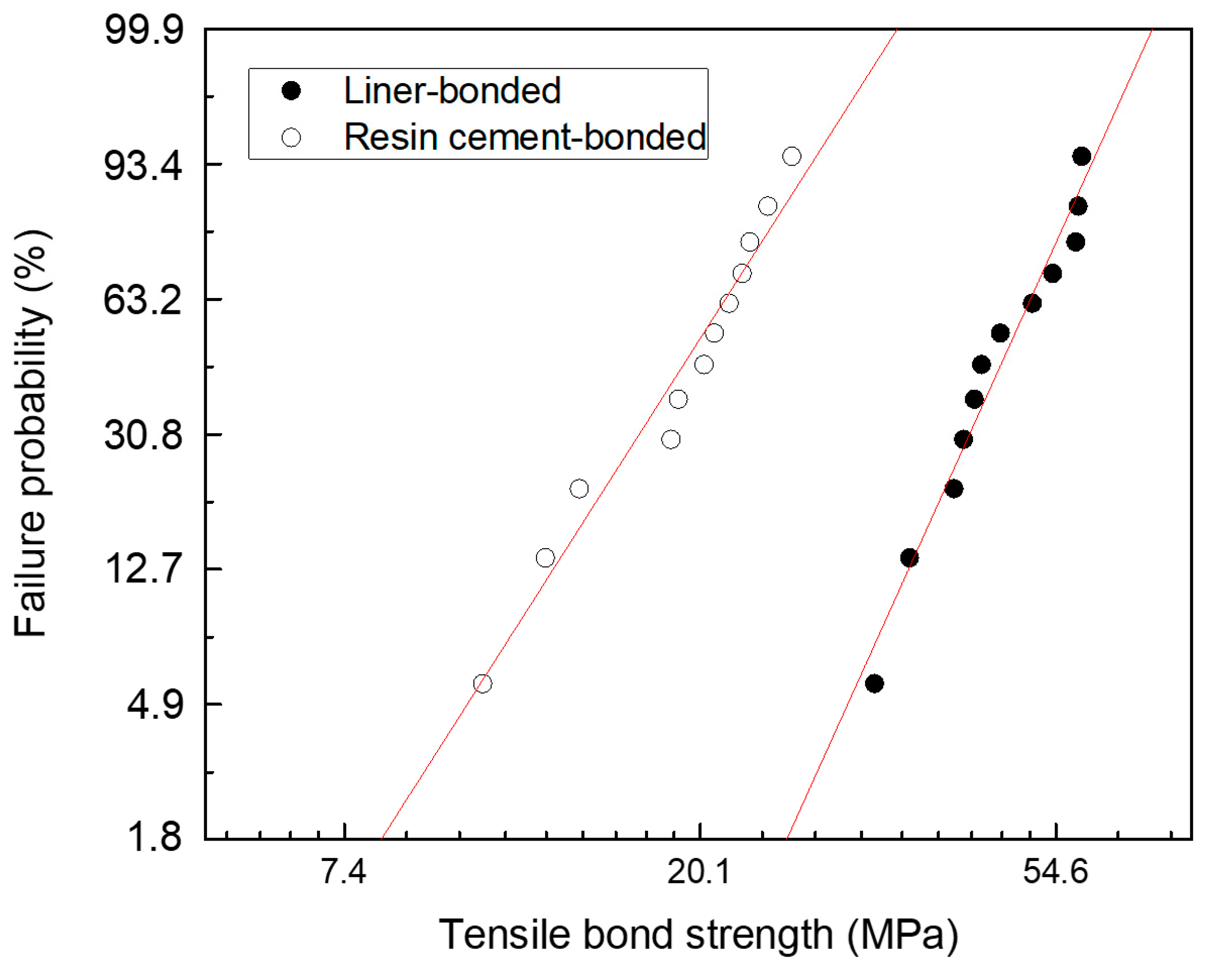
| m | 5.836 | 4.133 | |
| σo | 50.8 | 2.36 | |
| r2 | 0.961 | 0.958 | |
| σf(mean) ± SD | 47.7 ± 8.7 | 19.6 ± 4.7 | |
| σf(min/med/max) | 32.8/45.5/58.7 | 10.9/20.6/26.0 | |
| N | 12 | 12 | |
© 2019 by the authors. Licensee MDPI, Basel, Switzerland. This article is an open access article distributed under the terms and conditions of the Creative Commons Attribution (CC BY) license (http://creativecommons.org/licenses/by/4.0/).
Share and Cite
Jang, Y.-S.; Oh, S.-H.; Oh, W.-S.; Lee, M.-H.; Lee, J.-J.; Bae, T.-S. Effects of Liner-Bonding of Implant-Supported Glass–Ceramic Crown to Zirconia Abutment on Bond Strength and Fracture Resistance. Materials 2019, 12, 2798. https://doi.org/10.3390/ma12172798
Jang Y-S, Oh S-H, Oh W-S, Lee M-H, Lee J-J, Bae T-S. Effects of Liner-Bonding of Implant-Supported Glass–Ceramic Crown to Zirconia Abutment on Bond Strength and Fracture Resistance. Materials. 2019; 12(17):2798. https://doi.org/10.3390/ma12172798
Chicago/Turabian StyleJang, Yong-Seok, Sang-Hoon Oh, Won-Suck Oh, Min-Ho Lee, Jung-Jin Lee, and Tae-Sung Bae. 2019. "Effects of Liner-Bonding of Implant-Supported Glass–Ceramic Crown to Zirconia Abutment on Bond Strength and Fracture Resistance" Materials 12, no. 17: 2798. https://doi.org/10.3390/ma12172798
APA StyleJang, Y.-S., Oh, S.-H., Oh, W.-S., Lee, M.-H., Lee, J.-J., & Bae, T.-S. (2019). Effects of Liner-Bonding of Implant-Supported Glass–Ceramic Crown to Zirconia Abutment on Bond Strength and Fracture Resistance. Materials, 12(17), 2798. https://doi.org/10.3390/ma12172798