1. Introduction
With the development of urbanization and the rapid progress of civil engineering, the problem of urban congestion has become increasingly prominent. Therefore, it is necessary to improve the construction of urban transportation infrastructure methods and expand urban expressway networks. In order to build, replace, and repair a bridge, or a series of bridges, in areas with heavy traffic, traditional construction methods are usually used in current engineering projects. These methods generally include field activities, such as the installation of supports, formwork, binding of reinforcement bars, pouring and curing of concrete, etc. These onsite construction activities not only consume a great deal of time but also lead to traffic congestion, which weakens the safety and efficiency of the traffic network. On the other hand, due to the constraints of the construction site and climatic conditions, the components of onsite construction are prone to quality problems, which may potentially affect the durability of the structure. Accelerated bridge construction (ABC) is a promising approach to reduce the impact of construction on traffic, improve the quality of materials and durability of products, and minimize the construction time [
1,
2,
3].
A combination of steel beams and a concrete deck with shear connectors, known as steel-concrete composite beams, are widely used in the ABC approach. Due to the use of shear stud tied together in the upper part of steel beam, this type of structure can give full strength to the respective properties of the two materials, especially for short and medium-span urban areas and highways [
4,
5,
6,
7]. The headed stud shear connectors are usually used to resist longitudinal slip and vertical separation between the steel beam and concrete slab. In general practice, construction of steel-concrete composite girder bridge, I-shaped steel beams, or a small steel box girder flange of the steel beam structure are used [
8,
9]. Compared with I-shaped steel girder, the small box section has better stability and torsional resistance. Moreover, compared with large box girders, small box girders have a flexible cross-section, lightweight, easy fabrication, and assembly, and thus, are more suitable for accelerated construction of the bridges [
10].
The characteristics of concrete play a vital role in all kinds of structure for overall strength. Concrete is brittle and has partial ductile behavior. Therefore, a different form of reinforcement is needed to boost structural stability. Steel bars are used as reinforcement in concrete structures; however, there’s still a chance of crack, deflection and slip formation, which causes a big problem within the overall stability of the structure [
11,
12,
13,
14,
15,
16,
17].
Concrete is a comparatively widely used material. However, it will run into huge issues and defects if it’s not prepared correctly. The defects are started from the concrete parts of reinforcement concrete members and extended until encountering a reinforcing bar in which yield to significant problems. We must control these defects to prolong the life period of concrete structures. Hence, according to the application of the concrete in the structure, a multi-directional and closely spaced reinforcement may need to be utilized. The use of fibers is another solution to enhance the ductility of concrete material. Fiber-reinforced concrete (FRC) consists of short distinct fibers that are uniformly distributed and at random bound among the concrete matrix. The fibers are mostly classified into four categories, namely—steel fiber, glass fiber, natural fiber, and synthetic fiber, all of which have their own respective properties [
18,
19,
20,
21,
22].
The use of fibers in concrete components causes the increase of structural integrity, provides high tensile strength to plain concrete, decreases the permeableness of concrete, and increases the resistance to impact load. Fibers reduce the number of rebars without affecting the strength. It will additionally eliminate the defects by bridging action. Flexural behavior, bond strength, and particularly toughness of SFRC (steel fiber reinforced concrete) increases by increasing fiber content. Carbon or steel fibers are added to a cement matrix at a high volume fraction (0.5%–3%) to extend the conduction of the composite. The properties of fiber concrete depend on the quantity of fibers used [
23,
24,
25,
26,
27,
28].
Various problems are occurred in composite materials in terms of slip deflection and crack. The crack in a composite structure could decrease the stiffness and strength, which may accelerate the failure of the structure. Due to the inherent material properties of fiber concrete, the presence of fiber improves the resistance of conventionally reinforced structural members to serviceability deflection condition. Although the slip is not the main reason for a structural failure, it is part of the failure process due to losses in the structural integrity. Therefore, controlling slip plays an essential role in the failure mechanism of steel-concrete composite structures [
29,
30,
31,
32,
33,
34,
35].
Generally, the concrete grade is below C50 in traditional construction, while high-performance concrete with a grade higher than C60 is used in the ABC process. Therefore, due to the high mechanical strength and durability, high-performance concrete in the composite beam receives much attention [
36]. In the steel-concrete composite beams, there is a sliding problem in the interface layer between two materials, which is usually appeared by increasing load intensity. It can increase damping, which is beneficial for dynamic loading conditions [
37,
38]. The existence of such an interface slip can reduce the stiffness, increase the curvature and the deformation of composite beams [
39,
40,
41,
42,
43,
44,
45]. Therefore, the actual working condition of composite beams cannot be precisely determined without considering the interface slip effect. In the past few years, many studies attempted to address the slip problem; however, few of them, if any, considered the group studs in the beam [
46,
47,
48,
49,
50,
51,
52]. So, this research is only focused on the slip tests of a steel-concrete composite small box girder (SCCSBG) in the simply supported and continuous beams.
In this research, two equations were proposed, one for the simply supported beam and another for continuous beams to consider the influence of group studs and compare their performance. For this purpose, three simply supported SCCSBG (steel-concrete composite small box girder), and two continuous SCCSBG were experimentally tested under the action of the vertically applied load. The slip values were observed throughout the full span of the beam. The details of the experiments and their behavior are discussed in the following sections.
2. Design and Fabrication of Experimental Beams
The experimental SCCSBG beams, which were made using accelerated construction techniques, consist of an open steel box girder, diaphragm, welded stud, and concrete slab. Due to difficulties in the process of making a real-size scale model, especially in the case of the concrete bridge deck and the thickness of the steel plate, it followed the design specification. Based on the 25 m span prototype bridge, a stereotype model of steel concrete steel fibrous small box girder was prepared to the actual length ratio of 1:4 and 1:6 for continuous and simply supported beams, respectively. The ECB-1 and ECB-2 were used for the continuous beam, whereas SPB1 to SPB3 were used for the simply supported beam. The material details about both types of the beams are listed in
Table 1.
In the accelerated construction of SCCSBG, the spacing of studs, group arrangement of studs, and concrete materials are the three main factors. Using the high-performance concrete reduces the structural weight and cost and increases the durability. Therefore, recently, it is more widely used in bridge engineering. The spacing and arrangement of the studs should be determined using the degree of shear connection. The degree of shear connection is the ratio of the number of actual welded studs in the shear span to the number of welded studs required for the complete shear connection. In the designing procedures, while considering an arrangement for studs, a minimum space according to the degree of shear connection is defined to ensure the mechanical performance of the structure. However, in term of construction, having more space between the group studs is preferred. To design the test beams, the degree of the shear connection was determined based on the designing of steel and concrete composite bridges code GB50917-2013 [
53]. However, there is no code available to specify the arrangement and spacing of group studs. Therefore, the formula of bearing capacity for a single stud defined in this code is used here. EC4 [
54] requires that the maximum spacing of stud uniformly distributed along the steel-concrete composite beams should not exceed four times of the concrete slab thickness or the value of 800 mm.
Based on the steel structure design code GB50017-2017 [
55], if the strength and deformation are satisfied, the longitudinal shear capacity of the shear connectors at the interface of composite beams guarantees the full flexural capacity of the beam. Hence, the beam can be designed according to the partial shear connection. However, the partial shear connection is limited to the composite beams with equal cross-section and the spans less than 20 m. The American Association of State Highway and Transportation Officials (AASHTO) [
56] bridge design code stipulates that the spacing of reserved holes is not more than 610 mm.
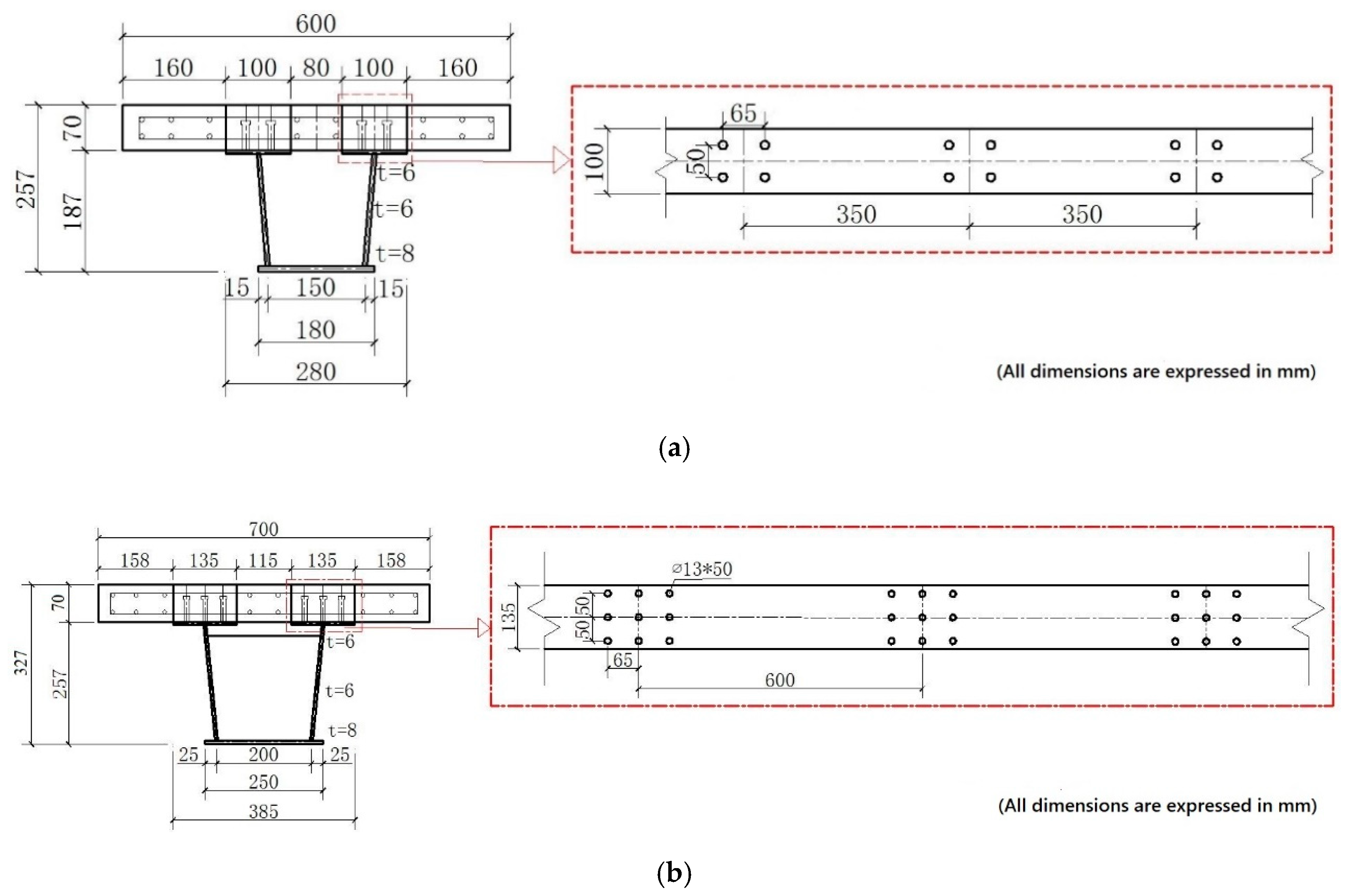
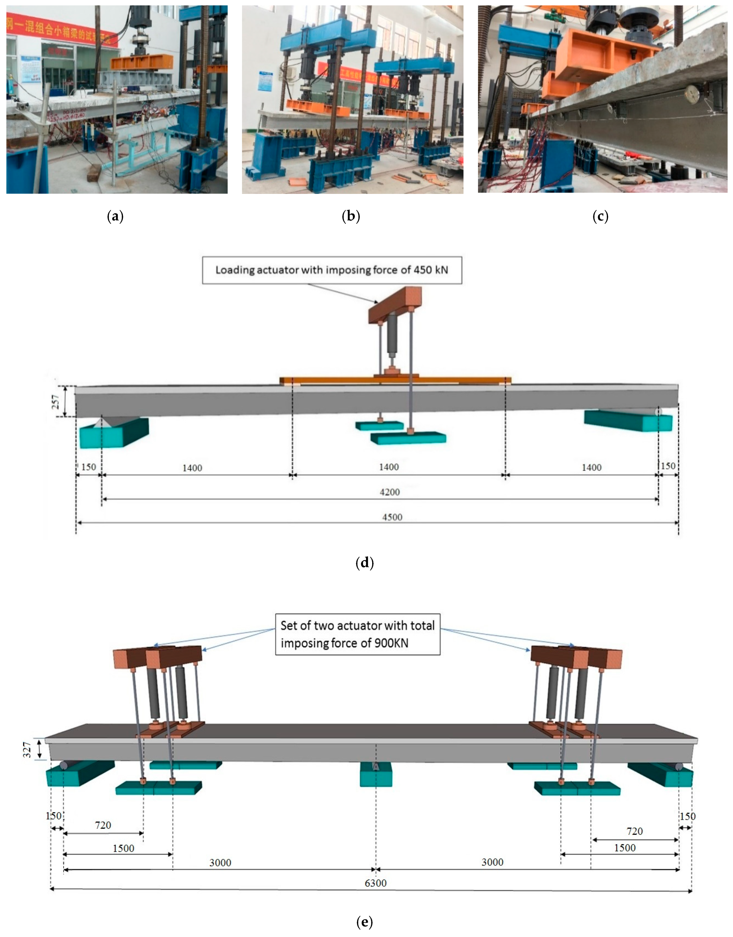
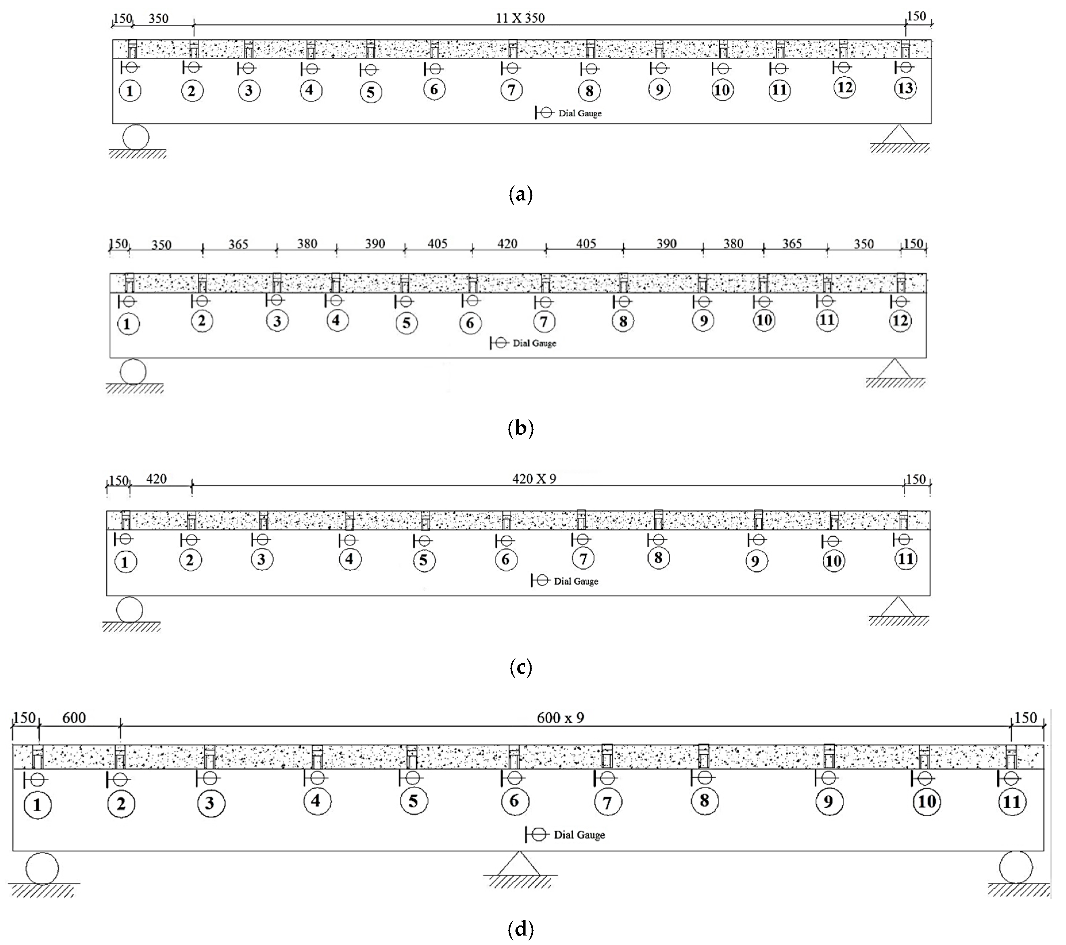
In the fabrication, two different lengths of girders are used to manufacture the beams. The smaller one is used in the SPBs, and the larger one is used in the ECBs. The SPBs are 4.5 m in length, 4.2 m in support spacing, 258 mm in depth of the composite beam and 70 mm in the thickness of the precast concrete slab. For the steel U-type girder, the depth is 0.187 m, the top width is 180 mm, and the bottom width is 150 mm. The upper flange is 6 mm thick and 100 mm wide. The web is 6 mm thick, and the bottom is 8 mm thick. A solid web diaphragm is set every 700 mm from support. The diaphragm is 6 mm thick and 160 mm high. The steel U-type girder is made of Q345qc steel. The group studs are welded to the upper flange of the steel beam. The dimension and materials of welding for studs are 13 mm × 45 mm and ML15AL, respectively. The SPBs were made of C60 high-performance concrete with a width of 600 mm and a thickness of 70 mm. The center distance of the group studs varies from 350 mm to 420 mm from support to midspan. Two layers of steel bars were arranged longitudinally. The upper layer of steel bars is HRB400 with a diameter of 10 mm, and the lower layer of steel bars and stirrups are HPB300 with a diameter of 8 mm. The spacing of stirrups is 60 mm, and no stirrups are arranged in the reserved hole position. The details about stud arrangement and cross-section of the SPBs is shown in
Figure 1a. The design parameters of SPBs and ECBs are presented in
Table 2.
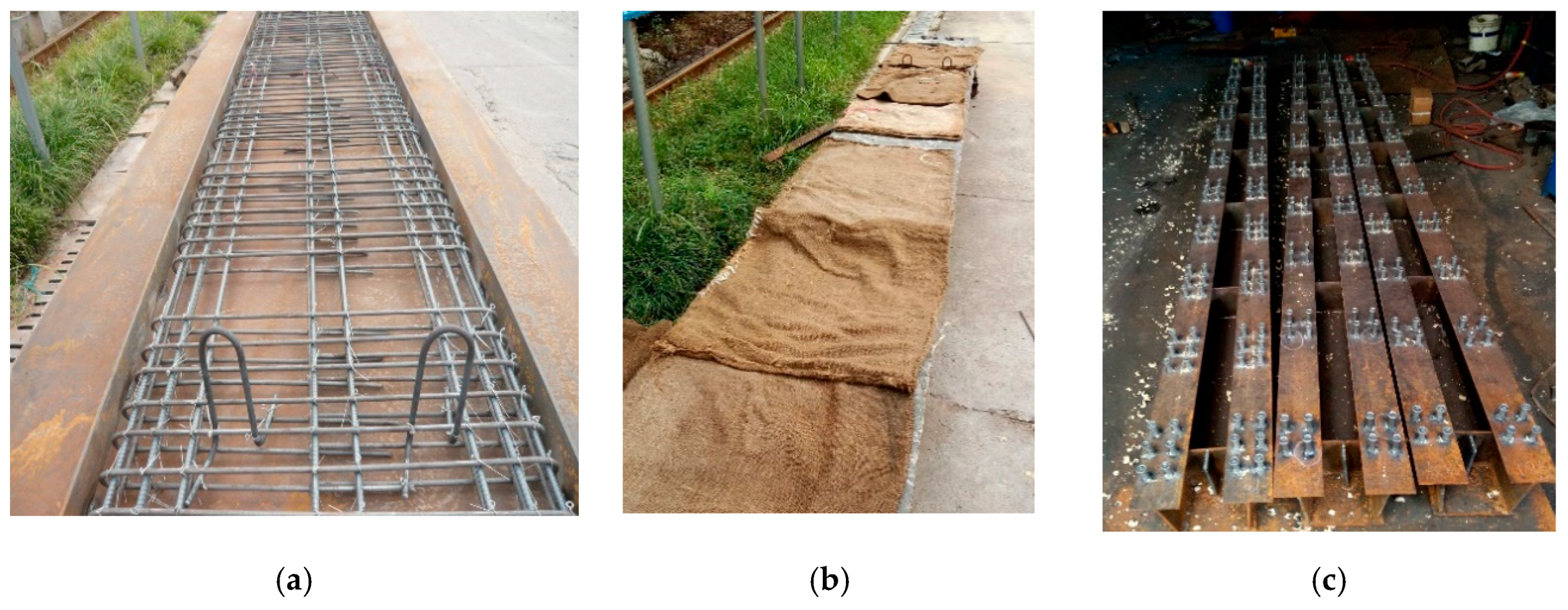
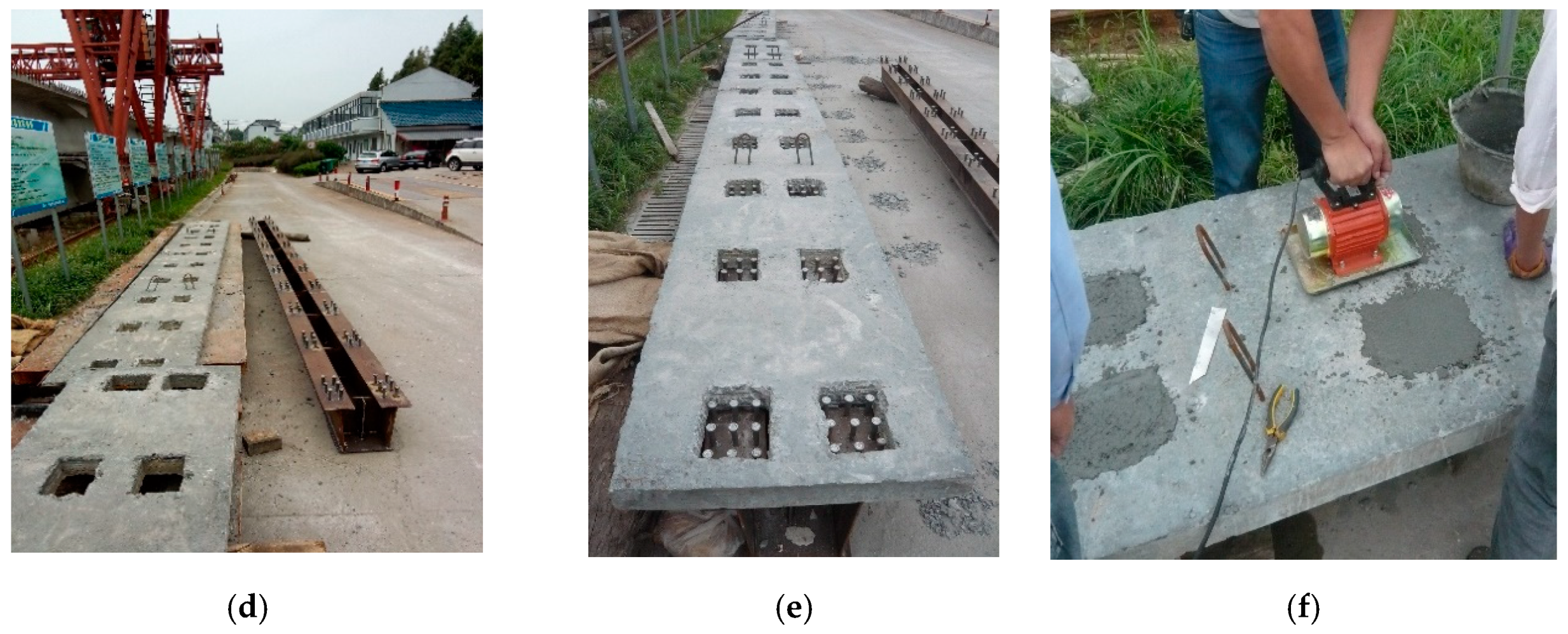
ECBs were made of two spans, each span is 3 m in length, with a total length of 6.3 m long. The total depth of the composite box girder was 327 mm with 70 mm slab thickness and 257 mm depth of steel U-type girders. The upper flange was 6 mm thick and 135 mm wide. The essential of the web was 6 mm, whereas the bottom plate was 8 mm. The diaphragm was set to every 600 mm from support to throughout the box girder. The thickness and height of the diaphragm were 6 mm and 220 mm, respectively. The construction of prefabricated concrete slabs, welding steel beams, and welding studs was in accordance with the requirements of design drawings and technical construction specifications. The C60 high-performance concrete and C80 steel fiber high-performance concrete are used for prefabricated slab and reserved hole filling, respectively. The detail configuration of both types of box girder is shown in
Figure 1, and the main fabrication process is shown in
Figure 2.
For the high-performance concrete element, copper-plated steel fiber with a diameter of 0.2 mm and length of 13 mm, tensile strength of 2000 MPa, and a volume fraction of 1.5% was used. The details about the physical properties of the steel fiber are listed in
Table 3. The obtained physical properties by the use of cement, fine aggregate, coarse aggregate, water, and chemicals are based on different codes [
57,
58,
59]. The information about different of properties and materials uses are described in
Appendix A. The arrangement of bars in the ECB’s are the same as SPB’s. However, for the stud arrangement, the hole with a plane size of 160 mm × 100 mm is reserved and filled with C80 steel fiber concrete. The size of the ECB’s welding stud is 13 mm × 50 mm.
4. Simplified Model
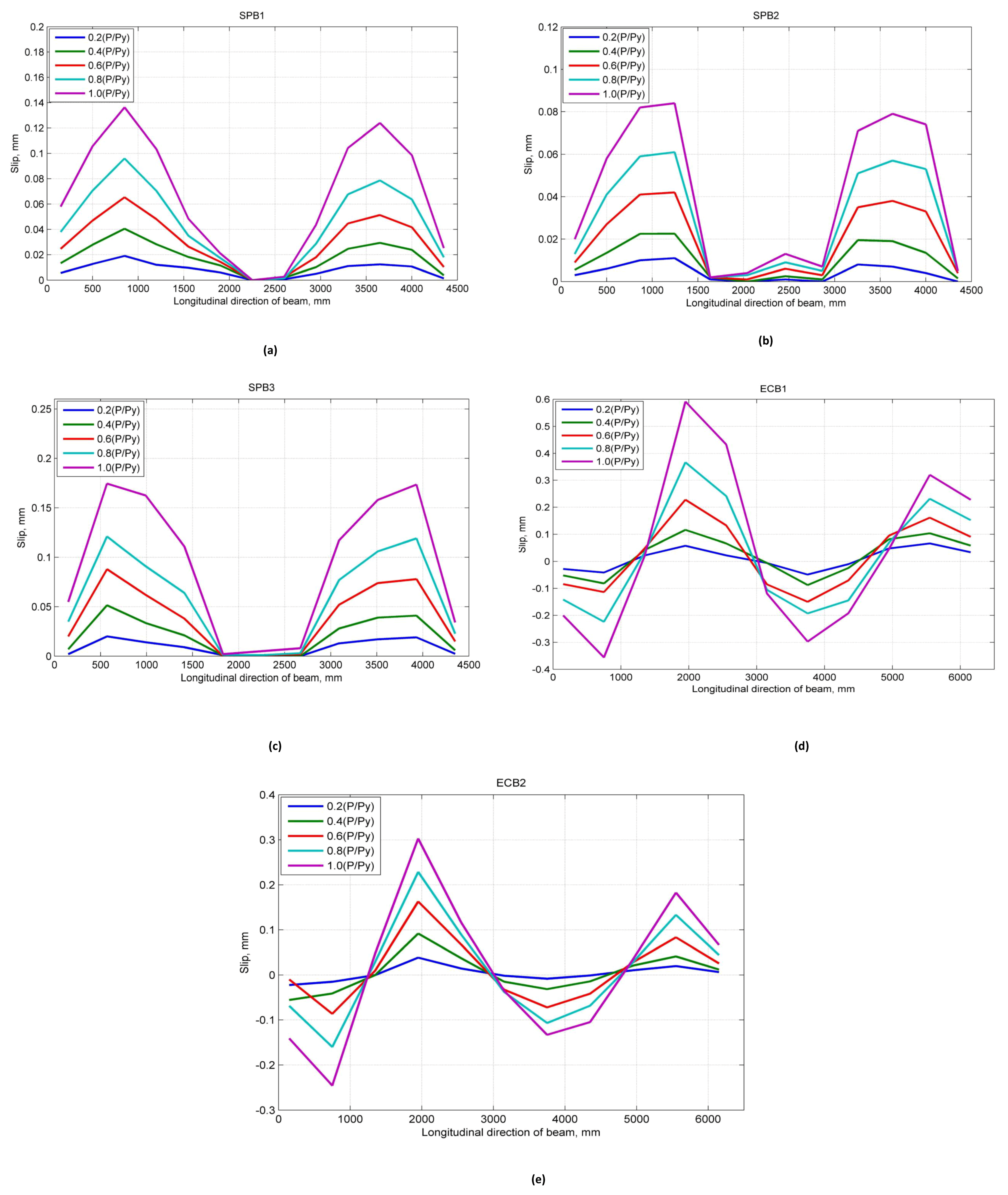
The slip was observed under 24 kN of load where the values of SPB1, SPB2, and SPB3 were 0.009, 0.004 and 0.008 mm, respectively. The slip values of the SPBs increases with the increase of the load. As shown in
Figure 5, the relationship between the growth rate of the SPBs slip values are SPB3> SPB1 > SPB2, and it does not increase linearly with the increase of the load. The inconsistency growth rates of slip values are mainly affected by the degree of shear connection. Therefore, as the load increases, the welding studs gradually entered into yielding. So, the growth rate of slip values increases continuously, and the slip value of each stud group in the shear span tends to be uniform.
The maximum slip values of SPB1, SPB2, and SPB3 under 270 kN load are 0.136, 0.084, and 0.170 mm, respectively. The maximum slip values have an inverse relationship with the degree of shear connection. The larger the degree of shear connection, the smaller the slip value. The main reason for this is the local effect of group studs shear connectors. The location of reserved holes is being centralized, and the shear stiffness of this location is becoming more significant than the traditional uniformly distributed studs.
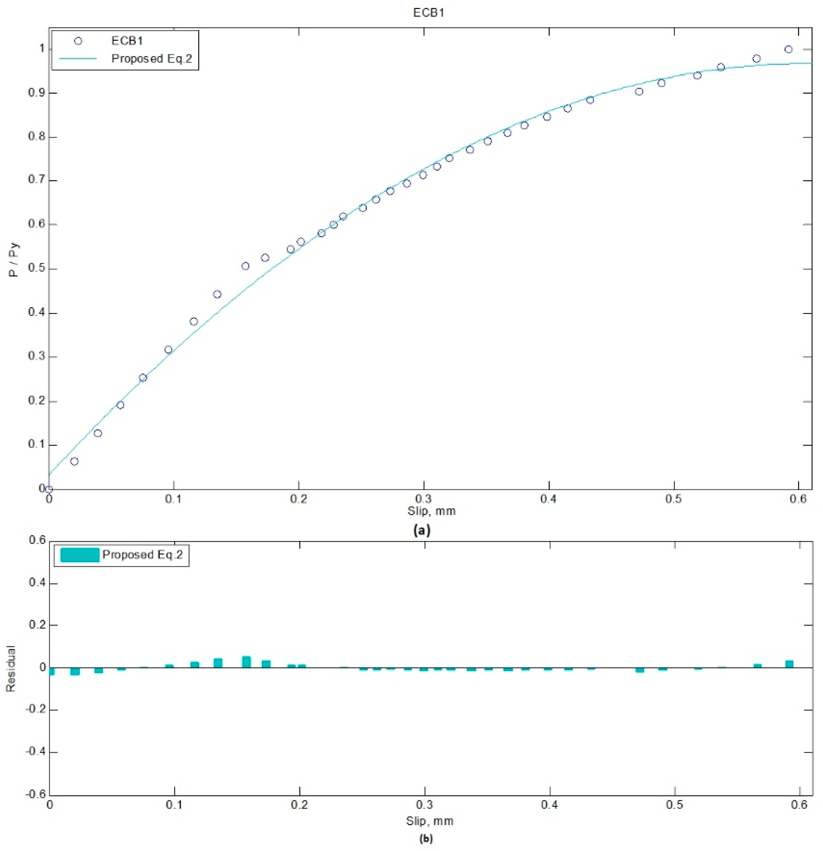
There are so many conditions which need an ideal mathematical solution to represent a set of data. Using the N-order polynomial regression model, a line can be fitted to the experimental scatter data, and formula can be extracted to represent/estimate the data [
60]. Therefore, two quadratic equations extracted using N-order polynomial regression are proposed in the form of Equations (1) and (2). The residual value for each data point is the distance from the target point to the regression line, which is error in prediction. The norm of residual is a measure of goodness of fit, so that a value centered around zero indicates a better fit [
61]. Equation (1) is for SPBs, while Equation (2) addresses ECBs. The norm of residuals for Equations (1) and (2) are 0.027 and 0.112, respectively.
where P/Py is the ratio of an applied load to yield load, and s is the slip of the beam at corresponding load. The proposed equation can be used for the prediction of the slip in SCCSBG of simply supported and continuous beam with fully composite action. When the degree of shear connection is equal, these equations can predict the slip value of that beam. Whereas, with a different degree of shear connection, it can relate the change in slip values between them. However, the limitation of the proposed equation regarding the dimension and construction size should also be considered while applying it.
Figure 6 and
Figure 7 show the proposed equations with the experimental data and corresponding residual values. The residual (%) in the fitting process of SPB3 and ECB1 load-slip curves are presented in
Table 4 and
Table 5, respectively.
6. Conclusions
This study focused on the static behavior of the accelerated construction steel fibrous high-performance steel-concrete composite small box girder bridge. To achieve this, two different types of simply supported and continuous beams have been tested with trapezoidal steel beams and different shear stud arrangements. Each sample was tested under a progressive applied vertical loading, and the maximum slip was recorded at key points along the span for both simply supported and continuous beams. Using the dataset obtained from laboratory tests, simplified empirical relationships were developed to approximate the slip of both simply supported and continuous beams with a different degree of shear connections.
The following main conclusions are drawn according to investigation in this paper.
It was observed that the measured slip values for SPB1, SPB2, and SPB3 samples of simply supported beams at 0.2 (P/Py) were 0.019 mm, 0.011 mm, and 0.020 mm, respectively. While the slip values for ECB-1 and ECB-2 samples of continuous beams were 0.057 mm and 0.038 mm, respectively.
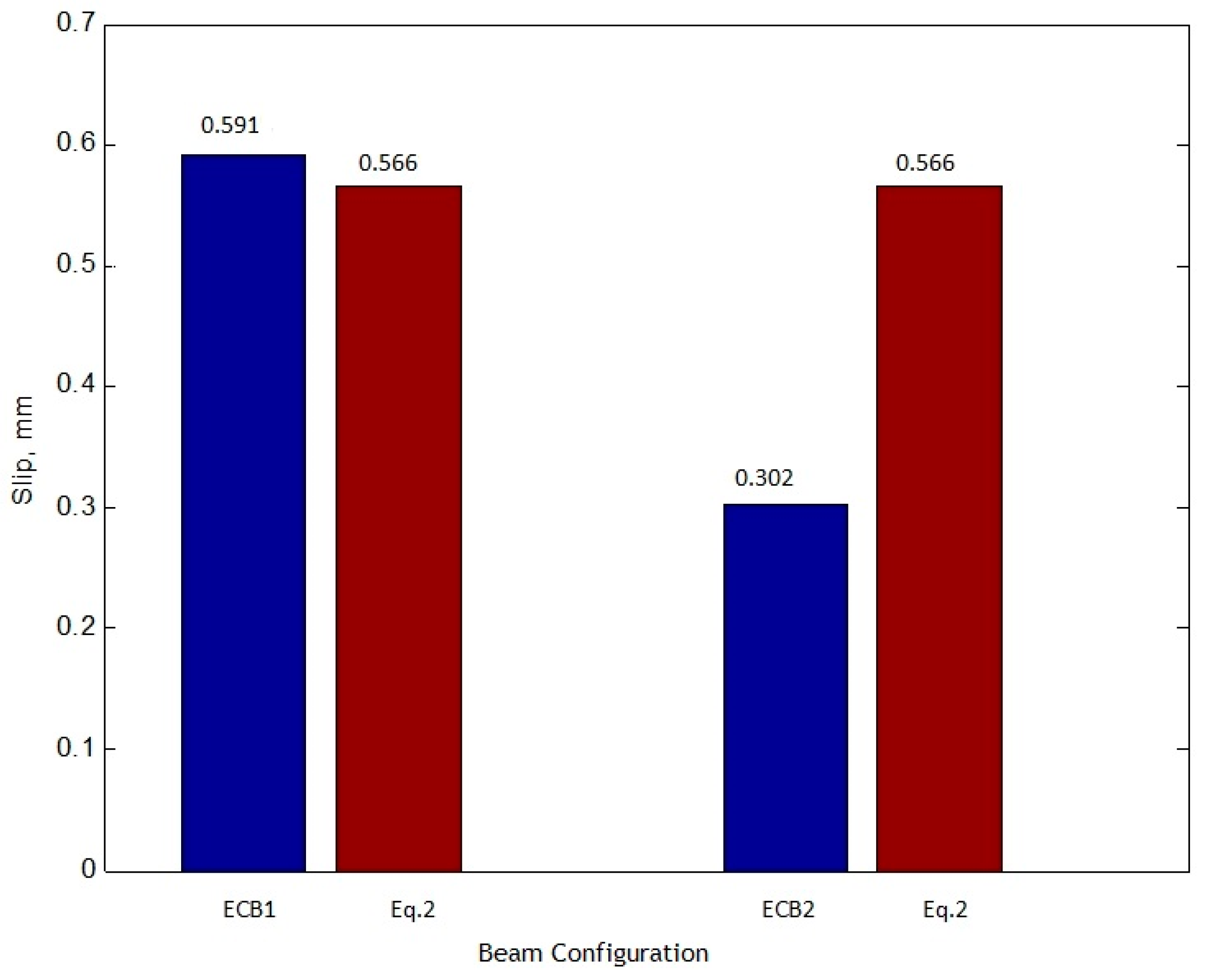
The integrity and load-carrying capacity of accelerated construction high-performance SCCSBG are found to be more than traditional construction because of the use of steel fibers in concrete. Therefore, for SPB1, SPB2 and SPB3, the slip values of simply supported beams at 1.0 (P/Py) are bounded to 0.136 mm, 0.084 mm and 0.174 mm, respectively. In addition, for continuous beams, the sliding values measured by ECB-1 and ECB-2 at 1.0 (P/Py) are limited to 0.591 mm and 0.303 mm, respectively.
Because of the higher degree of shear connection, the slip of SPB3 is 1.247 times more than SPB1, and 2.023 times more than SPB2. Also, the slip value of ECB1 is 1.952 times greater than ECB2. That is, the higher the degree of shear connection is, the smaller the maximum slip value becomes.
Since the proposed equations are presented in an explicit form, they can be practically used to predict the slip of group studs in either simply supported or continuous beam. As the experimental model was designed with ratios of 1:6 and 1:4 for simply supported and continuous beams, respectively, the application of the proposed model is limited to cases with a similar range of parameters. Other sizes and forms of accelerated construction beams can be investigated by the authors in future research.


