Wire Ropes and CFRP Strips to Provide Masonry Walls with Out-Of-Plane Strengthening


Abstract
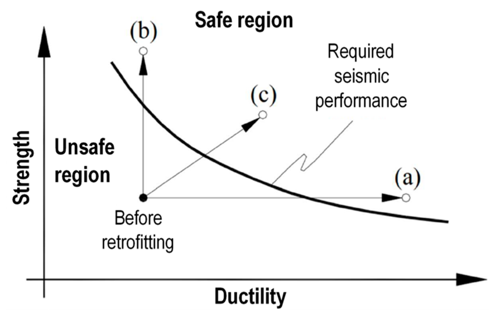
1. Introduction
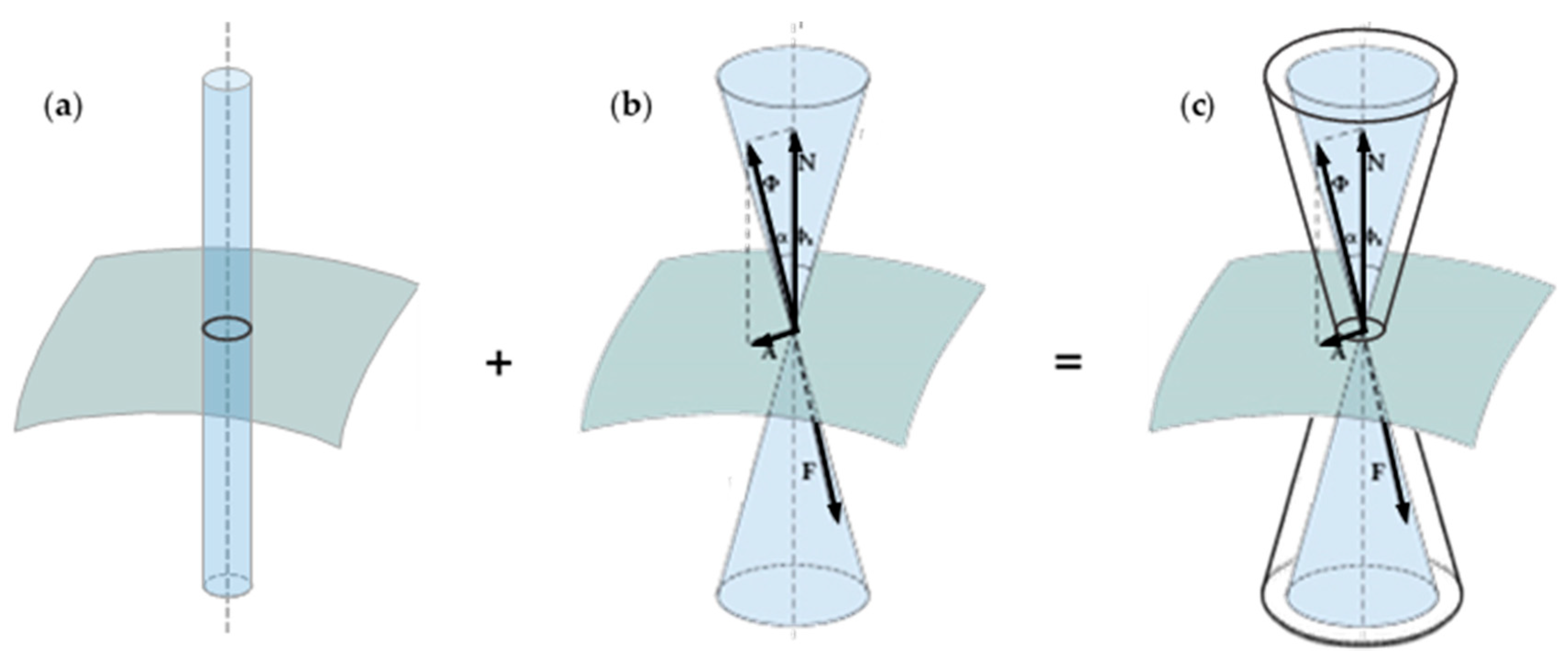
- N is the normal force that develops as a reaction to the weight force P, exerted by the body at rest in Figure 2 (body 1): N is equal and opposite to P;
- A is the frictional force that develops as a reaction to the shear force T, exerted by the hanging body in Figure 2 (body 2): A is equal and opposite to T as long as body 1 is at rest;
- Φ is the resultant of the active forces, N and A, and is applied to body 1;
- F is the resultant of the reactive forces, P and T, and is applied to the support plane.
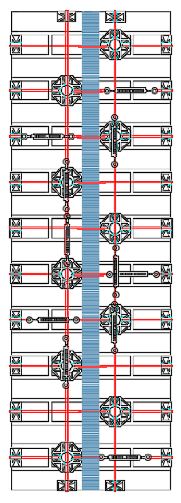
2. The Straps/Strips Combined Technique
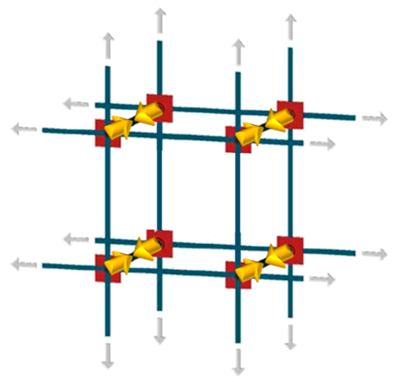
- It consists of a three-dimensional continuous strengthening system that leads to a box-type behavior of the retrofitted building (Figure 6).
- It establishes good transversal connections, which are particularly useful in cases of multi-layer masonry walls with weak connections between the vertical layers.
- It allows the straps to form closed loops that cross the thickness of the masonry wall.
- It is an active reinforcement technique, since the fastening system provides a pre-tension to the straps. Thanks to the pre-tension, the straps do not require any damage to begin to post-compress the masonry enclosed within them.
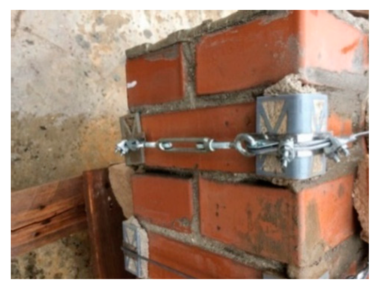
- It makes use of special protective elements at the loop corners, to avoid damage due to concentration of stresses at the corners.
- It is easily concealable under a plaster layer because the thicknesses of the straps and the protective elements are of the same order of magnitude as the thickness of the plaster. Therefore, from an aesthetic point of view it is minimally invasive.
- It overcomes the irregularities of the walls easily, making it possible to strengthen even ornamented or complex-shaped walls.
- It minimizes the increase in the total weight of the structure, making it possible to avoid further attraction of seismic forces.
- It continues to wrap the wall even after masonry crushing, allowing the damaged building not to collapse. This high degree of ductility (Figure 7) allows the combined technique to survive structural damage, acting as both a reinforcement system and a protection device.
2.1. First Combined Technique: Straps Made of Steel Ribbons
2.2. Second Combined Technique: Straps Made of Steel Wire Ropes
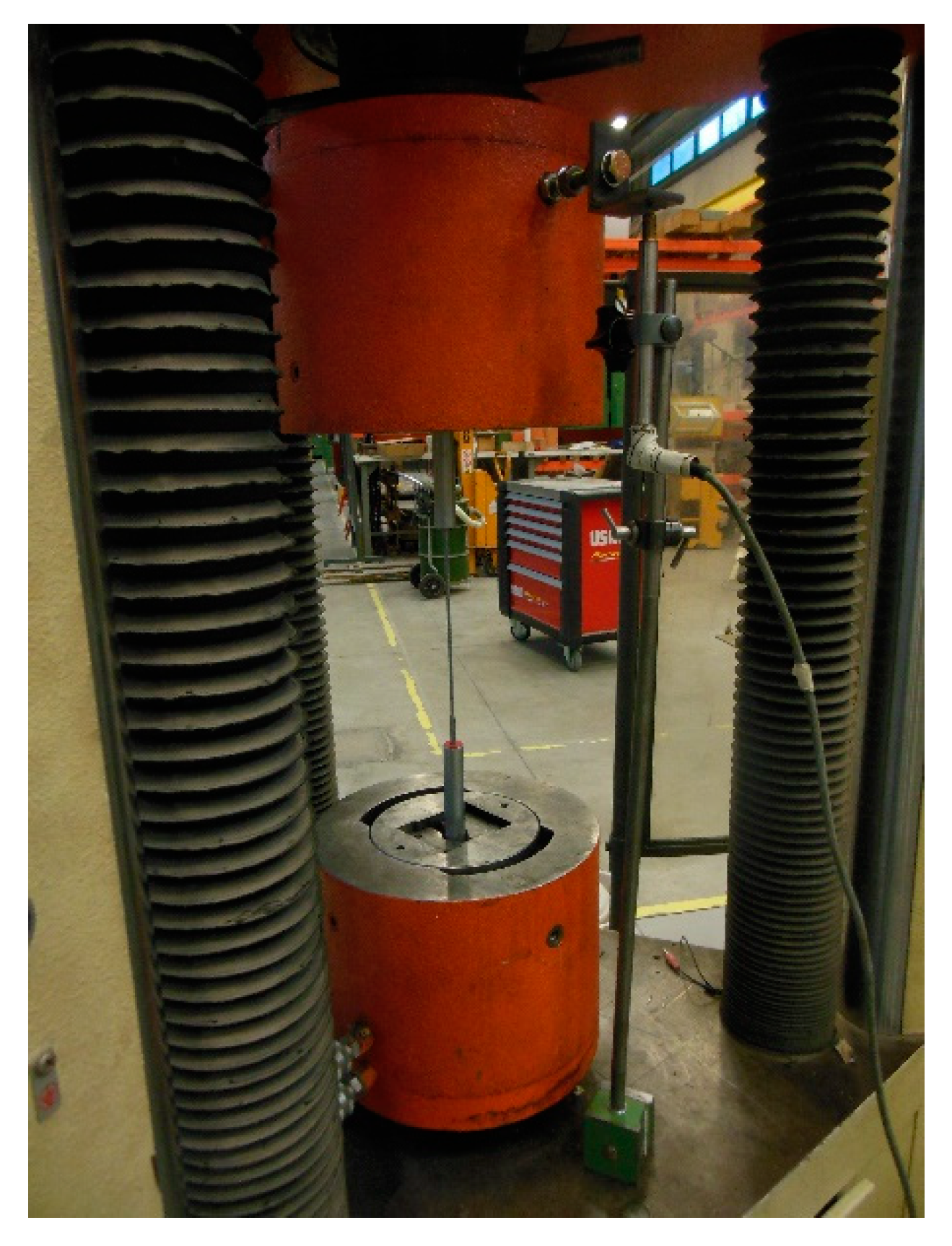
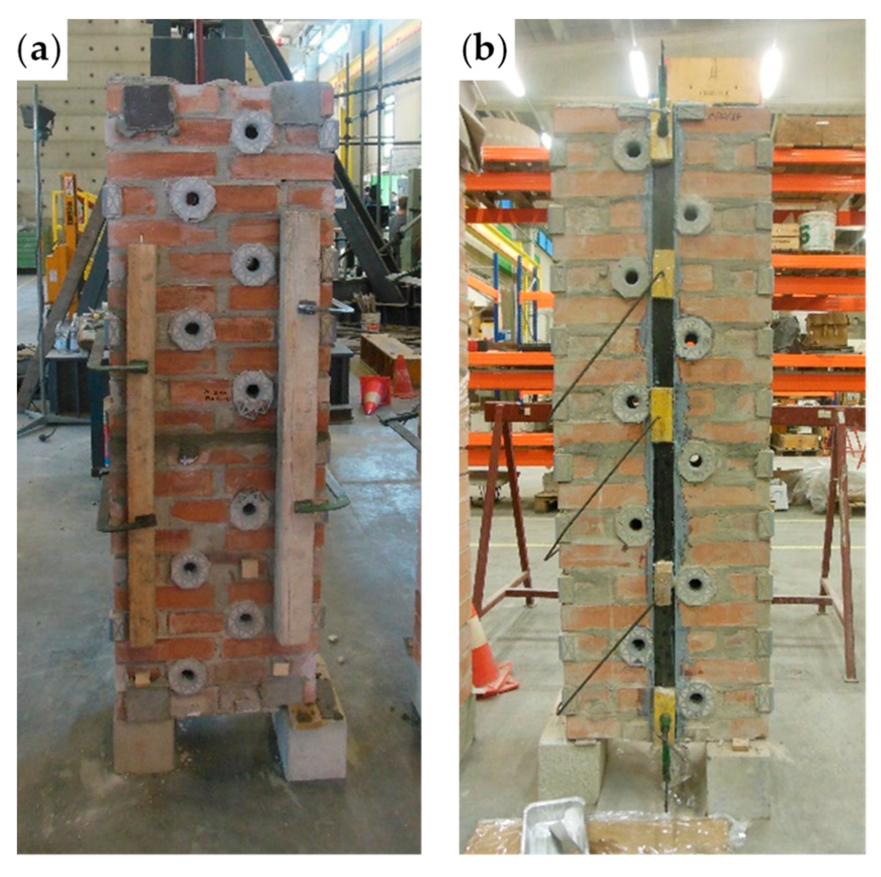
3. Experimental Program
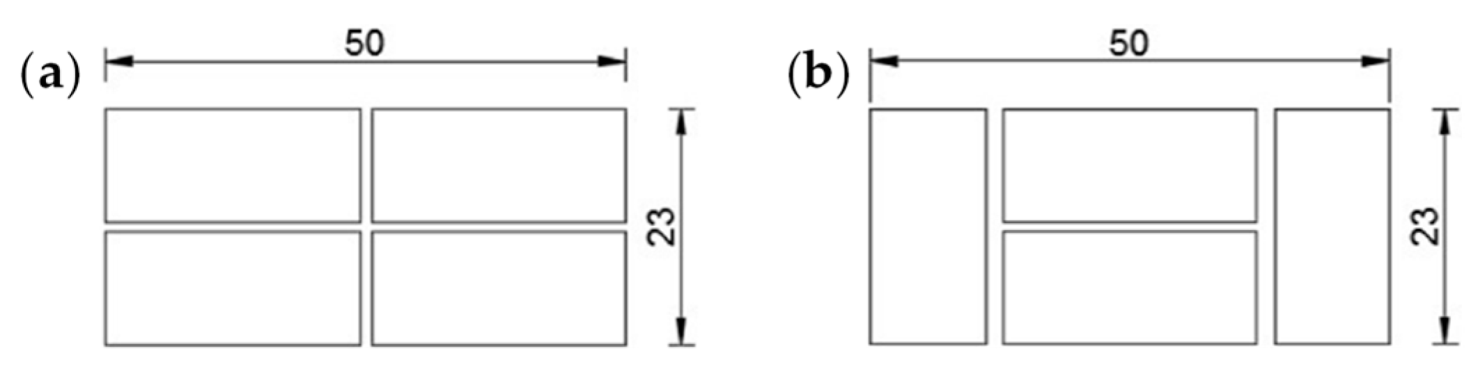
3.1. Bricks and Mortar
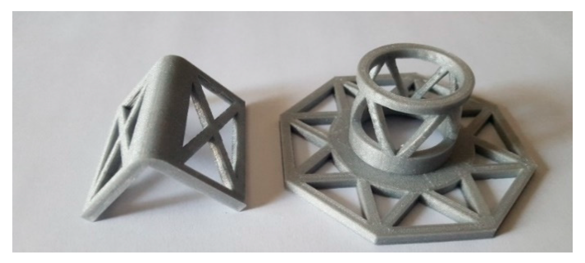
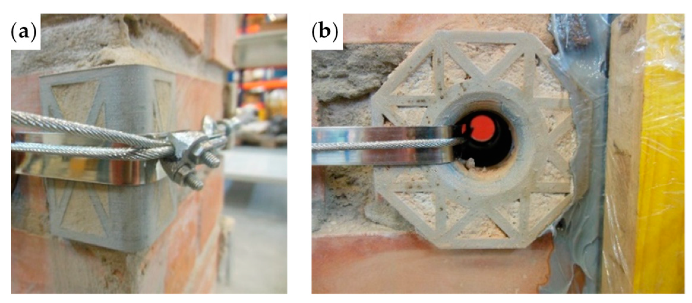
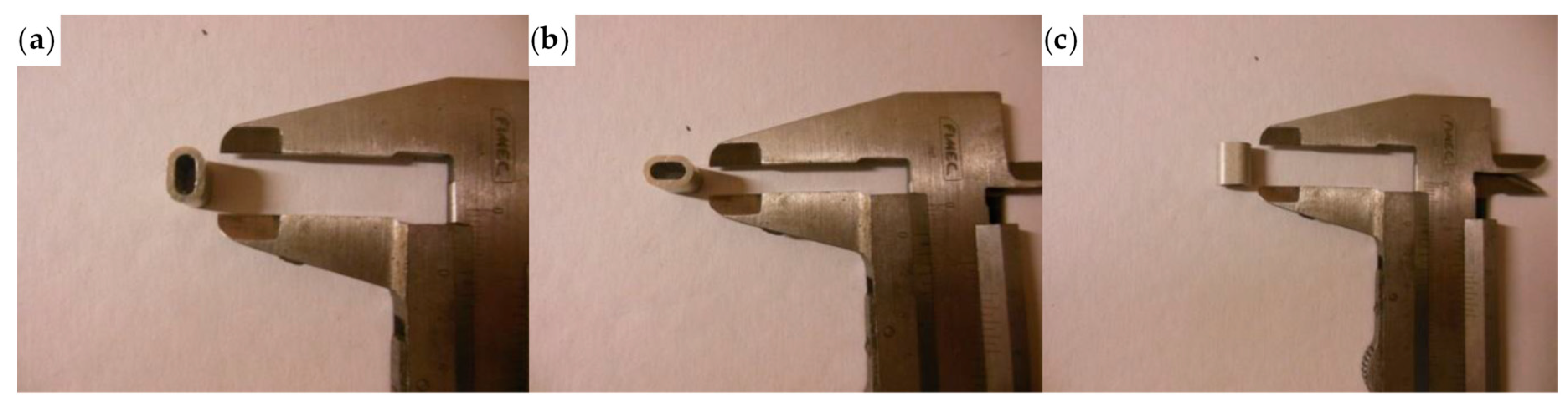
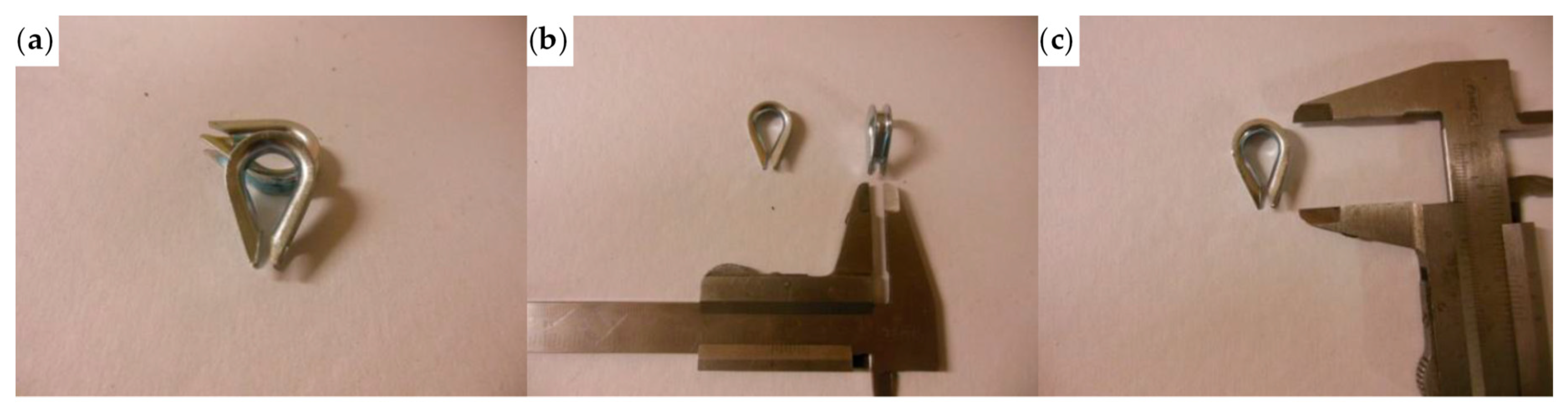
3.2. Protective Funnel-Shaped Plates and Rounded Angles
3.3. Mechanical Characterization of the Steel Wire Ropes
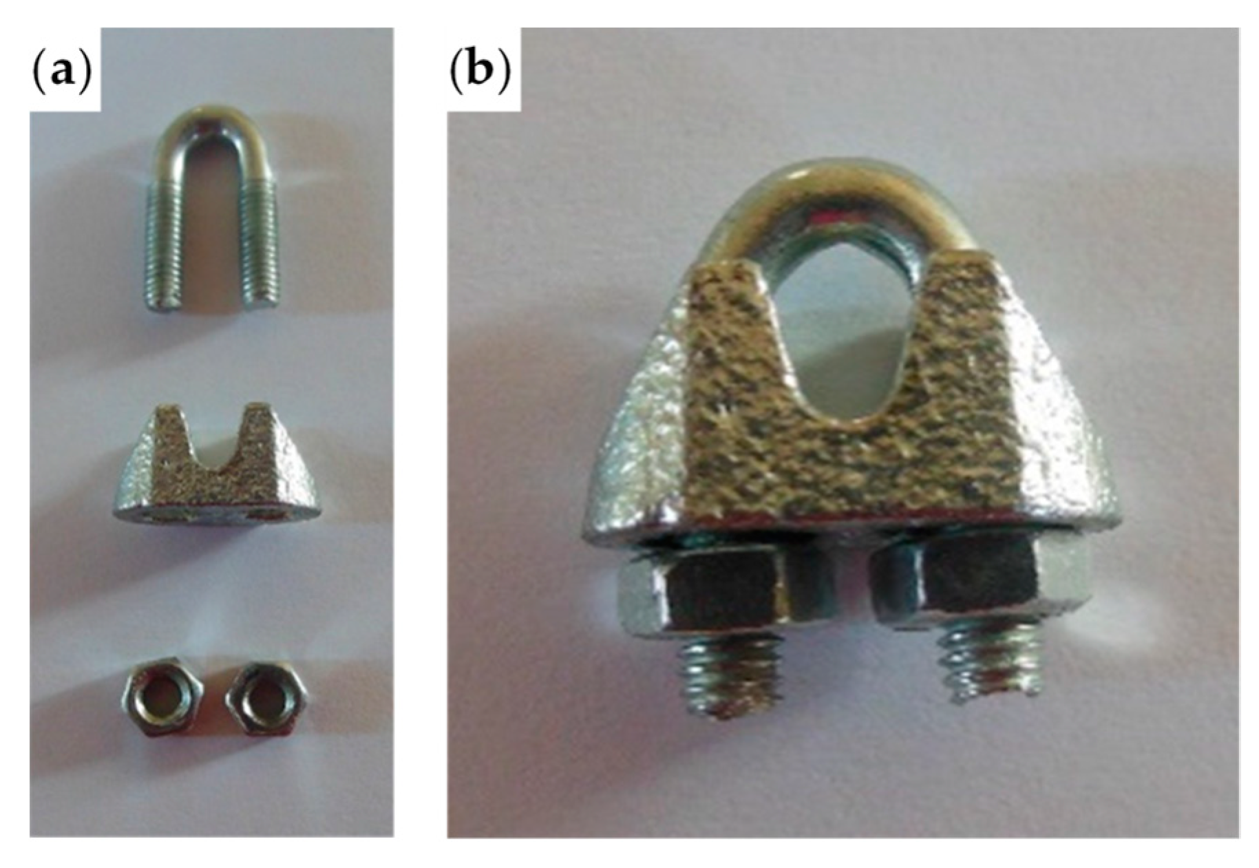
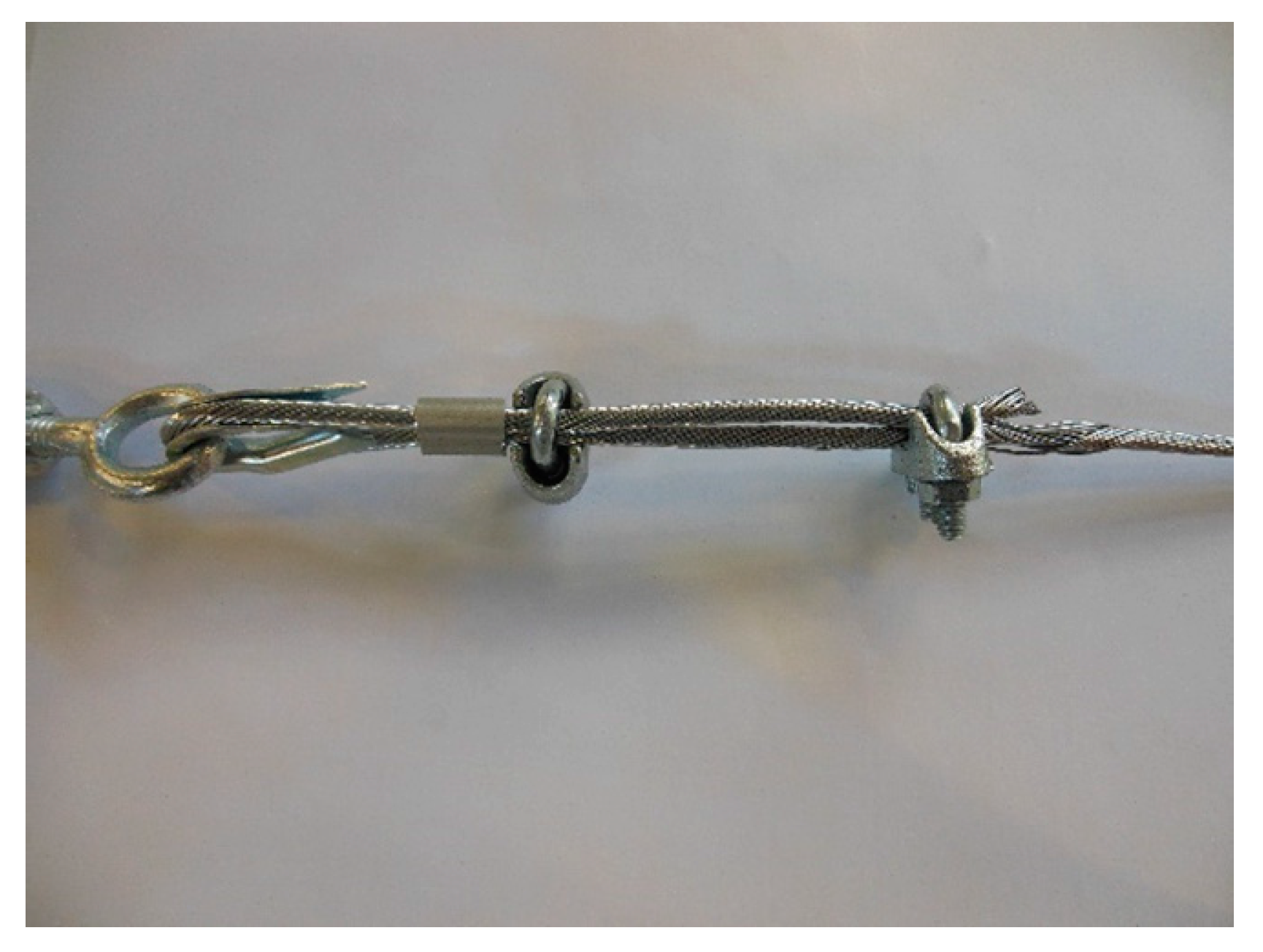
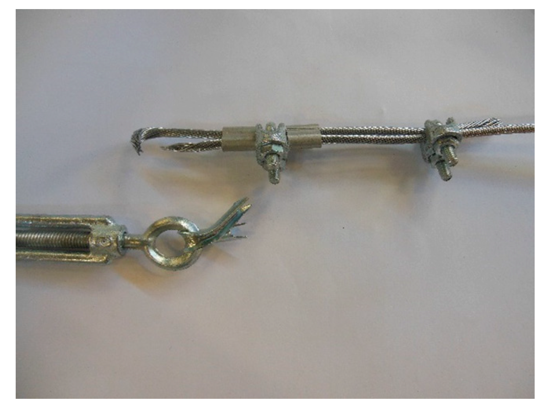
3.4. Mechanical Characterization of the Jionts
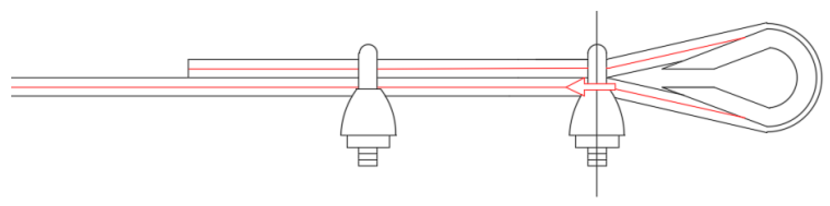
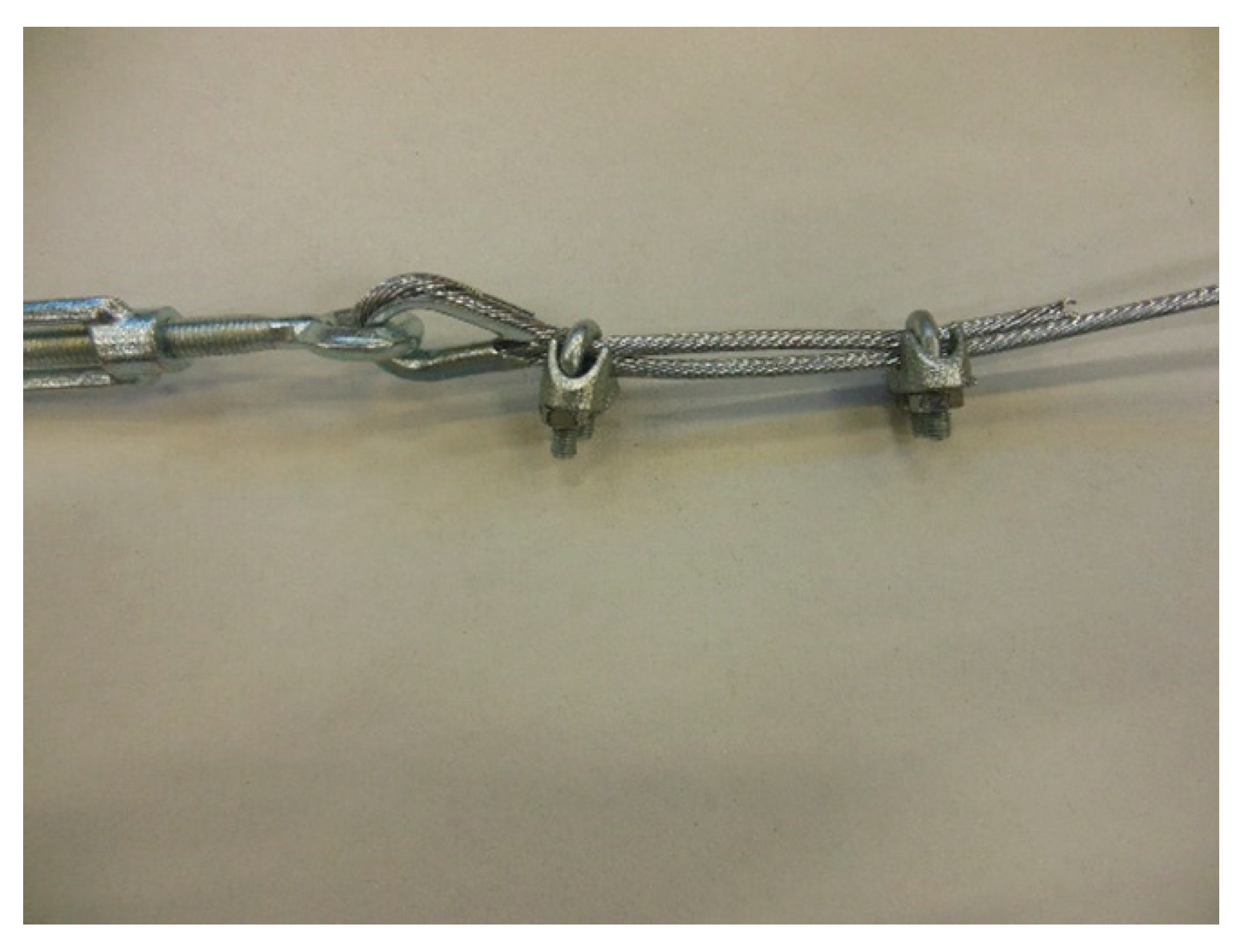
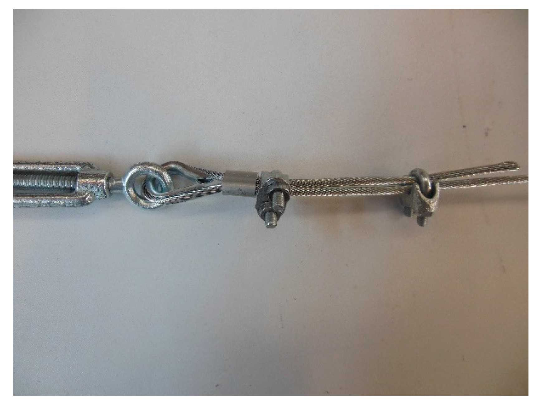
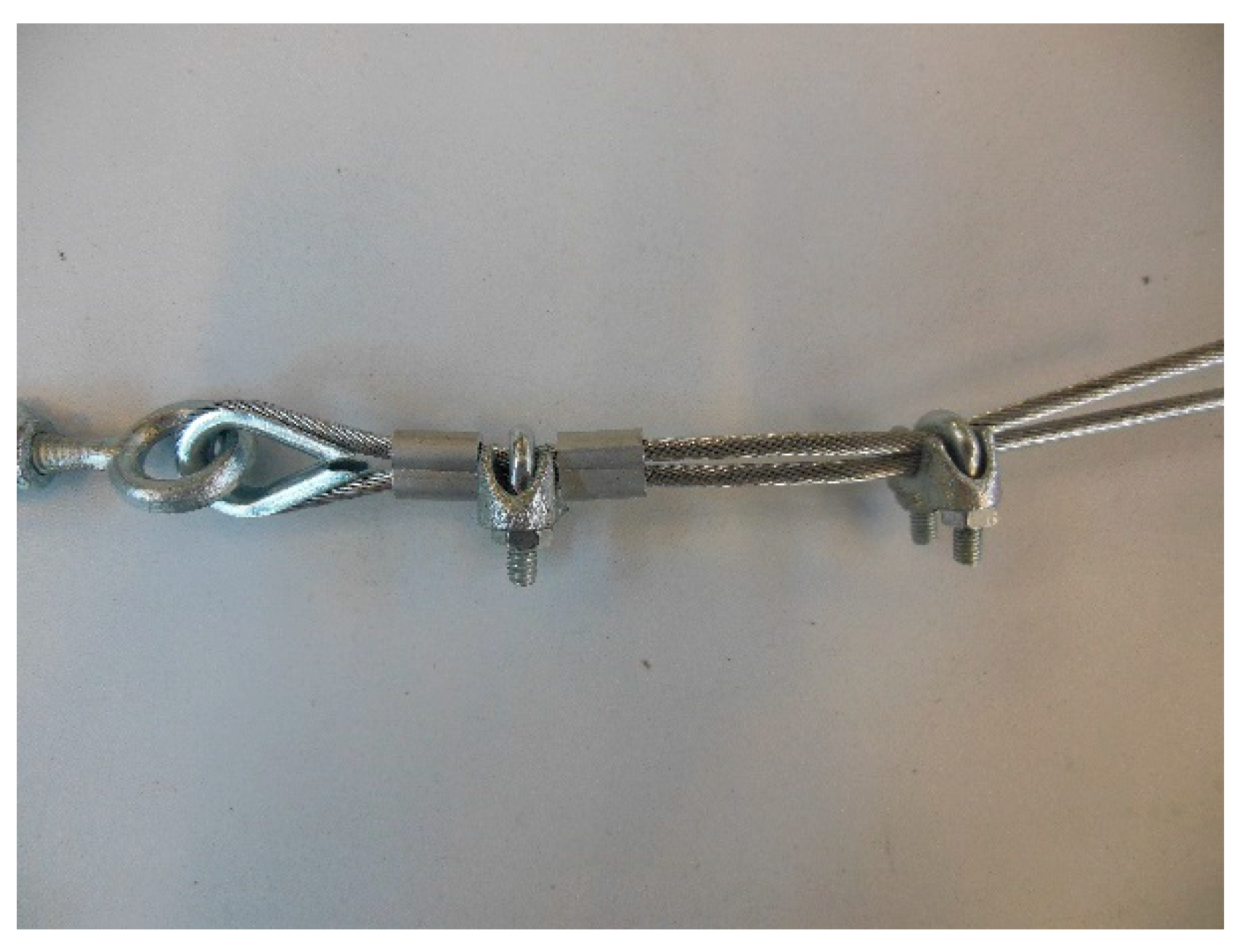
- 1 ferrule (Specimen 1, Figure 26);
- 2 ferrules in succession (Specimen 2, Figure 27);
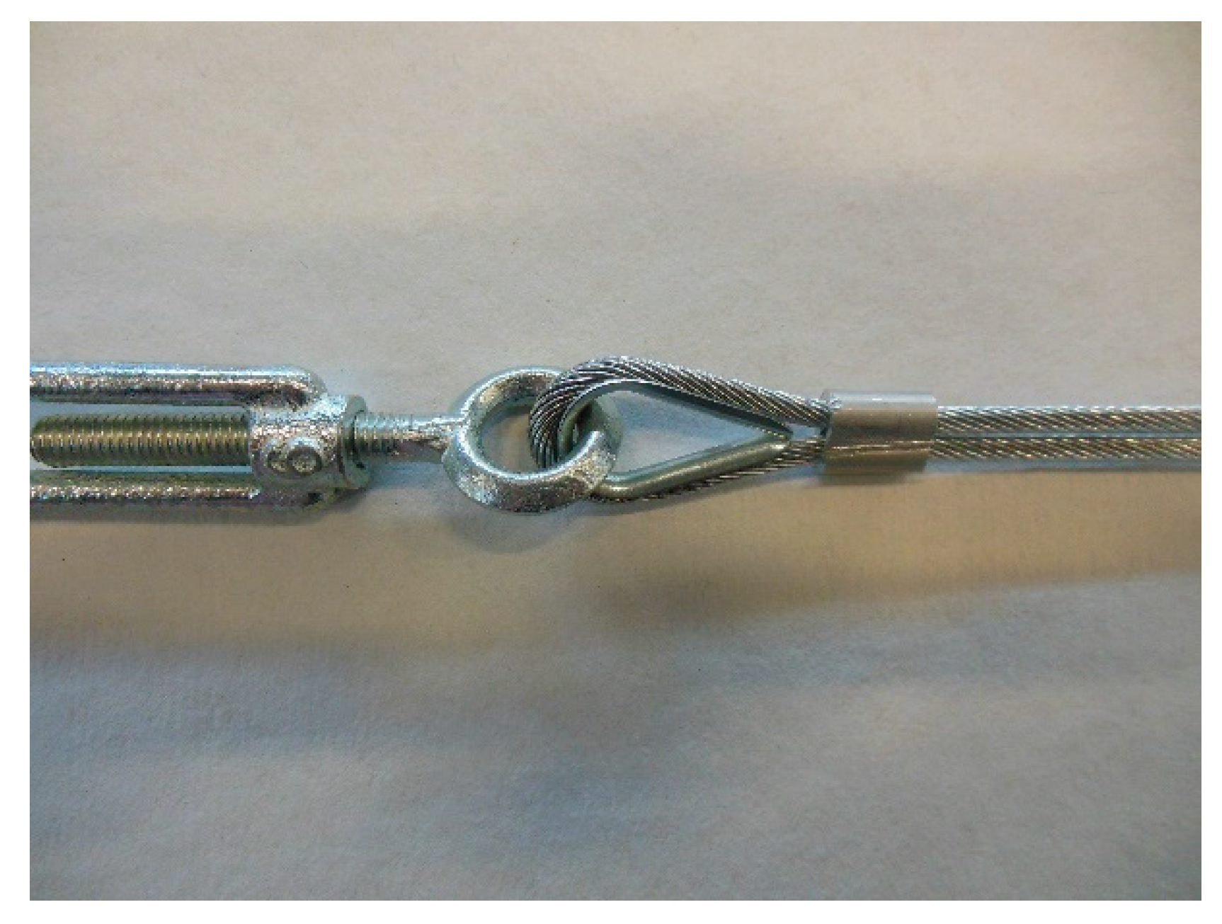
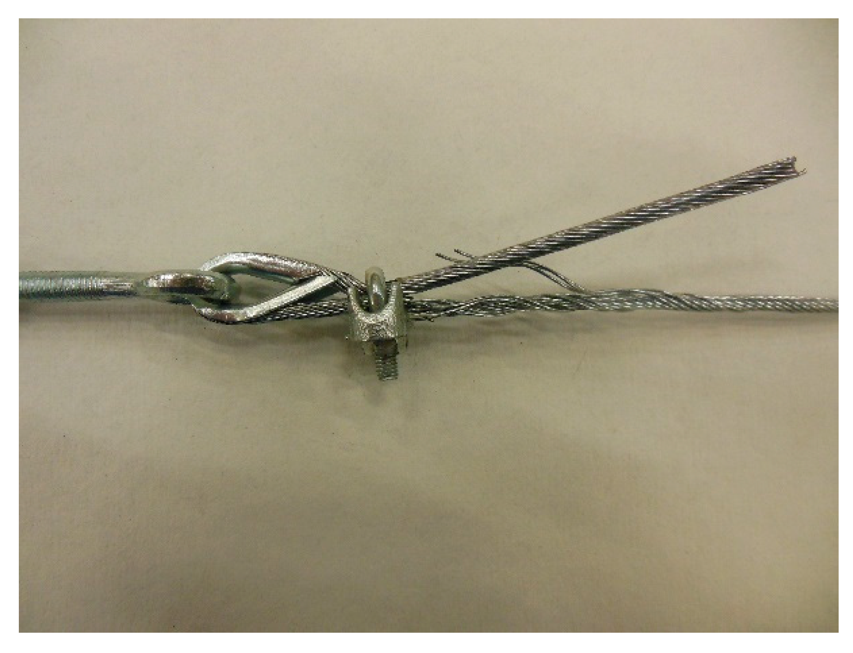
- 1 clip (Specimen 3, Figure 28);
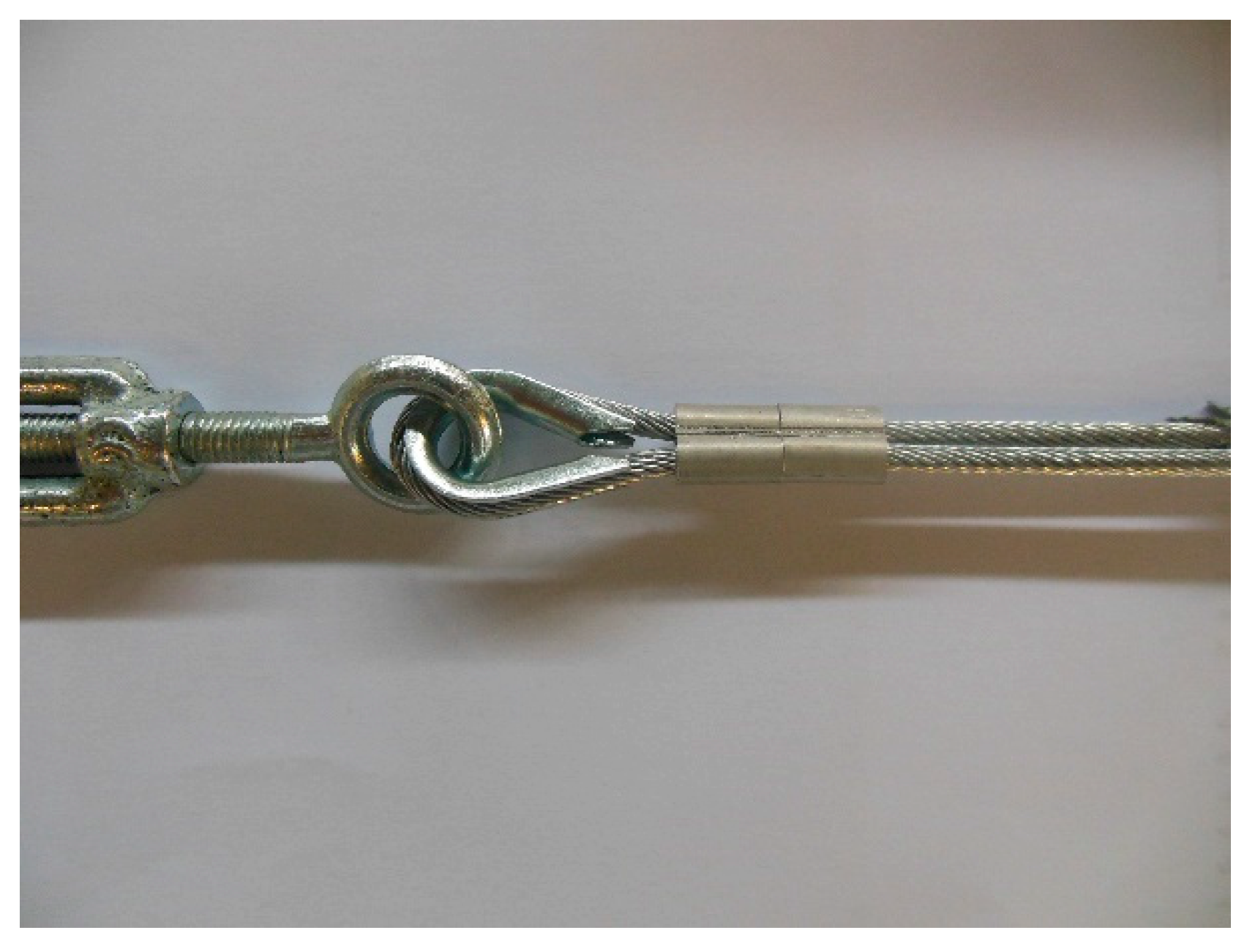
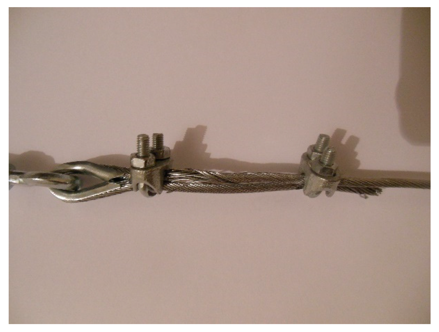
- 2 clips in succession (Specimen 4, Figure 29);
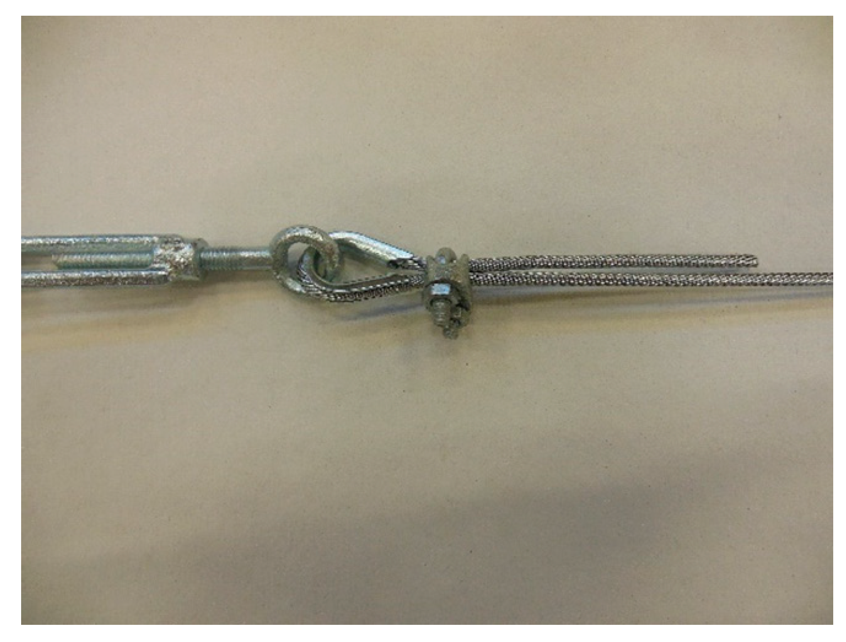
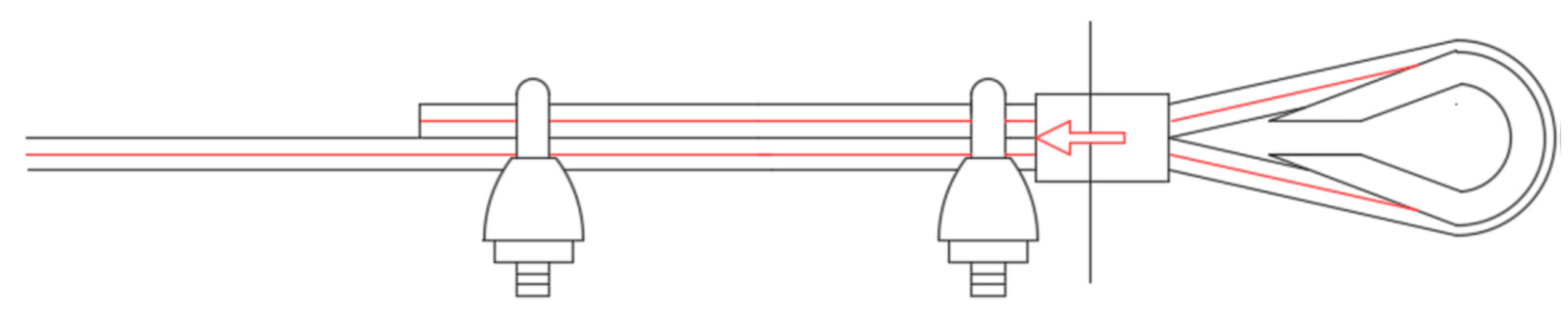
- 1 ferrule and 2 clips, in succession, starting from the Flemish eye (Specimen 5, Figure 30);
- 1 ferrule, 1 clip, a second ferrule, and a second clip, in succession, starting from the Flemish eye (Specimen 6, Figure 31);
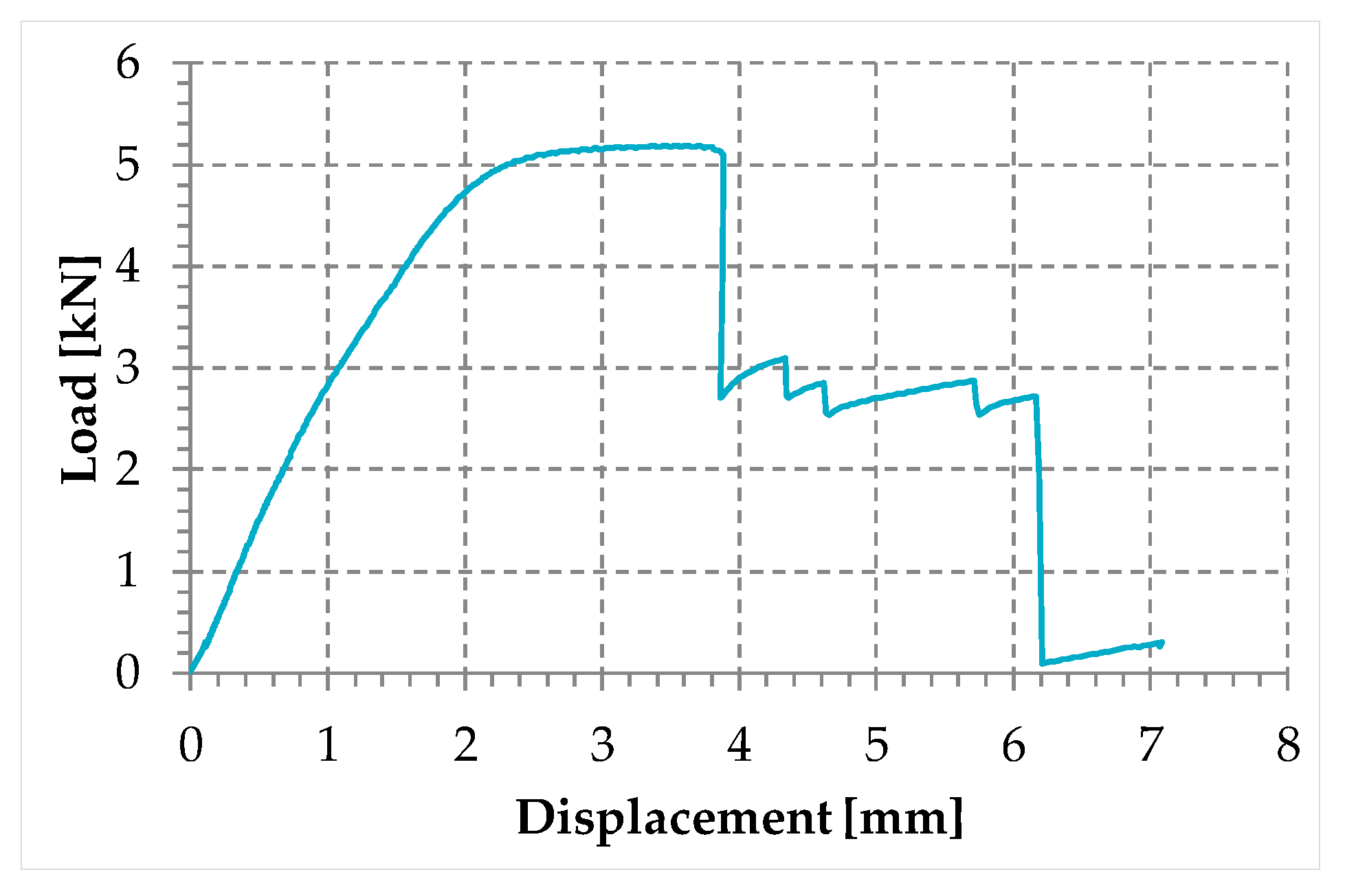
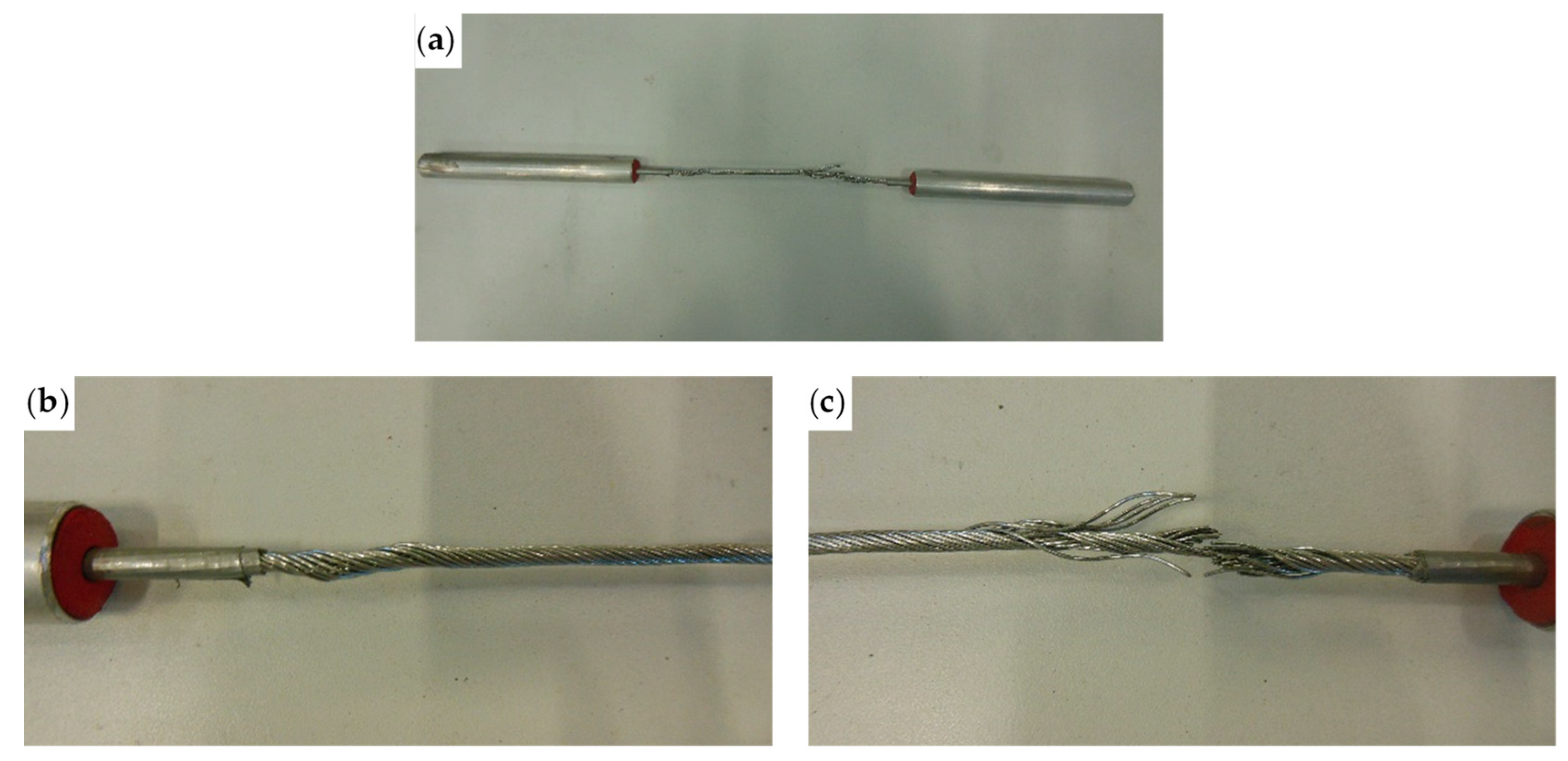
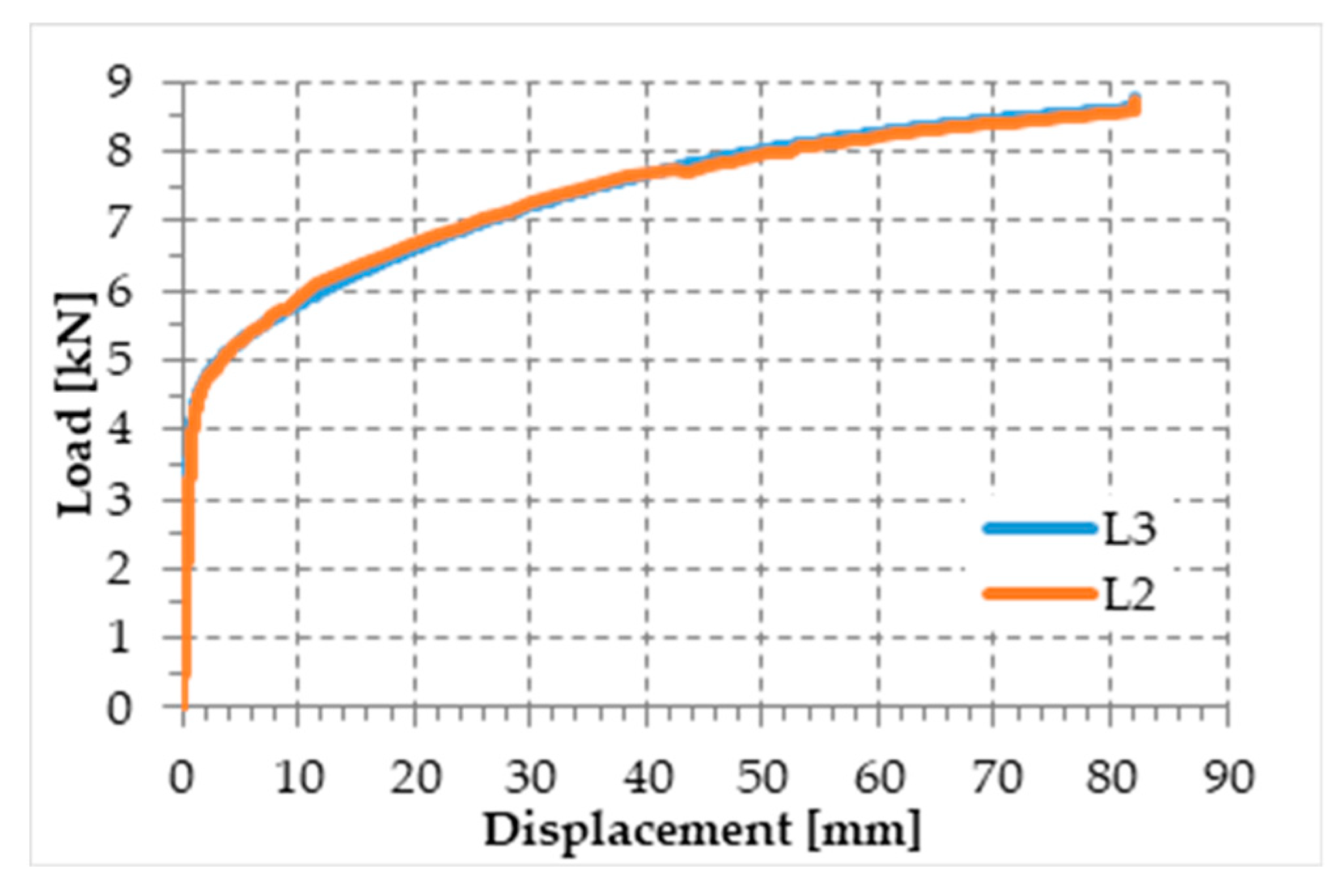
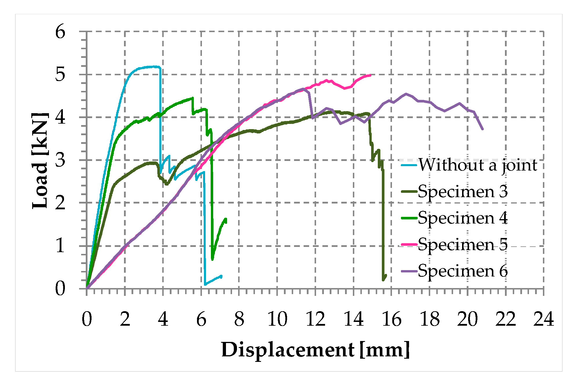
- The load of Specimen 3 increased linearly up to a value of about 2.4 kN. Then, the slope of the load/displacement diagram decreased due to the yield behavior of the steel wires and the load continued to increase monotonically up to a value of about 2.9 kN. At this point, the specimen suffered a load drop due to the squashing of the Flemish eyes. Once the squashing of the Flemish eyes was over, the load started to rise again, up to its maximum value. Afterwards, the fraying of the steel wires quickly led the specimen to failure. It is worth noting that the fraying started from one of the two clips used to close the Flemish eyes (Figure 34). In fact, the eccentricity of the load supplied to the steel wire rope—due to the non-perfect coaxiality between the turnbuckle and the “live” side—caused the flat bearing seat of the clip to rotate, until its edge came into direct contact with the steel wires. This caused the pinching and abrading of the steel wires and, consequently, their failures in rapid succession.
- The linear behavior of the load/displacement diagram of Specimen 4 terminated for a load value of about 3.4 kN, which corresponds to approximately 142% of the load at the end of the linear branch of Specimen 1. The yield behavior of the steel wires and squashing of the thimbles took place simultaneously from this moment forward, decreasing the slope of the load/displacement diagram but without causing any load drop. The slope of the linear branch is greater than the slope of the linear branch for Specimen 3, which means that Specimen 4 is stiffer than Specimen 3. Actually, the stiffness of Specimen 4 is comparable to the stiffness of the steel wire rope without a joint. The yield behavior and squashing processes terminated with the fraying of the steel wires, which is responsible for the “step behavior” of the last part of the load/displacement diagram: Each load drop in this final part is the consequence of the failure of one or more steel wires. The fraying started from a clip, the first from the Flemish eye (Figure 35). As for Specimen 3, the cause for this lies in the non-perfect coaxiality between the turnbuckle and the “live” end (Figure 25). However, the second clip—that forces the part of the “dead” side between the two clips to bear load—partially eliminates the torsion of the first clip, delaying the fraying. This could also be the reason for the greater stiffness and maximum load of Specimen 4.
- The purpose of the fifth fastening scheme was to eliminate the torsion of the first clip of the fourth fastening scheme, that is, the clip closest to the Flemish eye. In other words, the function of the ferrule was to center the load on the two clips (Figure 36). Specimen 5 did not actually fray near the first clip (Figure 37): It frayed near the second clip. The improved load centering allowed the specimen to withstand a higher ultimate load, comparable to the ultimate load of the steel wire rope without a joint. However, the ferrule caused an excessive deformation of the Flemish eyes, as for Specimens 1 and 2. This greatly reduced the stiffness of the specimen.
- The sixth fastening scheme introduces an additional ferrule between the two clips to eliminate even the rotation of the second clip, with the aim of preventing the specimen from fraying near both clips. The second ferrule actually further improved the load centering, eliminating fraying near both clips. However, this concentrated the deformation phenomena on the thimble that twisted, cutting off the steel wires (Figure 38). The twisting of the thimble occurred due to the excessive squashing of the Flemish eye. In fact, once the two ends of the thimble come into contact, the further squashing of the Flemish eye is possible only by forcing the two ends of the thimble to slide one over the other in the direction orthogonal to the load. This causes the twisting borders of the thimble to cut the steel wires. Even in Specimen 5 the excessive deformation of the Flemish eye caused a twist of the thimble (Figure 35), but this did not lead to damage to the steel wires. Lastly, the concentration of the deformations on the Flemish eyes greatly reduced the stiffness of Specimen 6, as for Specimen 5.
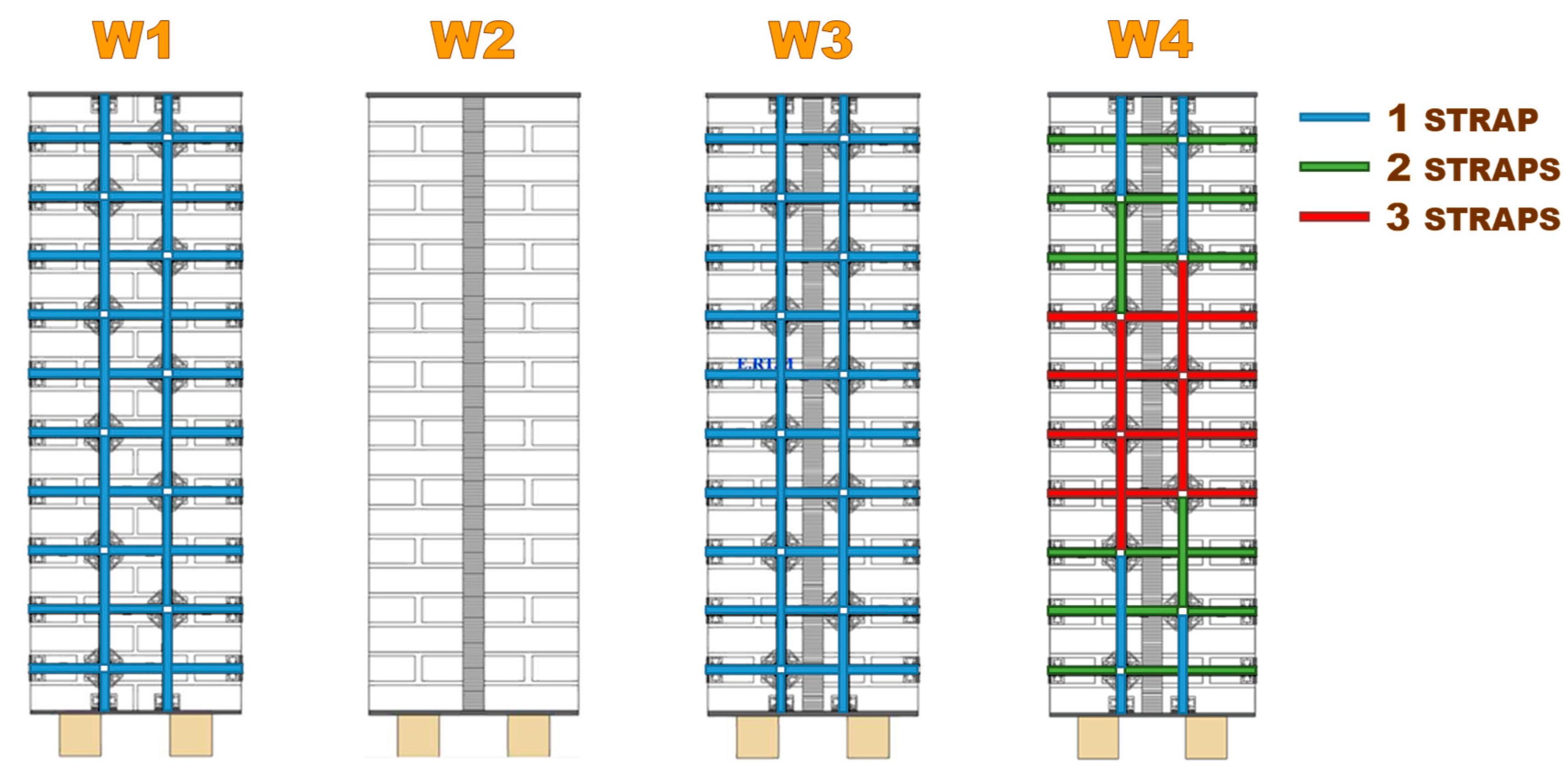
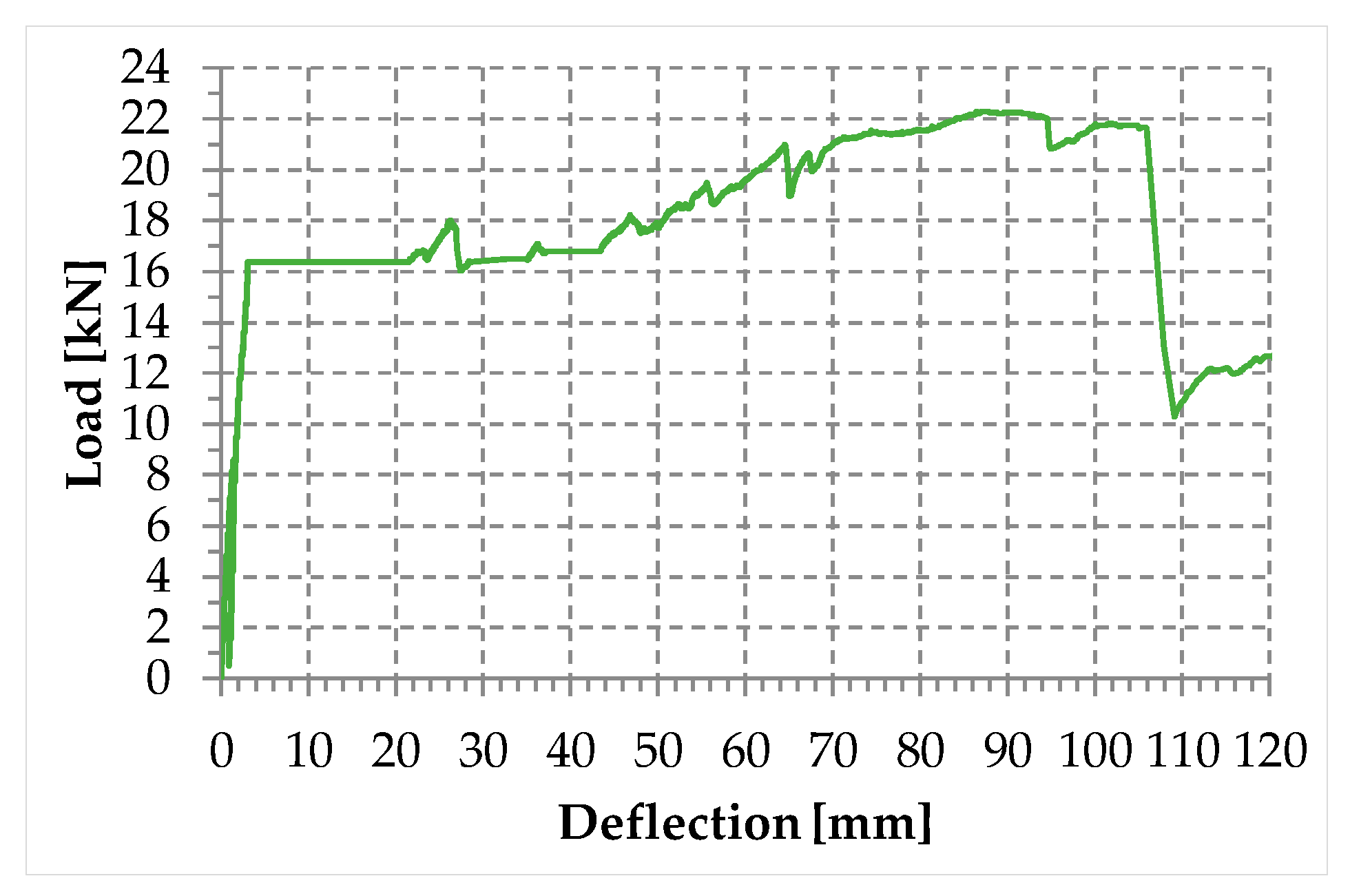
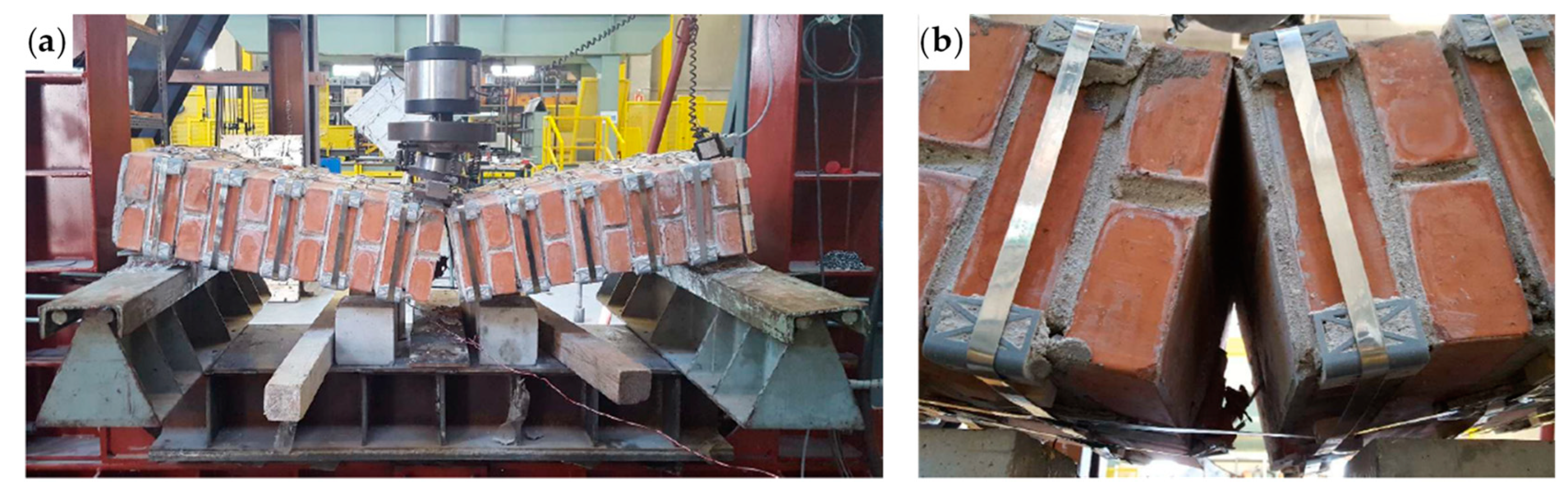
3.5. Three-Point Bending Flexural Test on a Masonry Specimen
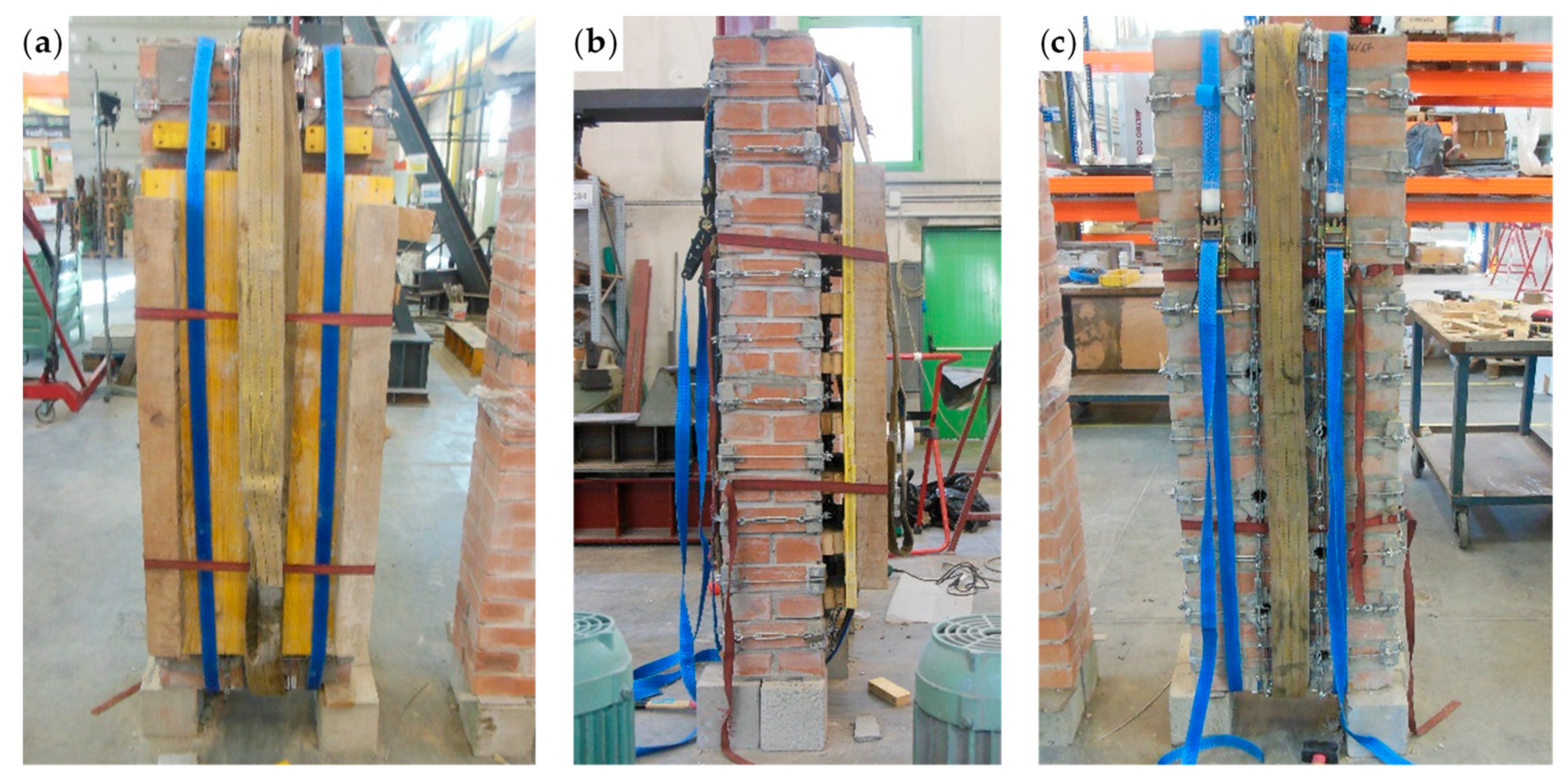
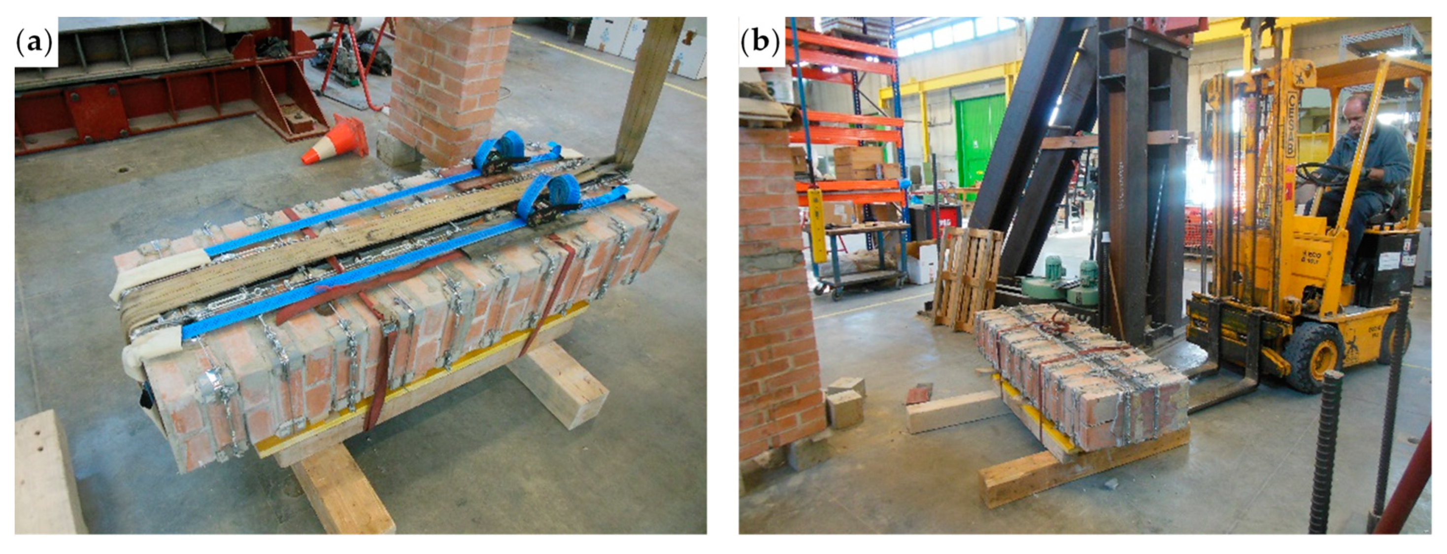
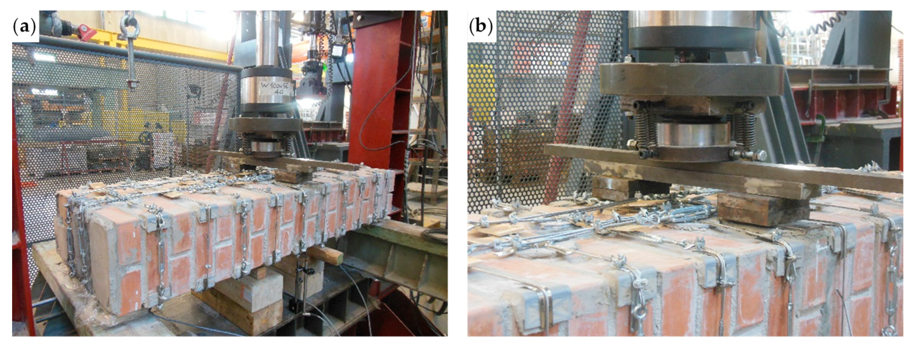
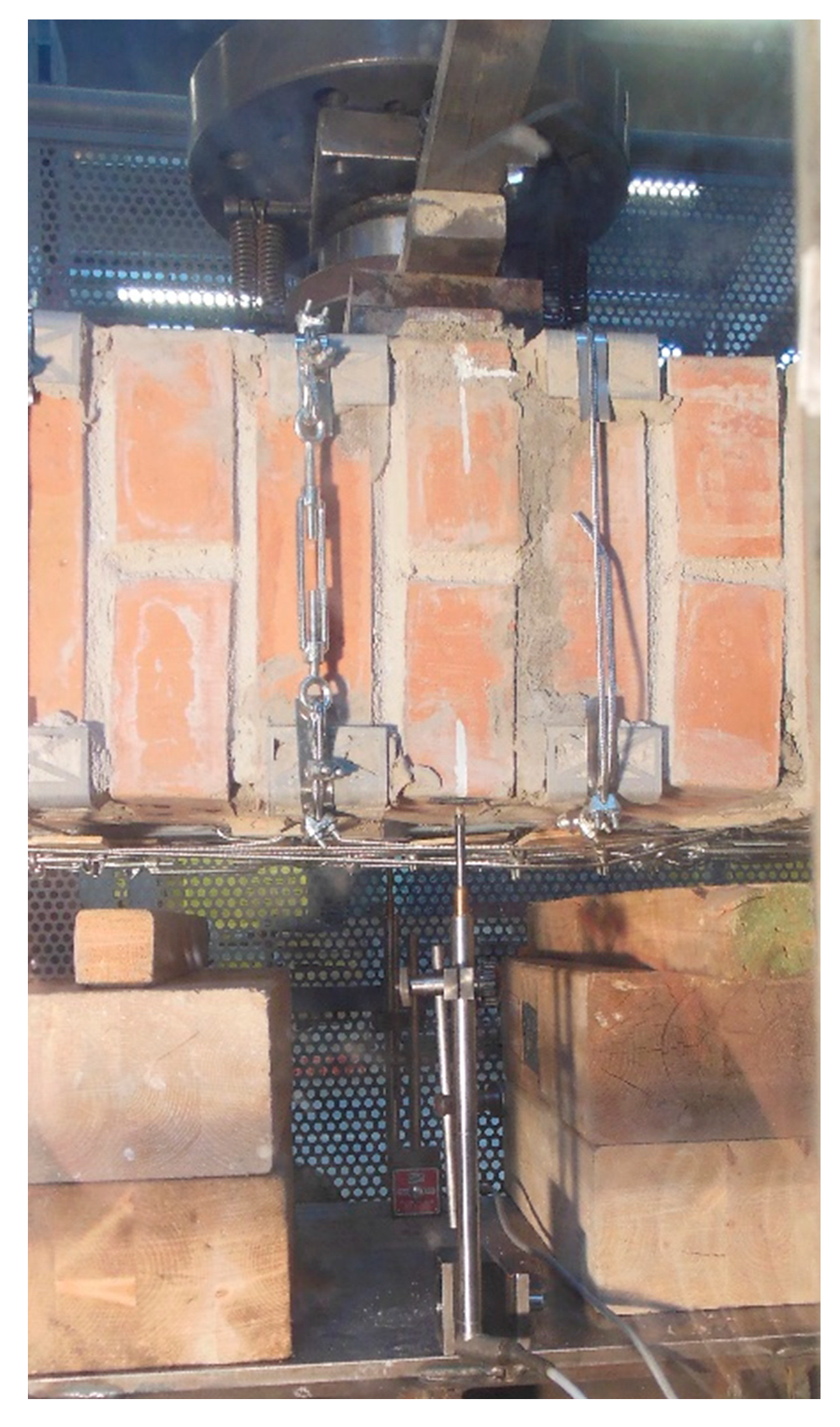
3.5.1. Preparation of the Specimen and Test Setup
- Removal of the specimen from the testing machine;
- Removal of all the straps from the specimen;
- Overturning in the vertical configuration of the two parts resulting from the failure;
- Restoration of the cavity for the passage of the straps near the disconnected cross-section, inserting a steel tube of the same external diameter as the drilled holes;
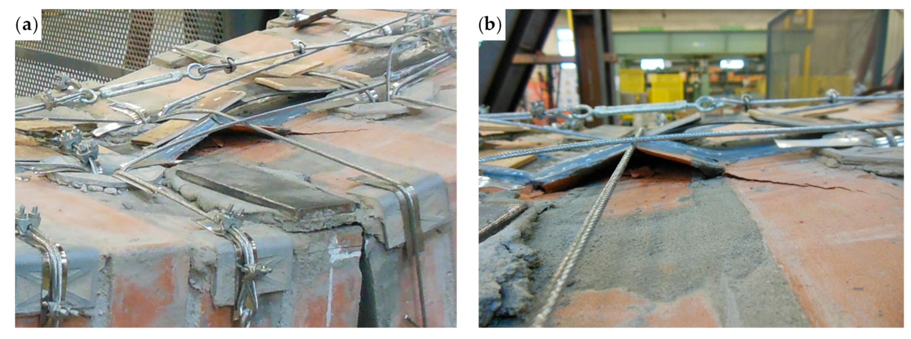
- Restoration of the disconnected mortar bed joint (Figure 41a), after lifting and holding of the upper part of the specimen in position with a girder crane;
- Maturing of the mortar on the restored mortar bed joint;
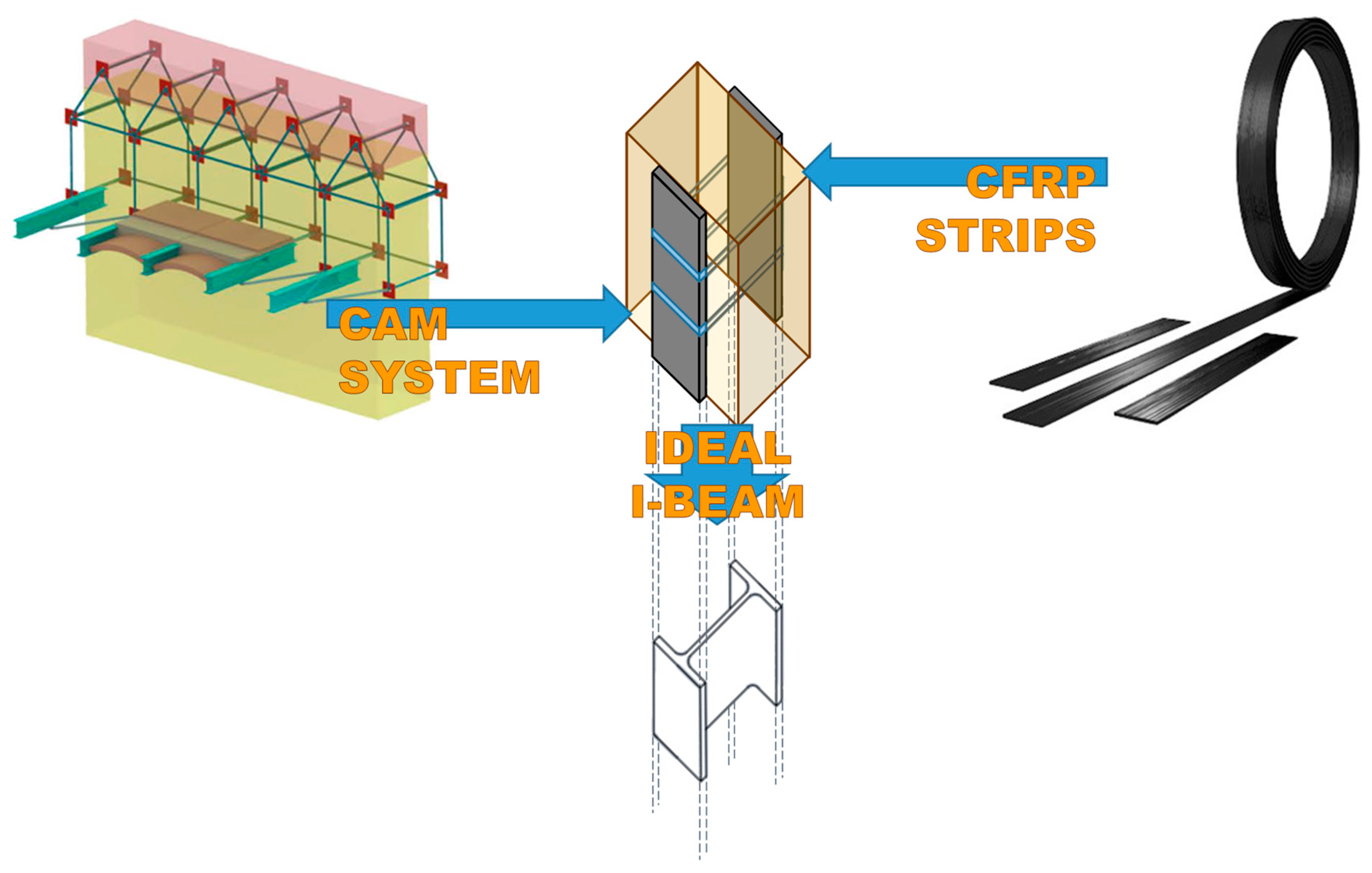
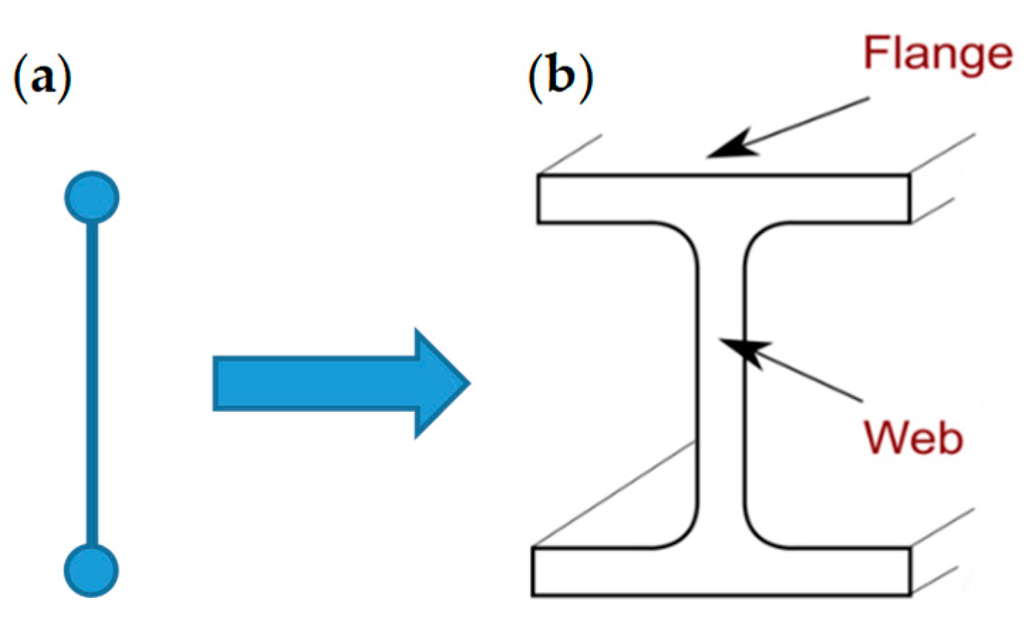
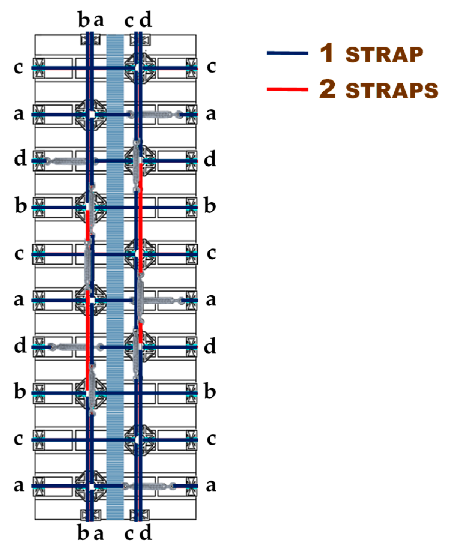
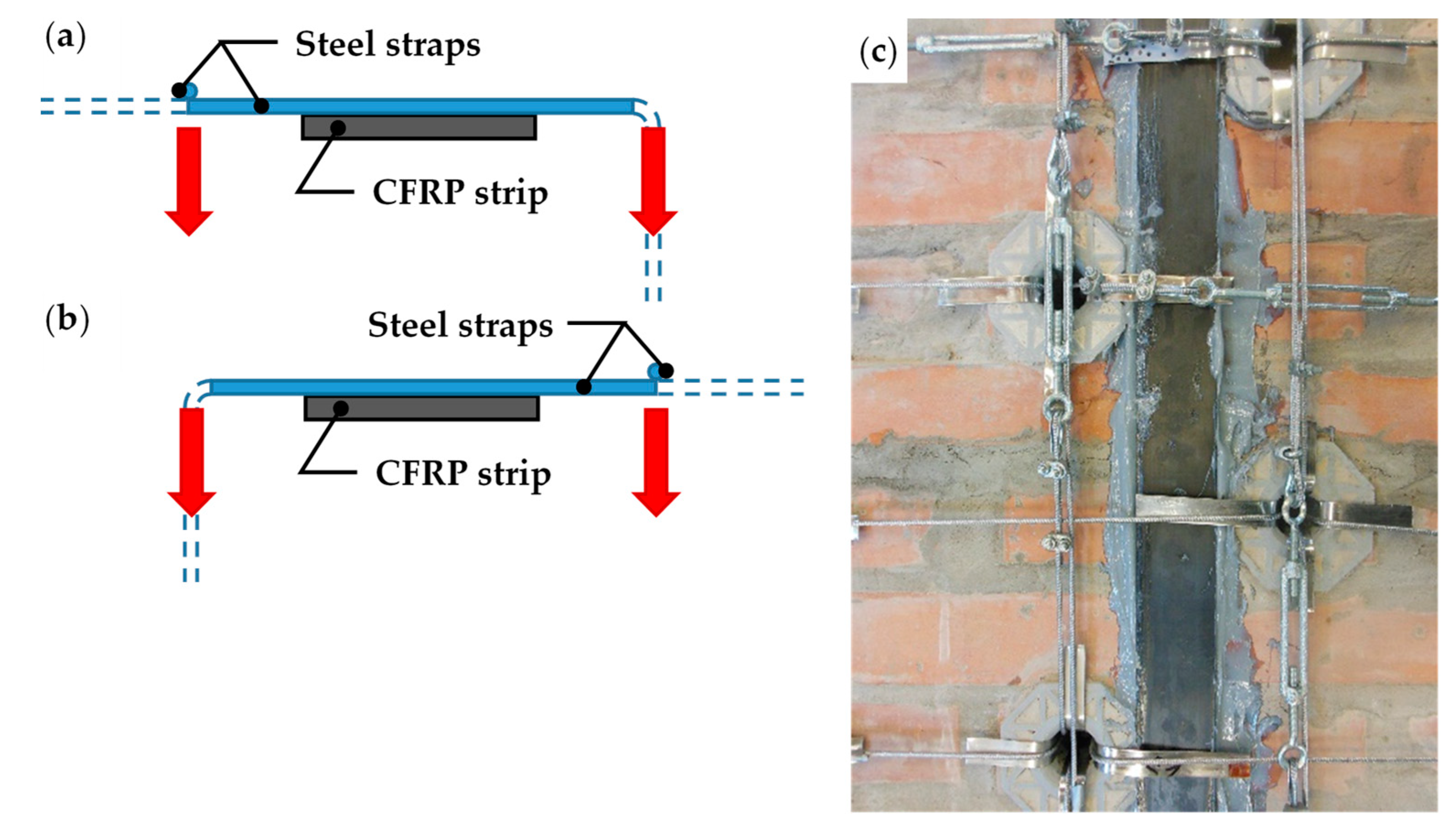
- Application of longitudinal CFRP strips (50 mm × 1.2 mm), on both main faces of the restored specimen (Figure 41b);
- Application of the straps on the restored specimen (Figure 42).
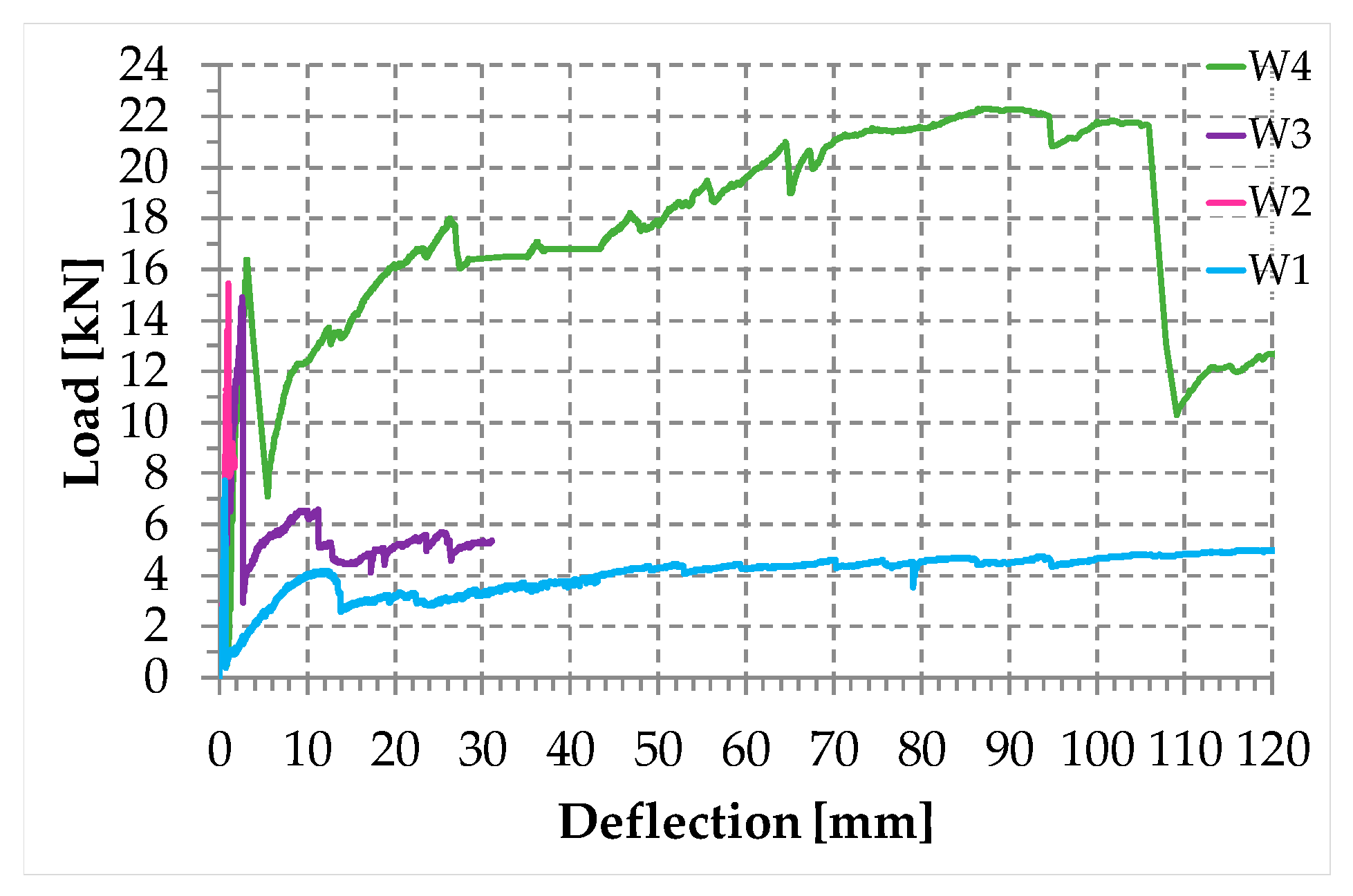
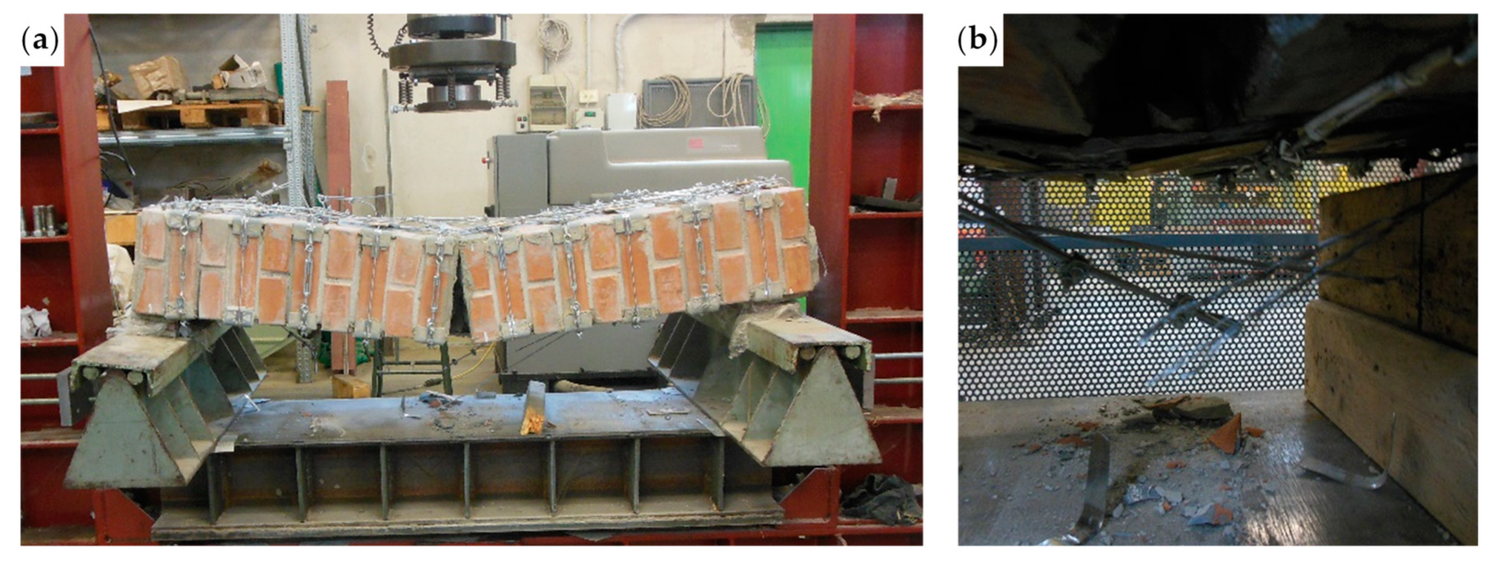
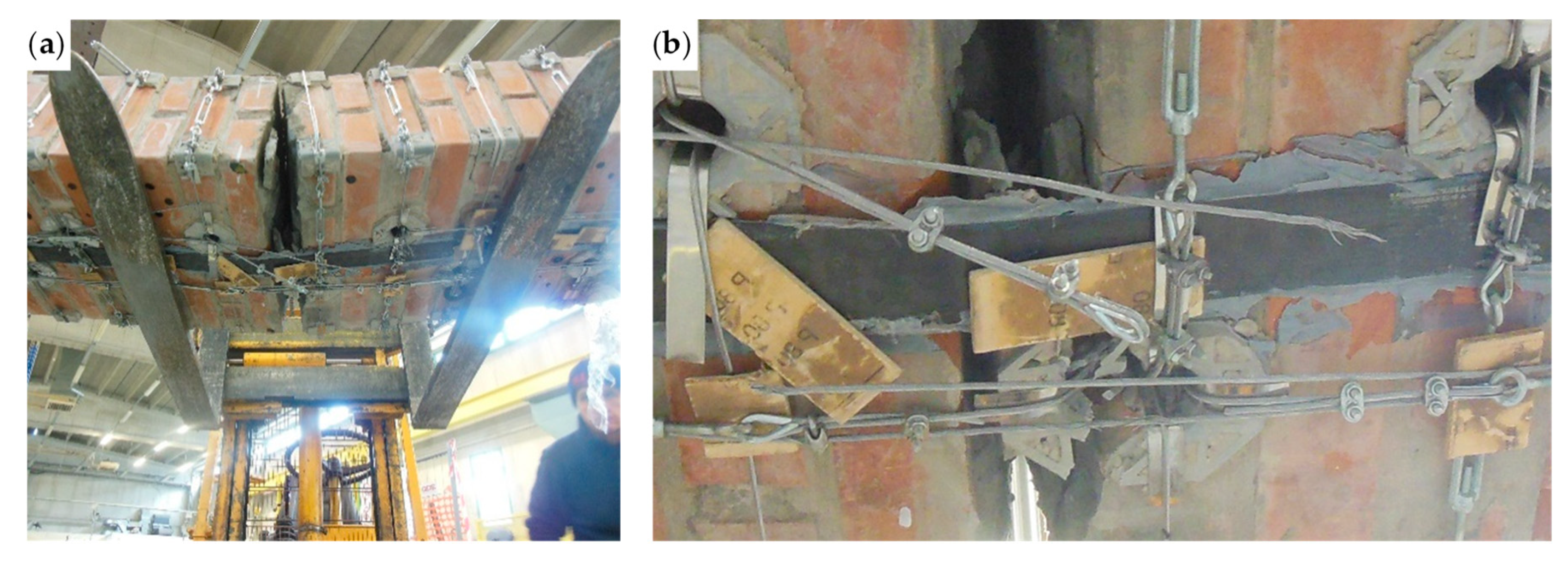
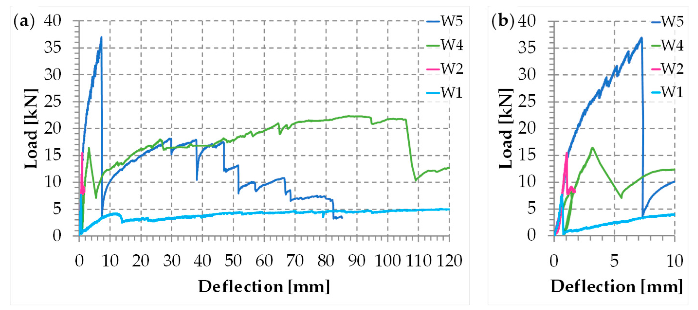
3.5.2. Results and Discussion
4. Conclusions
5. Future Developments
- In order to avoid that the breakage of one or more funnel-shaped elements interrupts the chain of the longitudinal straps, it may be useful to re-design the 3D-printed elements or use a more resistant material for the protective elements.
- In order to avoid that the geometric effects due to the relative rotations around the inner hinge frustrate the action of the longitudinal straps on the transverse straps, it may be useful to decrease the length of the loops near the middle cross-section, where the inner hinge has the maximum probability of localization.
- In order to avoid that excessive post-delamination fraying leads to the collapse of the structural element, it may be useful to use longitudinal stainless steel ribbons in addition to the longitudinal steel wire ropes, at least near the middle cross-section. Since the function of the additional steel ribbons is only to safeguard life, they do not need a pre-tension.
- In order to avoid excessive load drops and dangerous release of energy at the time of delamination—which are peculiarities of epoxy resins—it may be useful to replace the epoxy resin (organic) with a mortar matrix (inorganic).
- First ascending branch: The specimen remains un-cracked.
- Horizontal branch (constant stress at increasing strains): Multiple cracks develop in the mortar, after the first cracking. During this phase, the area of the resistant cross-section of the mortar decreases progressively [75,76,77,78,79,80] due to the gradual development of the crack pattern that causes a progressive transfer of stress from the mortar to the fibers of the open-mesh textile.
- Second ascending branch, characterized by a reduced slope with respect to that of the first branch: The crack pattern has reached its maximum development and the residual stiffness is due to the fibers of the textile, up to the break.
Funding
Acknowledgments
Conflicts of Interest
References
- Ferretti, E.; Pascale, G. Combined Strengthening Techniques to Improve the Out-of-Plane Performance of Masonry Walls. Materials 2019, 12, 1171. [Google Scholar] [CrossRef] [PubMed]
- Ferretti, E.; Pascale, G. Some of the Latest Active Strengthening Techniques for Masonry Buildings: A Critical Analysis. Materials 2019, 12, 1151. [Google Scholar] [CrossRef] [PubMed]
- Ferretti, E. Effectiveness of Active Confinement Techniques with Steel Ribbons: Masonry Buildings. Eur. J. Eng. Form. Sci. 2018, 2, 18–30. [Google Scholar] [CrossRef]
- Ferretti, E. Attaining a Beam-Like Behavior with FRP Strips and CAM Ribbons. Eur. J. Eng. Formal Sci. 2018, 2, 7–17. [Google Scholar] [CrossRef]
- Cilia, M.; Cipolla, I.; Colajanni, P.; Marnetto, R.; Recupero, A.; Spinella, N. Prove sperimentali su travi in c.a. rinforzate con metodo CAM®: Valutazione del comportamento a taglio. Progett. Sismica 2015, 7, 93–108. [Google Scholar]
- Dolce, M.; Nigro, D.; Ponzo, F.C.; Marnetto, R. The CAM System for the Retrofit of Masonry Structures. In Proceedings of the 7th International Seminar on Seismic Isolation, Passive Energy Dissipation and Active Control of Vibrations of Structures, Assisi, Italy, 2–5 October 2001. [Google Scholar]
- Dolce, M.; Ponzo, F.C.; Di Croce, M.; Moroni, C.; Giordano, F.; Nigro, D.; Marnetto, R. Experimental Assessment of the CAM and DIS-CAM Systems for the Seismic Upgrading of Monumental Masonry Buildings. In Proceedings of the PROHITECH 09, 1st International Conference on Protection of Historical Constructions, Rome, Italy, 21–24 June 2009; CRC Press/Balkema: Leiden, The Netherlands, 2009; pp. 1021–1028. [Google Scholar]
- Dolce, M.; Ponzo, F.C.; Goretti, A.; Moroni, C.; Giordano, F.; De Canio, G.; Marnetto, R. 3D Dynamic Tests on 2/3 Scale Masonry Buildings Retrofitted with Different Systems. In Proceedings of the 14th World Conference on Earthquake Engineering, Beijing, China, 12–17 October 2008. [Google Scholar]
- Leonori, M.; Vari, A. L’Influenza della Tipologia di Terreno sui Meccanismi Locali di Collasso degli Edifici in Muratura e Miglioramento Sismico con il Sistema CAM® [The Influence of the Type of Land on Local Mechanisms of Collapse of Masonry Buildings and Seismic Improvement with the CAM® System]. In Proceedings of the Dynamic Interaction of Soil and Structure (DISS_15), 4th International Workshop on Archaeology, Cryptoportici, Hypogea, Geology, Geotechnics, Geophysics, Rome, Italy, 12–13 November 2015; Monti, G., Valente, G., Eds.; DISS_Edition c/o DICEAA—L’Aquila University: L’Aquila, Italy, 2015; pp. 1–15. [Google Scholar]
- Marnetto, R. Sviluppo ed applicazioni delle tecniche antisismiche presso la società TIS SpA di Roma. In Proceedings of the Seminario di Studi sui Sistemi e Tecnologie Antisismici, Rome, Italy, 12 September 2007; pp. 2–27. [Google Scholar]
- Marnetto, R.; Vari, A. Linee Guida—Cuciture Attive per la Muratura: Procedura Generale per la Progettazione, Modellazione, Calcolo e Verifica di Edifici in Muratura Rinforzati con il Sistema di Cucitura Attiva CAM [Active Tying for Masonry: General Procedure for the Design, Modeling, Calculation, and Verification of Masonry Buildings Reinforced with the CAM Active Tying System]; EDIL CAM Sistemi S.r.l.: Rome, Italy, 2015. [Google Scholar]
- Marnetto, R.; Vari, A.; Marnetto, L.; Leonori, M. Conservare l’Edilizia in Muratura: Il Sistema CAM—Cuciture Attive dei Manufatti [Conserving the Building Heritage in Masonry: The CAM System—Active Confinement of Manufactured Buildings]; Edizioni PREprogetti: Rome, Italy, 2014. [Google Scholar]
- Ministero delle Infrastrutture e dei Trasporti. Aggiornamento delle Norme Tecniche per le Costruzioni [Updating of the Technical Standards for Constructions]; Decreto; Gazzetta Ufficiale della Repubblica Italiana: Rome, Italy, 2018. [Google Scholar]
- Presidente del Consiglio dei Ministri. Primi Elementi in materia di Criteri Generali per la Classificazione Sismica del Territorio Nazionale e Normative Tecniche per le Costruzioni in Zona Sismica [First Elements on the General Criteria for the Seismic Classification of the National Territory and Technical Regulations for Constructions in the Seismic Area]; Ordinanza n. 3274; Presidenza del Consiglio dei Ministri: Rome, Italy, 2003. [Google Scholar]
- Bean Popehn, J.R.; Schultz, A.E.; Drake, C.R. Behavior of Slender, Posttensioned Masonry Walls under Transverse Loading. J. Struct. Eng. ASCE 2007, 133, 1541–1550. [Google Scholar] [CrossRef]
- Bean Popehn, J.R.; Schultz, A.E.; Lu, M.; Stolarski, H.K.; Ojard, N.J. Influence of Transverse Loading on the Stability of Slender Unreinforced Masonry Walls. Eng. Struct. 2008, 30, 2830–2839. [Google Scholar] [CrossRef]
- Curtin, W.G.; Shaw, G.; Beck, J.K.; Howard, J. Design of Post-Tensioned Brickwork; The Brick Development Association: Windsor, UK, 1989. [Google Scholar]
- Darbhanzi, A.; Marefat, M.S.; Khanmohammadi, M. Investigation of in-Plane Seismic Retrofit of Unreinforced Masonry Walls by means of Vertical Steel Ties. Constr. Build. Mater. 2014, 52, 122–129. [Google Scholar] [CrossRef]
- Dizhur, D.; Bailey, S.; Trowsdale, J.; Griffith, M.; Ingham, J.M. Performance of Posttensioned Seismic Retrofit of two Stone Masonry Buildings during the Canterbury Earthquakes. In Proceedings of the Australian Earthquake Engineering Society 2013 Conference, Hobart, Australia, 15–17 November 2013. [Google Scholar]
- Ganz, H.R. Post-Tensioning Masonry Around the World. Concr. Int. 2003, 25, 65–69. [Google Scholar]
- Ganz, H.R. Post-Tensioned Masonry Structures: Properties of Masonry, Design Considerations, Post-Tensioning System for Masonry Structures Applications; VSL Report Series No. 2; VSL International Ltd.: Berne, Switzerland, 1990. [Google Scholar]
- Ismail, N.; Schultz, A.E.; Ingham, J.M. Out-of-Plane Seismic Performance of Unreinforced Masonry Walls Retrofitted using Post-Tensioning. In Proceedings of the 15th International Brick and Block Masonry Conference, Florianópolis, Santa Catarina, Brazil, 3–6 June 2012; Roman, H.R., Parsekian, G.A., Eds.; Federal University of Santa Catarina: Florianópolis, Brazil, 2012; pp. 1–12. [Google Scholar]
- Ma, R.; Jiang, L.; He, M.; Fang, C.; Liang, F. Experimental Investigations on Masonry Structures using External Prestressing Techniques for Improving Seismic Performance. Eng. Struct. 2012, 42, 297–307. [Google Scholar] [CrossRef]
- Preciado, A. Seismic Vulnerability Reduction of Historical Masonry Towers by External Prestressing Devices. Ph.D. Thesis, Technical University of Braunschweig, Braunschweig, Germany, University of Florence, Florence, Italy, 2011. [Google Scholar]
- Preciado, A.; Bartoli, G.; Budelmann, J.H. The use of Prestressing through Time as Seismic Retrofitting of Historical Masonry Constructions: Past, Present and Future Perspective. In CIENCIA Ergo-Sum; Universidad Autónoma del Estado de México: Toluca, México, 2015; Volume 22, pp. 242–252. [Google Scholar]
- Schultz, A.E.; Scolforo, M.J. An Overview of Prestressed Masonry. Mason. Soc. J. 1991, 10, 6–21. [Google Scholar]
- Sperbeck, S. Seismic Risk Assessment of Masonry Walls and Risk Reduction by means of Prestressing. Ph.D. Thesis, Technical University of Braunschweig, Braunschweig, Germany, University of Florence, Florence, Italy, 2009. [Google Scholar]
- Spina, G.; Ramundo, F.; Mandara, A. Masonry Strengthening by Metal Tie-Bars, a Case Study. In Structural Analysis of Historical Constructions. In Proceedings of the Fourth International Seminar on Structural Analysis of Historical Constructions, Padova, Italy, 10–13 November 2004; Claudio, M., Paulo, B.L., Pere, R., Eds.; A.A. Balkema Publishers: Leiden, The Netherlands; London, UK; New York, NY, USA; Philadelphia, PA, USA; Singapore; Taylor & Francis Group: London, UK, 2005; pp. 1207–1213. [Google Scholar]
- Van Eldere, H.; Ramos, L.F.; Verstrynge, E.; Shetty, N.; Van Balen, K.; Barroso, C.E.; Oliveira, D.V. The Application of Sonic Testing on Double-Leaf Historical Portuguese Masonry to Obtain Morphology and Mechanical Properties. Rilem Bookser. 2019, 18, 661–668. [Google Scholar]
- Kariou, F.A.; Triantafyllou, S.P.; Bournas, D.A.; Koutas, L.N. Out-of-plane response of masonry walls strengthened using textile-mortar system. Constr. Build. Mater. 2018, 165, 769–781. [Google Scholar] [CrossRef]
- Koutas, L.N.; Bournas, D.A. Out-of-Plane Strengthening of Masonry-Infilled RC Frames with Textile-Reinforced Mortar Jackets. J. Compos. Constr. 2019, 23, 04018079. [Google Scholar] [CrossRef]
- Wang, C.; Sarhosis, V.; Nikitas, N. Strengthening/Retrofitting Techniques on Unreinforced Masonry Structure/Element Subjected to Seismic Loads: A Literature Review. Open Constr. Build. Technol. J. 2018, 12, 251–268. [Google Scholar] [CrossRef]
- Akhoundi, F.; Vasconcelos, G.; Lourenço, P.B. Experimental Out-Of-Plane Behavior of Brick Masonry Infilled Frames. Int. J. Archit. Herit. 2018. [Google Scholar] [CrossRef]
- Csikai, B.; Ramos, L.F.; Basto, P.; Moreira, S.; Lourenço, P.B. Flexural out-of-plane retrofitting technique for masonry walls in historical constructions. In Proceedings of the SAHC2014 9th International Conference on Structural Analysis of Historical Constructions, Mexico City, Mexico, 14–17 October 2014; Meli, R., Peña, F., Chávez, M., Eds.; 2014. [Google Scholar]
- Lourenço, P.B. Technologies for Seismic Retrofitting and Strengthening of Earthen and Masonry Structures: Assessment and Application. In Recent Advances in Earthquake Engineering in Europe, ECEE 2018, Geotechnical, Geological and Earthquake Engineering; Pitilakis, K., Ed.; Springer: Cham, Switzerland, 2018; Volume 46, pp. 501–518. [Google Scholar]
- Corradi, M.; Di Schino, A.; Borri, A.; Rufini, R. A Review of the use of Stainless Steel for Masonry Repair and Reinforcement. Constr. Build. Mater. 2018, 181, 335–346. [Google Scholar] [CrossRef]
- Borri, A.; Corradi, M.; Castori, G.; Molinari, A. Stainless steel strip-A proposed shear reinforcement for masonry wall panels. Constr. Build. Mater. 2019, 211, 594–604. [Google Scholar] [CrossRef]
- Ferretti, E. Shape-Effect in the Effective Laws of Plain and Rubberized Concrete. CMC-Comput. Mater. Contin. 2012, 30, 237–284. [Google Scholar]
- Ferretti, E. On nonlocality and Locality: Differential and Discrete Formulations. In Proceedings of the ICF11, 11th International Conference on Fracture 2005, Turin, Italy, 20–25 March 2005; Carpinteri, A., Ed.; Eigenverl: 2005. Curran Associates, Inc.: Red Hook, NY, USA, 2010; pp. 1728–1733. [Google Scholar]
- Ferretti. A local strictly nondecreasing material law for modeling softening and size-effect: A discrete approach. CMES-Comput. Model. Eng. 2005, 9, 19–48. [Google Scholar]
- Rousakis, T.C.; Panagiotakis, G.D.; Archontaki, E.E.; Kostopoulos, A.K. Prismatic RC columns externally confined with FRP sheets and pretensioned basalt fiber ropes under cyclic axial load. Compos. B Eng. 2019, 163, 96–106. [Google Scholar] [CrossRef]
- UNI-Ente Nazionale Italiano di Unificazione. Methods of Test for Masonry Units-Part 1: Determination of Compressive Strength; UNI EN 772-1; Directorate for Standardization: Milano, Italy, 2015.
- UNI-Ente Nazionale Italiano di Unificazione. Methods of Test for Mortar for Masonry-Part 11: Determination of Flexural and Compressive Strength of Hardened Mortar; UNI EN 1015-11; Directorate for Standardization: Milano, Italy, 2007.
- The European Union Per Regulation. Eurocode 3: Design of Steel Structures—Part 1-11: Design of Structures with Tension Components; EN 1993-1-11; CEN, European Committee for Standardization: Brussels, Belgium, 2006. [Google Scholar]
- Llorens, J. Fabric Structures in Architecture; Llorens, J., Ed.; The Textile Institute and Woodhead Publishing (an Imprint of Elsevier): Cambridge, UK, 2015. [Google Scholar]
- Subcommittee A01.03 on Steel Rod and Wire. Standard Test Method for Tension Testing of Wire Ropes and Strand; ASTM A931; ASTM International: West Conshohocken, PA, USA, 2018. [Google Scholar]
- Ferretti, E. A Cell Method Stress Analysis in Thin Floor Tiles Subjected to Temperature Variation. CMC-Comput. Mater. Contin. 2013, 36, 293–322. [Google Scholar]
- Ferretti, E. Cell method analysis of crack propagation in tensioned concrete plates. CMES-Comput. Model. Eng. 2009, 54, 253–281. [Google Scholar]
- Ferretti, E. Modeling of the pullout test through The Cell Method. In Proceedings of the RRRTEA ’04 International Conference on Restoration, Recycling and Rejuvenation Technology for Engineering and Architecture Application, Cesena, Italy, 7–11 June 2004; Sih, G.C., Nobile, L., Eds.; Aracne: Rome, Italy, 2004; pp. 180–192. [Google Scholar]
- Ferretti, E. Satisfying Boundary Conditions in Homogeneous, Linear-Elastic and Isotropic Half-Spaces Subjected to Loads Perpendicular to the Surface: Distributed Loads on Adjacent Contact Areas. Curved Layer. Struct. 2019, 6, 11–29. [Google Scholar] [CrossRef]
- Ferretti, E. The Second Order Solution of Boussinesq’s Problem. In Proceedings of the 2013 SEMC Research and Applications in Structural Engineering, Mechanics and Computation-5th International Conference on Structural Engineering, Mechanics and Computation, Cape Town, South Africa, 2–4 September 2013; Zingoni, A., Ed.; CRC Press: Boca Raton, FL, USA, 2013; pp. 2473–2478. [Google Scholar]
- Ferretti, E. Waste Tire Rubberized Concrete Plates for Airport Pavements: Stress and Strain Profiles in Time and Space Domains. CMC-Comput. Mater. Contin. 2012, 31, 87–111. [Google Scholar]
- Ferretti, E. A Higher Order Solution of the Elastic Problem for a Homogeneous, Linear-Elastic and Isotropic Half-Space Subjected to a Point-Load Perpendicular to the Surface. CMES-Comput. Model. Eng. 2012, 86, 435–468. [Google Scholar]
- Ferretti, E.; Bignozzi, M.C. Stress and Strain Profiles along the Cross-Section of Waste Tire Rubberized Concrete Plates for Airport Pavements. CMC-Comput. Mater. Contin. 2012, 27, 231–273. [Google Scholar]
- Oliveira, D.V.; Basilio, I.; Lourenco, P.B. Experimental Bond Behavior of FRP Sheets Glued on Brick Masonry. J. Compos. Constr. 2010, 15, 32–41. [Google Scholar] [CrossRef]
- de Felice, G.; Aiello, M.A.; Bellini, A.; Ceroni, F.; De Santis, S.; Garbin, E.; Leone, M.; Lignola, G.P.; Malena, M.; Mazzotti, C.; et al. Experimental characterization of composite-to-brick masonry shear bond. Mater. Struct. 2015, 49, 2581–2596. [Google Scholar] [CrossRef]
- Panizza, M.; Garbin, E.; Valluzzi, M.R.; Modena, C. Experimental study of the bond of FRP applied to natural stones and masonry prisms. Key Eng. Mater. 2014, 624, 453–460. [Google Scholar] [CrossRef]
- Panizza, M.; Garbin, E.; Valluzzi, M.R. Peel strength testing of FRP applied to clay bricks. In Proceedings of the FraMCoS-8, VIII International Conference on Fracture Mechanics of Concrete and Concrete Structures, Toledo, Spain, 10–14 March 2013; Van Mier, J.G.M., Ruiz, G., Andrade, C., Yu, R.C., Zhang, X.X., Eds.; 2013; p. 9. [Google Scholar]
- Ferretti, E. FRP Sandwich Strips to Counteract out-of-Plane Loads on Load-Bearing Walls. Materials. in prepared.
- Belghiat, C.; Messabhia, A.; Plassiard, J.-P.; Guenfoud, M.; Plé, O.; Perrotin, P. Experimental Study of Double-Panel Confined Masonry Walls under Lateral Loading. J. Build. Eng. 2018, 20, 531–543. [Google Scholar] [CrossRef]
- Sauer, C.; Heine, A.; Riedel, W. Comprehensive Study of Projectile Impact on Lightweight Adobe Masonry. Int. J. Impact Eng. 2019, 125, 56–62. [Google Scholar] [CrossRef]
- Bonacho, J.; Oliveira, C.S. Multi-Hazard Analysis of Earthquake Shaking and Tsunami Impact. IJDRS Int. J. Disaster Risk Reduct. 2018, 31, 275–280. [Google Scholar] [CrossRef]
- Lonetti, P.; Maletta, R. Dynamic Impact Analysis of Masonry Buildings Subjected to Flood Actions. Eng. Struct. 2018, 167, 445–458. [Google Scholar] [CrossRef]
- Pourfalah, S.; Cotsovos, D.M.; Suryanto, B.; Moatamedi, M. Out-of-Plane Behaviour of Masonry Specimens Strengthened with ECC under Impact Loading. Eng. Struct. 2018, 173, 1002–1018. [Google Scholar] [CrossRef]
- Pham, T.M.; Hao, H. Impact Behavior of FRP-Strengthened RC Beams without Stirrups. J. Compos. Constr. 2016, 20, 4016011. [Google Scholar] [CrossRef]
- Goswami, A.; Adhikary, S.D. Retrofitting Materials for Enhanced Blast Performance of Structures: Recent advancement and challenges ahead. Constr. Build. Mater. 2019, 204, 224–243. [Google Scholar] [CrossRef]
- Li, Z.; Zhang, X.; Shi, Y.; Xu, Q. Experimental Studies on Mitigating Local Damage and Fragments of Unreinforced Masonry Wall under Close-in Explosions. J. Perform. Constr. Facil. 2019, 33, 04019009. [Google Scholar] [CrossRef]
- Michaloudis, G.; Gebbeken, N. Modeling Masonry Walls under Far-Field and Contact Detonations. Int. J. Impact Eng. 2019, 123, 84–97. [Google Scholar] [CrossRef]
- Russo, P.; De Marco, A.; Parisi, F. Failure of Reinforced Concrete and Tuff Stone Masonry Buildings as Consequence of Hydrogen Pipeline Explosions. Int. J. Hydrogen Energy 2019, in press. [Google Scholar] [CrossRef]
- Alsayed, S.H.; Elsanadedy, H.M.; Al-Zaheri, Z.M.; Al-Salloum, Y.A.; Abbas, H. Blast Response of GFRP-Strengthened Infill Masonry Walls. Constr. Build. Mater. 2016, 115, 438–451. [Google Scholar] [CrossRef]
- Triantafillou, T.C.; Papanicolaou, C.G. Shear strengthening of reinforced concrete members with textile reinforced mortar (TRM) jackets. Mater. Struct. 2006, 39, 93–103. [Google Scholar] [CrossRef]
- Ortlepp, R.; Hampel, U.; Curbach, M. A new approach for evaluating bond capacity of TRC strengthening. Cem. Concr. Compos. 2006, 28, 589–597. [Google Scholar] [CrossRef]
- D’Ambrisi, A.; Feo, L.; Focacci, F. Bond-slip relations for PBO-FRCM materials externally bonded to concrete. Compos. Part B Eng. 2012, 43, 2938–2949. [Google Scholar] [CrossRef]
- Koutas, L.N.; Tetta, Z.; Bournas, D.A.; Triantafillou, T.C. Strengthening of Concrete Structures with Textile Reinforced Mortars: State-of-the-Art Review. J. Compos. Constr. 2019, 23, 03118001. [Google Scholar] [CrossRef]
- Ferretti, E.; Di Leo, A. Cracking and creep role in displacements at constant load: Concrete solids in compression. CMC-Comput. Mater. Contin. 2008, 7, 59–79. [Google Scholar]
- Ferretti, E. A Discrete Nonlocal Formulation using Local Constitutive Laws. Int. J. Fract. 2004, 130, L175–L182. [Google Scholar] [CrossRef]
- Ferretti, E. On Strain-softening in dynamics. Int. J. Fract. 2004, 126, L75–L82. [Google Scholar] [CrossRef]
- Ferretti, E. Experimental procedure for verifying strain-softening in concrete. Int. J. Fract. 2004, 126, L27–L34. [Google Scholar] [CrossRef]
- Ferretti, E. A discussion of strain-softening in concrete. Int. J. Fract. 2004, 126, L3–L10. [Google Scholar] [CrossRef]
- Ferretti, E.; Di Leo, A.; Viola, E. A Novel Approach for the Identification of Material Elastic Constants. In Problems in Structural Identification and Diagnostics: General Aspects and Application. International Centre for Mechanical Sciences; Book Series: CISM Courses and Lectures; Davini, C., Viola, E., Eds.; Springer-Verlag Wien: Vienna, Austria, 2003; Volume 471, pp. 117–131. [Google Scholar]
- D’Ambrisi, A.; Focacci, F. Flexural strengthening of RC beams with cement-based composites. J. Compos. Constr. 2011, 15, 707–720. [Google Scholar] [CrossRef]


| Specimen | Dimensions [mm] | Weight [g] | Breaking Load [N] | Compressive Strength [N/mm2] | Normalized Compressive Strength [N/mm2] |
|---|---|---|---|---|---|
| PA1 | 55 × 54 × 55 | 296.10 | 116,436 | 39.632 | 34.480 |
| PA2 | 57 × 57 × 55 | 317.80 | 165,730 | 50.911 | 44.293 |
| PB1 | 55 × 53 × 55 | 297.50 | 146,733 | 49.624 | 43.173 |
| PB2 | 56 × 55 × 57 | 319.20 | 142,681 | 46.099 | 40.106 |
| PC1 | 56 × 53 × 56 | 310.50 | 144,933 | 47.777 | 41.566 |
| PC2 | 56 × 55 × 56 | 317.10 | 149,422 | 48.148 | 41.888 |
| Specimens of the Flexural Tests | Dimensions [mm] | Weight [g] | Breaking Load in Bending [N] | Flexural Strength [N/mm2] | Specimens of the Compression Tests | Breaking Load in Compression [N] | Compressive Strength [N/mm2] |
|---|---|---|---|---|---|---|---|
| P1 | 40 × 40 × 160 | 466.42 | 1758 | 4.120 | P1A | 30,530 | 19.080 |
| P1B | 36,730 | 22.960 | |||||
| P2 | 40 × 40 × 160 | 469.81 | 1838 | 4.310 | P2A | 30,980 | 19.360 |
| P2B | 30,930 | 19.330 | |||||
| P3 | 40 × 40 × 160 | 470.42 | 1443 | 3.380 | P3A | 27,500 | 17.190 |
| P3B | 28,530 | 17.830 | |||||
| P4 | 40 × 40 × 160 | 459.63 | 1885 | 4.420 | P4A | 34,544 | 21.590 |
| P4B | 27,730 | 17.330 | |||||
| P5 | 40 × 40 × 160 | 463.81 | 1990 | 4.660 | P5A | 33,880 | 21.180 |
| P5B | 35,200 | 22.000 | |||||
| P6 | 40 × 40 × 160 | 462.01 | 1598 | 3.750 | P6A | 30,400 | 19.000 |
| P6B | 30,450 | 19.030 |
| Specimen | Maximum Load [kN] |
|---|---|
| Without a joint | 5.186 |
| Specimen 1 | 1.100 |
| Specimen 2 | 2.570 |
| Specimen 3 | 4.139 |
| Specimen 4 | 4.447 |
| Specimen 5 | 4.974 |
| Specimen 6 | 4.655 |
© 2019 by the author. Licensee MDPI, Basel, Switzerland. This article is an open access article distributed under the terms and conditions of the Creative Commons Attribution (CC BY) license (http://creativecommons.org/licenses/by/4.0/).
Share and Cite
Ferretti, E. Wire Ropes and CFRP Strips to Provide Masonry Walls with Out-Of-Plane Strengthening. Materials 2019, 12, 2712. https://doi.org/10.3390/ma12172712
Ferretti E. Wire Ropes and CFRP Strips to Provide Masonry Walls with Out-Of-Plane Strengthening. Materials. 2019; 12(17):2712. https://doi.org/10.3390/ma12172712
Chicago/Turabian StyleFerretti, Elena. 2019. "Wire Ropes and CFRP Strips to Provide Masonry Walls with Out-Of-Plane Strengthening" Materials 12, no. 17: 2712. https://doi.org/10.3390/ma12172712
APA StyleFerretti, E. (2019). Wire Ropes and CFRP Strips to Provide Masonry Walls with Out-Of-Plane Strengthening. Materials, 12(17), 2712. https://doi.org/10.3390/ma12172712