Shear Performance Assessment of Sand-Coated GFRP Perforated Connectors Embedded in Concrete


Abstract
:1. Introduction
2. Pull-Out Tests
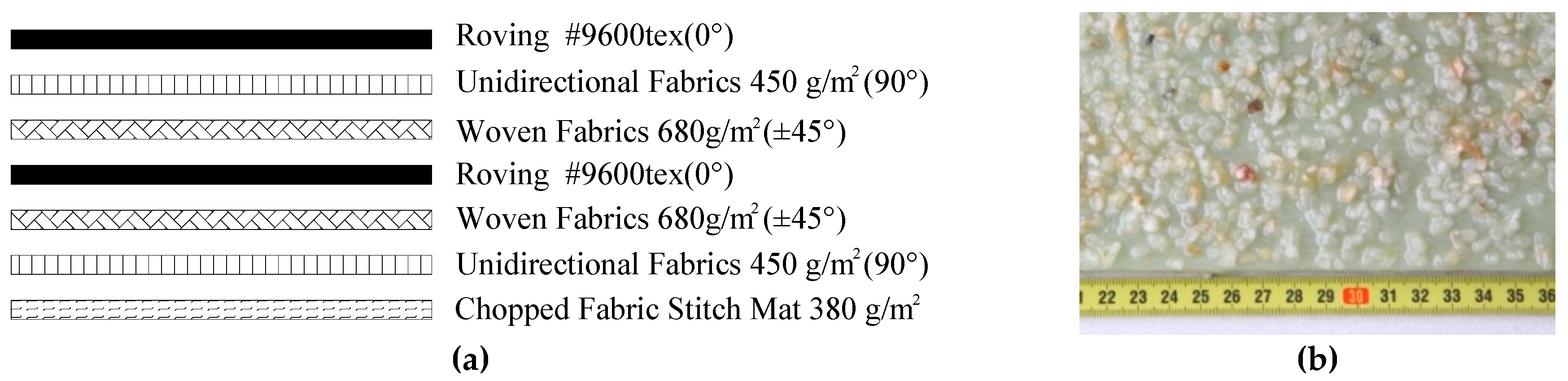
2.1. Materials
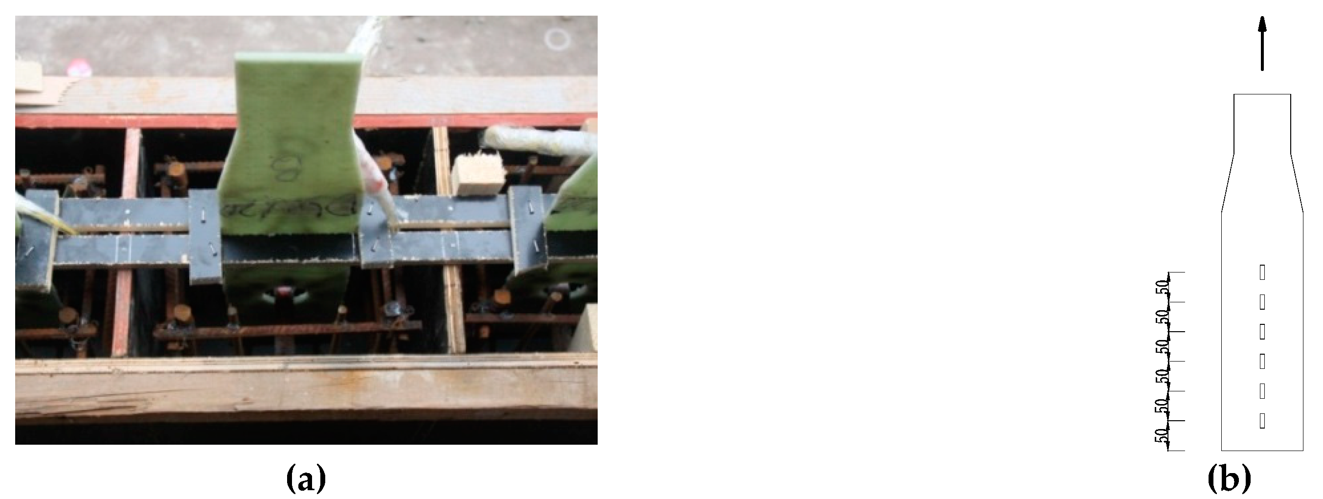
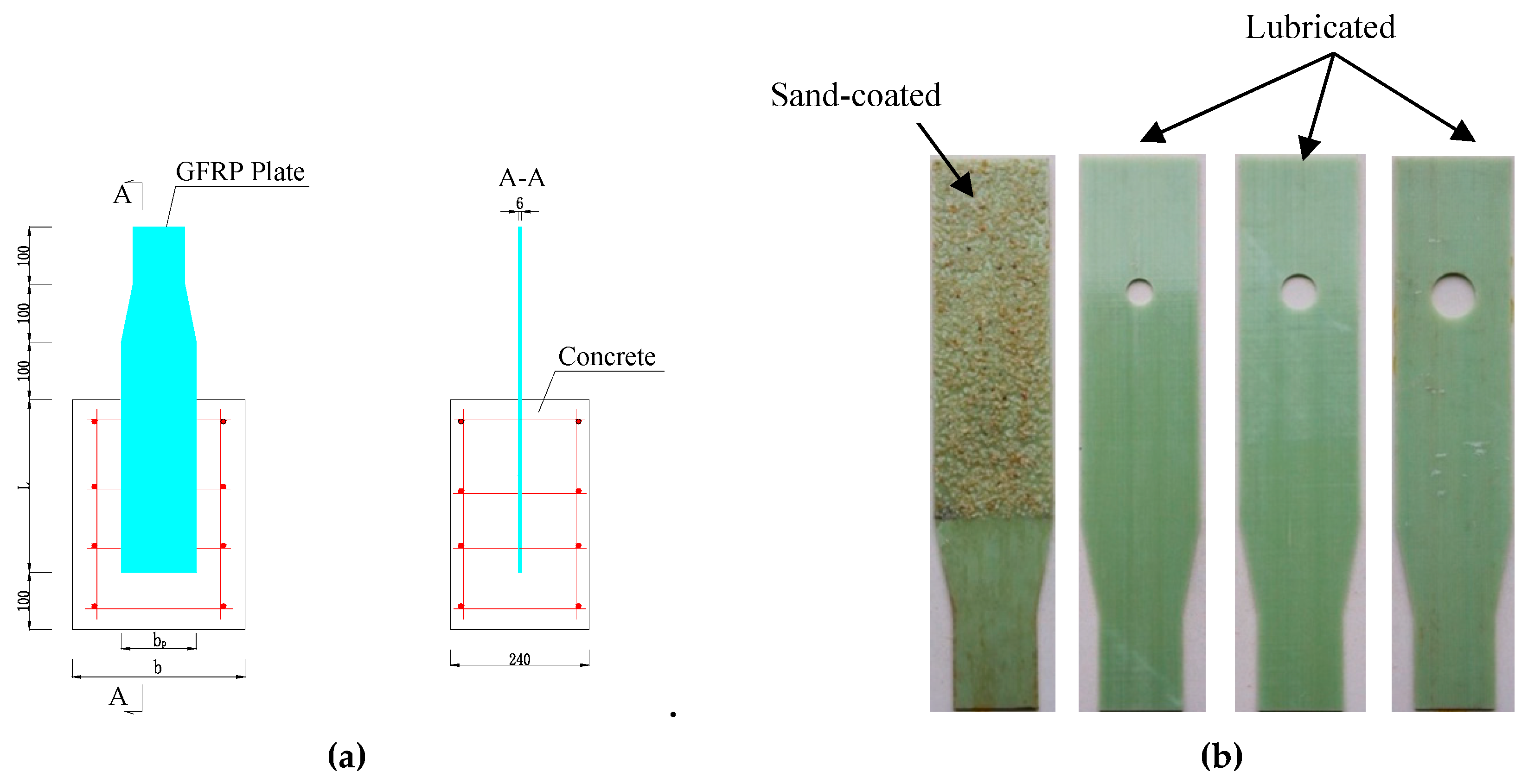
2.2. Fabrication of Pull-Out Specimens
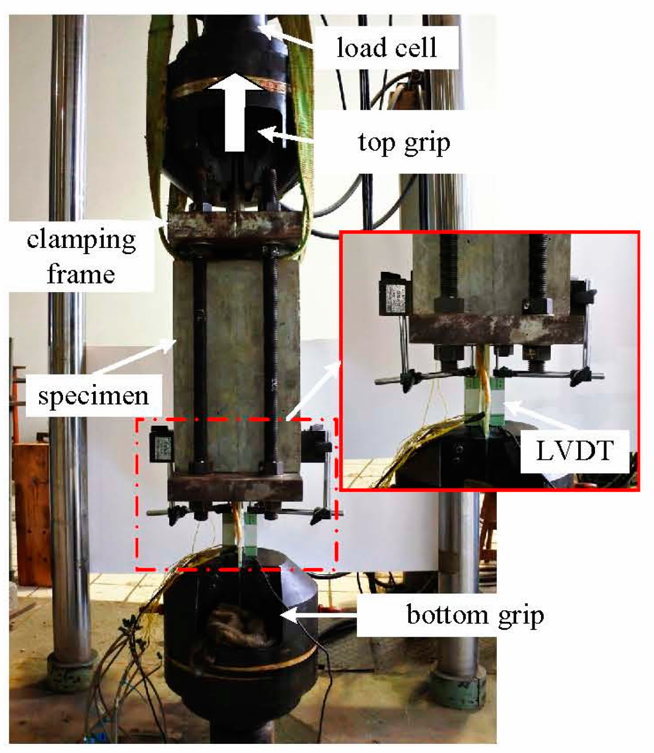
2.3. Pull-Out Test Setup
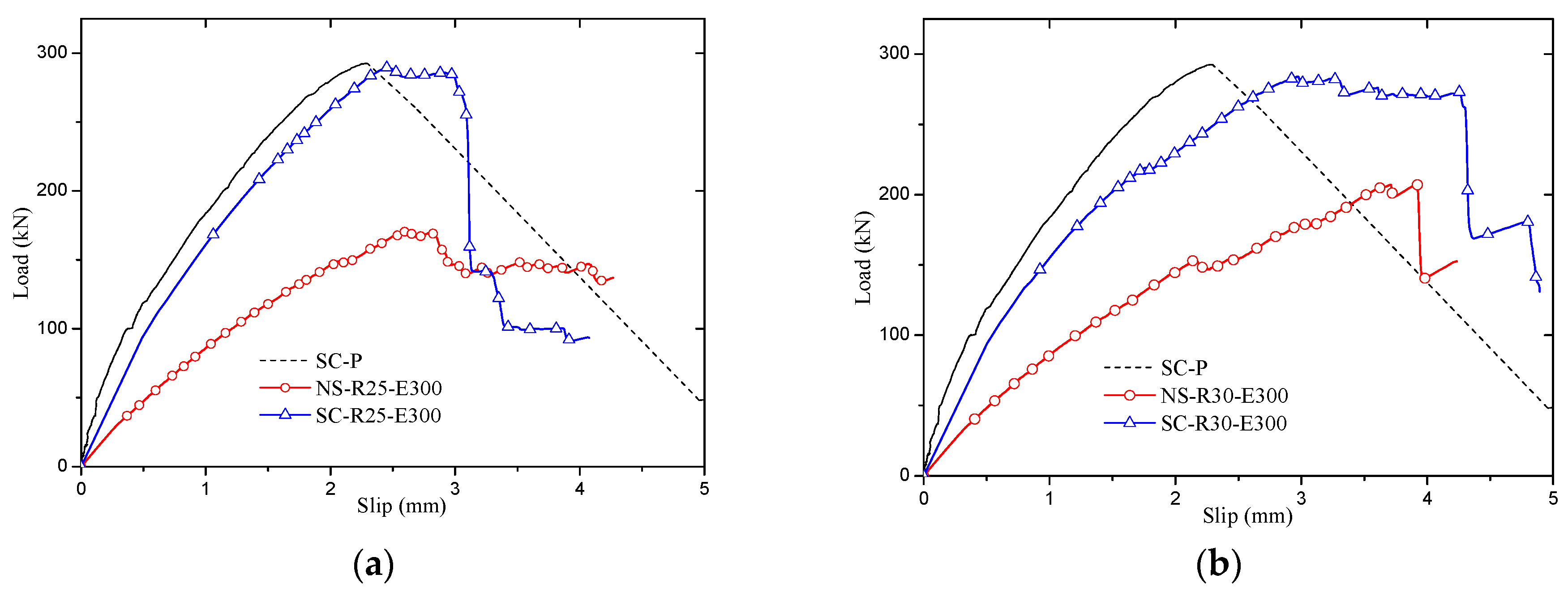
2.4. Pull-Out Test Results
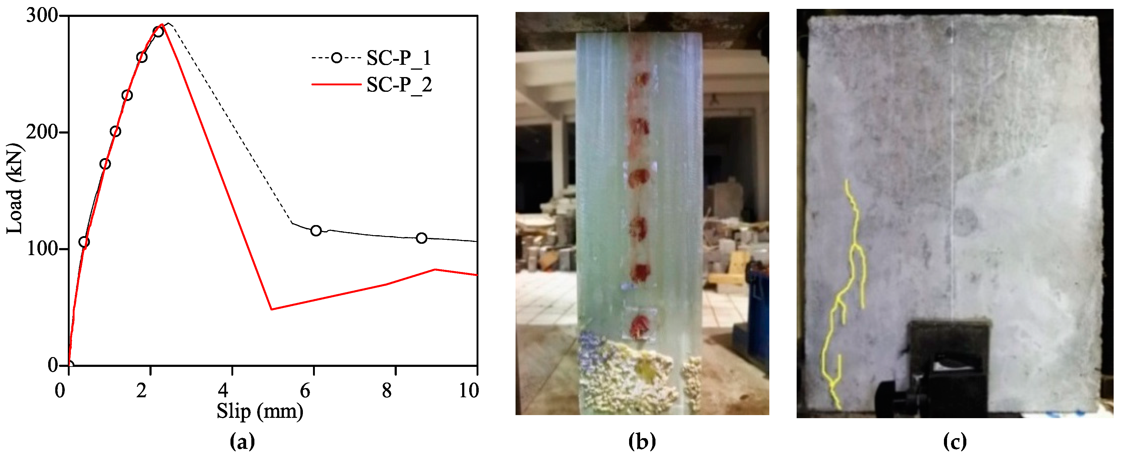
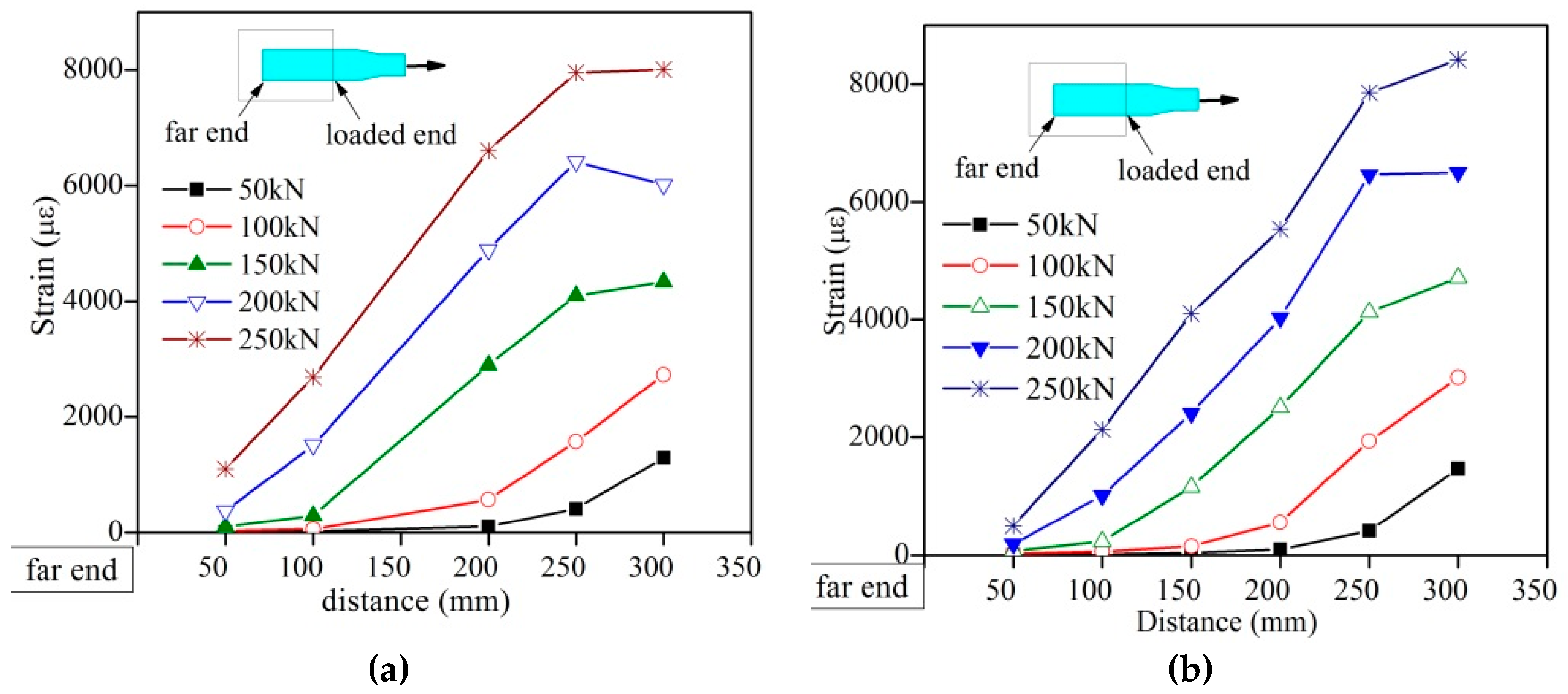
2.4.1. Sand-Coated Specimens Result
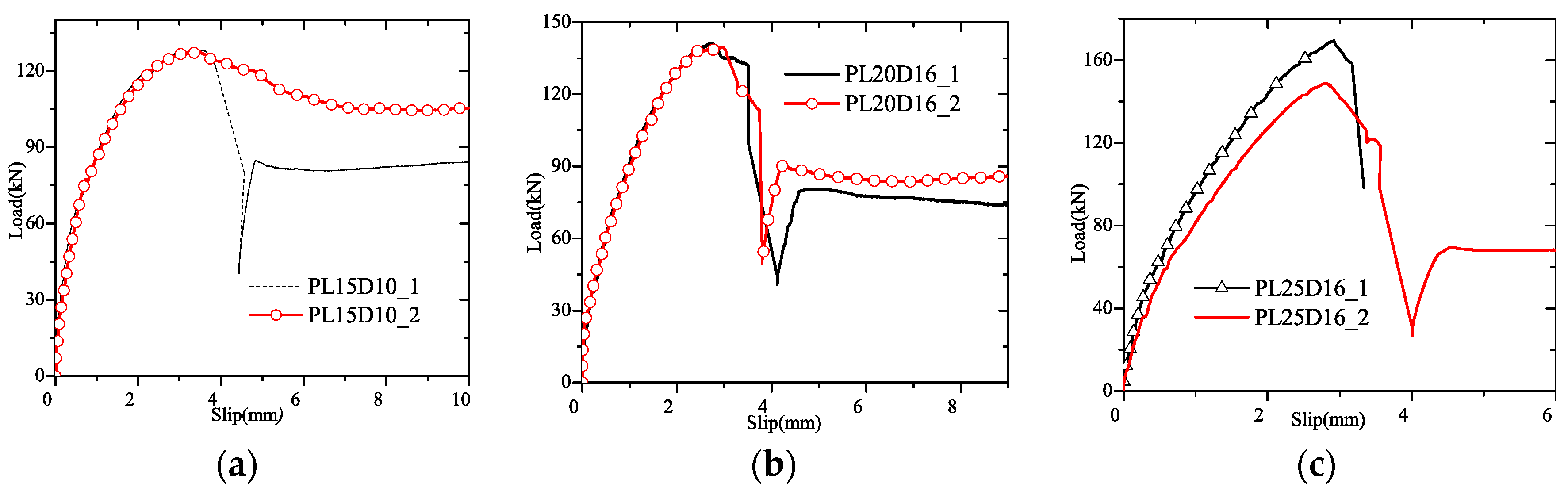
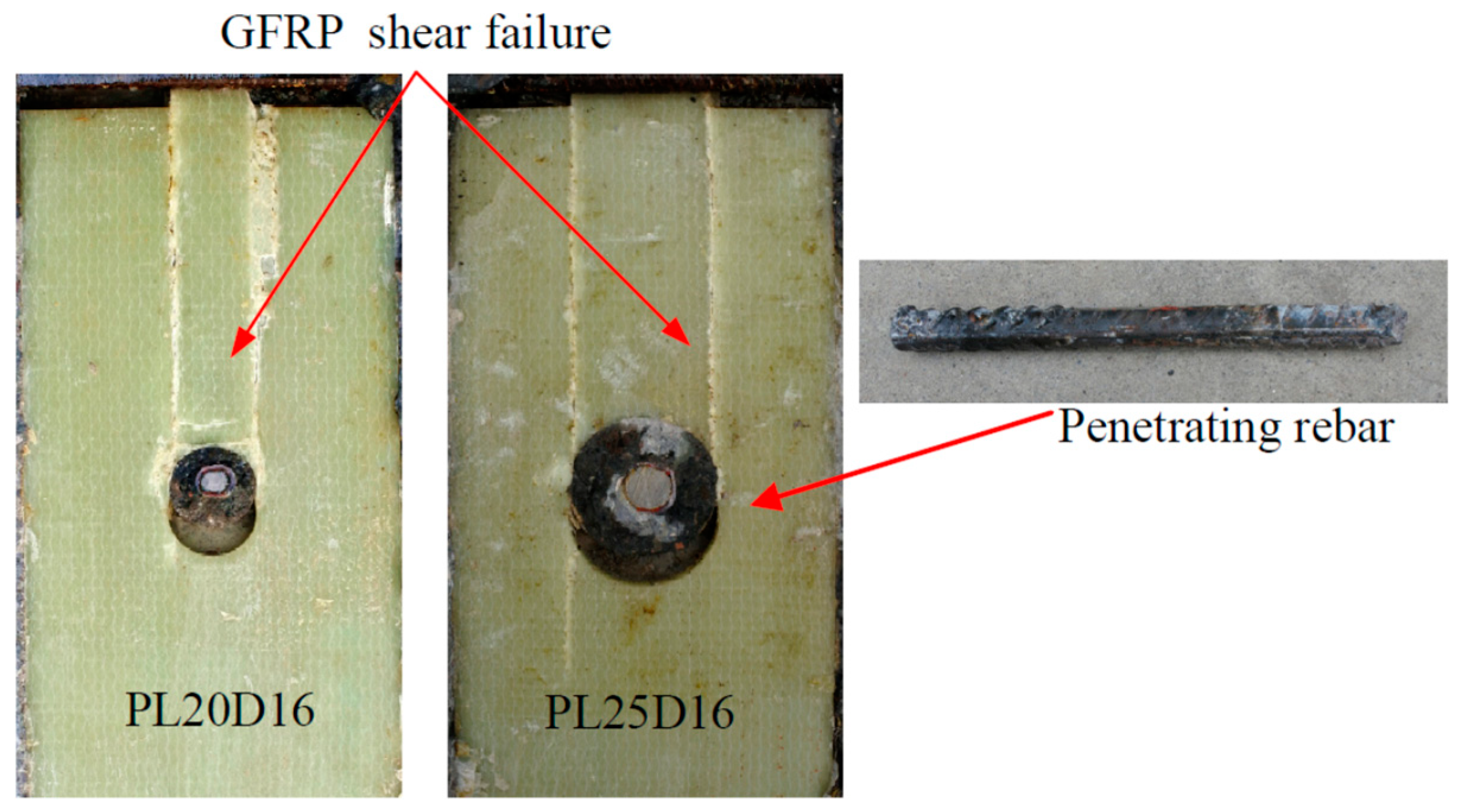
2.4.2. GPC Result
3. Sand-Coated GPC Numerical Analysis
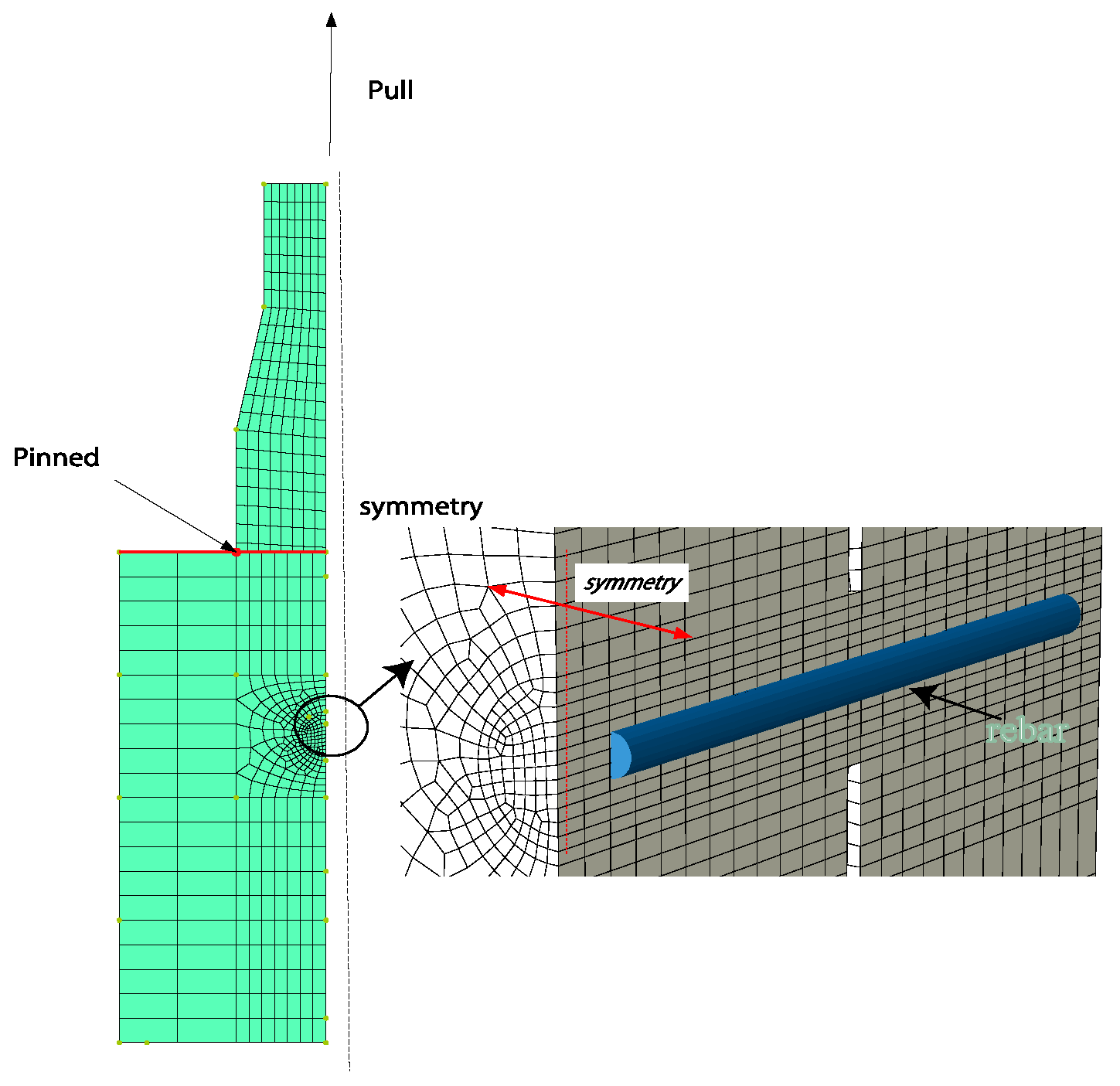
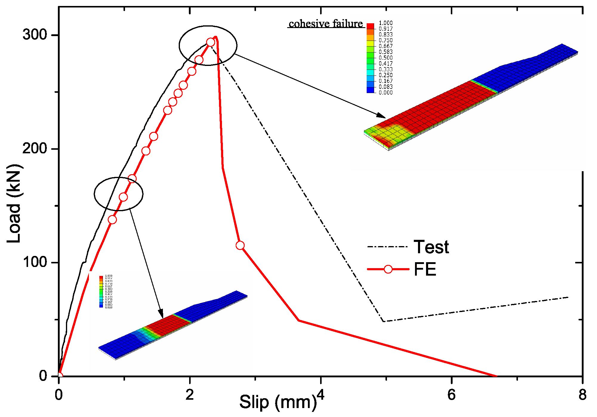
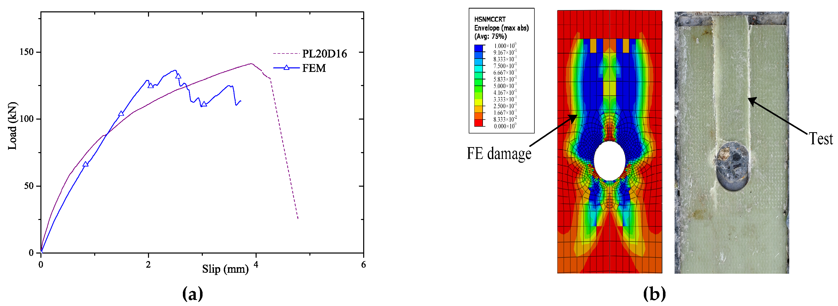
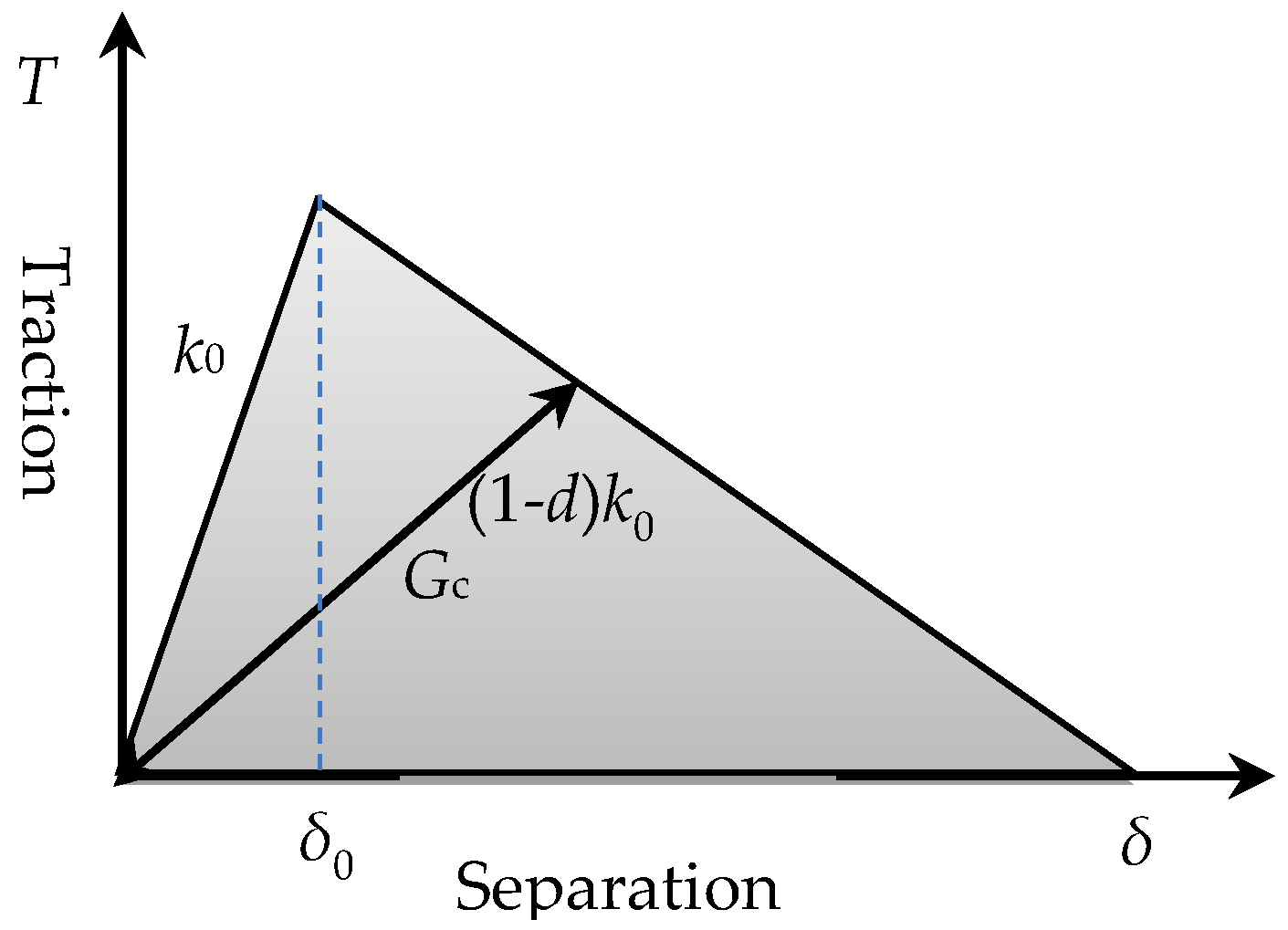
3.1. Description of the Model and Its Verification
3.2. Parametric Analysis
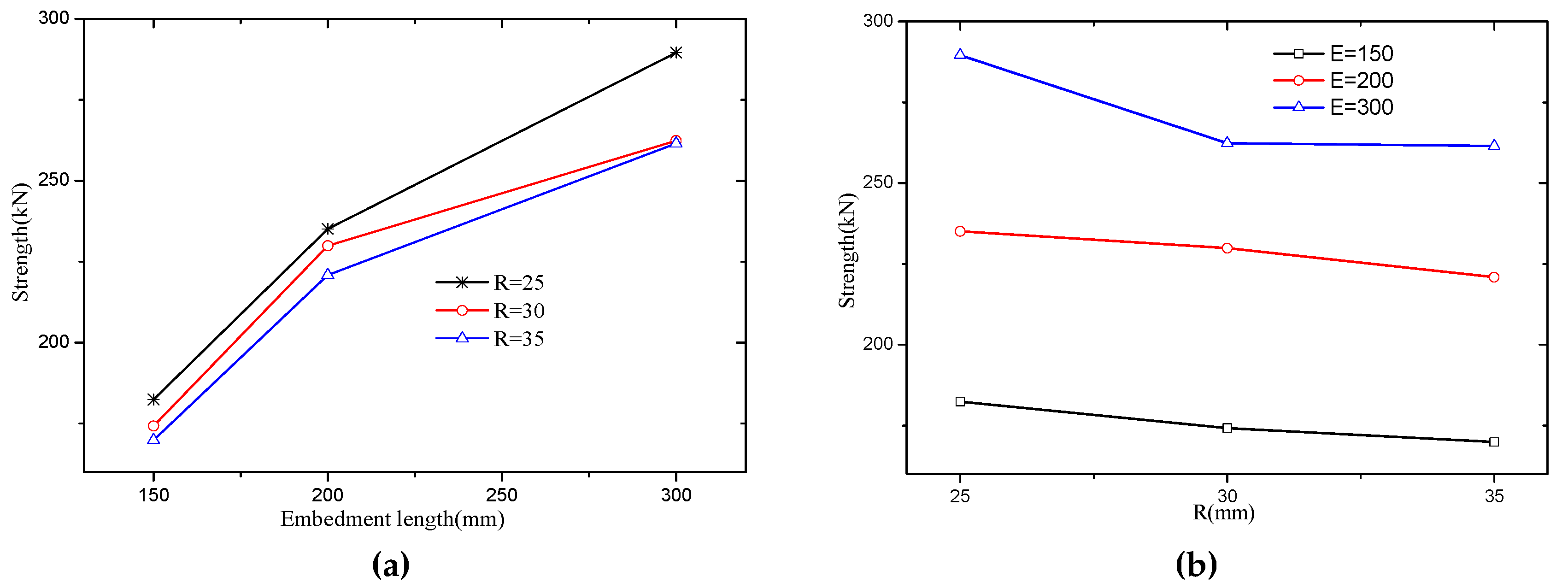
4. Parametric Analysis Result
5. Failure Mechanism and Empirical Equation
6. Conclusions
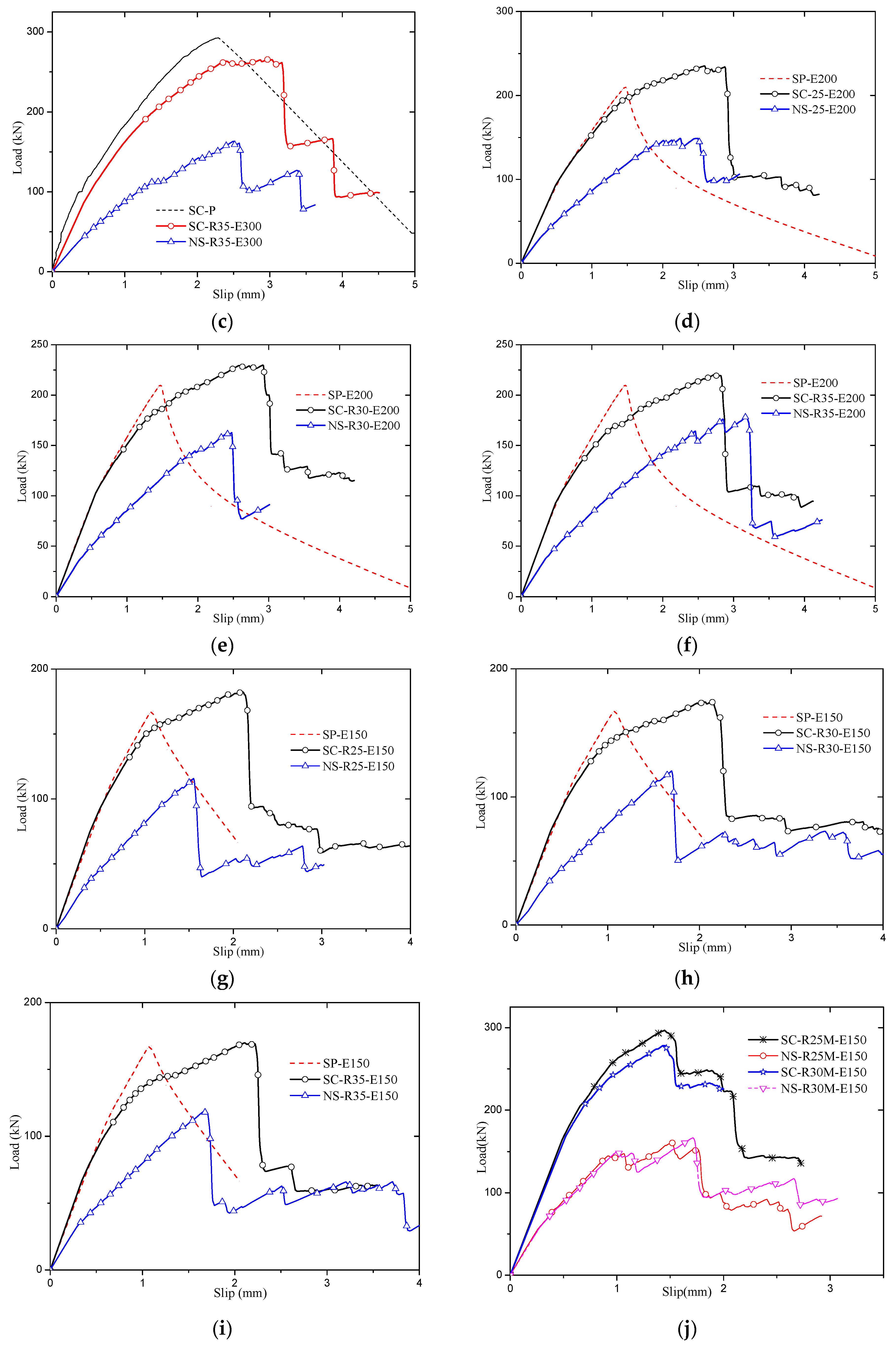
- The shear capacity of SCGPC is considerably larger than that of GPC. The stiffness of SCGPC is determined by the adhesion. The ductility of SCGPC is improved especially when the embedment length meets the effective bond length requirement, which results in the load-slip presenting a yield plateau similar as the steel material.
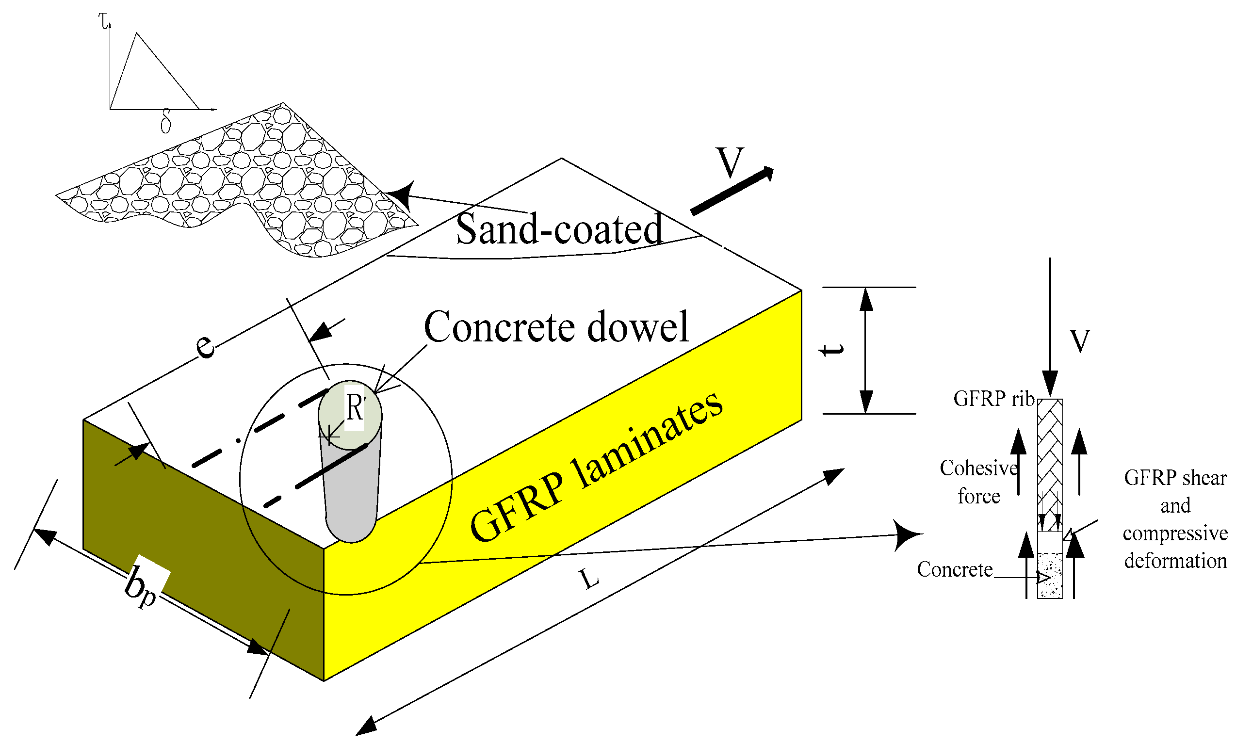
- SCGPC has the same characteristics as the sand-coated GFRP plate or rebar. Among the parameters affecting adhesion capacity, it is found that embedment length is the most dominant factor. When the embedment length is larger than effective bond length, the adhesion strength governs the strength of SCGPC; when the embedment length is less than effective bond length, the strength of SCGPC is determined by both the adhesion and GPC shear strength. In the meantime, SCGPC also has the nature of GPC; the shear failure mechanism of SCGPC has a close relation with the radius and the plate’s thickness same as GPC.
- An empirical equation is suggested to predict the shear strength of SCGPC. The equation solves the strength of SCGPC in two ranges according to the embedment length. The parametric analysis result agrees well with the suggested equation.
- SCGPC provides an effective alternative connection to GFRP-concrete composite structures. Compared to purely sand-coated GFRP plate, SCGPC has larger ductility. Compared to GPC, SCGPC’s shear strength is considerably improved by sand-coated surface treatment.
Author Contributions
Funding
Conflicts of Interest
References
- Keller, T.; Schaumann, E.; Vallée, T. Flexural behavior of a hybrid FRP and lightweight concrete sandwich bridge deck. Compos. A Appl. Sci. Manuf. 2007, 38, 879–889. [Google Scholar] [CrossRef]
- Nelson, M.; Fam, A. Structural GFRP permanent forms with T-shape ribs for bridge decks supported by precast concrete girders. J. Bridge Eng. 2012, 18, 813–826. [Google Scholar] [CrossRef]
- Xin, H.; Liu, Y.; Du, A. Thermal analysis on composite girder with hybrid GFRP-concrete deck. Steel Compos. Struct. 2015, 19, 1221–1236. [Google Scholar] [CrossRef]
- Kitane, Y.; Aref, A.J.; Lee, G.C. Static and fatigue testing of hybrid fiber-reinforced polymer-concrete bridge superstructure. J. Compos. Constr. 2004, 8, 182–190. [Google Scholar] [CrossRef]
- Feng, P.; Zhang, P.; Meng, X.; Ye, L. Mechanical analysis of stress distribution in a carbon fiber-reinforced polymer rod bonding anchor. Polymers. 2014, 6, 1129–1143. [Google Scholar] [CrossRef]
- Goyal, R.; Mukherjee, A.; Goyal, S. An investigation on bond between FRP stay-in-place formwork and concrete. Constr. Build. Mater. 2016, 113, 741–751. [Google Scholar] [CrossRef]
- Cho, K.; Park, S.Y.; Kim, S.T.; Cho, J.R.; Kim, B.S. Shear connection system and performance evaluation of FRP-concrete composite deck. KSCE J. Civ. Eng. 2010, 14, 855–865. [Google Scholar] [CrossRef]
- Woltman, G.; Tomlinson, D.; Fam, A. Investigation of various GFRP shear connectors for insulated precast concrete sandwich wall panels. J. Compos. Constr. 2013, 17, 711–721. [Google Scholar] [CrossRef]
- Chen, Y.; Davalos, J.F.; Ray, I.; Kim, H.Y. Accelerated aging tests for evaluations of durability performance of FRP reinforcing bars for concrete structures. Compos. Struct. 2007, 78, 101–111. [Google Scholar] [CrossRef]
- Liu, Y.; Xiong, Z.; Feng, Y.; Jiang, L. Concrete-filled rectangular hollow section X joint with Perfobond Leister rib structural performance study: Ultimate and fatigue experimental Investigation. Steel Compos. Struct. 2017, 24, 455–465. [Google Scholar] [CrossRef]
- Xiong, Z.; Li, J.; Wang, S.; Liu, Y.; Xin, H. Concrete filled tubular arch modified-VFT bridge and its LLSI analysis. In Proceedings of the 2017 3rd International Forum on Energy, Environment Science and Materials (IFEESM 2017), Shenzhen, China, 25–26 November 2017. [Google Scholar] [CrossRef]
- Zuo, Y.; Liu, Y.; He, J. Experimental investigation on hybrid GFRP-concrete decks with T-shaped perforated ribs subjected to negative moment. Constr. Build. Mater. 2018, 158, 728–741. [Google Scholar] [CrossRef]
- Chen, J.F.; Teng, J.G. Anchorage strength models for FRP and steel plates bonded to concrete. J. Struct. Eng. 2001, 127, 784–791. [Google Scholar] [CrossRef]
- Seracino, R.; Raizal Saifulnaz, M.R.; Oehlers, D.J. Generic debonding resistance of EB and NSM plate-to-concrete joints. J. Compos. Constr. 2007, 11, 62–70. [Google Scholar] [CrossRef]
- Bilotta, A.; Ceroni, F.; Di Ludovico, M.; Nigro, E.; Pecce, M.; Manfredi, G. Bond efficiency of EBR and NSM FRP systems for strengthening concrete members. J. Compos. Constr. 2011, 15, 757–772. [Google Scholar] [CrossRef]
- Kalupahana, W. Anchorage and Bond Behaviour of near Surface Mounted Fibre Reinforced Polymer Bars. Ph.D. Thesis, University of Bath, Bath, UK, 2009. [Google Scholar]
- Seracino, R.; Jones, N.M.; Ali, M.S.; Page, M.W.; Oehlers, D.J. Bond strength of near-surface mounted FRP strip-to-concrete joints. J. Compos. Constr. 2007, 11, 401–409. [Google Scholar] [CrossRef]
- Naser, M.; Hawileh, R.; Abdalla, J.A.; Al-Tamimi, A. Bond behavior of CFRP cured laminates: Experimental and numerical investigation. J. Eng. Mater. Technol.-Trans. ASME. 2012, 134, 021002. [Google Scholar] [CrossRef]
- Budhe, S.; Banea, M.D.; De Barros, S.; Da Silva, L.F.M. An updated review of adhesively bonded joints in composite materials. Int. J. Adhes. Adhes. 2017, 72, 30–42. [Google Scholar] [CrossRef]
- Chen, D.; El-Hacha, R. Cohesive fracture study of a bonded coarse silica sand aggregate bond interface subjected to mixed-mode bending conditions. Polymers 2014, 6, 12–38. [Google Scholar] [CrossRef]
- Tekle, B.H.; Khennane, A.; Kayali, O. Bond Properties of Sand-Coated GFRP Bars with Fly Ash–Based Geopolymer Concrete. J. Compos. Constr. 2016, 20, 04016025. [Google Scholar] [CrossRef]
- Cho, J.R.; Cho, K.; Park, S.Y.; Kim, S.T.; Kim, B.S. Bond characteristics of coarse sand coated interface between stay-in-place fibre-reinforced polymer formwork and concrete based on shear and tension tests. Can. J. Civ. Eng. 2010, 37, 706–718. [Google Scholar] [CrossRef]
- Iovinella, I.; Prota, A.; Mazzotti, C. Influence of surface roughness on the bond of FRP laminates to concrete. Constr. Build. Mater. 2013, 40, 533–542. [Google Scholar] [CrossRef]
- Cho, J.R.; Park, S.Y.; Cho, K.; Kim, S.T.; Kim, B.S. Pull-out test and discrete spring model of fibre-reinforced polymer perfobond rib shear connector. Can. J. Civ. Eng. 2012, 39, 1311–1320. [Google Scholar] [CrossRef]
- Zou, X.; Feng, P.; Wang, J. Perforated FRP ribs for shear connecting of FRP-concrete hybrid beams/decks. Compos. Struct. 2016, 152, 267–276. [Google Scholar] [CrossRef]
- Xiong, Z.; Liu, Y.; Zuo, Y.; Xin, H. Experimental Evaluation of Shear Behavior of Pultruded GFRP Perforated Connectors Embedded in Concrete. Compos. Struct. 2019, 222, 110938. [Google Scholar] [CrossRef]
- Henriques, J.; Da Silva, L.S.; Valente, I.B. Numerical modeling of composite beam to reinforced concrete wall joints: Part I: Calibration of joint components. Eng. Struct. 2013, 52, 747–761. [Google Scholar] [CrossRef]
- Hashin, Z. Failure criteria for unidirectional fiber composites. J. Appl. Mech. 1980, 47, 329–334. [Google Scholar] [CrossRef]
- Xin, H.; Mosallam, A.; Liu, Y.; Wang, C.; Zhang, Y. Analytical and experimental evaluation of flexural behavior of FRP pultruded composite profiles for bridge deck structural design. Constr. Build. Mater. 2017, 150, 123–149. [Google Scholar] [CrossRef]
- Zuo, Y.; Mosallam, A.; Xin, H.; Liu, Y.; He, J. Flexural performance of a hybrid GFRP-concrete bridge deck with composite T-shaped perforated rib connectors. Compos. Struct. 2018, 194, 263–278. [Google Scholar] [CrossRef]
- FIB Bulletin. No.65. Model Code 2010, vol. 1; FIB Bulletins: Lausanne, Switzerland, 2012. [Google Scholar]
- Jankowiak, T.; Lodygowski, T. Identification of parameters of concrete damage plasticity constitutive model. Found. Civ. Environ. Eng. 2005, 6, 53–69. [Google Scholar]


| Property | Value | Unit | Standard Deviation |
|---|---|---|---|
| Longitudinal tensile strength | 430.0 | MPa | 31.3 |
| Longitudinal tensile modulus | 45.5 | GPa | 4.5 |
| Longitudinal compressive strength | 491.4 | MPa | 54.7 |
| Transverse tensile strength | 67.6 | MPa | 2.8 |
| Transverse tensile modulus | 21.7 | GPa | 1.9 |
| Transverse compressive strength | 166.7 | MPa | 16.9 |
| shear strength | 58.4 | MPa | 10.1 |
| shear modulus | 9.8 | GPa | 0.9 |
| Specimens NO. | Surface Treatment | R | b | bp | L | Diameter of Penetrating Rebars |
|---|---|---|---|---|---|---|
| SC-P | Sand-coated | - | 300 | 130 | 300 | - |
| PL15D10 | Lubricated | 15 | 300 | 10 | ||
| PL20D16 | Lubricated | 20 | 300 | 16 | ||
| PL25D16 | Lubricated | 25 | 300 | 16 |
| Item | Value |
|---|---|
| XT | 1335.2 |
| YT | 955.4 |
| XC | 43.8 |
| YC | 155.8 |
| SL | 76.0 |
| ST | 76.0 |
| Ply | Angle (°) | Thickness (mm) |
|---|---|---|
| 1 | 0 | 1.7 |
| 2 | 90 | 0.28 |
| 3 | ±45 | 0.8 |
| 4 | 0 | 1.7 |
| 5 | ±45 | 0.8 |
| 6 | 90 | 0.28 |
| 7 | ±45 | 0.44 |
| Specimens NO. | Surface Treatment | R | Embedding Length | Multi-Hole |
|---|---|---|---|---|
| NS-R25-E300 | None | 25 | 300 | |
| NS-R30-E300 | None | 30 | 300 | |
| NS-R35-E300 | None | 35 | 300 | |
| SC-R25-E300 | Sand-coated | 25 | 300 | |
| SC-R30-E300 | Sand-coated | 30 | 300 | |
| SC-R35-E300 | Sand-coated | 35 | 300 | |
| NS-R25-E200 | None | 25 | 200 | |
| NS-R30-E200 | None | 30 | 200 | |
| NS-R35-E200 | None | 35 | 200 | |
| SP-E200 | Sand-coated | - | 200 | |
| SC-R25-E200 | Sand-coated | 25 | 200 | |
| SC-R30-E200 | Sand-coated | 30 | 200 | |
| SC-R35-E200 | Sand-coated | 35 | 200 | |
| NS-R25-E150 | None | 25 | 150 | |
| NS-R30-E150 | None | 30 | 150 | |
| NS-R35-E150 | None | 35 | 150 | |
| SP-E150 | Sand-coated | - | 150 | |
| SC-R25-E150 | Sand-coated | 25 | 150 | |
| SC-R30-E150 | Sand-coated | 30 | 150 | |
| SC-R35-E150 | Sand-coated | 35 | 150 | |
| SC-R25M-E150 | Sand-coated | 25 | 150 | Two holes |
| SC-R30M-E150 | Sand-coated | 30 | 150 | Tow holes |
| Specimens NO. | R(mm) | Embedment Length, L(mm) | Strength by FE (kN) | Equations (10) and (11) (kN) | Deviation |
|---|---|---|---|---|---|
| SC-R25-E300 | 25 | 300 | 289.6 | 272.7 | −0.058 |
| SC-R30-E300 | 30 | 300 | 262.4 | 266.3 | 0.015 |
| SC-R35-E300 | 35 | 300 | 261.5 | 258.8 | −0.010 |
| SC-R25-E200 | 25 | 200 | 235.1 | 193.7 | −0.176 |
| SC-R30-E200 | 30 | 200 | 229.9 | 191.6 | −0.166 |
| SC-R35-E200 | 35 | 200 | 220.9 | 186.4 | −0.156 |
| SC-R25-E150 | 25 | 150 | 182.4 | 174.2 | −0.045 |
| SC-R30-E150 | 30 | 150 | 174.2 | 171.9 | −0.013 |
| SC-R35-E150 | 35 | 150 | 169.9 | 167.3 | −0.016 |
© 2019 by the authors. Licensee MDPI, Basel, Switzerland. This article is an open access article distributed under the terms and conditions of the Creative Commons Attribution (CC BY) license (http://creativecommons.org/licenses/by/4.0/).
Share and Cite
Xiong, Z.; Liu, Y.; Zuo, Y.; Xin, H. Shear Performance Assessment of Sand-Coated GFRP Perforated Connectors Embedded in Concrete. Materials 2019, 12, 1906. https://doi.org/10.3390/ma12121906
Xiong Z, Liu Y, Zuo Y, Xin H. Shear Performance Assessment of Sand-Coated GFRP Perforated Connectors Embedded in Concrete. Materials. 2019; 12(12):1906. https://doi.org/10.3390/ma12121906
Chicago/Turabian StyleXiong, Zhihua, Yuqing Liu, Yize Zuo, and Haohui Xin. 2019. "Shear Performance Assessment of Sand-Coated GFRP Perforated Connectors Embedded in Concrete" Materials 12, no. 12: 1906. https://doi.org/10.3390/ma12121906
APA StyleXiong, Z., Liu, Y., Zuo, Y., & Xin, H. (2019). Shear Performance Assessment of Sand-Coated GFRP Perforated Connectors Embedded in Concrete. Materials, 12(12), 1906. https://doi.org/10.3390/ma12121906