Investigation of Cutting Temperature during Turning Inconel 718 with (Ti,Al)N PVD Coated Cemented Carbide Tools


Abstract
:1. Introduction
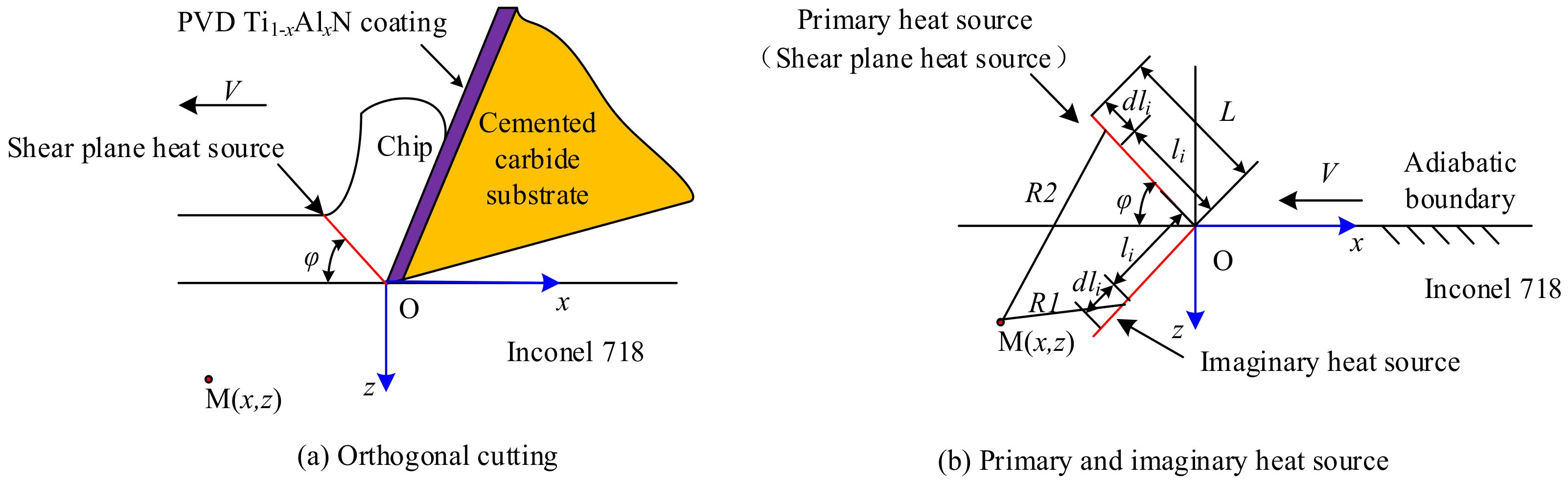
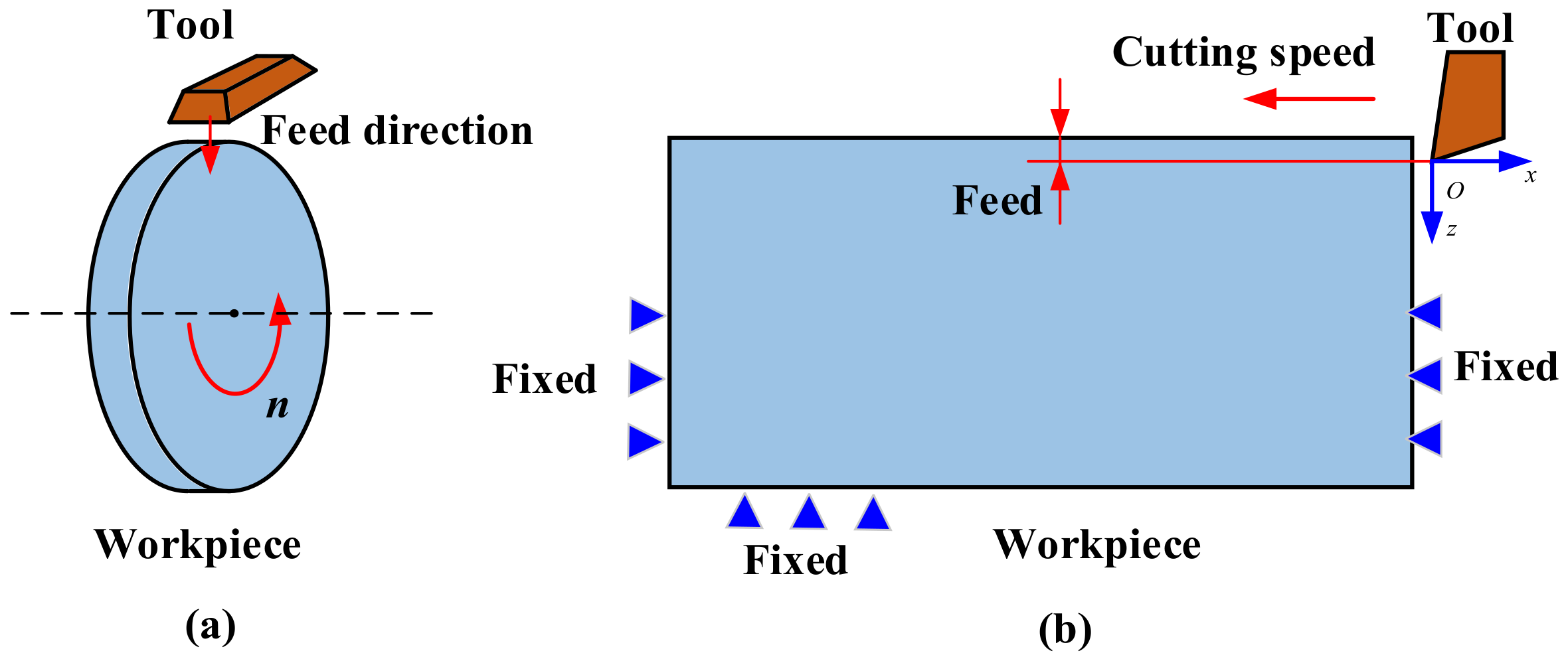
2. Mathematical Analysis Model of Cutting Temperature in Turning Inconel 718 by PVD Ti1−xAlxN Coated Tools
3. Experimental Procedure
3.1. Characterization of Surface and Microstructure for PVD Ti1−xAlxN Coatings
3.2. Characterization of Mechanical Properties for PVD Ti1−xAlxN Coated Tools
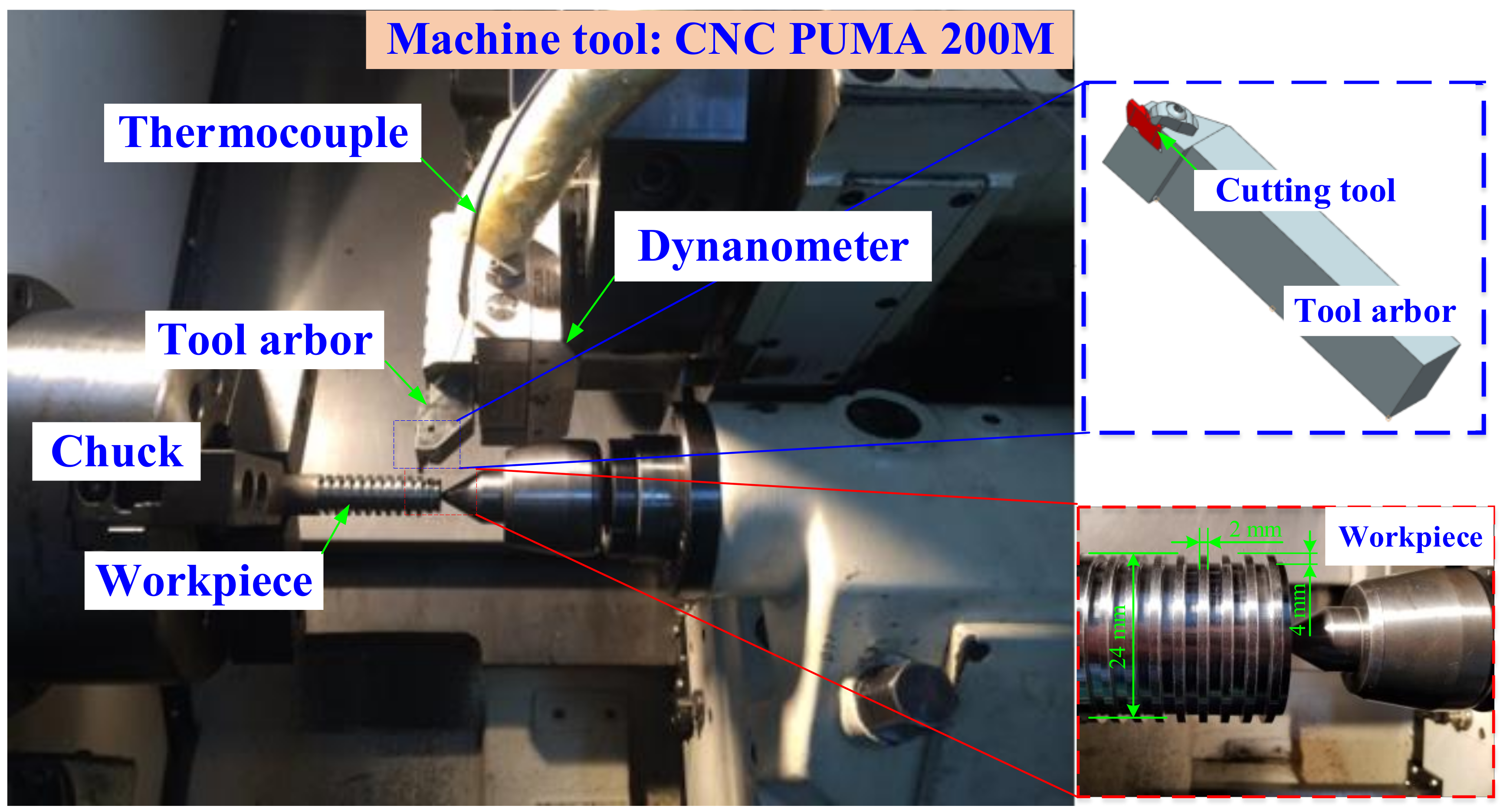
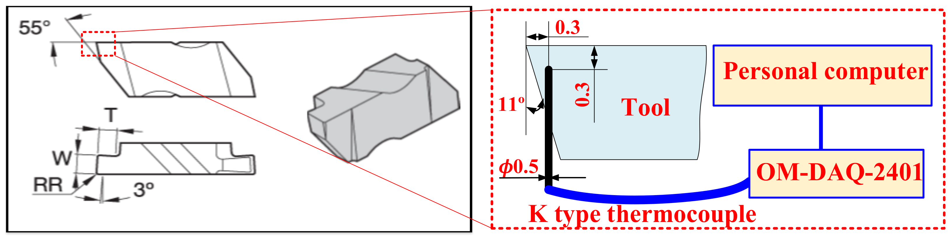
3.3. Cutting Experiment Procedure
4. Finite Element Simulation of Cutting Temperature in Turning Inconel 718 with PVD Ti1−xAlxN Coated Tools
5. Results and Discussion
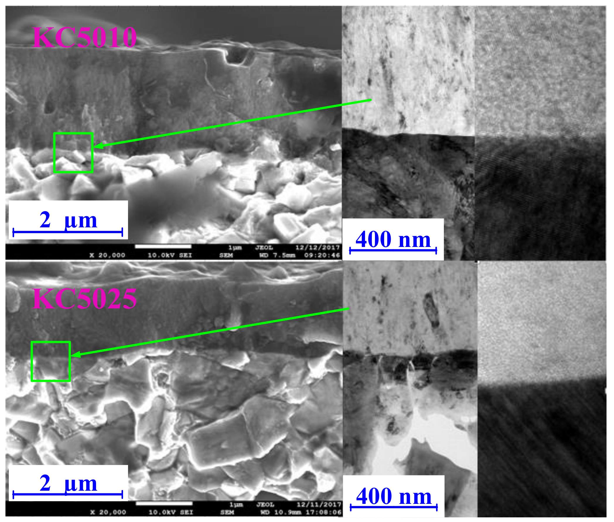
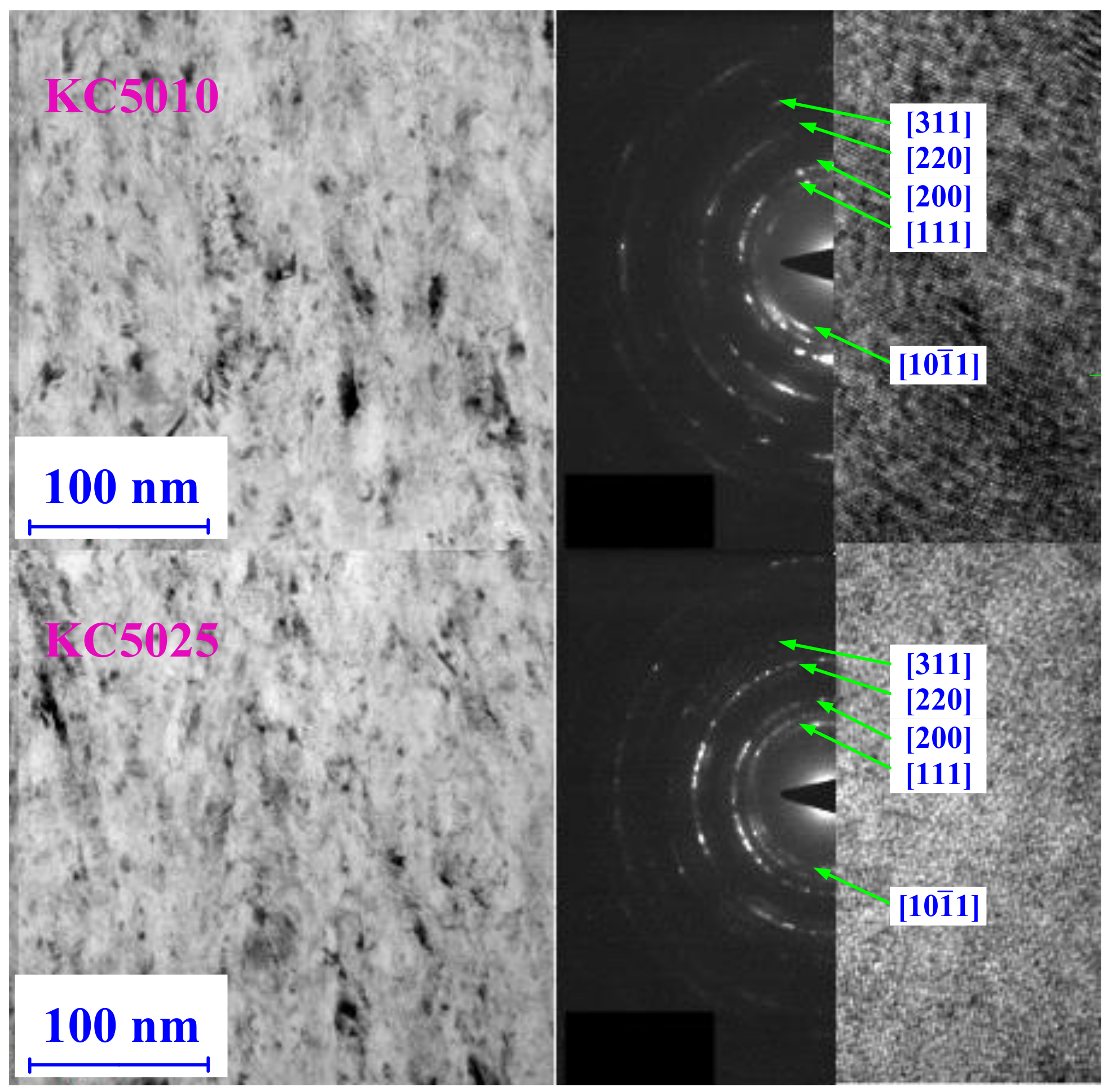
5.1. Microstructure of PVD Ti1−xAlxN Coatings
5.2. Mechanical and Thermo-Physical Properties of PVD Ti1−xAlxN Coatings
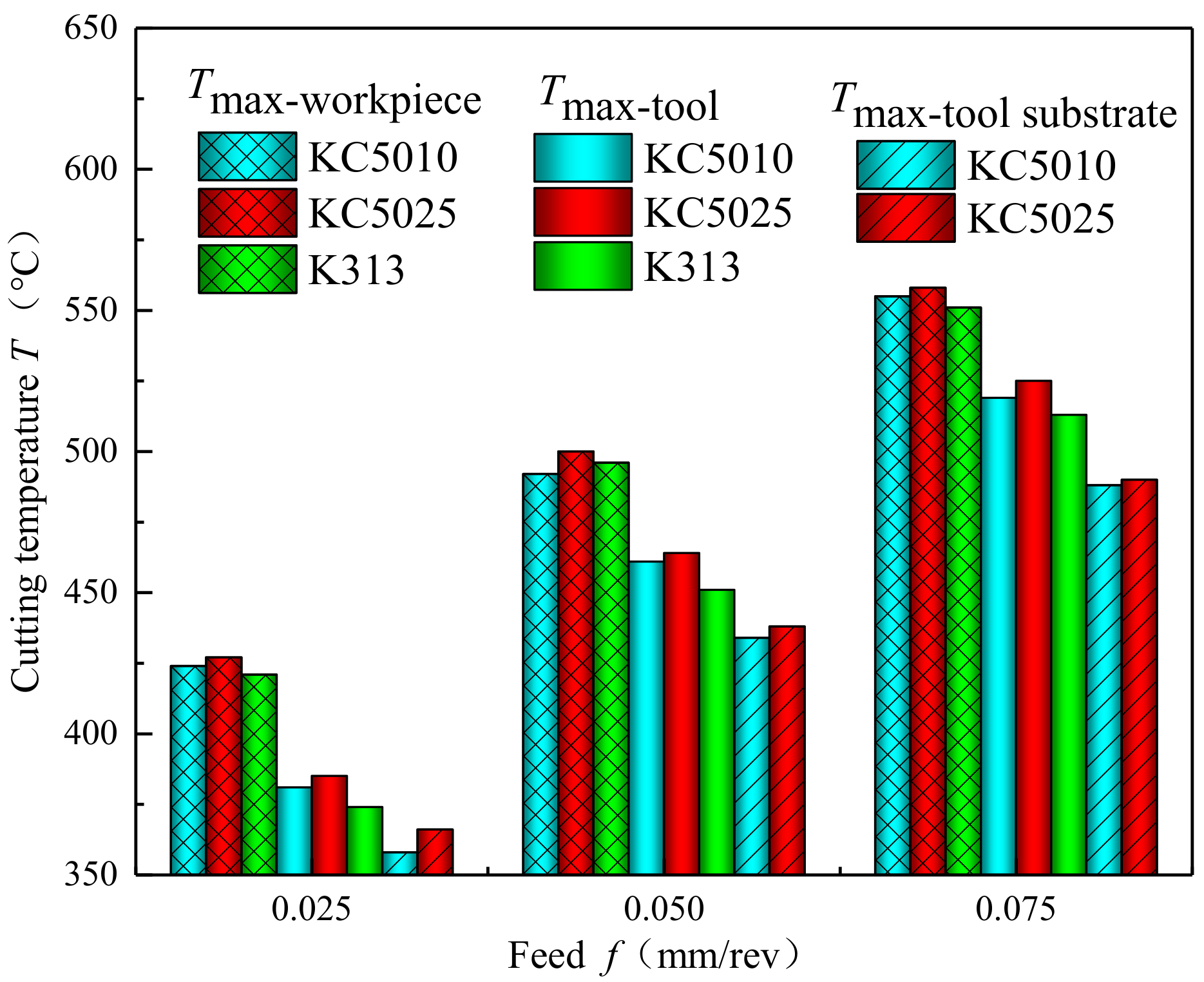
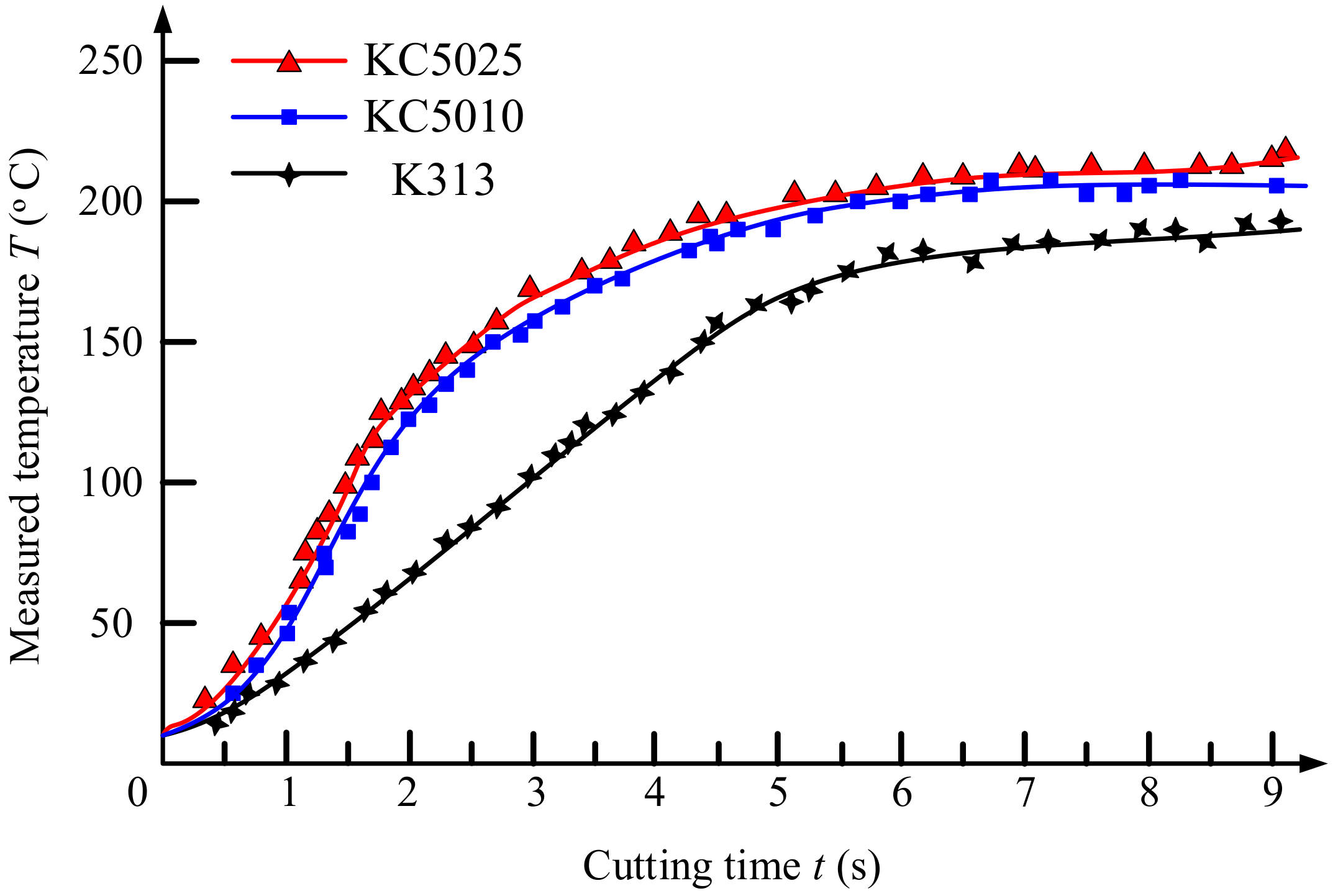
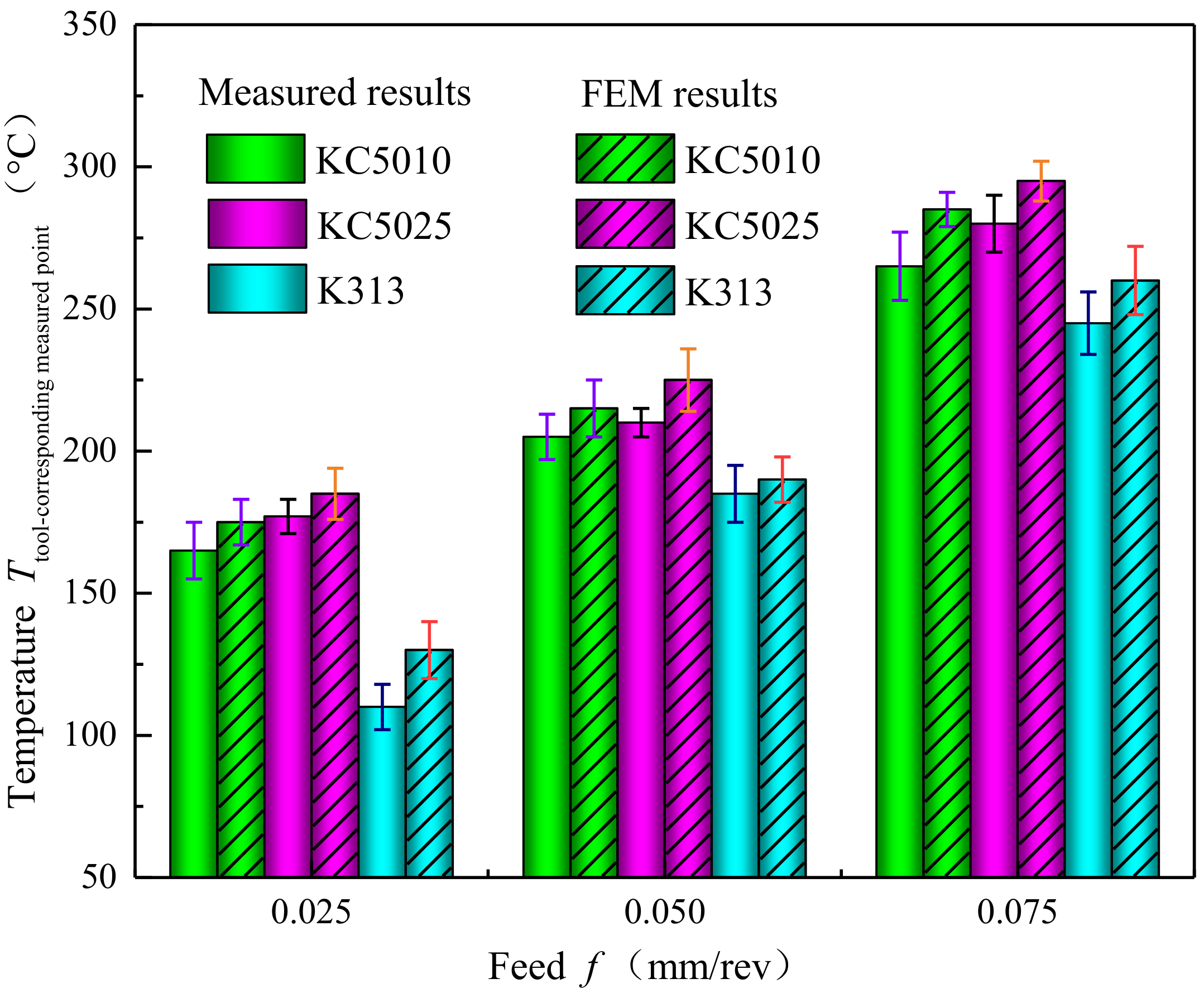
5.3. Influences of PVD Ti1−xAlxN Coated Tools on Cutting Temperature
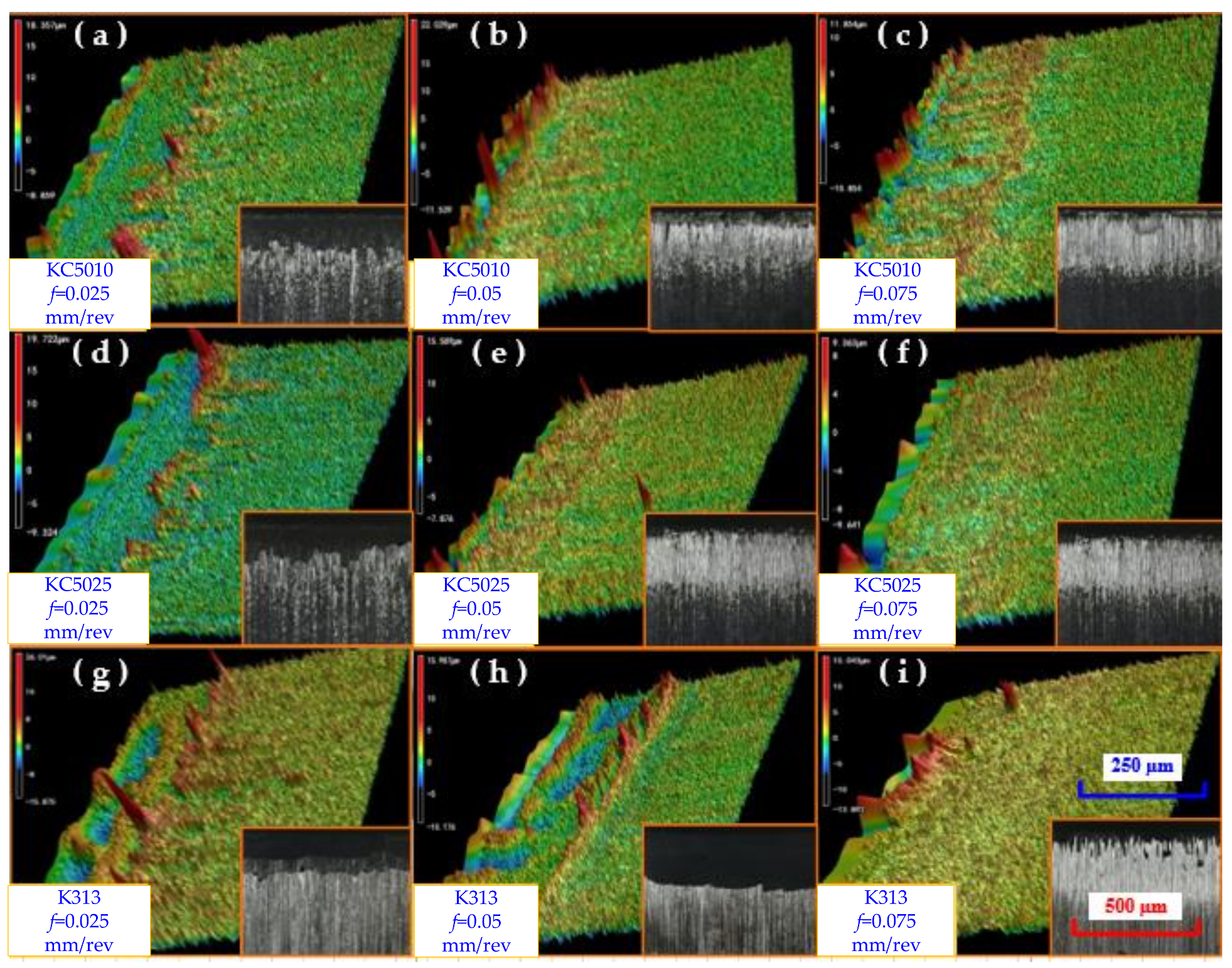
5.4. Influences of PVD Ti1−xAlxN Coating on the Surface Topographies of the Tool Rake Faces
6. Conclusions
- (1)
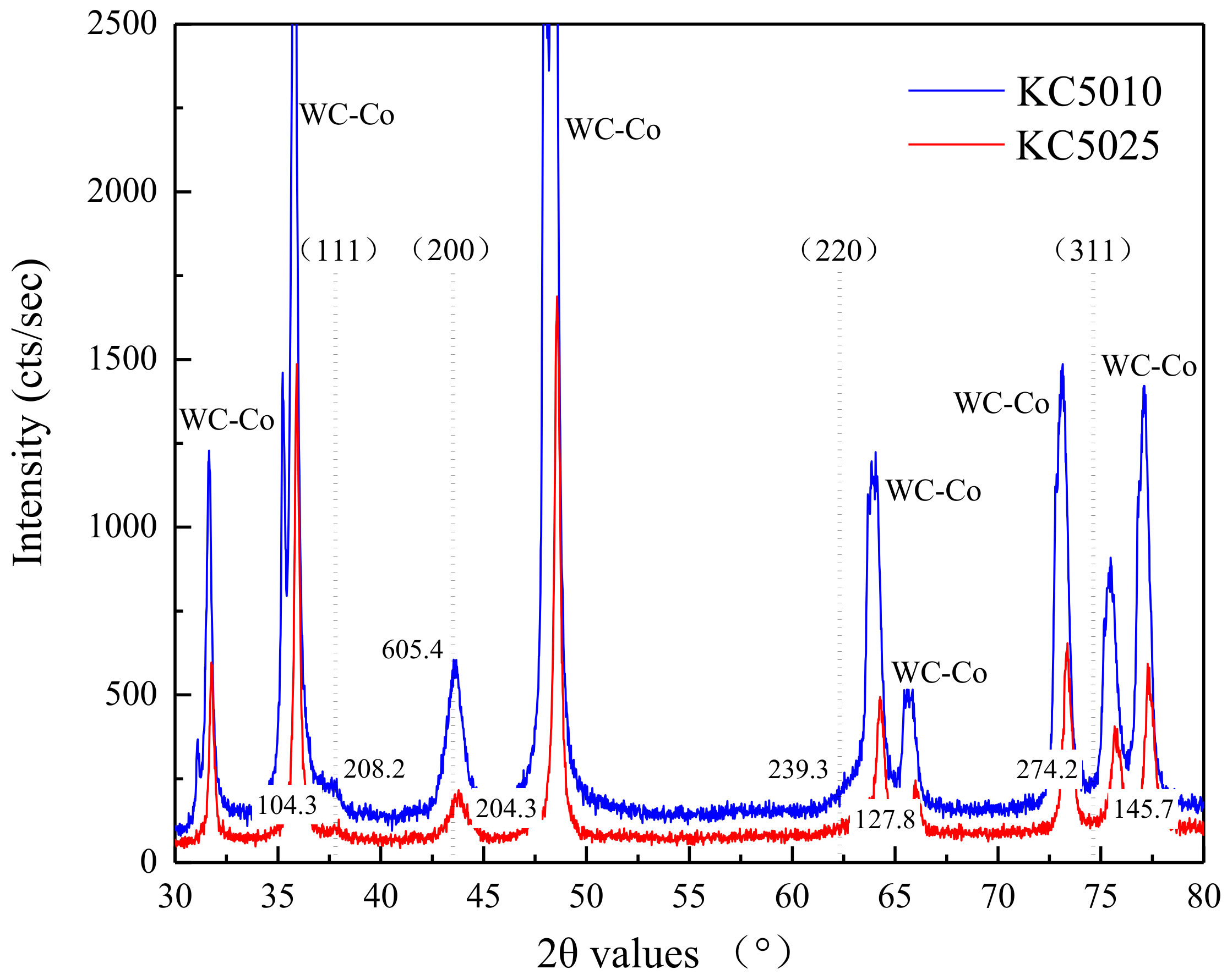
- The grain preferred orientations (111) and (200) of PVD Ti0.41Al0.59N coating were more evident compared with that of PVD Ti0.55Al0.45N coating. The epitaxy growth of TiAlN crystals did not exist in PVD Ti1−xAlxN coated cemented carbide tool for low deposition temperature. PVD Ti0.41Al0.59N coating had better crystallinity than PVD Ti0.55Al0.45N coating.
- (2)
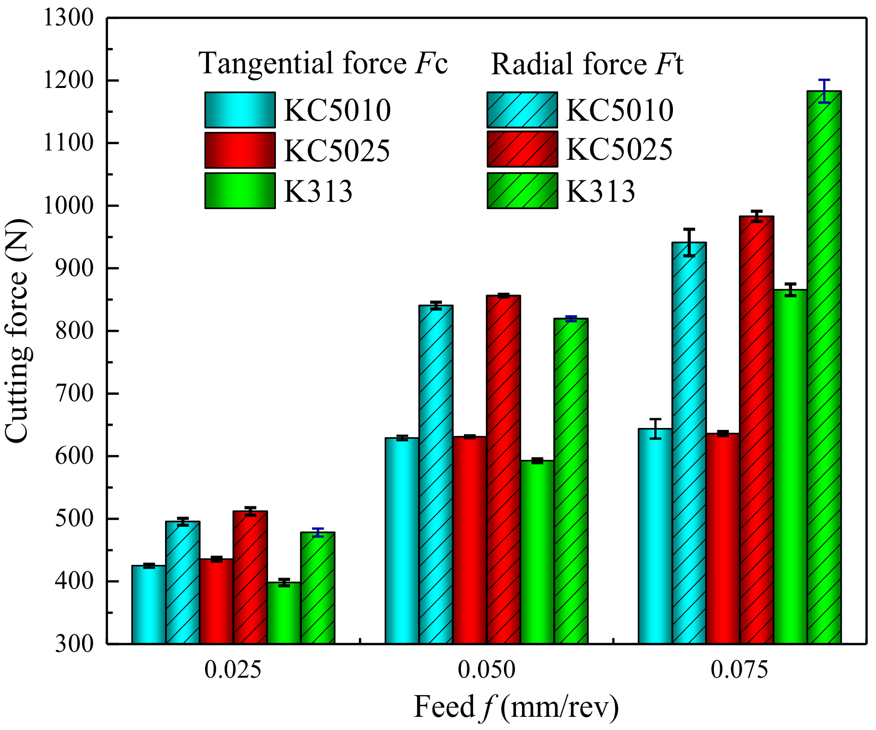
- The pinning effect of coating increased with the increase of Al concentration, which can help to decrease the friction coefficient between cutting tool and Inconel 718 materials. Compared with PVD Ti0.55Al0.45N coated tools, PVD Ti0.41Al0.59N coated tools increased the coating hardness, critical loads and thermal conductivity.
- (3)
- Compared with PVD Ti0.55Al0.45N coated tools, PVD Ti0.41Al0.59N coated tools increased the maximum temperature of the workpiece and the maximum temperature of the coated tool compared with the uncoated tool. PVD Ti0.41Al0.59N coated tools decreased the heat generation and the temperature of the tool body to reduce the thermal stresses generated in the tools.
- (4)
- In this experiment, the PVD Ti0.41Al0.59N and Ti0.55Al0.45N coated tools used can improve the wear resistance of tools.
Author Contributions
Funding
Acknowledgments
Conflicts of Interest
Nomenclature
| B | Fraction of the shear plane heat conducted into the workpiece material |
| qshear | Heat liberation intensity of a moving shear plane heat source, J/(mm2·s) |
| α | Thermal diffusivity, m2/s |
| x, y, z | Spatial coordinate axis, mm |
| X,Y,Z | Spatial coordinate axis of machine tool, mm |
| li | Location of the differential small segment of the shear band heat source dli relative to the upper end of it and along its width, mm |
| t | Time, s |
| V | Cutting speed, m/min |
| f | Feed, mm/rev |
| ap | Depth of cut, mm |
| tc | undeformed chip thickness, mm |
| w | Width of shear plane heat source, mm |
| L | Length of shear plane heat source, mm |
| Ft | Radial force or feed force, N |
| Fc | Tangential force, N |
| K0 | Modified Bessel function of second kind of order zero |
| T | Temperature, °C |
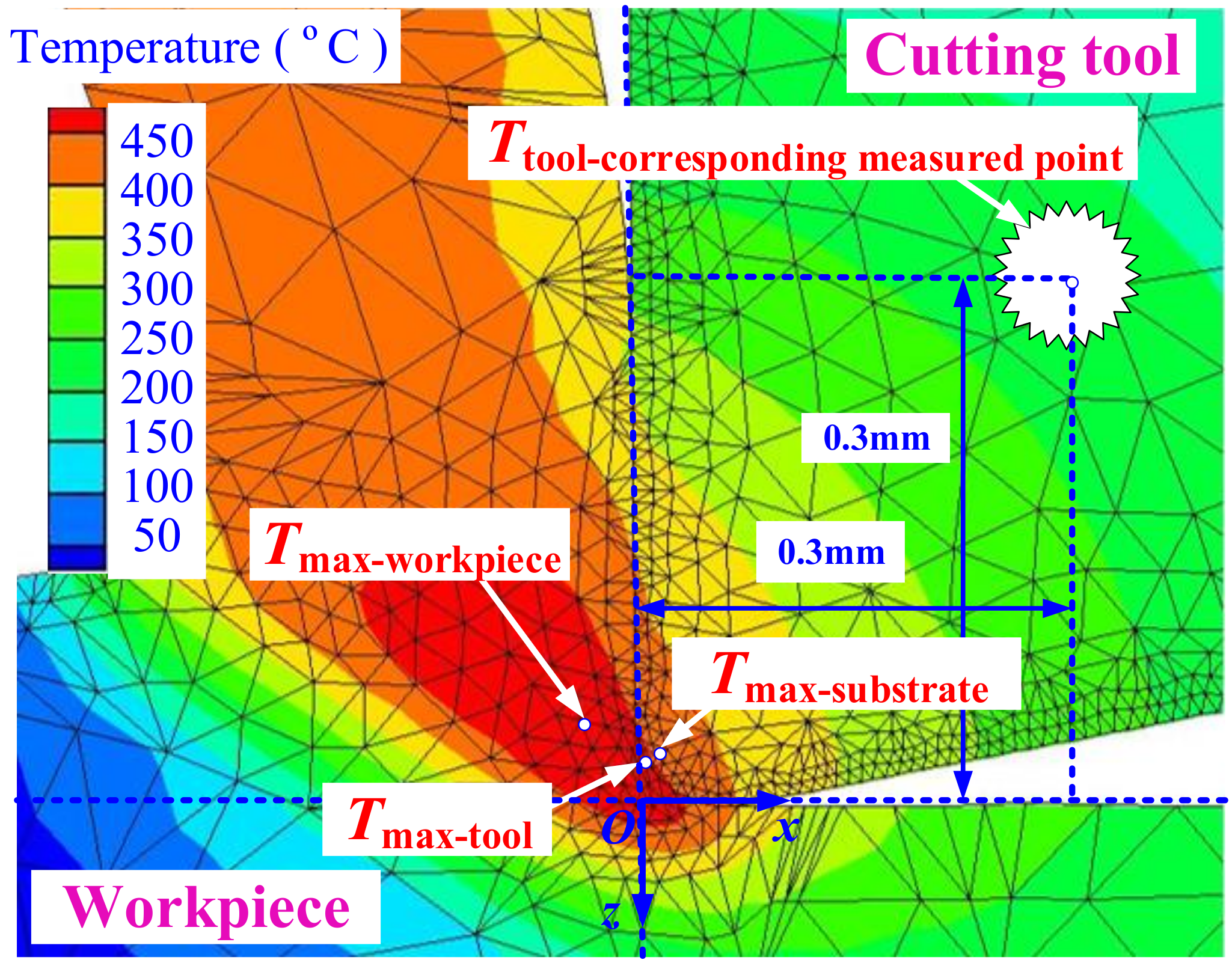
| Tmax-workpiece | Maximum temperature of workpiece during cutting process, °C |
| u | Integral variable of shear band length |
| Tprimary | Temperature generated by the primary shear heat source, °C |
| Timaginary | Temperature generated by the imaginary shear heat source, °C |
| Tmax-tool | Maximum temperature of tool during cutting process, °C |
| Tmax-substrate | Maximum temperature of substrate during cutting process, °C |
| Greek symbols | |
| φ | Shear angle, ° |
| γ0 | Rake angle, ° |
| λ | Thermal conductivity, W/(m·K) |
| ρ | Density, kg/m3 |
| ω | Function of the time variable t |
| β | Relief angle, ° |
References
- Grzesik, W.; Niesłony, P.; Habrat, W.; Sieniawski, J.; Laskowski, P. Investigation of tool wear in the turning of Inconel 718 superalloy in terms of process performance and productivity enhancement. Tribol. Int. 2018, 118, 337–346. [Google Scholar] [CrossRef]
- Polvorosa, R.; Suárez, A.; López de Lacalle, L.N.; Cerrillo, I.; Wretland, A.; Veiga, F. Tool wear on nickel alloys with different coolant pressures: Comparison of Alloy 718 and Waspaloy. J. Manuf. Process. 2017, 26, 44–56. [Google Scholar] [CrossRef]
- Yan, P.; Chen, K.; Wang, Y.B.; Zhou, H.; Peng, Z.Y.; Li, J.; Wang, X.B. Design and Performance of property gradient ternary nitride coating based on process control. Materials 2018, 11, 758. [Google Scholar] [CrossRef] [PubMed]
- Fernández-Valdivielso, A.; López de Lacalle, L.N.; Urbikain, G.; Rodriguez, A. Detecting the key geometrical features and grades of carbide inserts for the turning of nickel-based alloys concerning surface integrity. Proc. Inst. Mech. Eng. Part C J. Mech. Eng. Sci. 2015, 230, 1989–1996. [Google Scholar] [CrossRef]
- Beranoagirre, A.; Olvera, D.; López de Lacalle, L.N. Milling of gamma titanium–aluminum alloys. Int. J. Adv. Manuf. Technol. 2012, 62, 83–88. [Google Scholar] [CrossRef]
- Palanisamy, S.; Rahman Rashid, R.A.; Brandt, M.; Dargusch, M.S. Tool life study of coated/uncoated carbide inserts during turning of Ti6Al4V. Adv. Mater. Res. 2014, 974, 136–140. [Google Scholar] [CrossRef]
- Palanisamy, S.; Rahman Rashid, R.A.; Brandt, M.; Sun, S.; Dargusch, M.S. Comparison of endmill tool coating performance during machining of Ti6Al4V Alloy. Adv. Mater. Res. 2014, 974, 126–131. [Google Scholar] [CrossRef]
- Kupczyk, M.J. Cutting edges with high hardness made of nanocrystalline cemented carbides. Int. J. Refract. Met. Hard Mater. 2014, 974, 126–131. [Google Scholar] [CrossRef]
- Wojciechowski, S.; Twardowski, P.; Wieczorowski, M. Surface texture analysis after ball end milling with various surface inclination of hardened steel. Metrol. Meas. Syst. 2014, 21, 145–156. [Google Scholar] [CrossRef]
- Zaleski, K. A study on the properties of surface–active fluids used in burnishing and shot peening processes. Adv. Sci. Technol. Res. J. 2016, 10, 235–239. [Google Scholar] [CrossRef]
- Rodríguez-Barrero, S.; Fernández-Larrinoa, J.; Azkona, I.; López de Lacalle, L.N.; Polvorosa, R. Enhanced performance of nanostructured coatings for drilling by droplet elimination. Mater. Manuf. Process. 2016, 31, 593–602. [Google Scholar] [CrossRef]
- Feldshtein, E.; Józwik, J.; Legutko, S. The influence of the conditions of emulsion mist formation on the surface roughness of AISI 1045 steel after finish turning. Adv. Sci. Technol. Res. J. 2016, 10, 144–149. [Google Scholar] [CrossRef]
- Paldey, S.; Deevi, S.C. Single layer and multilayer wear resistant coatings of (Ti, Al) N: A review. Mater. Sci. Eng. A. 2003, 342, 58–79. [Google Scholar] [CrossRef]
- Ding, X.Z.; Samani, M.K.; Chen, G. Thermal conductivity of PVD TiAlN films using pulsed photothermal reflectance technique. Appl. Phys. A 2010, 101, 573–577. [Google Scholar] [CrossRef]
- Hultman, L. Thermal stability of nitride thin films. Vacuum 2000, 57, 1–30. [Google Scholar] [CrossRef]
- Wahlström, U.; Hultman, L.; Sundgren, J.E.; Adibi, F.; Petrov, I.; Greene, J.E. Crystal growth and microstructure of polycrystalline Ti1−xAlxN alloy films deposited by ultra-high-vacuum dual-target magnetron sputtering. Thin Solid Films 1993, 235, 62–70. [Google Scholar] [CrossRef]
- Yoon, J.S.; Leea, H.Y.; Hana, J.G.; Yangb, S.H.; Musilc, J. The effect of Al composition on the microstructure and mechanical properties of WC–TiAlN superhard composite coating. Surf. Coat. Technol. 2001, 142, 596–602. [Google Scholar] [CrossRef]
- Barsoum, M.W.; Rawn, C.J.; El-Raghy, T.; Procopio, A.T.; Porter, W.D.; Wang, H.; Hubbard, C.R. Thermal properties of Ti4AlN3. J. Appl. Phys. 2000, 87, 8407–8414. [Google Scholar] [CrossRef]
- Rachbauer, R.; Gengler, J.J.; Voevodin, A.A.; Resch, K.; Mayrhofer, P.H. Temperature driven evolution of thermal, electrical, and optical properties of Ti–Al–N coatings. Acta Mater. 2012, 60, 2091–2096. [Google Scholar] [CrossRef] [PubMed]
- Du, F.; Lovell, M.R.; Wu, T.W. Boundary element method analysis of temperature fields in coated cutting tools. Int. J. Solids. Struct. 2001, 38, 4557–4570. [Google Scholar] [CrossRef]
- Müller, B.; Renz, U. Time resolved temperature measurements in manufacturing. Measurement 2003, 34, 363–370. [Google Scholar] [CrossRef]
- Davoudinejad, A.; Tosello, G.; Parenti, P.; Annoni, M. 3D Finite element simulation of micro end-milling by considering the effect of tool run-out. Micromachines 2017, 8, 187. [Google Scholar] [CrossRef]
- Grzesik, W. The role of coatings in controlling the cutting process when turning with coated indexable inserts. J. Mater. Process. Technol. 1998, 79, 133–143. [Google Scholar] [CrossRef]
- Komanduri, R.; Hou, Z.B. Thermal modeling of the metal cutting process: Part I—Temperature rise distribution due to shear plane heat source. Int. J. Mech. Sci. 2000, 42, 1715–1752. [Google Scholar] [CrossRef]
- Huang, K.; Yang, W.Y. Analytical model of temperature field in workpiece machined surfacelayer in orthogonal cutting. J. Mater. Process. Technol. 2016, 229, 375–389. [Google Scholar] [CrossRef]
- Standard Test Method for Adhesion Strength and Mechanical Failure Modes of Ceramic Coatings by Quantitative Single Point Scratch Testing; ASTM C1624-05; ASTM International: West Conshohocken, PA, USA, 2015.
- Yang, Y.; Zhao, S.; Gong, J. Effect of heat treatment on the microstructure and residual stresses in (Ti,Al)N films. J. Mater. Sci. Technol. 2011, 27, 385–392. [Google Scholar] [CrossRef]
- Saif, M.T.A.; Hui, C.Y.; Zehnder, A.T. Interface shear stresses induced by non-uniform heating of a film on a substrate. Thin Solid Films 1993, 224, 159–167. [Google Scholar] [CrossRef]
- Akbar, F.; Mativenga, P.T.; Sheikh, M.A. On the heat partition properties of (Ti, Al) N compared with TiN coating in high-speed machining. Proc. Inst. Mech. Eng. Part B J. Eng. 2009, 223, 363–375. [Google Scholar] [CrossRef]
- Lamikiz, A.; López De Lacalle, L.N.; Sánchez, J.A.; Salgado, M.A. Cutting force integration at the CAM stage in the high-speed milling of complex surfaces. Int. J. Comput. Integr. Manuf. 2007, 18, 586–600. [Google Scholar] [CrossRef]
- Ucun, İ.; Aslantas, K.; Bedir, F. Finite element modeling of micro-milling: Numerical simulation and experimental validation. Mach. Sci. Technol. 2016, 20, 148–172. [Google Scholar] [CrossRef]
- Savkova, J.; Blahova, O. Scratch resistance of TiAlSiN coatings. Chem. Listy 2011, 105, 214–217. [Google Scholar]
- Hsieh, J.H.; Liang, C.; Yu, C.H.; Wu, W. Deposition and characterization of TiAlN and multi-layered TiN/TiAlN coatings using unbalanced magnetron sputtering. Surf. Coat. Technol. 1998, 108, 132–137. [Google Scholar] [CrossRef]
- Finkel, P.; Barsoum, M.W.; El-Raghy, T. Low temperature dependencies of the elastic properties of Ti4AlN3, Ti3Al1.1C1.8, and Ti3SiC2. J. Appl. Phys. 2000, 87, 1701–1703. [Google Scholar] [CrossRef]
- Gu, L.Y.; Kang, G.Z.; Chen, H.; Wang, M.J. On adiabatic shear fracture in high-speed machining of martensitic precipitation-hardening stainless steel. J. Mater. Process. Technol. 2016, 234, 208–216. [Google Scholar] [CrossRef]
- Grezsik, W.P. Experimental investigation of the cutting temperature when turning with coated indexable inserts. Int. J. Mach. Tools Manuf. 1999, 39, 355–369. [Google Scholar] [CrossRef]
- Devillez, A.; Schneider, F.; Dominiak, S.; Dudzinski, D.; Larrouquere, D. Cutting forces and wear in dry machining of Inconel 718 with coated carbide tools. Wear 2007, 262, 931–942. [Google Scholar] [CrossRef]


| x | HV0.025 (GPa) | Critical Loads (N) | Roughness Ra (μm) | Friction Coefficient (Dry) |
|---|---|---|---|---|
| 0.45 | 13.18 | 31.67 ± 2.37 | 0.561 ± 0.003 | 0.35 |
| 0.59 | 15.05 | 38.27 ± 0.67 | 0.516 ± 0.023 | 0.33 |
| Values at the Following Various Temperatures | |||||
|---|---|---|---|---|---|
| 100 °C | 300 °C | 500 °C | 700 °C | 900 °C | |
| Properties of Ti0.41Al0.59N coating [14,27,33] | |||||
| Young’s modulus, GPa | 370 (assumed as unchanged with temperature) | ||||
| Poisson’s ratio | 0.22 (assumed as unchanged with temperature) | ||||
| Density, kg/m3 | 1892 (assumed as unchanged with temperature) | ||||
| Thermal conductivity, W/(m·K) | 12.61 | 14.01 | 15.41 | 16.81 | 18.21 |
| Specific heat, J/(kg·K) | 639.89 | 727.28 | 769.46 | 794.29 | 810.67 |
| Properties of Ti0.55Al0.45N coating [14,27,33] | |||||
| Young’s modulus, GPa | 370 (assumed as unchanged with temperature) | ||||
| Poisson’s ratio | 0.22 (assumed as unchanged with temperature) | ||||
| Density, kg/m3 | 1892 (assumed as unchanged with temperature) | ||||
| Thermal conductivity, W/(m·K) | 10.61 | 12.01 | 13.41 | 14.81 | 16.21 |
| Specific heat, J/(kg·K) | 639.89 | 727.28 | 769.46 | 794.29 | 810.67 |
| Properties of tungsten-based cemented carbide [27] | |||||
| Young’s modulus, GPa | 534 (assumed as unchanged with temperature) | ||||
| Poisson’s ratio | 0.22 (assumed as unchanged with temperature) | ||||
| Density, kg/m3 | 11900 (assumed as unchanged with temperature) | ||||
| Thermal conductivity, W/(m·K) | 40.15 | 48.55 | 56.95 | 65.35 | 73.75 |
| Specific heat, J/(kg·K) | 346.01 | 370.01 | 394.01 | 418.01 | 442.01 |
| Type | f (mm/rev) | φ (°) | L (mm) | B | qshear (J/(mm2·s)) |
|---|---|---|---|---|---|
| KC5010 | 0.025 | 28.11 ± 0.22 | 0.0843 ± 0.0105 | 1.129 | 67.2738 ± 0.0351 |
| 0.050 | 31.04 ± 0.15 | 0.1522 ± 0.0078 | 0.873 | 63.3973 ± 0.0530 | |
| 0.075 | 32.23 ± 0.11 | 0.2203 ± 0.0156 | 0.751 | 50.6745 ± 0.0236 | |
| KC5025 | 0.025 | 26.21 ± 0.19 | 0.0838 ± 0.0245 | 1.129 | 70.0889 ± 0.2371 |
| 0.050 | 29.13 ± 0.15 | 0.1538 ± 0.0218 | 0.873 | 65.4005 ± 0.1052 | |
| 0.075 | 30.52 ± 0.24 | 0.1891 ± 0.0027 | 0.751 | 54.8375 ± 0.0032 | |
| K313 | 0.025 | 27.84 ± 0.11 | 0.0831 ± 0.0178 | 1.129 | 66.6349 ± 0.0261 |
| 0.050 | 29.53 ± 0.21 | 0.1564 ± 0.0205 | 0.873 | 63.4259 ± 0.0331 | |
| 0.075 | 29.21 ± 0.15 | 0.2143 ± 0.0137 | 0.751 | 60.5648 ± 0.0082 |
© 2018 by the authors. Licensee MDPI, Basel, Switzerland. This article is an open access article distributed under the terms and conditions of the Creative Commons Attribution (CC BY) license (http://creativecommons.org/licenses/by/4.0/).
Share and Cite
Zhao, J.; Liu, Z.; Shen, Q.; Wang, B.; Wang, Q. Investigation of Cutting Temperature during Turning Inconel 718 with (Ti,Al)N PVD Coated Cemented Carbide Tools. Materials 2018, 11, 1281. https://doi.org/10.3390/ma11081281
Zhao J, Liu Z, Shen Q, Wang B, Wang Q. Investigation of Cutting Temperature during Turning Inconel 718 with (Ti,Al)N PVD Coated Cemented Carbide Tools. Materials. 2018; 11(8):1281. https://doi.org/10.3390/ma11081281
Chicago/Turabian StyleZhao, Jinfu, Zhanqiang Liu, Qi Shen, Bing Wang, and Qingqing Wang. 2018. "Investigation of Cutting Temperature during Turning Inconel 718 with (Ti,Al)N PVD Coated Cemented Carbide Tools" Materials 11, no. 8: 1281. https://doi.org/10.3390/ma11081281
APA StyleZhao, J., Liu, Z., Shen, Q., Wang, B., & Wang, Q. (2018). Investigation of Cutting Temperature during Turning Inconel 718 with (Ti,Al)N PVD Coated Cemented Carbide Tools. Materials, 11(8), 1281. https://doi.org/10.3390/ma11081281