The Application of Globular Water-Atomized Iron Powders for Additive Manufacturing by a LENS Technique

 , ,
, , 
 ,
,  and
and
Abstract
:1. Introduction
2. Materials and Methods
3. Results and Discussion
3.1. Powder Characterization
3.2. The Role of Vibration in the Powder Feed System
3.3. Characterization of Fabricated Samples
4. Conclusions
- 1.
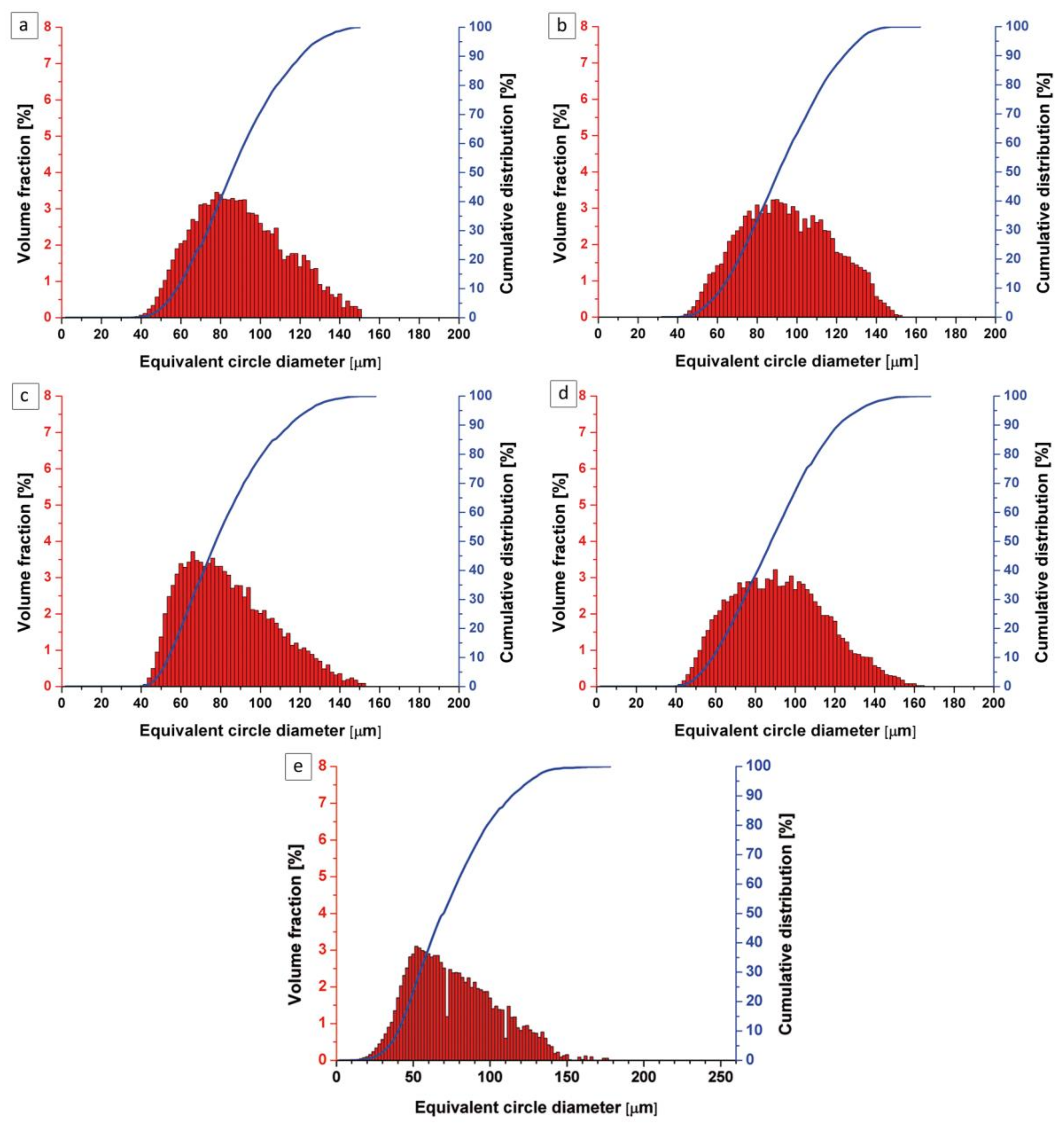
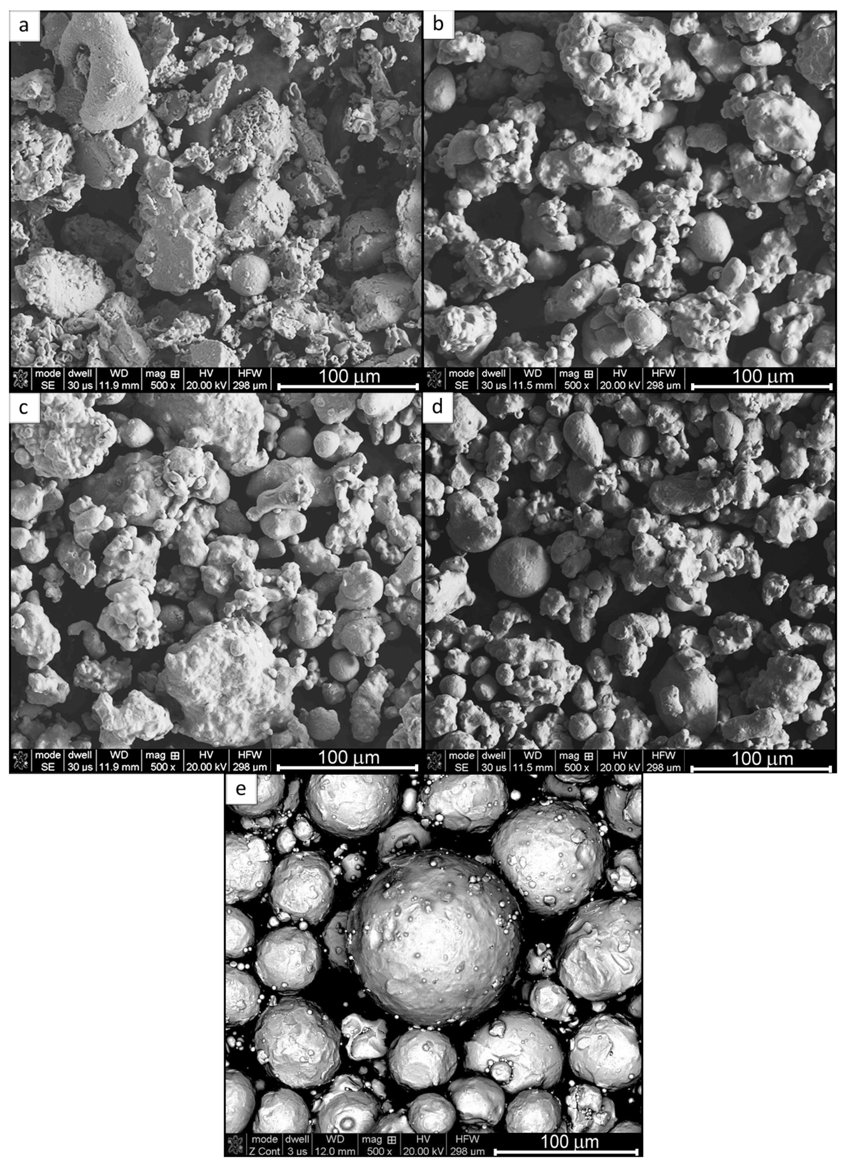
- The four, water-atomized, nonspherical ATOMET powders—designated as ATOMET 28, 1001, 4701, and 4801—were characterized by an overall rounded, globular morphology and relatively wide particle size distribution from 20 to 200 µm.
- 2.
- As an exception, the ATOMET 28 powder was characterized by a strong inhomogeneity of particle size and irregular polyhedral shape of powder particles with sharp edges.
- 3.
- Before the LENS processing of solid samples, all four ATOMET powders were pre-sieved to the size range 40–150 µm.
- 4.
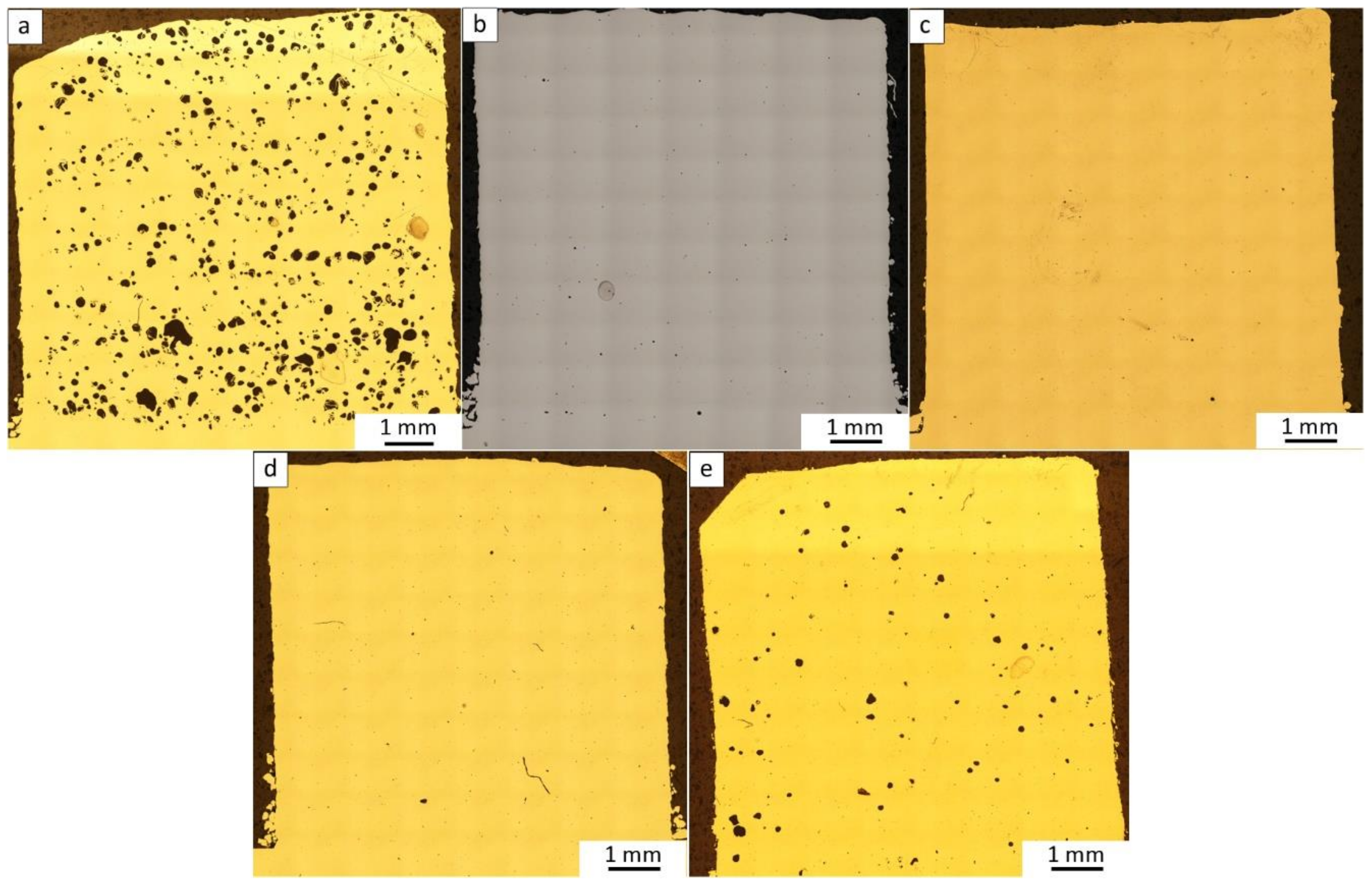
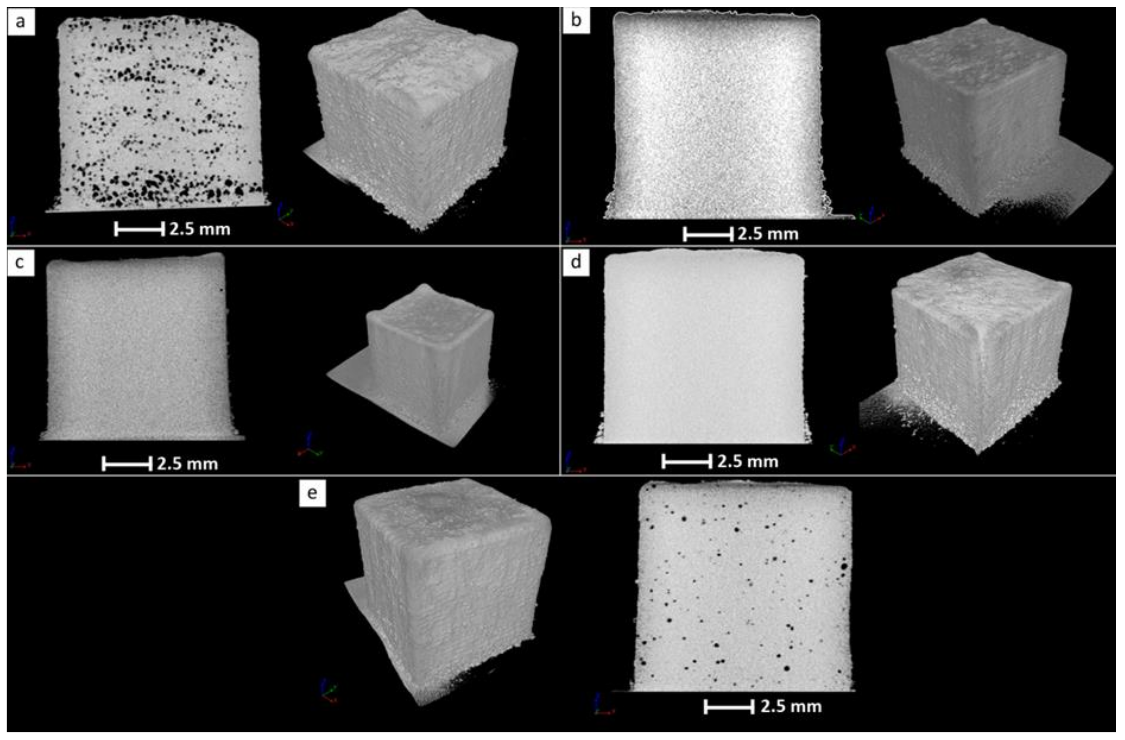
- The nearly cubic solid sample from the LENS-fabricated ATOMET 28 powder exhibited the largest cross-sectional (2D) porosity of 4.2% and bulk porosity of 3.9%, the latter obtained from the microtomography measurements. This is most likely due to the strong inhomogeneity of particle size and irregular polyhedral shape of powder particles with sharp edges present in this particular powder. In contrast, the cross-sectional porosities of bulk, solid, nearly cubic samples from the other LENS-fabricated ATOMET powders exhibited very low porosities within the range 0.03–0.1%.
- 5.
- Surprisingly, the solid sample from the LENS-fabricated reference, purely spherical Fe 99.8 powder, exhibited the second largest porosity of 1.1%, after that of the pre-sieved, nonspherical ATOMET 28 powder.
- 6.
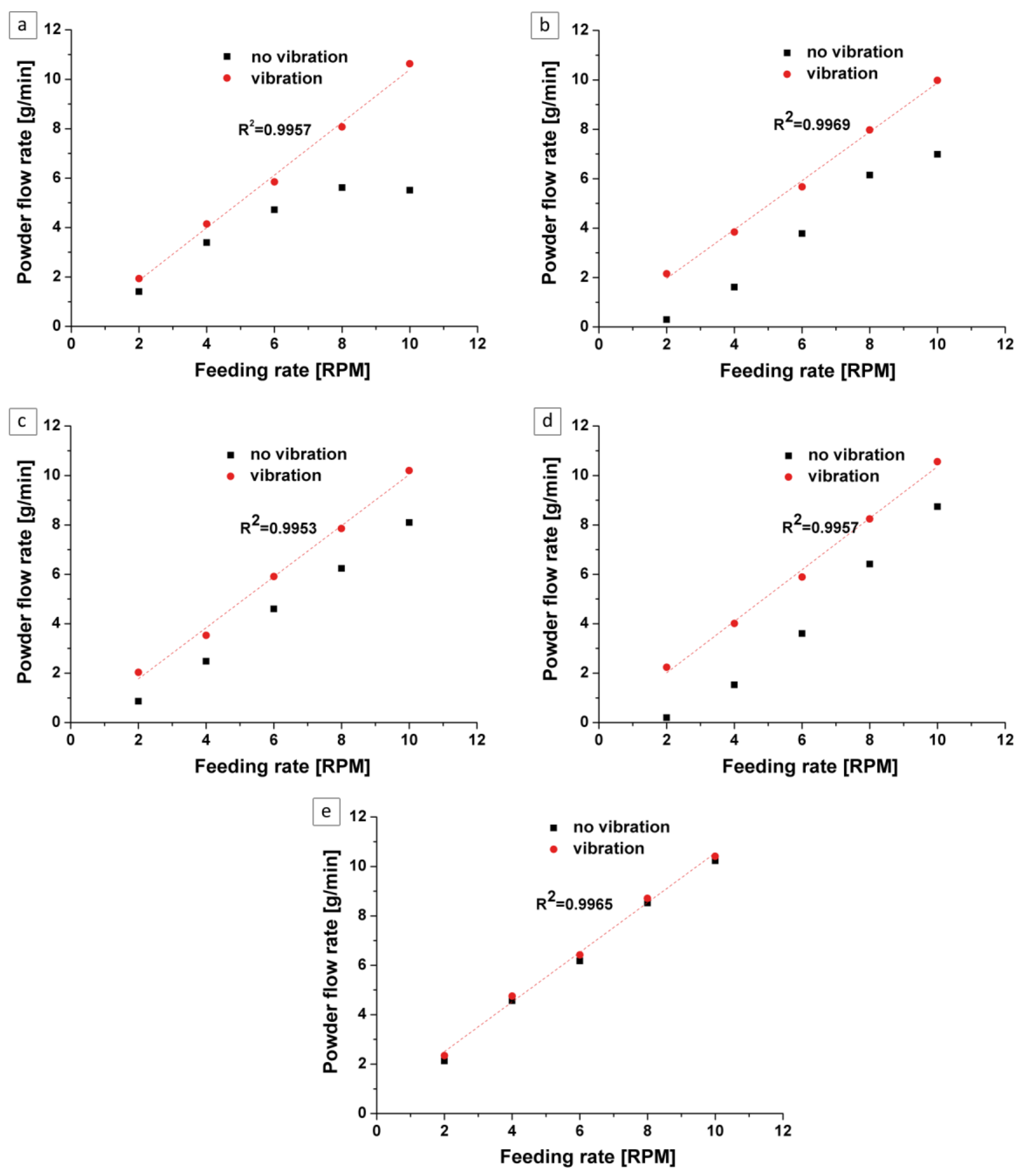
- Incorporation of vibrations into the LENS powder feeding system substantially improved the flow rate vs. feeding rate dependence, making it completely linear with excellent coefficients of fit R2 = 0.99.
- 7.
- Interestingly, the reference powder Fe 99.8 always exhibited a linear dependence between the flow rate vs. feeding rate regardless of whether or not vibrations were incorporated into the powder feeding system. Apparently, a purely spherical powder eliminates any LENS feeding problems.
Author Contributions
Funding
Acknowledgments
Conflicts of Interest
References
- Fayazfar, H.; Salarian, M.; Rogalsky, A.; Sarker, D.; Russo, P.; Paserin, V.; Toyserkani, E. A critical review of powder-based additive manufacturing of ferrous alloys: Process parameters, microstructure and mechanical properties. Mater. Des. 2018, 144, 98–128. [Google Scholar] [CrossRef]
- Letenneur, M.; Brailovski, V.; Kreitcberg, A.; Paserin, V.; Bailon-Poujol, I. Laser Powder Bed Fusion of Water-Atomized Iron-Based Powders: Process Optimization. J. Manuf. Mater. Process. 2017, 1, 23. [Google Scholar] [CrossRef]
- Inaekyan, K.; Paserin, V.; Bailon-Poujol, I.; Brailovski, V. Binder-jetting additive manufacturing with water atomized iron powders. In Proceedings of the AMPM 2016 Conference on Additive Manufacturing, Boston, MA, USA, 5–7 June 2016. [Google Scholar]
- Marucci, M.L.; Catanese, J.A. Production of Powder Metallurgy Carbon and Low-Alloy Steels; ASM Handbook, Volume 7: Powder Metallurgy; ASM International: Almere, The Netherlands, 2015; pp. 311–321. [Google Scholar]
- Palousek, D.; Pantelejev, L.; Zikmund, T.; Koutny, D. Processing of the Nearly Pure Iron Using 400 w Selective Laser Melting–Initial Study. Mod. Mach. Sci. J. 2017, 1738–1743. [Google Scholar] [CrossRef]
- OPTOMEC–LENS. MR-7 PSU System Manual; Made in the USA; OPTOMEC: Albuquerque, NM, USA, 2009. [Google Scholar]
- Durejko, T.; Ziętala, M.; Polkowski, W.; Czujko, T. Thin wall tubes with Fe3Al/SS316L graded structure obtained by using laser engineered net shaping technology. Mater. Des. 2014, 63, 766–774. [Google Scholar] [CrossRef]
- OPTOMEC. 2018. Available online: http://www.optomec.com/3d-printed-metals/lens-materials/ (accessed on 17 May 2018).
- Montani, M.; Demir, A.G.; Mostaed, E.; Vedani, M.; Previtali, B. Processability of pure Zn and pure Fe by SLM for biodegradable metallic implant manufacturing. Rapid Prototyp. J. 2017, 23, 514–523. [Google Scholar] [CrossRef]


| ATOMET Powder | Element (wt %) | |||||||
|---|---|---|---|---|---|---|---|---|
| Fe | C | O | S | Mn | Mo | Ni | Cr | |
| 28 | Bal. | 0.042 | 0.110 | 0.011 | na | na | na | na |
| 1001 | Bal. | 0.004 | 0.070 | 0.011 | 0.169 | na | na | na |
| 4701 | Bal. | 0.014 | 0.170 | 0.009 | 0.447 | 1.011 | 0.897 | 0.471 |
| 4801 | Bal. | 0.005 | 0.070 | 0.006 | 0.137 | 0.537 | 3.945 | na |
| Fe 99.8 | Bal. | 0.050 | 0.120 | n/a | n/a | n/a | n/a | n/a |
| ATOMET 28 | ATOMET 1001 | ATOMET 4701 | ATOMET 4801 | Fe 99.8 | ||
|---|---|---|---|---|---|---|
| Number of coils | 3 | 3 | 3 | 3 | 3 | |
| Gas (L/min) | Laser | 40 | 40 | 40 | 40 | 40 |
| Powder | 2.8 | 2.8 | 2.8 | 2.8 | 2.8 | |
| Power (W) | 300 | 300 | 300 | 300 | 300 | |
| Feeding rate (RPM) | 6 | 6 | 6 | 6.2 | 4.6 | |
| Travel (mm/s) | Contour | 10.5 | 9.5 | 9.5 | 9.5 | 11.5 |
| Filling | 15 | 15 | 15 | 15 | 15 | |
| Set up movement | 10 | 10 | 10 | 10 | 10 | |
| Layer thickness (mm) | 0.2 | 0.2 | 0.2 | 0.2 | 0.2 | |
| Hatch | deg | 0°/90° | 0°/90° | 0°/90° | 0°/90° | 0°/90° |
| (mm) | 0.3 | 0.35 | 0.3 | 0.3 | 0.3 | |
| Hatch shrink | 0.05 | 0.05 | 0.05 | 0.05 | 0.05 | |
| Vibration | 1 bar, 45° | 1 bar, 45° | 1 bar, 45° | 1 bar, 45° | 1 bar, 45° | |
| Remarks | Acc/dec: 40,000 | Acc/dec: 40,000 | Acc/dec: 40,000 | Acc/dec: 40,000 | Acc/dec: 40,000 | |
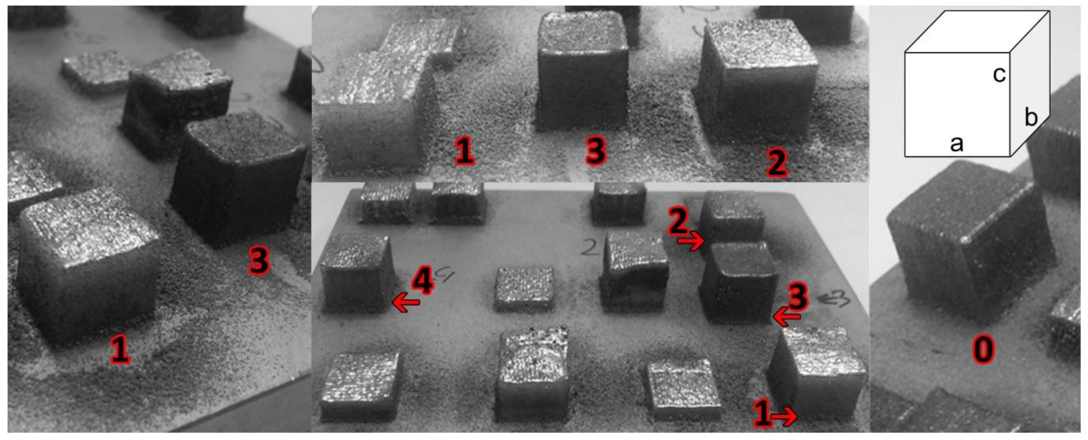
| ATOMET Powder | a (mm) | b (mm) | c (mm) |
|---|---|---|---|
| 28 | 10.51 | 10.55 | 10.52 |
| 1001 | 10.47 | 10.40 | 10.42 |
| 4701 | 10.45 | 10.40 | 10.47 |
| 4801 | 10.49 | 10.41 | 10.50 |
| Fe 99.8 | 10.53 | 10.50 | 10.47 |
| ATOMET Powder | Lateral Surface | Top Surface | ||
|---|---|---|---|---|
| Ra (µm) | Wa (µm) | Ra (µm) | Wa (µm) | |
| 28 | 10.0 ± 0.9 | 3.7 ± 0.5 | 13.1 ± 1.4 | 2.3 ± 0.6 |
| 1001 | 13.7 ± 1.1 | 5.8 ± 0.6 | 22.9 ± 1.1 | 21.3 ± 1.5 |
| 4701 | 12.1 ± 1.3 | 2.9 ± 0.4 | 25.3 ± 1.4 | 13.7 ± 1.1 |
| 4801 | 5.4 ± 0.8 | 1.0 ± 0.1 | 10.5 ± 1.8 | 10.0 ± 1.5 |
| Fe 99.8 | 11.4 ± 1.2 | 4.0 ± 0.4 | 20.1 ± 1.2 | 4.9 ± 0.7 |
| ATOMET and Reference Powder | Porosity LENS-Fabricated Sample (%) |
|---|---|
| 28 | 4.2 |
| 1001 | 0.1 |
| 4701 | 0.03 |
| 4801 | 0.1 |
| Fe 99.8 | 1.1 |
© 2018 by the authors. Licensee MDPI, Basel, Switzerland. This article is an open access article distributed under the terms and conditions of the Creative Commons Attribution (CC BY) license (http://creativecommons.org/licenses/by/4.0/).
Share and Cite
Durejko, T.; Aniszewska, J.; Ziętala, M.; Antolak-Dudka, A.; Czujko, T.; Varin, R.A.; Paserin, V. The Application of Globular Water-Atomized Iron Powders for Additive Manufacturing by a LENS Technique. Materials 2018, 11, 843. https://doi.org/10.3390/ma11050843
Durejko T, Aniszewska J, Ziętala M, Antolak-Dudka A, Czujko T, Varin RA, Paserin V. The Application of Globular Water-Atomized Iron Powders for Additive Manufacturing by a LENS Technique. Materials. 2018; 11(5):843. https://doi.org/10.3390/ma11050843
Chicago/Turabian StyleDurejko, Tomasz, Justyna Aniszewska, Michał Ziętala, Anna Antolak-Dudka, Tomasz Czujko, Robert A. Varin, and Vlad Paserin. 2018. "The Application of Globular Water-Atomized Iron Powders for Additive Manufacturing by a LENS Technique" Materials 11, no. 5: 843. https://doi.org/10.3390/ma11050843
APA StyleDurejko, T., Aniszewska, J., Ziętala, M., Antolak-Dudka, A., Czujko, T., Varin, R. A., & Paserin, V. (2018). The Application of Globular Water-Atomized Iron Powders for Additive Manufacturing by a LENS Technique. Materials, 11(5), 843. https://doi.org/10.3390/ma11050843