Abstract
In this paper, a modified Fourier series method is presented for the free vibration of moderately thick orthotropic functionally graded plates with general boundary restraints based on the first-order shear deformation theory. Regardless of boundary restraints, displacements and rotations of each plate are described as an improved form of double Fourier cosine series and several closed-form auxiliary functions to eliminate all the boundary discontinuities and jumps. Exact solutions are obtained by the energy functions of the plates based on Rayleigh-Ritz method. The convergence and reliability of the current method and the corresponding theoretical formulations are verified by comparing the present results with those available in the literature, and numerous new results for orthotropic functionally graded (OFG) plates with general boundary restraints are presented. In addition, the effects of gradient index, volume fraction and geometric parameters on frequencies with general boundary restraints are illustrated.
1. Introduction
As a kind of novel composite materials, functionally graded materials (FGMs) can be characterized by the variation in composition and structure gradually over volume, resulting in continuous changes along the desired directions. Compared to laminated plates, the continuity of FGMs properties eliminates interfacial stresses at the junctions of materials [1,2,3,4]. Therefore, FG plates have been widely used in various engineering fields, such as aircraft, nuclear and automobile manufacturing [5,6,7,8,9]. As we all known, dynamic load is unavoidable on the practical applications, and it may lead to fatigue damage and stability reduction of the structures. Thus, it is necessary to study the vibration characteristics of FG plate structures.
To deal with the vibration problem of FG plates, many accurate and efficient calculation methods have been developed in the last few decades, such as extended Kantorovich method [10], Ritz method [11,12,13], power series method [14], meshless method [15,16,17], wave propagation approach [18], finite element method [19,20], etc. Chi et al. [21,22] studied the bending problem of FG rectangular plates based on the classical plate theory. Qian et al. [23] applied high-order shear and normal deformable plate theory to study the static and dynamic deformations of FG plates. Liu et al. [24] used an element-free Galerkin method to study the dynamic response of FG plate containing distributed piezoelectric actuators and sensors. It should be emphasized that most of these methods were applied to isotropic structures which are only considering the change of the Young’s modulus in the thickness. However, due to the limitations of the process conditions, most of the FGMs are orthotropic. The vibration analysis of the orthotropic functionally graded (OFG) plates has been the goal of intensive research, and many studies have been devoted to the OFG plates in the literature. Ramirez et al. [25] used the discrete layer theory in combination with the Ritz method to obtain an approximate solution for static analysis of OFG plates. Zhang et al. [26] adapted the third-order shear deformation theory to analyze chaotic vibrations of an OFG plate. Huang et al. [27] developed a discrete method for solving the vibration problem of orthotropic rectangular plates with variable thickness in one or two directions. Although these methods give sufficiently accurate results for thin plates, they are not valid for the vibration analysis of the moderately thick plates.
To eliminate the deficiency of the aforementioned methods, a Fourier series method was presented by Li [28,29]. This method has been subsequently transferred to the vibration analysis of more structures with various restraints [30,31,32,33,34,35,36,37]. From the review of the literature, most of the previous studies on the OFG plates are defined in a single volume distribution type. However, there are a variety of possible volume distributions in practical engineering applications, and these distributions have great influence on the vibration properties of the OFG plates. According to the effects of gradient index on the volume fraction in different distributions, the material properties change continuously through the thickness of the OFG plates.
Therefore, the objective of the present work is to provide an accurate and reliable method for the free vibration analysis of moderately thick OFG plates in various volume distribution types with general restraints. Displacements and rotations of each plate, regardless of boundary restraints, are described as an improved form of double Fourier cosine series and several closed-form auxiliary functions. Exact solutions are obtained by the energy functions of the plates based on Rayleigh–Ritz method. The excellent accuracy and reliability of the current results are verified by comparing the present solutions with those available in the literature. Studies focused on free vibration properties of OFG plates are presented, which may serve as a supplement of the material performance of OFG plates.
2. Theoretical Formulation
2.1. Model Description
A moderately thick OFG plate with length a, width b, and uniform thickness h is depicted in Figure 1. The reference surface is taken to be its middle surface where the plate geometry and dimensions are arranged in a Cartesian coordinate system (x, y, z). The displacements of the plate in the x, y, and z directions are denoted by u, v and w, respectively. The general boundary conditions are assumed to be restrained by three independent springs (translational, rotational and torsional springs) placed at the ends. Assigning the stiffness of the springs with various values from zero to infinity is equivalent to imposing different boundary forces on the plate. For example, a free boundary is obtained by setting the stiffness of springs to zero, and a clamped boundary is obtained by setting the stiffness of springs to infinity. For moderately thick plates, the Kirchhoff hypothesis is relaxed by assuming that the normal to the undeformed middle surface is not perpendicular to the deformed middle surface.
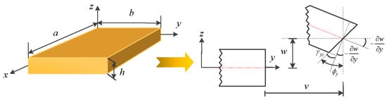
Figure 1.
Schematic diagram of a moderately thick OFG plate with the undeformed and deformed geometries of an edge including shear deformation.
2.2. Material Properties
Typically, OFG plates are made from a mixture of two materials in different proportions, for example, the metal and ceramic used in the following analyses are listed in Table 1. Material parameters per unit volume are assumed to vary continuously through the plate thickness and can be obtained:
where E1 and E2 represent the horizontal and vertical Young’s modulus, respectively; and ρ are the major Poisson ratio and density, respectively; and are the Young’s modulus of ceramic and metal, respectively; and are ceramic’s Poisson ratio and density, respectively; and are metal’s Poisson ratio and density, respectively; and and denote the volume fractions of ceramic and metal, respectively. The shear modulus of the material can be given by:
where and are the shear modulus of ceramic and metal. G12 is composite structure’s shear modulus. Furthermore, according to different ceramic-to-metal volume distributions in the thickness direction, the OFG plates are assumed as three types, P-, C- and S-OFG, respectively. in the thickness direction z can be expressed as:
where and are available minimum and maximum values of . Especially for P- and C-OFG, and represent the ceramic volume fractions of bottom and top surfaces, respectively. In addition, p is the gradient index and only takes non-negative values. When the value of p varies between zero and infinity, non-homogeneous material properties can be obtained.

Table 1.
Main material properties of the used OFG plates.
2.3. Stress–Strain Relations and Stress Resultants
Based on the assumptions of the first-order shear deformation theory (FSDT) [38,39], the displacement components of moderately thick OFG plates are:
where u, v and w denote the middle surface displacements of the plate in the x, y and z directions, respectively. ϕx and ϕy represent the transverse normal rotations of the reference surface respect to the y and x directions. Under the assumption of linear and small deformation, the strains and curvature can be defined in terms of displacements as:
where , and are the normal and shear strains in the x, y and z directions. and indicate the transverse shear strains, which are assumed to be constants through the thickness. The matrix can be denoted as:
According to the generalized Hooke’s law [40], the corresponding stress–strain relations of a moderately thick OFG plate can be expressed as follows:
where the elastic constants are defined in terms of the material properties as:
The force and moment resultants are obtained by integrating the stresses over the plate thickness:
where , and are the force resultants. , and are the moment resultants. The transverse shear force resultants are denoted as and , respectively. Performing the integration operation in Equations (10)–(12), the force and moment resultants can be written as:
The stiffness coefficients , and are expressed as:
2.4. Energy Functions
In this subsection, the modified Fourier series version of Rayleigh–Ritz method is presented. In the Rayleigh–Ritz method, a displacement field associated with undetermined coefficients is assumed firstly, and substituted into the Lagrangian energy function [41]. Then, the undetermined coefficients in the displacement field can be obtained by finding the stationary value of the energy function, namely, minimizing the energy function with respect to the undetermined coefficients and making them equal to zero. Finally, a series of equations related to corresponding coefficients can be achieved and summed up in matrix form as a standard characteristic equation. The desired frequencies of the structure can be determined easily by solving the standard characteristic equation.
For free vibration analysis, the Lagrangian energy function of the plates can be simplified and written in terms of the strain energy and kinetic energy functions as:
The strain energy Us of the moderately thick OFG plates during vibration can be defined in terms of the middle surface strains, curvature changes and stress resultants as:
Substituting Equations (5), (6), and (13)–(15) into Equation (18), the strain energy can be expressed in terms of displacements (u, v, w) and rotations components (ϕx, ϕy) as:
The kinetic energy T of the vibrating OFG plate is given by:
Assuming the distributed external forces , and are in the x, y and z directions, respectively. mx and my are the external couples in the middle surface. Thus, the work We done by the forces and moments is:
, , , and () are used to indicate the rigidities (per unit length) of the boundary springs at the x = 0, x = a, y = 0 and y = b, respectively (see Figure 2). Therefore, the deformation strain energy (Usp) stored in the boundary springs can be expressed as:
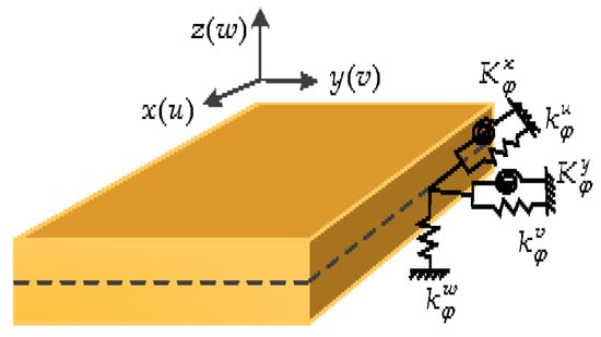
Figure 2.
Boundary restraints of a moderately thick OFG plate.
2.5. Governing Equations and Boundary Restraints
By applying Hamilton’s principle, the governing equations of moderately thick OFG plates can be obtained:
The general boundary restraints for moderately thick OFG plates can be expressed as the following forms:
On x = 0
On x = a
On y = 0
On y = b
2.6. Admissible Displacement Functions
In this subsection, we consider free vibration of moderately thick OFG plates with general boundary restraints. Although the Fourier functions exhibit an excellent numerical stability, conventional Fourier series expression will have a convergence problem along the boundary edges except for a few simple boundary restraints.
This article proposes a modified Fourier series method for the displacement and rotation components of the OFG plates, by an improved form of double Fourier cosine series and several closed-form auxiliary functions. Regardless of boundary conditions, each displacement and rotation component of the OFG plate is expanded as a modified Fourier series as:
where and . M and N denote the truncation numbers with respect to variables x and y, respectively. Amn, Bmn, Cmn, Dmn and Emn are the Fourier expansion coefficients of the cosine Fourier series. , , , , , , , , and are the corresponding supplement coefficients. and denote the auxiliary polynomial functions introduced to remove all the discontinuities potentially associated with the first-order derivatives at the boundaries. The auxiliary functions are expressed as follows:
It is easy to verify that,
All the expansion coefficients in Equation (25) can be treated independently and equally as the generalized coordinates and solved directly from the Ritz method. The method can be summed up in a matrix form as:
where K and M is the stiffness matrix and mass matrix of the OFG plate, respectively. Both are symmetric matrices and can be written as:
The coefficient eigenvector G is the unknown expansion coefficient in the series expansions, and determined for a given frequency, namely:
The Fourier coefficient eigenvector G, stiffness matrix K and mass matrix M are given in the Appendix A.
3. Numerical Results and Discussion
In this section, numerical examples for the free vibration analysis of moderately thick OPG plates with various gradient indexes and general boundary restraints are presented. Firstly, the convergence and reliability of the proposed modified Fourier series method is validated by comparing the current solutions with those results published in the literature under the distribution of P-OFG. Secondly, the free vibration behavior of OFG plates with general boundary restraints is studied. Then, the effects of gradient index p on the volume fraction in the thickness direction, in various distributions (P-, C- and S-OFG), are discussed. Finally, the relations between fundamental frequencies f (Hz) and gradient index p in the various volume fractions with general boundary restraints are contrasted and analyzed as well.
3.1. OFG Plates with General Boundary Restraints
The aforementioned general boundary restraints can be readily realized by assigning the stiffness of the boundary springs at proper values. Taking edge x = 0 as an example, the frequently encountered boundary restraints F (free edge), C (clamped edge) and S (simply-supported edge) can be defined as follows:
where is the flexural stiffness of the plate. The accuracy and convergence of the present solution is demonstrated in Table 2 and Table 3. Table 2 compares the first five frequency parameters of OFG plates with CCCC, SSSS and FFFF boundary restraints and thickness–length ratio a/b = 0.5. Three different thickness–length ratios, h/a = 0.1, 0.2 and 0.3, corresponding to the moderately thick plates, are considered in the comparison. The solution given by Jin et al. [35] by the three-dimensional elasticity method is provided for a direct comparison. The difference does not exceed 0.044% for the worst case, which is acceptable.
Table 2.
The first five frequency parameters of OFG plate with different restraints and thickness–length ratios (a/b = 0.5).
Table 3.
The comparison of non-dimensional frequency parameters for square plates with CCCC, SSSS, CFCF and SCSC boundary restraints, respectively (h/a = 0.2).
The non-dimensional frequency parameters for square plates with CCCC, SSSS, CFCF, and SCSC boundary restraints are shown in Table 3. The thickness–length ratio used for the analysis is h/a = 0.2, and the truncation number is M = N = 9 and 11. It can be seen that the present solutions are in close agreement with the results obtained from TSDT method [15]. In general, a consistent agreement of the present results is seen from the tables by comparing with those available in the literature.
Numerous new results of fundamental frequencies f (Hz) are presented in Table 4 and Table 5 for moderately thick OFG plates with a variety of general boundary restraints. In the case of Table 4 and Table 5, the gradient indexes and geometrical parameters of the OFG plates are taken to be p = 0.5, 2, and 10, and a/b = 1.5 and 2, h/a = 0.2, 0.3, and 0.5. The boundary restraints, including SSSS, SSSC, SSSF, CFCC, CFCS, CFCF, CFSS and CFSF, are considered. It can be seen from the tables that the solutions of the fundamental frequencies f (Hz) corresponding to different boundary restraints have obvious difference. The frequencies of the moderately thick OFG plates with SSSS, SSSC and SSSF are significantly lower the other restraints, this is due to that the smaller restraints at the edges decrease the flexural rigidity of the plate, resulting in smaller frequency response. The frequencies of the OFG plates decrease as thickness–length ratio (h/a) and length–width ratio (a/b) increase. The first four mode shapes with SSSS, SSSC, SSSF, CFCC, CFCS and CFCF boundary restraints are depicted in Figure 3 to further enrich the vibration results of OFG plates. The gradient index and geometrical parameters are set as p = 1, a/b = 1.5, and h/a = 0.3. Next, the effects of gradient index and volume fraction on frequencies in various volume distributions with general boundary restraints are illustrated.
Table 4.
The first four frequencies f (Hz) of moderately thick OFG plates with various boundary restraints, gradient indexes and thickness–length ratios (a/b = 1.5).
Table 5.
The first four frequencies f (Hz) of moderately thick OFG plates with various boundary restraints, gradient indexes and thickness–length ratios (a/b = 2).
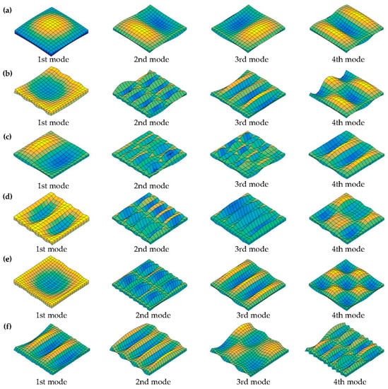
Figure 3.
The first four mode shapes of the moderately thick OFG plates with various boundary restraints: (a) SSSS; (b) SSSF; (c) SSSC; (d) CFCC; (e) CFCS; and (f) CFCF.
3.2. Volume Fraction Analysis
In this study, the material properties are assumed as three types (P-OFG, C-OFG, and S-OFG), which are realized by different ceramic-to-metal volume distributions in the thickness direction. The material properties are assumed to vary through the thickness of the plate with ceramic-to-metal volume distribution between the two surfaces. Specifically, the horizontal and vertical Young’s modulus (E1 and E2), density ρ and main Poisson ratio are assumed to vary continuously through the plate thickness.
According to Equations (1)–(3), the variation of the ceramic volume fraction through coordinate-thickness ratio in various types is presented in Figure 4 (V1 = 0, V2 = 1). In Figure 4a, the volume fraction of ceramic varies quickly near the lowest surface for p < 1 and increases quickly near the top surface for p > 1 under the case of P-OFG. In Figure 4b, the distribution of the ceramic volume fraction is symmetric about the middle surface for C-OFG. In Figure 4c, the distribution is inverse symmetric about the middle surface for S-OFG, and each part is similar to P-OFG.
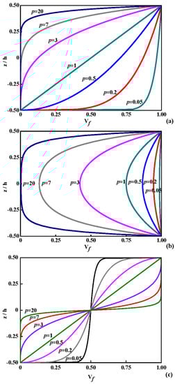
Figure 4.
Variation of ceramic volume fraction Vf through the coordinate-thickness ratio in various types: (a) P-OFG; (b) C-OFG; and (c) S-OFG.
3.3. Fundamental Frequencies Analysis
In this subsection, the relations between fundamental frequencies f (Hz) and gradient index p with general boundary restraints for P-, C- and S-OFG plates are contrasted and analyzed. The variation of the fundamental frequencies f (Hz) through gradient index p for OFG plates with h/a = 0.3 is shown in Figure 5. SSSS, SSSF, SSSC, CFCC, CFCS and CFCF boundary restraints are studied for P-, C- and S-OFG plates.
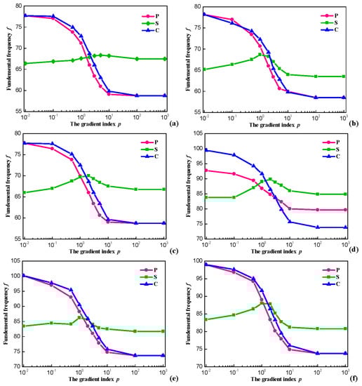
Figure 5.
Variation of the frequencies through p for OFG plates with h/a = 0.5: (a) OFG plates with SSSS; (b) OFG plates with SSSF; (c) OFG plates with SSSC; (d) OFG plates with CFCC; (e) OFG plates with CFCS; and (f) OFG plates with CFCF.
The six sets of curves show a similar behavior. For P- and C-OFG, the frequency parameters are considerably decreased by increasing the gradient index p. This is because Em is much smaller than Ef and the stiffness of the plate decreases with the increased distribution range of metal, thus the frequency parameter declines. When the value of p equals to zero, a complete ceramic plate is obtained, whereas infinity p indicates a complete metal plate. For the case of S-OFG, although there is a small range of fluctuations as p changes, the interval of fundamental frequencies f (Hz) is not large. Without loss of generality, the ceramic volume fraction always exhibits the opposite changes and the effect of p on the stiffness is small. Therefore, p has little influence on the fundamental frequencies f (Hz) with different boundary restraints overall.
Based on the above analysis, the fundamental frequencies f (Hz) for OFG plates with respect to gradient index p and volume fractions with simply supported boundary restraint are presented in Figure 6. It can be seen that, with the increase of V2-V1, the variation of fundamental frequencies f (Hz) through the gradient index p is more obvious for OFG plates. The results in Figure 6 show that the effects of the gradient index p on the fundamental frequencies f (Hz) vary with ceramic volume fractions between bottom and top surfaces.
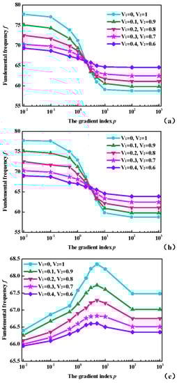
Figure 6.
Variation of the fundamental frequencies f (Hz) through p with simply supported boundary restraint in various types: (a) P-OFG; (b) C-OFG; and (c) S-OFG.
4. Conclusions
In this investigation, a modified Fourier series method has been applied to solve the free vibrations of moderately thick OFG plates with general boundary restraints. Displacements and rotations of each plate, regardless of boundary restraints, are described as an improved form of double Fourier cosine series and several auxiliary functions to effectively eliminate any possible jumps with the original displacement function and its relevant derivatives at the boundaries. Exact solutions are obtained by the energy functions of the plates based on Rayleigh–Ritz method. The general boundary restraints are achieved by setting the stiffness of springs without requiring any special procedures or schemes. It is shown that the present method has high reliability and accuracy. Numerous new results for moderately thick OFG plates with general boundary restraints are presented, which may serve as benchmark solutions for future research in this field.
A comprehensive investigation focused on free vibration properties of OFG materials is given, which serves as a supplement of the properties of FGMs. It is shown that vibration frequencies of the OFG plates are strongly influenced by the ceramic-to-metal volume distribution, gradient index, geometric parameter and boundary restraint. With the interval of ceramic volume fraction increases, the variation of fundamental frequencies through the gradient index is more obvious. When the interval of volume fraction is certain, S-OFG is less affected by the gradient index, while the vibration frequencies of P- and C-OFG are significantly influenced by the gradient index. The effects of the gradient index on the volume fraction are also discussed as well.
Acknowledgments
This investigation is financially supported by the National Natural Science Foundation of China (NSFC) (Grant No. 51675112), and the Fundamental Research Funds for the Central Universities (HEUCFP201733).
Author Contributions
Y.F., J.Y. and Z.W. initiated the idea. Y.F. and Z.W. wrote the main manuscript. Y.F. and G.Z. discussed and analyzed the results. All authors participated in refining the submitted manuscript.
Conflicts of Interest
The authors declare no conflict of interest.
Appendix A
Fourier coefficients eigenvector G, stiffness matrix K and mass matrix M of the moderately thick plates:
The unknown Fourier coefficients eigenvector G in the displacement expressions is divided into five parts: .
Sub-matrices in the K and M are listed as follows:
References
- Xiao, H.T.; Yue, Z.Q. Stresses and Displacements in Functionally Graded Materials of Semi-Infinite Extent Induced by Rectangular Loadings. Materials 2012, 5, 210–226. [Google Scholar] [CrossRef] [PubMed]
- Lima, D.D.; Mantri, S.A.; Mikler, C.V.; Contieri, R.; Yannetta, C.J.; Campo, K.N.; Lopes, E.S.; Styles, M.J.; Borkar, T.; Caram, R.; et al. Laser additive processing of a functionally graded internal fracture fixation plate. Mater. Des. 2017, 130, 8–15. [Google Scholar] [CrossRef]
- Shi, Z.Y.; Yao, X.L.; Pang, F.Z.; Wang, Q.S. An exact solution for the free-vibration analysis of functionally graded carbon-nanotube-reinforced composite beams with arbitrary boundary conditions. Sci. Rep. 2017, 7, 18. [Google Scholar] [CrossRef] [PubMed]
- Tornabene, F.; Fantuzzi, N.; Bacciocchi, M. Linear Static Behavior of Damaged Laminated Composite Plates and Shells. Materials 2017, 10, 811. [Google Scholar] [CrossRef] [PubMed]
- Sekkal, M.; Fahsi, B.; Tounsi, A.; Mahmoud, S.R. A novel and simple higher order shear deformation theory for stability and vibration of functionally graded sandwich plate. Steel Compos. Struct. 2017, 25, 389–401. [Google Scholar]
- Shabana, Y.M.; Noda, N. Thermo-elasto-plastic stresses of functionally graded material plate with a substrate and a coating. J. Therm. Stress. 2002, 25, 1133–1146. [Google Scholar] [CrossRef]
- Chen, Y.M.; Chen, G.; Xie, X.P. Weak Galerkin finite element method for Biot's consolidation problem. J. Comput. Appl. Math. 2018, 330, 398–416. [Google Scholar] [CrossRef]
- Sidhoum, I.A.; Boutchicha, D.; Benyoucef, S.; Tounsi, A. An original HSDT for free vibration analysis of functionally graded plates. Steel Compos. Struct. 2017, 25, 735–745. [Google Scholar]
- Dinh, D.N.; Nguyen, P.D. The Dynamic Response and Vibration of Functionally Graded Carbon Nanotube-Reinforced Composite (FG-CNTRC) Truncated Conical Shells Resting on Elastic Foundations. Materials 2017, 10, 1194. [Google Scholar] [CrossRef] [PubMed]
- Fallah, A.; Aghdam, M.M.; Kargarnovin, M.H. Free vibration analysis of moderately thick functionally graded plates on elastic foundation using the extended Kantorovich method. Arch. Appl. Mech. 2013, 83, 177–191. [Google Scholar] [CrossRef]
- Zhao, X.; Lee, Y.Y.; Liew, K.M. Free vibration analysis of functionally graded plates using the element-free kp-Ritz method. J. Sound Vib. 2009, 319, 918–939. [Google Scholar] [CrossRef]
- Dong, C.Y. Three-dimensional free vibration analysis of functionally graded annular plates using the Chebyshev-Ritz method. Mater. Des. 2008, 29, 1518–1525. [Google Scholar] [CrossRef]
- Ye, T.G.; Jin, G.Y.; Su, Z.; Jia, X.Z. A unified Chebyshev-Ritz formulation for vibration analysis of composite laminated deep open shells with arbitrary boundary conditions. Arch. Appl. Mech. 2014, 84, 441–471. [Google Scholar] [CrossRef]
- Vel, S.S.; Batra, R.C. Three-dimensional exact solution for the vibration of functionally graded rectangular plates. J. Sound Vib. 2004, 272, 703–730. [Google Scholar] [CrossRef]
- Ferreira, A.J.M.; Batra, R.C.; Roque, C.M.C.; Qian, L.F.; Jorge, R.M.N. Natural frequencies of functionally graded plates by a meshless method. Compos. Struct. 2006, 75, 593–600. [Google Scholar] [CrossRef]
- Ferreira, A.J.M.; Batra, R.C.; Roque, C.M.C.; Qian, L.F.; Martins, P. Static analysis of functionally graded plates using third-order shear deformation theory and a meshless method. Compos. Struct. 2005, 69, 449–457. [Google Scholar] [CrossRef]
- Vaghefi, R.; Baradaran, G.H.; Koohkan, H. Three-dimensional static analysis of thick functionally graded plates by using meshless local Petrov-Galerkin (MLPG) method. Eng. Anal. Bound. Elem. 2010, 34, 564–573. [Google Scholar] [CrossRef]
- Naskar, T.; Kumar, J. Predominant modes for Rayleigh wave propagation using the dynamic stiffness matrix approach. J. Geophys. Eng. 2017, 14, 1032–1041. [Google Scholar] [CrossRef]
- Rouzegar, J.; Abbasi, A. A refined finite element method for bending of smart functionally graded plates. Thin Walled Struct. 2017, 120, 386–396. [Google Scholar] [CrossRef]
- Nikbakht, S.; Salami, S.J.; Shakeri, M. Three dimensional analysis of functionally graded plates up to yielding, using full layer-wise finite element method. Compos. Struct. 2017, 182, 99–115. [Google Scholar] [CrossRef]
- Chi, S.H.; Chung, Y.L. Mechanical behavior of functionally graded material plates under transverse load—Part I: Analysis. Int. J. Solids Struct. 2006, 43, 3657–3674. [Google Scholar] [CrossRef]
- Chi, S.H.; Chung, Y.L. Mechanical behavior of functionally graded material plates under transverse load—Part II: Numerical results. Int. J. Solids Struct. 2006, 43, 3675–3691. [Google Scholar] [CrossRef]
- Qian, L.F.; Batra, R.C.; Chen, L.M. Static and dynamic deformations of thick functionally graded elastic plates by using higher-order shear and normal deformable plate theory and meshless local Petrov-Galerkin method. Compos. Part B Eng. 2004, 35, 685–697. [Google Scholar] [CrossRef]
- Liu, D.Y.; Wang, C.Y.; Chen, W.Q. Free vibration of FGM plates with in-plane material inhomogeneity. Compos. Struct. 2010, 92, 1047–1051. [Google Scholar] [CrossRef]
- Ramirez, F.; Heyliger, P.R.; Pan, E. Static analysis of functionally graded elastic anisotropic plates using a discrete layer approach. Compos. Part B Eng. 2006, 37, 10–20. [Google Scholar] [CrossRef]
- Zhang, W.; Yang, J.; Hao, Y.X. Chaotic vibrations of an orthotropic FGM rectangular plate based on third-order shear deformation theory. Nonlinear Dyn. 2010, 59, 619–660. [Google Scholar] [CrossRef]
- Huang, M.; Ma, X.Q.; Sakiyama, T.; Matuda, H.; Morita, C. Free vibration analysis of orthotropic rectangular plates with variable thickness and general boundary conditions. J. Sound Vib. 2005, 288, 931–955. [Google Scholar] [CrossRef]
- Li, W.L. Comparison of Fourier sine and cosine series expansions for beams with arbitrary boundary conditions. J. Sound Vib. 2002, 255, 185–194. [Google Scholar] [CrossRef]
- Li, W.L.; Zhang, X.F.; Du, J.T.; Liu, Z.G. An exact series solution for the transverse vibration of rectangular plates with general elastic boundary supports. J. Sound Vib. 2009, 321, 254–269. [Google Scholar] [CrossRef]
- Wang, Q.S.; Shi, D.Y.; Liang, Q.; Shi, X.J. A unified solution for vibration analysis of functionally graded circular, annular and sector plates with general boundary conditions. Compos. Part B Eng. 2016, 88, 264–294. [Google Scholar] [CrossRef]
- Ye, T.G.; Jin, G.Y.; Shi, S.X.; Ma, X.L. Three-dimensional free vibration analysis of thick cylindrical shells with general end conditions and resting on elastic foundations. Int. J. Mech. Sci. 2014, 84, 120–137. [Google Scholar] [CrossRef]
- Shi, D.Y.; Wang, Q.S.; Shi, X.J.; Pang, F.Z. A series solution for the in-plane vibration analysis of orthotropic rectangular plates with non-uniform elastic boundary constraints and internal line supports. Arch. Appl. Mech. 2015, 85, 51–73. [Google Scholar] [CrossRef]
- Xing, Y.F.; Liu, B. Exact solutions for the free in-plane vibrations of rectangular plates. Int. J. Mech. Sci. 2009, 51, 246–255. [Google Scholar] [CrossRef]
- Su, Z.; Jin, G.Y.; Ye, T.G. Vibration analysis and transient response of a functionally graded piezoelectric curved beam with general boundary conditions. Smart Mater. Struct. 2016, 25, 065003. [Google Scholar] [CrossRef]
- Jin, G.Y.; Ye, T.G.; Shi, S.X. Three-Dimensional Vibration Analysis of Isotropic and Orthotropic Open Shells and Plates with Arbitrary Boundary Conditions. Shock Vib. 2015, 2015, 896204. [Google Scholar] [CrossRef]
- Chen, Y.H.; Jin, G.Y.; Liu, Z.G. Free vibration analysis of circular cylindrical shell with non-uniform elastic boundary constraints. Int. J. Mech. Sci. 2013, 74, 120–132. [Google Scholar] [CrossRef]
- Dai, L.; Yang, T.J.; Du, J.T.; Li, W.L.; Brennan, M.J. An exact series solution for the vibration analysis of cylindrical shells with arbitrary boundary conditions. Appl. Acoust. 2013, 74, 440–449. [Google Scholar] [CrossRef]
- Zenkour, A.M. Generalized shear deformation theory for bending analysis of functionally graded plates. Appl. Math. Modell. 2006, 30, 67–84. [Google Scholar] [CrossRef]
- Hachemi, H.; Kaci, A.; Houari, M.S.A.; Bourada, M.; Tounsi, A.; Mahmoud, S.R. A new simple three-unknown shear deformation theory for bending analysis of FG plates resting on elastic foundations. Steel Compos. Struct. 2017, 25, 717–726. [Google Scholar]
- Erber, T. Hooke’s law and fatigue limits in micromechanics. Eur. J. Phys. 2001, 22, 491–499. [Google Scholar] [CrossRef]
- Gallistl, D.; Huber, P.; Peterseim, D. On the stability of the Rayleigh-Ritz method for eigenvalues. Numer. Math. 2017, 137, 339–351. [Google Scholar] [CrossRef]
© 2018 by the authors. Licensee MDPI, Basel, Switzerland. This article is an open access article distributed under the terms and conditions of the Creative Commons Attribution (CC BY) license (http://creativecommons.org/licenses/by/4.0/).