Article

A 3D MoS2/Graphene Microsphere Coated Separator for Excellent Performance Li-S Batteries

1
School of Materials Science and Engineering, Hebei University of Technology, Tianjin 300130, China
2
Synergy Innovation Institute of GDUT, Heyuan 517000, China
*
Authors to whom correspondence should be addressed.
Materials 2018, 11(10), 2064; https://doi.org/10.3390/ma11102064
Submission received: 24 August 2018 / Revised: 18 October 2018 / Accepted: 19 October 2018 / Published: 22 October 2018
(This article belongs to the Section Energy Materials)

Abstract

:
Lithium-sulfur (Li-S) batteries are the most prospective energy storage devices. Nevertheless, the poor conductivity of sulfur and the shuttling phenomenon of polysulfides hinder its application. In this paper, flower-like MoS2/graphene nanocomposite is prepared and deposited on a multi-functional separator to enhance the electrochemical behavior of Li-S batteries. The results demonstrated that the MoS2/graphene-coated separator is contributing to inhibit the shuttling phenomenon of polysulfides and improve the integrity of sulfur electrode. The initial discharge capacity of the battery using MoS2/graphene-coated separator at 0.2 C was up to 1516 mAh g−1. After 100 cycles, a reversible capacity of 880 mAh g−1 and a coulombic efficiency of 98.7% were obtained. The improved electrochemical behavior can be due to the nanostructure and Mo-S bond of the MoS2/graphene composite, which can combine physical shielding and chemisorption to prohibit the shuttle effect of polysulfides. The results prove that the MoS2/graphene-coated separator has the potential for feasible application in Li-S batteries to enhance their electrochemical performance.

1. Introduction

Lithium-sulfur (Li-S) battery exhibits enormous potential to be the next generation of low-cost and high-capacity batteries due to their high theoretical capacity (1675 mAh g−1), abundance reserves and eco-friendly nature [1,2]. With these merits, the commercial application of Li-S batteries, however, is still hindered due to the shuttling behavior of reduction compounds, the poor conductivities of sulfur, and the huge volume changes of the sulfur electrode in charge/discharge processes [3,4,5]. Among these deficiencies, the dissolution and diffusion of lithium polysulfides (LPS), which leads to the decrease of active materials utilization, capacity fading and self-discharge, seems to be the most challenging problem. Thus, the key point to develop Li-S batteries with excellent performance is preventing LPS shuttling in the electrolyte.
Multifarious strategies have been used to tackle this issue, such as integration of a conductive framework with sulfur [6,7,8,9,10], and optimization of the organic electrolyte [11,12]. Recently, much attention has been directed to incorporation of functional interlayers or multifunctional separators. The separator is used as an ionic conductor and electronic insulator in battery systems. Moreover, the electrolyte as well as polysulfides can pass through the separator and diffuse between the cathode and anode during the charge/discharge processes [13]. Multifunctional separators combine the barrier layer with the adsorption function layer into an integration structure, resulting in a superior performance than functional interlayers [14,15,16,17]. In addition, multi-functional separators offer the advantages of being inexpensive, of having high yield and also the viability of production on an industrial-scale. To date, there are several types of multi-functional separators, including carbon-modified separator [18,19], polymer-modified separator [20,21], oxide-modified separator [22], and metal sulfides-modified separator [23], that have been used in Li/S batteries. Compared with other modified methods, metal sulfides-modified separator has attracted more research attention because that metal–S bonds of metal sulfides do not only adsorb polysulfides dipolar via interaction on the polarized surface, but also, restrict polysulfides through the stronger S–S interaction. The previous literature has reported that the dissolution/diffusion of LPS can be significantly debased by the strong chemical bonding of sulfur to the metal sulfides, and the batteries exhibit an excellent capacity [24,25].
Herein, we designed and tested a MoS2/graphene composite fabricated on the pristine separator through slurry coating process to use as a functional separator for Li-S batteries, as shown in Figure 1. It has been demonstrated that graphene oxide possesses outstanding sulfur adsorption capability due to its oxygen-containing functional groups [26]. The introduction of the MoS2/graphene-coated separator can incorporate chemisorption and physical shielding to restrain shuttle effect, leading to enhanced cycling behavior of Li-S batteries. The battery using MoS2/graphene-coated separator delivers a specific capacity of 1516 mAh g−1 at 0.2 C in the first cycle and a reversible capacity of 880 mAh g−1 after 100 cycles. Compared to the battery using pristine separator, the batteries using MoS2/graphene composite separator present significantly enhanced electrochemical properties.

2. Materials and Methods

2.1. Preparation of Flower-Like MoS2

In a typical procedure, 0.88 g of Na2Mo4·2H2O and 1.4 g of H2NSCNH2 were dissolved in 50 mL ultrapure water with vigorously stir for 50 min. Then 2 M of HCl solution was added into the mixture to adjust the pH value to 1. Subsequently, the obtained solution was transferred into a 100 mL Teflon-lined autoclave and heated to 180 °C and kept for 24 h. Lastly, the resultant MoS2 was rinsed with ultrapure water to neutral and then dried under vacuum overnight.

2.2. Preparation of MoS2/Graphene Composite

First of all, graphene oxide (GO) was synthesized according to Hummers’ method and diluted by distilled water to obtain a GO suspension with the concentration of 2 mg mL−1 [27]. Then 1 g MoS2 powder was dispersed in 100 mL of GO suspension and 300 mL distilled water. The mixture was stirred for 1 h to form a well-distributed MoS2/GO suspension, which was further dried via a spray dryer with the solution feed rate of 5 mL min−1 at the inlet temperature of 200 °C. Finally, the obtained black powders were collected in a cyclone collector and further reduced to MoS2/reduced graphene oxide (RGO) by using hydrazine hydrate.

2.3. Preparation of MoS2/Graphene-Modified Separator

To fabricate MoS2/graphene-modified separator, a slurry was prepared with MoS2/graphene composite, carbon black and poly(vinylidene fluoride) (PVDF) in N-methylpyrrolidone (NMP) with a mass ratio of 8:1:1. The homogenous slurry was then pasted on a microporous membrane (Celgard 2400) which was employed here to provide mechanical strength. After drying at 70 °C under vacuum for 12 h, the MoS2/graphene-modified separator was stamped into round pieces with the size of 19 mm in diameter. The mass loading of the MoS2/graphene was 0.80 mg cm−2.

2.4. Synthesis of S/Graphene Cathode Material

To prepare the S/graphene cathode material, 50 mL GO suspension was sealed in a 100 mL Teflon-lined autoclave and maintained at 180 °C for 12 h. After cooling to room temperature, the as-prepared RGO suspension was freeze-dried in vacuum overnight to evaporate the water solvent. Afterwards, the black precipitate was ground into powder and then RGO was obtained. Then, RGO and sublimed sulfur were mixed in the weight ratio of 75:25 using ball milling method. Finally, the mixture was then transferred into a 10 mL Teflon-lined autoclave and further maintained at 155 °C for 12 h to obtain the S/graphene composite.

2.5. Material Characterization

The phase components of the composites were observed with X-ray diffraction (XRD, Rigaku S4800, Rigaku Corporation, Tokyo, Japan) measurement. The X-ray photoelectron spectroscopy (XPS, K-Alpha1063, Thermo Scientific, Waltham, MA, USA) was employed to investigate the compositions of the MoS2/graphene-modified separator before and after cycling. The morphology of the samples was explored by transmission electron microscopy (TEM, JEM-2100F, JEOL, Tokyo, Japan) and scanning electronic microscope (SEM, Supra 55, ZEISS, SUPRA, Jena, Germany) equipped with an energy dispersive spectroscopy (EDS) system. The dynamic mechanical analysis (DMA, Q800, TA Instruments, New Castle, DE, USA) was used to measure the tensile strain of the separators.

2.6. Electrochemical Measurements

The cathode was prepared as follows. The sulfur/graphene composite, carbon black and PVDF (8:1:1 wt ratio) were mixed with NMP as the solvent. After grinding for 60 min, the resultant slurry was tape-cased onto aluminum foil. After drying at 60 °C under vacuum for 10 h, the obtained composite covered electrode was stamped into disks with diameter of 14 mm. The evaluation of electrochemical performance was carried out in CR2032-type coin cells and the assembly of cells was finished in an Ar-filled glovebox (MBraun, Garching, Germany). The lithium foils served as the counter electrodes. For the electrolyte, 1 M lithium bis(trifluorometha-nesulfone)imide (LiTFSI) and 0.1 M LiNO3 dissolved in the mixture of dioxolane (DOL) and 1,2-dimethoxyethane (DME) (1:1 ratio vol%) were employed. The MoS2/graphene-modified separator was inserted between the cathode and the lithium foil with the MoS2/graphene coated side of the separator facing the cathode. The pristine Celgard 2400 was also used for comparison. The galvanostatic cycling experiments were conducted on a battery cycler (Neware, Shenzhen, China) with a cut-off potential of 1.7–2.8 V (vs. Li+/Li). Cyclic voltammetry (CV) was tested on a CHI611C potentiostat (Shanghaichenhua, Shanghai, China) within the voltage range of 1.7–2.8 V with a scan rate of 0.1 mV s−1. Electrochemical impedance spectroscopy (EIS) was performed on a CHI611C potentiostat in the frequency range of 100 kHz–0.01 Hz.

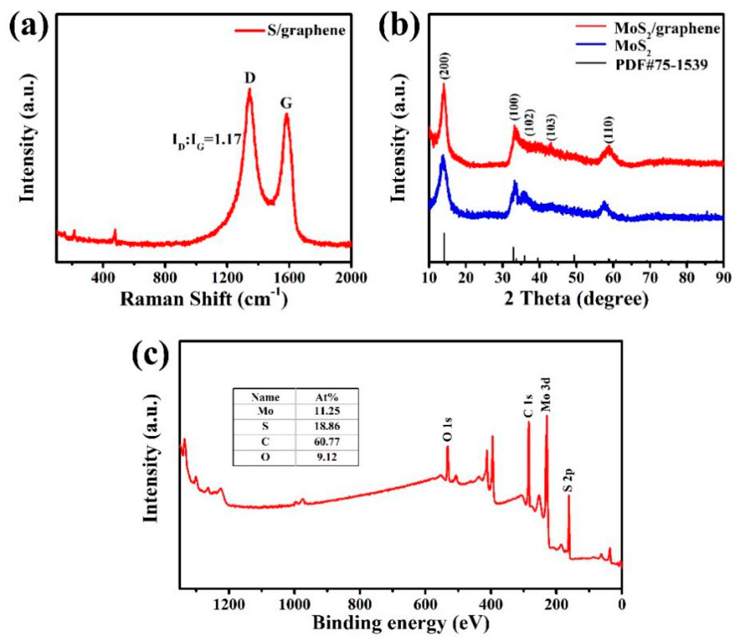
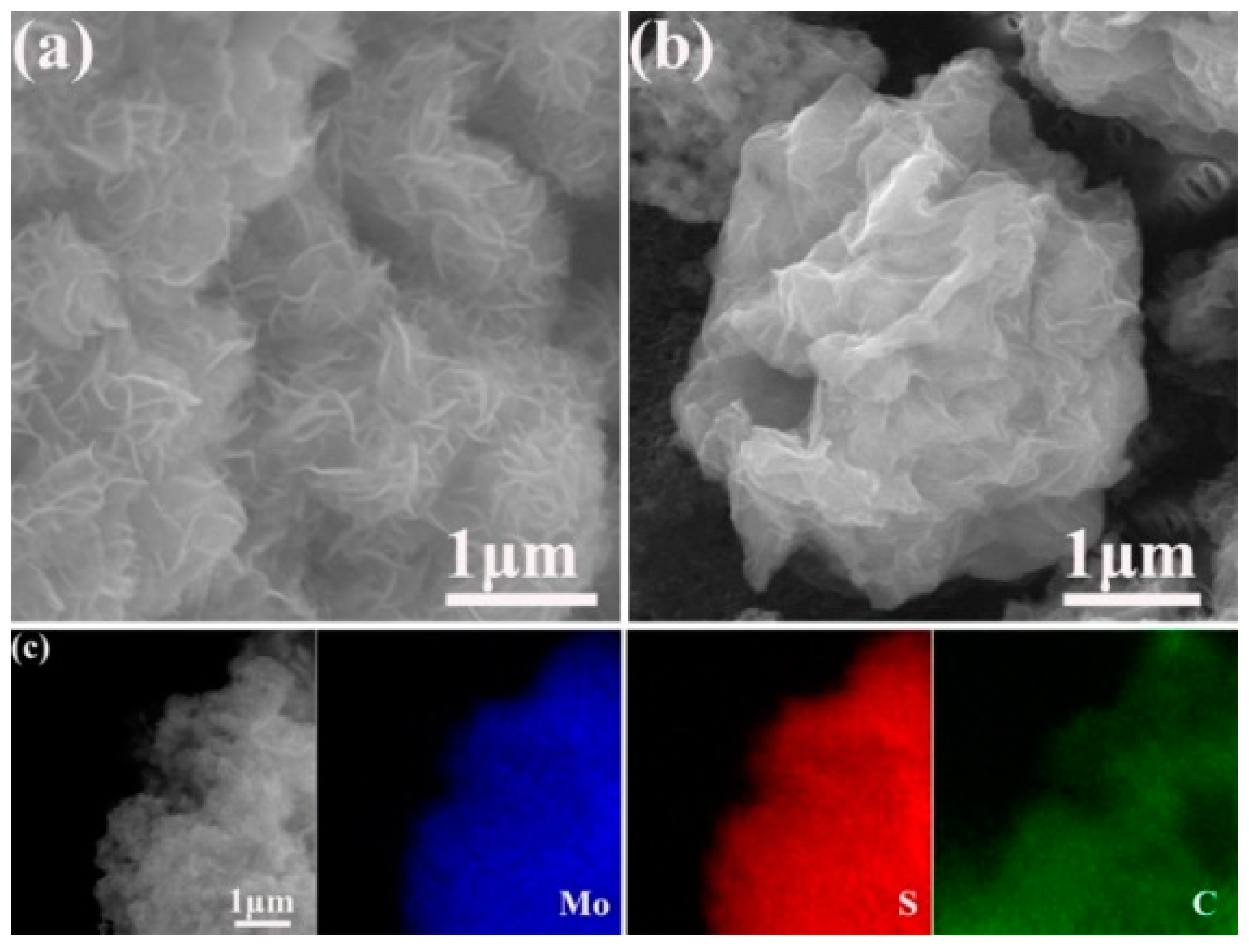
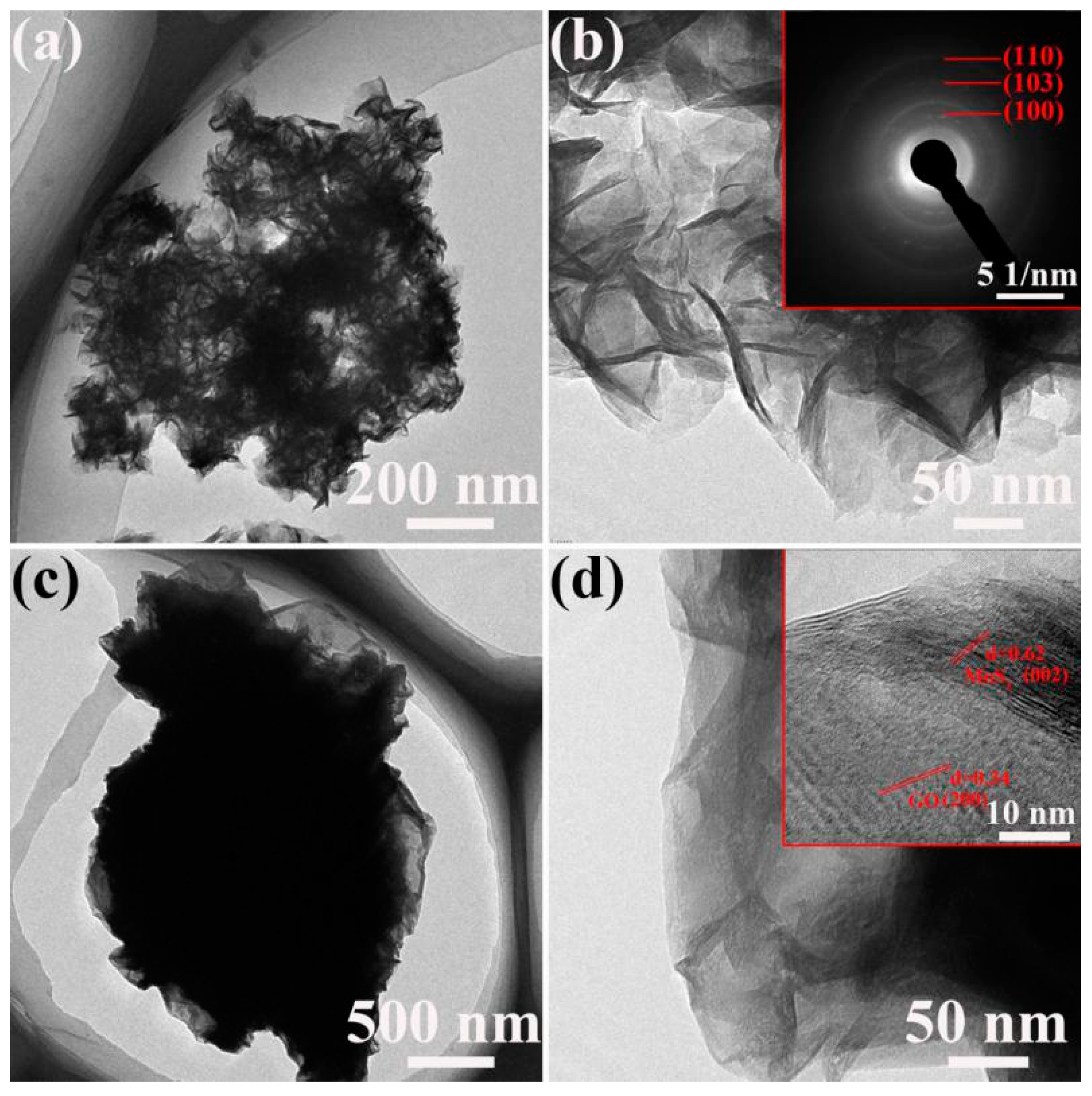
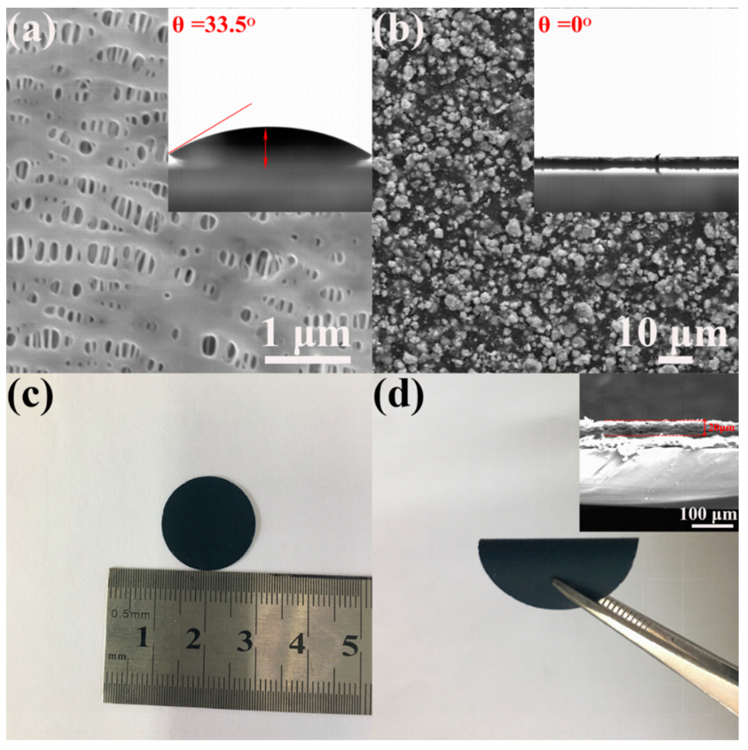
3. Results and Discussion

Raman characterization of S/graphene composite was shown in Figure 2a to confirm its composition. The Raman spectrum presents two major peaks at ca. 1344 and 1582 cm−1, which correspond with the D band and G band of graphene, respectively. Moreover, D band is corresponding to the disordered sp3 structure and G band is assigned to the sp2 hybridized graphitic structure. The ID/IG value of S/graphene is 1.17, indicating a highly defective graphite structure, which is beneficial to fast electron transfer [28]. Moreover, there are three characteristic Raman peaks of sulfur at 150, 215 and 477 cm−1, indicating the inclusion of sulfur in the composite [29].
As presented in Figure 2b, the crystal structure of MoS2 and MoS2/graphene composite were characterized using X-ray diffraction (XRD). There are five similar diffraction peaks observed in two samples. According to the standard Powder Diffraction File (PDF) files of #75-1539, conspicuous peaks at 14.0°, 33.4°, 36.2°, 43.6° and 58.1° are indexed to (002), (100), (102), (103) and (110) planes of crystalline MoS2 respectively, indicating that the crystal structure of MoS2 was efficiently retained in the spray drying process. The peak of graphene was not obtained.
XPS measurements were performed to investigate the surface chemical composition of the composite. The full spectrum in Figure 2c portrays the existence of Mo, S, C and O and the mass percentages of Mo, S, C and O are 11.25%, 18.86%, 60.77%, 9.12% respectively. The relatively high C content and low Mo content indicate that MoS2 has been coated by graphene, which was further demonstrated by SEM and TEM results.
The morphology of as-prepared MoS2 and MoS2/graphene composite is revealed by SEM images and energy dispersive X-ray spectroscopy (EDS) mapping. As presented in Figure 3a, the as-prepared MoS2 exhibits a flower-like structure with the average size of around 1.1 μm in diameter. The flower-like structure consisted of nanosheets with the thickness of around 30 nm. Figure 3b reveals that the MoS2 nanospheres were effectively wrapped by graphene, and the three-dimensional flower-like structure was remained in MoS2/graphene composite. However, the diameter of the MoS2/graphene sphere is about 3.2 μm, which is much larger than that of MoS2. EDS mapping of Mo, S and C elements in Figure 3c shows uniform distribution of three elements in the whole structure, confirming that MoS2 and graphene are tightly bonded.
The insight into inner structure of the samples was provided by transmission electron microscopy (TEM) analysis. Figure 4a,b shows the structure of as-prepared MoS2. The flower-like structure is clearly observed from the wrinkles. The inset of Figure 4b presents selected area electron diffraction (SAED) with distinct ring pattern, revealing the crystalline nature of MoS2. Figure 4c,d show the structure of MoS2/graphene composite, revealing that some nanospheres of MoS2 are well wrapped by thin graphene sheets. As illustrated by the HRTEM image in the inset of Figure 4d, the spacing between the adjacent fringes can be resolved to be 0.62 nm and 0.34 nm, corresponding to the (002) planar spacing of MoS2 and (200) planar spacing of graphene, respectively. The results indicate a strong interfacial bonding between graphene and MoS2, which can shorten electron/ion transport passage and supply more adsorption surfaces.
The surface morphologies of the pristine and MoS2/graphene-coated separators are investigated by SEM. As presented in Figure 5a, the surface of pristine separator is flat and nanoporous. The size of pores was around 100 nm in diameter, which can effectively guarantee the rapid transfer of ions and achieve the diffusion of polysulfides to anode [30,31]. Moreover, the wetting ability of the separators was tested with contact angle measurement. The inset in Figure 5a exhibits that the contact angle of the pristine separator is 33.5°. Figure 5b shows the surface morphology of the MoS2/graphene-coated separator. Uniform MoS2/graphene spheres with the average size of 3.6 μm in diameter were observed. The contact angle of the MoS2/graphene-coated separator is 0° as shown in the inset in Figure 5b, suggesting the excellent wetting properties of the composite separator. The images of MoS2/graphene-coated separator with tiled and folded state are exhibited in Figure 5c,d respectively. The separator shows a preeminent flexibility, which can guarantee the close contact between the surface of the sulfur cathode and the separator. The cross-section of the MoS2/graphene-coated separator (inset of Figure 5d) reveals good adhesion of MoS2/graphene composite to the surface of the pristine separator, and composite layer shows a thickness of around 20 μm.
The tensile property was measured to the mechanical properties of pristine separator and MoS2/graphene-coated separator. As shown in Figure 6, the elasticity modulus of pristine separator and MoS2/graphene-coated separator are calculated from curves to be 0.202 and 0.203, respectively. It is evident that the coating of MoS2/graphene on the surface of pristine separator does not affect the elasticity of the pristine separator. Notably, the tensile strength of MoS2/graphene-coated separator is 33 MPa, which is higher than that of the pristine separator, indicating the excellent elongation and mechanical properties. This can be attributed to the high flexibility property of the MoS2/graphene membrane.
The electrochemical measurements were performed to clarify the benefit of the MoS2/graphene-coated separator in enhancing the performance of Li-S batteries. The representative discharge/charge curves of the batteries with MoS2/graphene-coated separator and pristine separator between 1.7 and 2.8 V at 0.2 C are presented in Figure 7a,b. The profiles show two voltage plateaus upon discharging and one voltage plateau upon charging, which is consistent with the previous reports [32,33]. One can see that the discharge/charge curves of the batteries with MoS2/graphene-modified separator exhibit more steady voltage platforms and smaller capacity loss compared to the one with pristine separator. Meanwhile, ΔE for cells with pristine separator, which is 0.25 V, is larger than that for cells with MoS2/graphene-coated separator, which is 0.18 V. These results demonstrate that the MoS2/graphene-coated separator relieves the redox polarization in the batteries. The lowering of potential hysteresis can be attributed to the abundant electron/ions transport channels and huge adsorption surfaces provided by the strong interfacial bonding between MoS2 and graphene, which can effectively promote the transmission of electrons and ions to accelerate the kinetics processes of the electrochemical reactions [34].
Figure 7c shows the cycling capability of the batteries with different separators at 0.2 C. The batteries with the pristine separator exhibit the first discharge capacity of 1125 mAh g−1 and the 100th discharge capacity of 473 mAh g−1, which indicate a rapid decay of discharge capacity. The batteries with graphene-coated separator show slightly improvement on discharge capacity and cycling performance with the first discharge capacity of 1363 mAh g−1 and the 100th discharge capacity of 706 mAh g−1, resulting in a capacity retention of 51%. These improvements can be due to the high conductivity of the graphene-coated separator, which can effectively shorten the transport passage of electrons and ions. Notably, the batteries using the MoS2/graphene-coated separator possess much better cycling performance. The first discharge capacity increased to 1516 mAh g−1, indicating that the lithium polysulfides solved in the electrolyte is successfully intercepted by the MoS2/graphene-modified separator in the initial discharge process. After 100 cycles, the batteries using MoS2/graphene-coated separator maintain a capacity of over 880 mAh g−1. Moreover, the batteries with MoS2/graphene-coated separator also exhibit a higher coulombic efficiency of about 98.7%.
The rate capability comparison of the batteries using different separators was also investigated. As shown in Figure 7d, the battery using the pristine separator exhibits a poor performance, which delivers 1197, 878, 632, 533, 420, 235 mAh g−1 at 0.2 C, 0.5 C, 1 C, 2 C, 3 C and 4 C, respectively. Moreover, the rate capability of the battery using the graphene-coated separator shows a modified performance due to the excellent conductivity of graphene-coated separator, which delivers 1391, 992, 732, 631, 542, 395 mAh g−1 at 0.2 C, 0.5 C, 1 C, 2 C, 3 C and 4 C, respectively. By contrast, the battery using the MoS2/graphene-modified separator possesses much enhanced rate capability with the initial discharge capacity of 1618 mAh g−1 at 0.2 C, which was much higher than batteries with graphene-coated separator and pristine separator. After that, the capacity gradually decreases and stabilizes at around 1382 mAh g−1. Furthermore, the battery with MoS2/graphene-modified separator delivers high reversible capacities of 1163, 1009, 860, 770 and 671 mAh g−1 at the rate 0.5 C, 1 C, 2 C, 3 C and 4 C, respectively. Notably, after the rate reverted to 0.2 C, a high capacity of 1130 mAh g−1 is recovered. The significantly enhanced electrochemical performance can be ascribed to the three-dimensional flower-like MoS2/graphene composite, which are beneficial for fast transport of ion/electronic as well as increase the liquid electrolyte storage capacity.
Figure 7e exhibits the initial three cyclic voltammetry (CV) profiles of batteries using MoS2/graphene-coated separator. Two reduction peaks at 2.1 and 2.4 V are detected, which can be ascribed to the formation of sulfur to long chain polysulfides and then to Li2S/Li2S2. The only oxidation peak at 2.4 V is corresponding to the reverse conversion of Li2S/Li2S2 into the polysulfides as well as elemental sulfur. The CV profiles in the subsequent scans show no distinct change of the peak position and intensity, suggesting an outstanding electrochemical stability of the batteries. However, for CV profiles of batteries with the pristine separator, the intensity of the peaks shows obvious decrease, indicating larger polarization in the batteries, as shown in Figure 7f. Moreover, the loop area of the battery with MoS2/graphene-modified separator is larger than that of the one with the pristine separator, suggesting the high utilization of sulfur for energy storage using the MoS2/graphene-coated separator [35].
To study the kinetics process, EIS measurements for the batteries with pristine separator and MoS2/graphene-coated separator were performed. As presented in Figure 8, both Nyquist plots are composed with a semicircle in high frequency region and an inclined line in the low-frequency region, which are in connection with the charge-transfer resistance and Li+ diffusion, respectively. Notably, the batteries with MoS2/graphene-coated separator shows much lower charge transfer resistance than the battery with the pristine separator (89 Ω versus 135 Ω). The lower resistance of the batteries with MoS2/graphene-coated separator results from decreased insulating materials deposited on the surface of the electrode, leading to an excellent cycling stability.
Since the self-discharge is one of the major defects of Li-S batteries, the self-discharge behavior of the electrodes with the MoS2/graphene-coated separator and the pristine separator were characterized. The batteries were rested for 72 h after the 10th cycle at 0.2 C. Figure 9a shows the open-circuit voltage profiles of both cells. One can see that the voltage for the battery with the pristine separator obviously dropped from 2.26 to 2.11 V during the rest time, indicating the significant reduction of the polysulfides from high-order to low-order. However, the voltage of the battery using the MoS2/graphene-modified separator shows a small attenuation from 2.3 to 2.26 V during the rest time, indicating the effective suppression of the self-discharge by the composite separator. Figure 9b shows the cycling performance of the electrodes after the 72 h rest. The original capacity of the battery using a pristine separator was significantly reduced by 42.1%. In contrast, the battery using a MoS2/graphene-coated separator exhibited a decline rate of 13.52%.
The morphology of the MoS2/graphene-coated separator after 100 cycles at 0.2 C is detected and the results are exhibited in Figure 10a,b. Compared with the data before cycling in Figure 3, the surface was slightly damaged, and the MoS2/graphene composite still remain uniform distribution on the surface, indicating that the coating is flexible and tightly coated to avoid dropping out from the separator during cycles. No obvious cluster was observed and the diameter of the MoS2/graphene sphere is about 4 μm. The corresponding EDS elemental maps (Figure 10c) further reveal that the Mo, S and C are distributed homogenously across the whole structure after cycles, suggesting that the composite coating acted as a filter for absorbing the dissolved polysulfides.
XPS S 2p spectrum of the MoS2/graphene-coated separator after 100 cycles at 0.2 C was presented in Figure 11 to verify the interaction between polysulfides and the MoS2/graphene-modified separator. Here the peaks between 169.8 and 168.7 eV are assigned to the sulfates, which can be attributed to brief air exposure of the sample in the XPS loading process. Furthermore, the peaks at 163.0 and 161.7 eV prove the existence of polysulfides in the MoS2/graphene-modified separator, consistent with the previous SEM results. Therefore, we believe that the migrating polysulfide species can diffuse through the MoS2/graphene-modified separator and be effectively captured during cycling.

4. Conclusions

In summary, a multi-functional separator modified by MoS2/graphene composite is synthesized on the routine separator via slurry coating process to substantially enhance the electrochemical capability of Li-S battery. The MoS2/graphene-coated separator serves as a high efficiency ionic sieve that can block the transportation of the polysulfide anions and effectively decreases the shuttle effect. In addition, the introduction of MoS2/graphene-coated separator possessed higher sulfur utilization as a result of the recycling of entrapped active materials. These advantages can significantly improve the specific capacity and cycling stability of battery, with an initial discharge capacity of 1516 mAh g−1 and a higher reversible capacity of 880 mAh g−1 with coulombic efficiency of 98.7% after 100 cycles at 0.2 C. Therefore, the separator modification by MoS2/graphene composite will provide an effective method to suppress the shuttling phenomenon and enhance the electrochemical capability of Li-S batteries.

Author Contributions

Formal Analysis, J.Z., H.L. and T.T.; Investigation, J.Z. and S.Y.; Writing, Original Draft Preparation, S.Y., N.L. and Y.Z.; Writing, Review and Editing, Y.Z., H.L. and T.T.; Supervision, Y.Z.; Project Administration, N.L and H.L.

Funding

This research was funded by National Natural Science Foundation of China [grant number 51505122].

Conflicts of Interest

The authors declare no conflict of interest.

References

  1. Ji, X.; Lee, K.T.; Nazar, L.F. A highly ordered nanostructured carbon-sulphur cathode for lithium-sulfur batteries. Nat. Mater. 2009, 8, 500–506. [Google Scholar] [CrossRef] [PubMed]
  2. Zhang, X.; Xie, H.; Kim, C.S.; Zaghib, K.; Mauger, A.; Julien, C. Advances in lithium-sulfur batteries. Mater. Sci. Eng. R 2017, 121, 1–29. [Google Scholar] [CrossRef]
  3. Li, S.H.; Xia, X.H.; Wang, Y.D.; Wang, X.L.; Tu, J.P. Reconstruction of multidimensional carbon hosts with combined 0D, 1D and 2D networks for enhanced lithium-sulfur batteries. J. Power Sources 2017, 342, 224–230. [Google Scholar] [CrossRef]
  4. Chen, S.; Gao, Y.; Yu, Z.; Gordin, M.L.; Song, J.; Wang, D. High capacity of lithium-sulfur batteries at low electrolyte/sulfur ratio enabled by an organosulfide containing electrolyte. Nano Energy 2017, 31, 418–423. [Google Scholar] [CrossRef]
  5. Urbonaite, S.; Poux, T.; Novák, P. Progress towards Commercially Viable Li-S Battery Cells. Adv. Energy Mater. 2015, 5, 1500118–1500137. [Google Scholar] [CrossRef]
  6. Fang, R.; Zhao, S.; Hou, P.; Cheng, M.; Wang, S.; Cheng, H.; Liu, C.; Li, F. 3D Interconnected Electrode Materials with Ultrahigh Areal Sulfur Loading for Li-S Batteries. Adv. Mater. 2016, 28, 3374–3382. [Google Scholar] [CrossRef] [PubMed]
  7. Hou, Y.; Li, J.; Gao, X.; Wen, Z.; Yuan, C.; Chen, J. 3D Dual-Confined Sulfur Encapsulated in Porous Carbon Nanosheets and Wrapped with Graphene Aerogels as Cathode for Advanced Lithium Sulfur Batteries. Nanoscale 2016, 8, 8228–8235. [Google Scholar] [CrossRef] [PubMed]
  8. Shukla, S.; Ghosh, A.; Sen, U.K.; Roy, P.K.; Mitra, S.; Lochab, B. Cardanol Benzoxazine-Sulfur Copolymers for Li-S batteries: Symbiosis of Sustainability and Performance. ChemistrySelect 2016, 1, 594–600. [Google Scholar] [CrossRef]
  9. Zhou, G.; Li, L.; Wang, D.; Shan, X.; Pei, S.; Li, F.; Cheng, H. A Flexible Sulfur-Graphene-Polypropylene Separator Integrated Electrode for Advanced Li-S Batteries. Adv. Mater. 2015, 27, 641–647. [Google Scholar] [CrossRef] [PubMed]
  10. Li, H.; Wei, Y.; Ren, J.; Zhang, W.; Zhang, C.; Zhang, Y. Three-dimensionally ordered hierarchically porous polypyrrole loading sulfur as high-performance cathode for lithium/sulfur batteries. Polymer 2018, 137, 261–268. [Google Scholar] [CrossRef]
  11. Hagen, M.; Fanz, P.; Tübke, J. Cell energy density and electrolyte/sulfur ratio in Li-S cells. J. Power Sources 2014, 264, 30–34. [Google Scholar] [CrossRef]
  12. Safa, M.; Hao, Y.; Chamaani, A.; Adelowo, E.; Chawla, N.; Wang, C.; El-Zahab, B. Capacity fading mechanism in lithium-sulfur battery using poly(ionic liquid) gel electrolyte. Electrochim. Acta 2017, 258, 1284–1292. [Google Scholar] [CrossRef]
  13. Zhang, Z.Y.; Lai, Y.Q.; Zhang, Z.A.; Li, J. A functional carbon layer-coated separator for high performance lithium sulfur batteries. Solid State Ionics 2015, 278, 166–171. [Google Scholar] [CrossRef]
  14. Chung, S.H.; Manthiram, A. High-performance Li-S batteries with an ultra-lightweight MWCNT-coated separator. J. Phys. Chem. C 2014, 5, 1978–1983. [Google Scholar] [CrossRef] [PubMed]
  15. Singhal, R.; Chung, S.H.; Manthiram, A.; Kalra, V. A free-standing carbon nanofiber interlayer for high-performance lithium-sulfur batteries. J. Mater. Chem. A 2015, 3, 4530–4538. [Google Scholar] [CrossRef]
  16. Huang, J.Q.; Zhuang, T.Z.; Zhang, Q.; Peng, H.J.; Chen, C.M.; Wei, F. Permselective graphene oxide membrane for highly stable and anti-self-discharge lithium sulfur batteries. ACS Nano 2015, 9, 3002–3011. [Google Scholar] [CrossRef] [PubMed]
  17. Huang, J.Q.; Zhang, Q.; Wei, F. Multi-functional separator/interlayer system for high stable lithium-sulfur batteries: Progress and prospects. Energy Storage Mater. 2015, 1, 127–145. [Google Scholar] [CrossRef]
  18. Chung, S.; Manthiram, A. Bifunctional Separator with a Light-Weight Carbon-Coating for Dynamically and Statically Stable Lithium-Sulfur Batteries. Adv. Funct. Mater. 2014, 24, 5299–5306. [Google Scholar] [CrossRef]
  19. Lin, W.; Chen, Y.; Li, P.; He, J.; Zhao, Y.; Wang, Z.; Liu, J.; Qi, F.; Zheng, B.; Zhou, J.; et al. Enhanced Performance of Lithium Sulfur Battery with a Reduced Graphene Oxide Coating Separator. J. Electrochem. Soc. 2015, 162, A1624–A1629. [Google Scholar] [CrossRef]
  20. Conder, J.; Urbonaite, S.; Streich, D.; Novák, P.; Gubler, L. Taming the polysulphide shuttle in Li-S batteries by plasma-induced asymmetric functionalisation of the separator. RSC Adv. 2015, 5, 79654–79660. [Google Scholar] [CrossRef]
  21. Kim, J.S.; Hwang, T.H.; Kim, B.G.; Min, J.; Choi, J.W. A Lithium-Sulfur Battery with a High Areal Energy Density. Adv. Funct. Mater. 2014, 24, 5359–5367. [Google Scholar] [CrossRef]
  22. Li, W.; Hicksgarner, J.; Wang, J.; Liu, J.; Gross, A.F.; Sherman, E.; Graetz, J.; Vajo, J.J.; Liu, P. V2O5 Polysulfide Anion Barrier for Long-Lived Li-S Batteries. Chem. Mater. 2014, 26, 3403–3410. [Google Scholar] [CrossRef]
  23. Yan, L.; Luo, N.; Kong, W.; Luo, S.; Wu, H.; Jiang, K.; Li, Q.; Fan, S.; Duan, W.; Wang, J. Enhanced performance of lithium-sulfur batteries with an ultrathin and lightweight MoS2/carbon nanotube interlayer. J. Power Sources 2018, 389, 169–177. [Google Scholar] [CrossRef]
  24. Xu, H.; Manthiram, A. Hollow cobalt sulfide polyhedra-enabled long-life, high areal-capacity lithium-sulfur batteries. Nano Energy 2017, 33, 124–129. [Google Scholar] [CrossRef]
  25. Yang, W.; Zhao, H.; Chen, L.; Fang, C.; Rui, Z.; Yang, L.; Wan, H.; Liu, J.; Zhou, Y.; Wang, P.; et al. Ferrous sulfide-assisted hollow carbon spheres as sulfur host for advanced lithium-sulfur batteries. Chem. Eng. J. 2017, 36, 1040–1047. [Google Scholar] [CrossRef]
  26. Zeng, Q.; Leng, X.; Wu, K.H.; Gentle, I.R.; Wang, D.W. Electroactive cellulose-supported graphene oxide interlayers for Li-S batteries. Carbon 2015, 96, 611–619. [Google Scholar] [CrossRef]
  27. Sun, L.; Fugetsu, B. Mass production of graphene oxide from expanded graphite. Mater. Lett. 2013, 109, 207–210. [Google Scholar] [CrossRef] [Green Version]
  28. Shi, J.; Wang, Y.; Su, Q.; Cheng, F.; Kong, X.; Lin, J.; Zhu, T.; Liang, S.; Pan, A. N-S co-doped C@SnS nanoflakes/graphene composite as advanced anode for sodium-ion batteries. Chem. Eng. J. 2018, 353, 606–614. [Google Scholar] [CrossRef]
  29. Chiochan, P.; Phattharasupakun, N.; Wutthiprom, J.; Suksomboon, M.; Kaewruang, S.; Suktha, P.; Sawangphruk, M. Core-double shell sulfur@carbon black nanosphere@oxidized carbon nanosheet composites as the cathode materials for Li-S batteries. Electrochim. Acta 2017, 237, 78–86. [Google Scholar] [CrossRef]
  30. Song, S.; Shi, L.; Lu, S.; Pang, Y.; Wang, Y.; Zhu, M.; Ding, D.; Ding, S. A new polysulfide blocker-poly(acrylic acid) modified separator for improved performance of lithium-sulfur battery. J. Membr. Sci. 2018, 563, 277–283. [Google Scholar] [CrossRef]
  31. Wang, Z.; Zhang, J.; Yang, Y.; Yue, X.; Hao, X.; Sun, W.; Rooney, D.; Sun, K. Flexible carbon nanofiber/polyvinylidene fluoride composite membranes as interlayers in high-performance Lithium Sulfur batteries. J. Power Sources 2016, 329, 305–313. [Google Scholar] [CrossRef]
  32. Xiao, Z.; Yang, Z.; Wang, L.; Nie, H.; Zhong, M.; Lai, Q.; Xu, X.; Zhang, L.; Huang, S. Lithium-Sulfur Batteries: A Lightweight TiO2/Graphene Interlayer, Applied as a Highly Effective Polysulfide Absorbent for Fast, Long-Life Lithium-Sulfur Batteries. Adv. Mater. 2015, 27, 2891–2898. [Google Scholar] [CrossRef] [PubMed]
  33. Rao, M.; Song, X.; Cairns, E.J. Nano-carbon/sulfur composite cathode materials with carbon nanofiber as electrical conductor for advanced secondary lithium/sulfur cells. J. Power Sources 2012, 205, 474–478. [Google Scholar] [CrossRef]
  34. Liao, H.; Zhang, H.; Hong, H.; Li, Z.; Lin, Y. Novel flower-like hierarchical carbon sphere with multi-scale pores coated on PP separator for high-performance lithium-sulfur batteries. Electrochim. Acta 2017, 257, 210–216. [Google Scholar] [CrossRef]
  35. Hoang, V.C.; Do, V.D.; Nah, I.W.; Lee, C.; Cho, W.I.; Oh, I.H. Facile Coating of Graphene Interlayer onto Li2S as a High Electrochemical Performance Cathode for Lithium Sulfur Battery. Electrochim. Acta 2016, 210, 1–6. [Google Scholar] [CrossRef]
Figure 1. The schematic illustration of polysulfide-trapping mechanism and cell configuration of the lithium-sulfur (Li-S) battery using (a) pristine separator and (b) MoS2/graphene-coated separator.
Materials 11 02064 g001
Figure 2. (a) Raman spectrum of S/graphene composite; (b) X-ray diffraction patterns of MoS2 and MoS2/graphene composite; (c) XPS spectrum of MoS2/graphene composite.
Materials 11 02064 g002
Figure 3. SEM images of (a) MoS2 and (b) MoS2/graphene composite; (c) EDS mapping of MoS2/graphene composite.
Materials 11 02064 g003
Figure 4. TEM images of (a,b) MoS2 and (c,d) MoS2/graphene composite.
Materials 11 02064 g004
Figure 5. SEM images of (a) pristine separator; (b) MoS2/graphene-coated separator (The insets are the contact angle of electrolyte on the surface of each separator); (c,d) Photographs of the MoS2/graphene-coated separator (inset is the image of MoS2/graphene-coated separator section).
Materials 11 02064 g005
Figure 6. The mechanical properties of (a) pristine separator and (b) MoS2/graphene-coated separator.
Materials 11 02064 g006
Figure 7. The discharge/charge voltage profiles of Li-S batteries with (a) MoS2/graphene-coated separator and (b) pristine separator at 0.2 C; (c) The cycling performance and (d) rate capability of Li-S batteries with MoS2/graphene-coated, graphene-coated and pristine separator; The cyclic voltammetry (CV) curves of the Li-S batteries with (e) MoS2/graphene-coated separator and (f) pristine separator.
Materials 11 02064 g007
Figure 8. The electrochemical impedance spectra of Li-S batteries using pristine separator and MoS2/graphene-coated separator.
Materials 11 02064 g008
Figure 9. Self-discharge behavior of the electrodes with the MoS2/graphene-coated separator and the pristine separator. The cells were rested for 72 h after the 10th cycle: (a) open-circuit voltage profiles during the rest time; (b) cycling performance of the electrodes.
Materials 11 02064 g009
Figure 10. (a,b) SEM images of the MoS2/graphene-coated separator after 100 cycles at 0.2 C and (c) the elemental mapping of Mo, S and C.
Materials 11 02064 g010
Figure 11. Ex-situ S 2p XPS spectra of the cycled MoS2/graphene-coated separator.
Materials 11 02064 g011

