Developing Lignosulfonate-Based Activated Carbon Fibers


Abstract
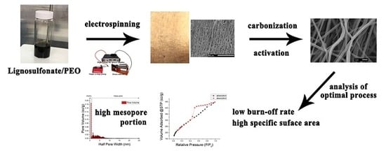
1. Introduction
2. Materials and Methods
2.1. Materials
2.2. Methods
2.2.1. Electrospinning
2.2.2. Production of Activated Carbon Fibers
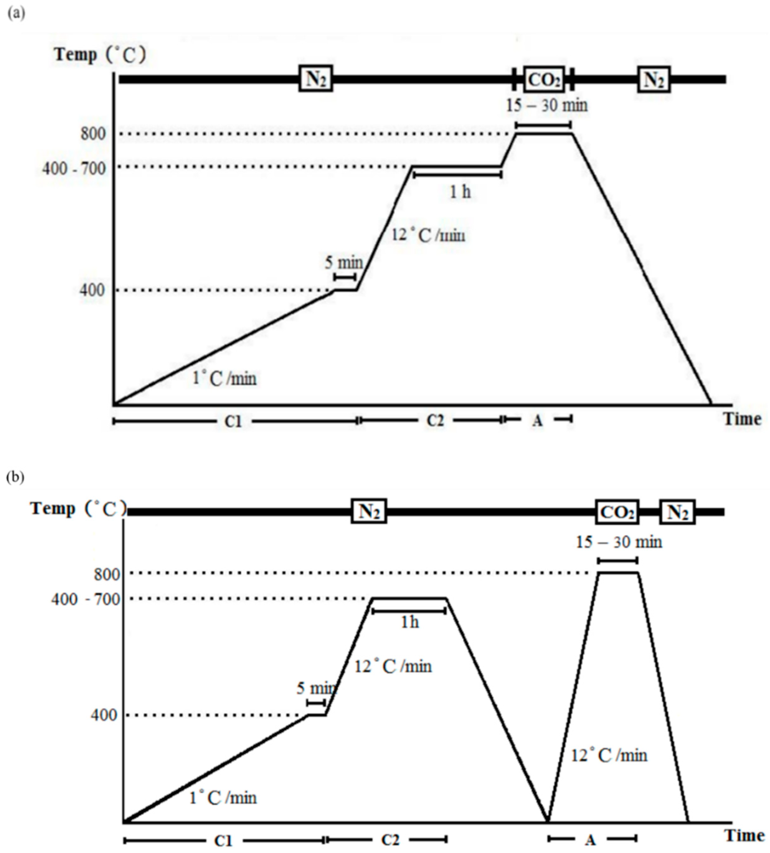
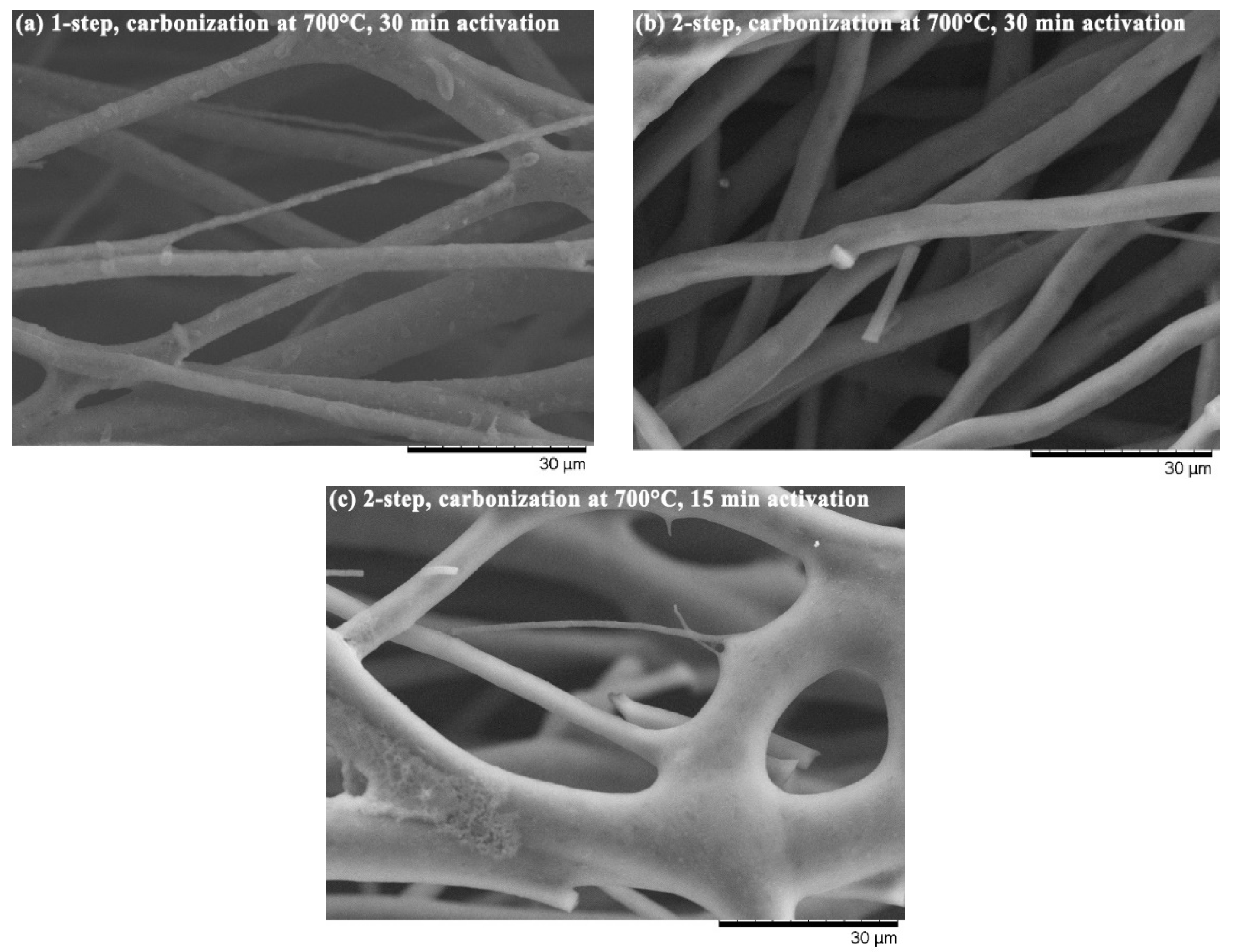
- One-step activation: the temperature increased to 800 °C after carbonization without cooling, and was maintained isothermally at 800 °C for 15 or 30 min in a CO2 environment, and then cooled to the ambient temperature in an N2 environment (Figure 2a).
- Two-step activation: a cooling procedure was conducted between carbonization and activation, in which the temperature was increased to 800 °C in N2 environment, and then kept in an isothermal CO2 environment (800 °C) for 15 or 30 min before finally cooled to ambient temperature in an N2 environment (Figure 2b).
2.2.3. Properties of Produced Activated Carbon Fibers
3. Results and Discussion
4. Conclusions
Author Contributions
Funding
Acknowledgments
Conflicts of Interest
References
- Marsh, H.; Rodríguez-Reinoso, F. Activated Carbon, 1st ed.; Elsevier: Amsterdam, The Netherlands, 2006; ISBN 9780080444635. [Google Scholar]
- Chae, H.G.; Choi, Y.H.; Minus, M.L.; Kumar, S. Carbon nanotube reinforced small diameter polyacrylonitrile based carbon fiber. Compos. Sci. Technol. 2009, 69, 406–413. [Google Scholar] [CrossRef]
- Walker, P.L., Jr.; Rusinko, J.F.; Austin, L.G. Gas Reactions of Carbon. Adv. Catal. 1959, 11, 133–221. [Google Scholar] [CrossRef]
- Rodríguez-Reinoso, F. The role of carbon materials in heterogeneous catalysis. Carbon 1998, 36, 159–175. [Google Scholar] [CrossRef]
- Lai, C.; Zhou, Z.; Zhang, L.; Wang, X.; Zhou, Q.; Zhao, Y.; Wang, Y.; Wu, X.F.; Zhu, Z.; Fong, H. Free-standing and mechanically flexible mats consisting of electrospun carbon nanofibers made from a natural product of alkali lignin as binder-free electrodes for high-performance supercapacitors. J. Power Sources 2014, 247, 134–141. [Google Scholar] [CrossRef]
- Huang, Y.; Liu, Y.; Zhao, G.; Chen, J.Y. Sustainable activated carbon fiber from sawdust by reactivation for high-performance supercapacitors. J. Mater. Sci. 2017, 52, 478–488. [Google Scholar] [CrossRef]
- Ralph, J.; Lundquist, K.; Brunow, G.; Lu, F.; Kim, H.; Schatz, P.F.; Marita, J.M.; Hatfield, R.D.; Ralph, S.A.; Christensen, J.H.; et al. Lignins: Natural polymers from oxidative coupling of 4-hydroxyphenyl-propanoids. Phytochem. Rev. 2004, 3, 29–60. [Google Scholar] [CrossRef]
- Walter, J.S. Lignin Biochemistry; Academic Press: Cambridge, MA, USA, 1965. [Google Scholar]
- Gellerstedt, G.; Sjöholm, E.; Brodin, I. The Wood-Based Biorefinery: A Source of Carbon Fiber? Open Agric. J. 2010, 4, 119–124. [Google Scholar] [CrossRef]
- Lora, J.H.; Glasser, W.G. Recent Industrial Applications of Lignin: A Sustainable Alternative to Nonrevewable Materials. J. Polym. Environ. 2002, 10, 39–48. [Google Scholar] [CrossRef]
- Otani, S.; Fukuoka, Y.; Igarashi, B.; Sasaki, K. Method for Producing Carbonized Lignin Fiber. U.S. Patent No. 3,461,082, 12 August 1969. [Google Scholar]
- Otani, S. Carbonaceous Mesophase and Carbon Fibers. Mol. Cryst. Liq. Cryst. 1981, 63, 249–263. [Google Scholar] [CrossRef]
- Kadla, J.F.; Kubo, S.; Venditti, R.A.; Gilbert, R.D.; Compere, A.L.; Griffith, W. Lignin-based carbon fibers for composite fiber applications. Carbon 2002, 40, 2913–2920. [Google Scholar] [CrossRef]
- Qin, W.; Kadla, J.F. Effect of organoclay reinforcement on lignin-based carbon fibers. Ind. Eng. Chem. Res. 2011, 50, 12548–12555. [Google Scholar] [CrossRef]
- Yen, S.-H.; Chang, F.-C. Effects of Fiber Processing Conditions on the Yield, Carbon Content, and Diameter of Lignosulfonate-based Carbon Fibers. BioResources 2016, 11, 10158–10172. [Google Scholar] [CrossRef]
- Kleinhans, H.; Salmén, L. Development of lignin carbon fibers: Evaluation of the carbonization process. J. Appl. Polym. Sci. 2016, 133, 1–7. [Google Scholar] [CrossRef]
- Kubo, S.; Kadla, J.F. Lignin-based carbon fibers: Effect of synthetic polymer blending on fiber properties. J. Polym. Environ. 2005, 13, 97–105. [Google Scholar] [CrossRef]
- Beck, R.J.; Zhao, Y.; Fong, H.; Menkhaus, T.J. Electrospun lignin carbon nanofiber membranes with large pores for highly efficient adsorptive water treatment applications. J. Water Process Eng. 2017, 16, 240–248. [Google Scholar] [CrossRef]
- Aslanzadeh, S.; Ahvazi, B.; Boluk, Y.; Ayranci, C. Carbon fiber production from electrospun sulfur free softwood lignin precursors. J. Eng. Fiber Fabr. 2017, 12, 33–43. [Google Scholar]
- Baklanova, O.N.; Plaksin, G.V.; Drozdov, V.A.; Duplyakin, V.K.; Chesnokov, N.V.; Kuznetsov, B.N. Preparation of microporous sorbents from cedar nutshells and hydrolytic lignin. Carbon 2003, 41, 1793–1800. [Google Scholar] [CrossRef]
- Hayashi, J.; Kazehaya, A.; Muroyama, K.; Watkinson, A.P. Preparation of activated carbon from lignin by chemical activation. Carbon 2000, 38, 1873–1878. [Google Scholar] [CrossRef]
- Hayashi, J.; Muroyama, K.; Gomes, V.G.; Watkinson, A.P. Fractal dimensions of activated carbons prepared from lignin by chemical activation. Carbon 2002, 40, 630–632. [Google Scholar] [CrossRef]
- Hu, S.; Hsieh, Y.L. Ultrafine microporous and mesoporous activated carbon fibers from alkali lignin. J. Mater. Chem. A 2013, 1, 11279–11288. [Google Scholar] [CrossRef]
- Hernández Montoya, V.; Bonilla-Petriciolet, A. Lignocellulosic Precursors Used in the Synthesis of Activated Carbon—Characterization Techniques and Applications in the Wastewater Treatment, 1st ed.; Hernández Montoya, V., Bonilla-Petriciolet, A., Eds.; InTech: London, UK, 2012; ISBN 978-953-51-0197-0. [Google Scholar]
- Yun, C.H.; Park, Y.H.; Park, C.R. Effects of pre-carbonization on porosity development of activated carbons from rice straw. Carbon 2001, 39, 559–567. [Google Scholar] [CrossRef]
- Neimark, A.V.; Lin, Y.; Ravikovitch, P.I.; Thommes, M. Quenched solid density functional theory and pore size analysis of micro-mesoporous carbons. Carbon 2009, 47, 1617–1628. [Google Scholar] [CrossRef]
- Thommes, M.; Cychosz, K.A.; Neimark, A.V. Advanced Physical Adsorption Characterization of Nanoporous Carbons. In Novel Carbon Adsorbents; Tascón, J.M.D., Ed.; Elsevier Ltd.: Oxford, UK, 2012; pp. 107–145. ISBN 9780080977447. [Google Scholar]
- Alcañiz-Monge, J.; Cazorla-Amorós, D.; Linares-Solano, A.; Yoshida, S.; Oya, A. Effect of the activating gas on tensile strength and pore structure of pitch-based carbon fibres. Carbon 1994, 32, 1277–1283. [Google Scholar] [CrossRef]
- Thommes, M.; Kaneko, K.; Neimark, A.V.; Olivier, J.P.; Rodriguez-Reinoso, F.; Rouquerol, J.; Sing, K.S.W. Physisorption of gases, with special reference to the evaluation of surface area and pore size distribution (IUPAC Technical Report). Pure Appl. Chem. 2015, 87, 1051–1069. [Google Scholar] [CrossRef]
- Foster, K.L.; Fuerman, R.G.; Economy, J.; Larson, S.M.; Rood, M.J. Adsorption characteristics of trace volatile organic compounds in gas streams onto activated carbon fibers. Chem. Mater. 1992, 4, 1068–1073. [Google Scholar] [CrossRef]
- Rodríguez-Reinoso, F.; Pastor, A.C.; Marsh, H.; Martínez, M.A. Preparation of activated carbon cloths from viscous rayon. Part II: Physical activation processes. Carbon 2000, 38, 379–395. [Google Scholar] [CrossRef]
- Shim, J.W.; Park, S.J.; Ryu, S.K. Effect of modification with HNO3 and NaOH on metal adsorption by pitch-based activated carbon fibers. Carbon 2001, 39, 1635–1642. [Google Scholar] [CrossRef]
- Lua, A.C.; Guo, J. Activated carbon prepared from oil palm stone by one-step CO2 activation for gaseous pollutant removal. Carbon 2000, 38, 1089–1097. [Google Scholar] [CrossRef]
- Khezami, L.; Chetouani, A.; Taouk, B.; Capart, R. Production and characterisation of activated carbon from wood components in powder: Cellulose, lignin, xylan. Powder Technol. 2005, 157, 48–56. [Google Scholar] [CrossRef]


| Carbonization Temperature (°C) | Weight Loss (wt.%) | |||
|---|---|---|---|---|
| One-Step Activation | Two-Step Activation | |||
| 15 min | 30 min | 15 min | 30 min | |
| 400 | 27.70 a | 38.62 a | 27.40 a | 50.01 a |
| (9.10) | (3.72) | (6.46) | (2.00) | |
| 500 | 25.37 ab | 44.89 b | 16.35 b | 41.96 b |
| (16.60) | (4.62) | (11.41) | (3.54) | |
| 600 | 18.58 bc | 32.34 c | 3.67 c | 31.43 c |
| (3.27) | (4.38) | (43.44) | (8.25) | |
| 700 | 11.92 c | 30.16 c | 3.99 c | 26.80 d |
| (16.16) | (3.48) | (57.70) | (4.65) | |
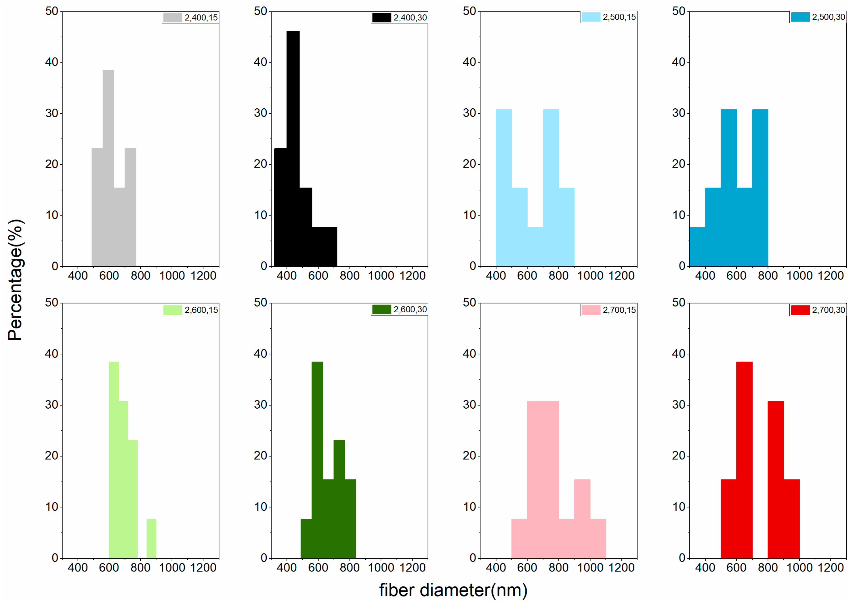
| Carbonization Temperature (°C) | Fiber Diameter (nm) | |||
|---|---|---|---|---|
| One-Step Activation | Two-Step Activation | |||
| 15 min | 30 min | 15 min | 30 min | |
| 400 | 792 a | 765 a | 622 a | 464 a |
| (5.67) | (18.09) | (13.94) | (22.56) | |
| 500 | 804 a | 794 a | 633 ab | 593 b |
| (9.93) | (13.61) | (26.11) | (22.63) | |
| 600 | 836 a | 807 a | 690 abc | 664 bc |
| (8.16) | (7.82) | (10.96) | (14.53) | |
| 700 | 841 a | 814 a | 760 bc | 746 c |
| (23.91) | (8.92) | (20.17) | (21.97) | |
| Treatment | Carbonization Temperature (°C) | Activation Time (min) | Surface Area (m2/g) | Pore Volume Proportion | Total Pore Volume (mL/g) | |
|---|---|---|---|---|---|---|
| Micro (%) | Meso (%) | |||||
| Carbonization | 700 | 112.15 | 12.37 | 87.63 | 0.023081 | |
| One-Step Activation | 400 | 15 | 64.10 | 9.50 | 90.50 | 0.028369 |
| 400 | 30 | 23.43 | 20.11 | 79.89 | 0.059510 | |
| 700 | 15 | 147.40 | 13.18 | 86.82 | 0.047106 | |
| 700 | 30 | 327.29 | 39.53 | 60.47 | 0.218590 | |
| Two-Step Activation | 400 | 15 | 98.43 | 35.04 | 64.96 | 0.136610 |
| 400 | 30 | 112.42 | 25.96 | 74.04 | 0.183690 | |
| 700 | 15 | 369.94 | 35.17 | 64.83 | 0.448810 | |
| 700 | 30 | 643.89 | 30.79 | 69.21 | 0.646930 | |
© 2018 by the authors. Licensee MDPI, Basel, Switzerland. This article is an open access article distributed under the terms and conditions of the Creative Commons Attribution (CC BY) license (http://creativecommons.org/licenses/by/4.0/).
Share and Cite
Chang, F.-C.; Yen, S.-H.; Wang, S.-H. Developing Lignosulfonate-Based Activated Carbon Fibers. Materials 2018, 11, 1877. https://doi.org/10.3390/ma11101877
Chang F-C, Yen S-H, Wang S-H. Developing Lignosulfonate-Based Activated Carbon Fibers. Materials. 2018; 11(10):1877. https://doi.org/10.3390/ma11101877
Chicago/Turabian StyleChang, Feng-Cheng, Shih-Hsuan Yen, and Szu-Han Wang. 2018. "Developing Lignosulfonate-Based Activated Carbon Fibers" Materials 11, no. 10: 1877. https://doi.org/10.3390/ma11101877
APA StyleChang, F.-C., Yen, S.-H., & Wang, S.-H. (2018). Developing Lignosulfonate-Based Activated Carbon Fibers. Materials, 11(10), 1877. https://doi.org/10.3390/ma11101877