Abstract
The object of this work was the deposition of a Ta-Hf-C thin film with a gold interlayer on stainless steel, via the physical vapor deposition (PVD) technique, in order to evaluate the properties of different systems subjected to micro-abrasive wear phenomena generated by alumina particles in Ringer's solution. The surface characterization was performed using a scanning electron microscope (SEM) and atomic force microscope (AFM). The crystallographic phases exhibited for each coating were obtained by X-ray diffraction (XRD). As a consequence of modifying the composition of Ta-Hf there was evidence of an improvement in the micro-abrasive wear resistance and, for each system, the wear constants that confirm the enhancement of the surface were calculated. Likewise, these surfaces can be bioactive, generating an alternative to improve the biological fixation of the implants, therefore, the coatings of TaC-HfC/Au contribute in the development of the new generation of orthopedic implants.
1. Introduction
In the field of orthopedic implants [1], biomaterials have become a major solution due to their properties for accomplishing specific biological functions [2,3]. However, depending on the types of materials, the reaction inside the human body may vary. In different studies, orthopedic implants which have metal-metal contact surfaces show an increase in ion release generated by the influence of the aqueous environment [4,5]. As a result, the highest level of metallic ions was measured in the blood and urine [6], in comparison with implants that have a contact surface of polymer-metal, ceramic-metal, or polymer-ceramic. Nevertheless, the systems with a contact surface of metal-metal generate a lower volume of periprosthetic inflammation in the tissue due to the lower liberation of particles that are produced with the wear with respect to other systems mentioned previously [7,8]. Therefore, the interest for studying the mechanical wear has increased since it became one of the main factors that cause implant failure or, in other cases, that can contaminate the environment that contains it in the long-term [9].
As a result of the requirement for improving the wear resistance, the PVD technique has allowed the deposition of thin films that modify the physical and chemical properties of the surface without modifying the mechanical properties of the substrate [10,11,12]. The use of tantalum as a biomaterial has good acceptance due to improvement in the corrosion resistance and wear resistance, and it also has good biocompatibility inside the human body [13,14]. Likewise, different studies have shown the significant applicability of tantalum as a coating because it exhibits similar mechanical properties as bone, such as high hardness and flexibility. Moreover, tantalum allows the regeneration of the biological material when it coats the implant [15,16].
Another material that is implemented in the biomaterials field is hafnium, as the addition of this material stimulates an improvement in wear resistance and surface integrity against deformation [17,18]. Furthermore, this material enhances the tensile strength and modulus of elasticity, decreasing the coefficient of friction [4,19]. Finally, as with tantalum, hafnium increases the corrosion resistance and has a good biocompatibility response [20].
The use of solid lubricants as a thin film has increased since traditional lubricants cannot reach some restrictions in the environments that require specific conditions, such as extreme temperatures [21], vacuum environments, or a high grade of purity as required inside the human body [22]. The solid lubricants are generated from “soft metals”, such as gold and silver [15], and through the PVD technique on different substrates [23,24]. Likewise, this type of lubricant is applied on various precision mechanisms, because its proper function depends on its pieces’ surface conditions. However, the characteristics of the selected lubricant may vary depending on the application and the conditions it will have to contend with when it is in service [25].
In the other hand, in thin films there exists a correlation between surface hardness and the coefficient of friction. At a higher hardness the coefficient of wear is lower, improving the response to wear phenomena [26,27]. To improve the surface hardness and reduce the presence and propagation of cracks, the process of carburization through the PVD technique has been highly applied as the addition of carbon results in a harder, more stable, and resistant film [28,29,30].
The aim of this work was to perform a deposition on 316LVM stainless steel with a coating of HfC/Au, TaC/Au, and mixtures of TaC-HfC in which the behavior of micro-abrasion wear in simulated biological conditions was evaluated. It was determined that the coatings improve against wear.
2. Materials and Methods
For the deposition of different coatings targets 50.8 mm diameter comprised of gold, tantalum, and hafnium with 99.95% purity and a carbon target with 99.999% purity were used in a confocal configuration at 0.4 Pa pressure in argon. For the deposition of different films the non-reactive magnetron sputtering technique in an AJA-ATC 1800 UHV equipment with a base pressure of 10−7 Pa was used.
Previously, the deposition of the films on substrates of 316LVM stainless steel were cleaned with ethanol and, subsequently, with plasma at a radio frequency (RF) with a power of 25 W in a pure argon environment at a pressure of 4 Pa for 10 minutes. Prior the deposition of the gold film, and to enhance the adhesion of the film to the substrate, was deposited a thin metallic layer of Ta-Hf with a thickness of approximately 20 nm between the substrate and the gold film by applying an RF power of 100 W to each Ta-Hf target. The gold films were obtained by applying a direct current (DC) power of 150 W to the gold target with a substrate rotation of 80 rpm for 20 minutes at room temperature, obtaining a thickness of 0.8 µm.
For the deposition of the different Ta-Hf-C films , the power applied to the targets was varied in the following way: 100-0 W (TaC), 70-30 W (70TaC 30HfC), 30-70 W (30TaC 70HfC), and 0-100 W (HfC), while the power of the carbon target remained at 380 W. Deposition of the different films was carried out with a target-substrate distance of 15 cm and at a temperature of 300 °C, with a negative RF voltage of 50 V.
The characterization of the crystalline phases was carried out on an X-ray diffractometer in a Bragg-Brentano configuration with a classic scintillation detector. The X-ray tube was made of copper with a Kα1 line of 1.540598 Å and Kα2 line of 1.544426 Å, with an incident ray radius of 240 mm. The voltage difference applied was 40 kV with an intensity of 30 mA, and the sweep interval was from 20 to 90°. The counting time designated for this test was stipulated at 2 s with a step size of 0.0400, for a total of 2125 points. Phase identification was performed in HighScore Plus software (Version 4.6a, Panalytical, Almelo, The Netherlands) with the ICSSD [31] and COD databases.
The micro-abrasion test was carried out in equipment that allows the simulation of the wear between two contact surfaces. The apparatus has a lever arm in which the sample is held and a fixed sphere between two coaxial axes. Through the movement of the counterweight, it is possible to regulate the load applied to the surface and the sphere, which is rotated by a DC motor with an encoder that guarantees control over the speed and number of cycles performed. Furthermore, a peristaltic pump adds a third body in the form of abrasive particles suspended in a solution to generate the micro-abrasive processes, as shown in Figure 1.
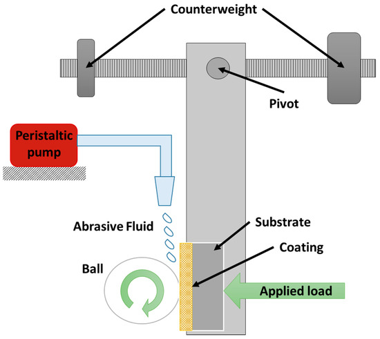
Figure 1.
Schematic of the micro-abrasion test apparatus which allow applying a normal load between the coated samples and the ball also shows how the alumina particles are added to the system.
With the aim to simulate biological conditions of a joint replacement by means of an ultra-high molecular weight polyethylene sphere and Ringer’s solution with alumina particles in suspension, the test parameters are shown in Table 1.

Table 1.
Test parameters.
For the estimation of the wear rate parameter, a model that relates the dimensions of the wear path performed on the surface of the sample with a wear constant was considered. According to the authors Gee et al. [32,33], the wear volume V is defined by:
where b is the average diameter of the scar and R is the radius of the sphere with which the test is performed. Relating Equation (1) with Archard's law of wear, Equation (2) is obtained, where K is the wear constant, S is the sliding distance, and N is the normal load applied:
The surface was observed by a JEOL NeoScope JMC-5000 scanning electron microscope operating under high vacuum at 10 kV. Superficial roughness was evaluated by measuring the arithmetic average of the roughness profile (Ra) through a NaioSurf atomic force microscope reference, and the measurement was carried out with an image size of 46.2 μm × 46.2 μm with a 1 s time/line, a resolution of 256 points/line, and a setpoint of 20 nN using the contact mode with a silicon tip coated with aluminum. The measurements were performed in two different zones: The first zone of analysis was obtained prior to each wear test to characterize the surface. In the second zone, the analysis was carried out in the central area generated by the sphere to identify the wear suffered by the coatings. All of the measurements were repeated three times. Using SPIP Image Metrology software, the images were analyzed to obtain the average roughness for each system before and after the micro-abrasion test [34].
3. Results and Discussion
3.1. XRD Characterization
In the interpretation of the crystalline phases of the coatings, the substrate was measured without any coating to identify the characteristics’ peaks that it presented, and subsequently identified the characterization of the different samples. Figure 2 shows the diffraction patterns obtained for each sample in which 316LVM stainless steel exhibited reflections at 43.7°, 50.52°, and 74.47°, attributed to the iron and chromium elements of the substrate and are also replicated in the measurement of the crystalline phases for most of the samples,. In films with a high content of hafnium, such as HfC/Au and 30TaC-70HfC/Au, the identification of reflections at 36.19°, 39.4°, and 69.37° were related with the Hf2Au1 phase with planes in (103), (110), and (213), with a tetragonal crystalline system. On the other hand, the samples with a high content of tantalum, such as TaC/Au and 70Tac-30HfC/Au, show a match at 35.01° and 40.75°, which are attributed to the phase of Ta4C3.04, with (111) and (020) planes in a cubic crystalline system.
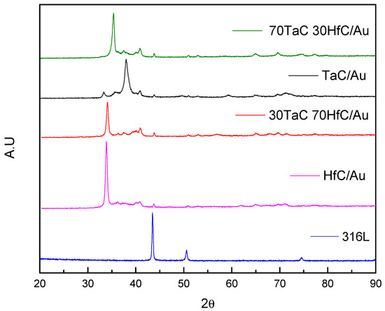
Figure 2.
Diffraction pattern of the substrate and the different samples of TaC/Au, HfC/Au, 30TaC/Au, and 70TaC-30HfC/Au studied using XRD.
In the samples with gold coatings, Figure 3 identified reflections at 38.068° and 82.05° with planes in (111) and (222) in a cubic crystalline system. Likewise, this sample showed a high crystallinity because the count obtained for this sample was much higher in comparison to the other samples. Moreover, gold phases were identified in the samples of TaC/Au and HfC/Au at an angle of 38.068°, which is more evident for the sample of TaC/Au.
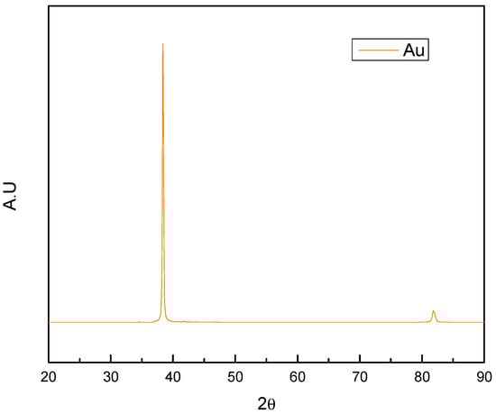
Figure 3.
Gold coating pattern studied using XRD.
3.2. Wear Estimation
Through the scanning electron microscope technique the length of the scar generated by the wear process was measured. The measurement was carried out parallel and perpendicular to the direction of rotation of the sphere, as shown in Figure 4. These lengths were averaged to obtain an estimated diameter of the scar for each sample, as shown in Table 2.
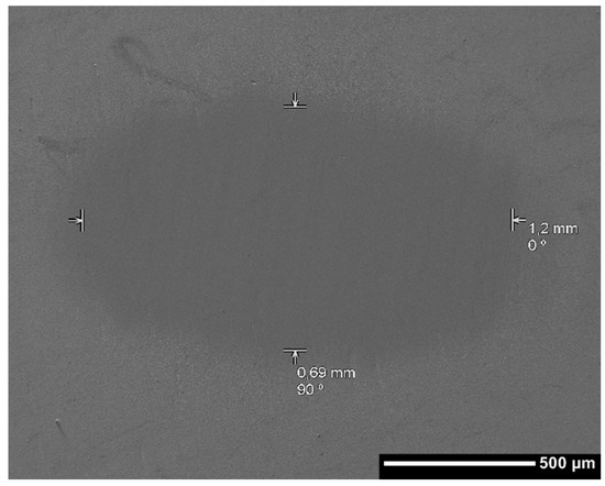
Figure 4.
Micrograph of the wear scar length measure through SEM technique.
Table 2.
Measurement of length.
Taking into account the average lengths, all of the tests were carried out with a normal force of 3 N and a sliding distance of 78.53 m, as used in Equations (1) and (2), to obtain the wear volume and the wear constants as shown in Figure 5.
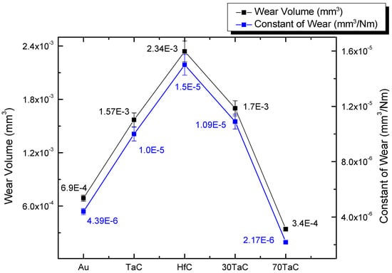
Figure 5.
Contrast between the wear volume and constant of wear for each coated system.
The coating of 70Tac 30HfC/Au shows the lowest constant wear value, followed by the gold sample, indicating a superior behavior against the micro-abrasion wear compared with the other systems. On the other hand, the coatings’ performances of TaC, HfC, and 30TaC 70HfC were similar, where the highest value was exhibited by the HfC sample. Nevertheless, all of the coatings showed values in their constants lower than 10−4, which indicated great performance since the wear was moderate [35].
3.3. Morphological Analysis
After the test was carried out measurements on the wear scar through SEM and AFM techniques were conducted to morphologically characterize the surface.
3.3.1. SEM
In Figure 6, the micrographs of the evaluated surface were observed with a magnification of 1000× and only the two most relevant micrographs are shown since a significant change is not evident in comparison with the other systems. From the micrographs it can be seen that the coatings protect the substrate from wear phenomena, which can be identified by the total removal of the coating until access to the substrate is achieved.

Figure 6.
Micrograph of the most affected area by micro-abrasion tests studied by SEM technique. (a) Au, and (b) TaC/Au.
In Figure 6b good performance against wear is observed, since the surface damage was minimal. Nevertheless, the coating of gold in Figure 6a shows the start of the mechanism of wear by micro-abrasion, and the micrograph reveals small grooves defined in the direction of the movement of the alumina particles, which is characteristic of the grooved wear regime.
3.3.2. AFM
In the micrographs obtained by AFM, Figure 7 shows the surface characterization of the different samples. All of the surfaces exhibited a variation in the roughness, as shown in Figure 8, that was induced by the effect of the sphere with the addition of the alumina particles. After the micro-abrasion test three types of surface variation was observed, with the largest change of the roughness value shown by the sample of HfC/Au (Figure 8), which was related to the morphological change associated with the ridge degradation, interpreted for this case of study as severe variation.
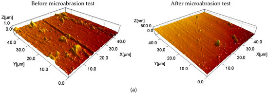
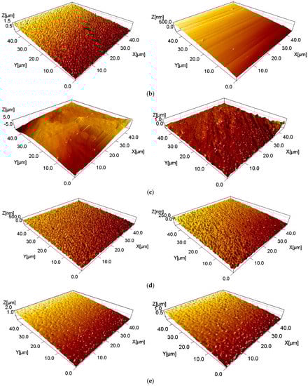
Figure 7.
Surface characterization of each sample using AFM technique before and after micro-abrasion test (a) Au, (b) TaC/Au, (c) HfC/Au, (d) 30TaC-70HfC/Au, and (e) 70TaC-30 HfC/Au.
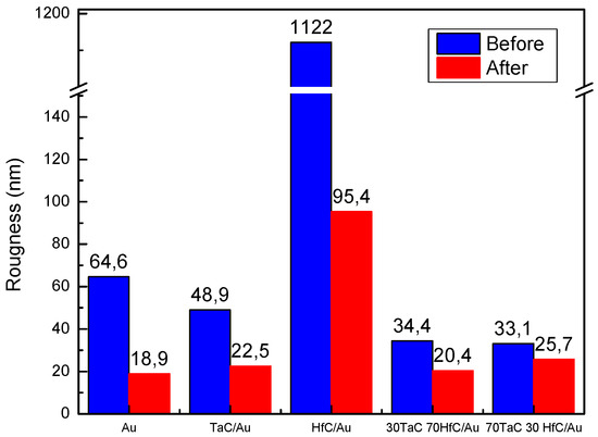
Figure 8.
Quantitative variation of the roughness measurements before and after micro-abrasion test using AFM technique and analyzed by SPIP Image Metrology software.
On the other hand, samples of TaC/Au and gold showed a superficial variation considered average as a consequence of a morphological change that eliminated material and homogenized the surfaces. Finally, samples with a combination of TaC-HfC exhibited a slight morphologic change related with the other systems in addition to showing a lower roughness value.
4. Conclusions
In the characterization of the crystalline phases it can be concluded that the gold coating had a major crystalline orientation compared with the other coatings since the gold thin film obtained by PVD showed a crystalline cubic structure, reflected in the counts obtained for this sample.
Regardless of the varying deposition parameters, the crystalline phase of Hf2Au1 tends to replicate in both the pure HfC/Au samples, as well the 30TaC-70HfC/Au samples, and also the Ta4C3.04 phase was identified for the coatings of TaC/Au and 70TaC-30HfC/Au.
All of the systems evaluated in this study had a good behavior against the phenomenon of micro-abrasion wear in the presence of Ringer’s solution, which is evidenced by the low values of the wear constants. Furthermore, although the HfC coating presented the highest value in terms of the wear constant, it shows advantages when it is in service since its roughness decreases significantly, generating a lower friction.
Although the Au film showed signs of grooved debris by micro-abrasive processes, it was also one of the systems with the best behavior, due to exhibiting the second-lowest wear constant value. On the other hand, after the system of HfC/Au, the gold system showed a greater decrease in its roughness and had the lowest value related to the others coatings.
Moreover, the coatings obtained via PVD allows generating a thin film that functions as a protective barrier against wear phenomena which is one of the main causes of failure of an implant due to deterioration and development of surface wear and cracks propagation. This degradation can extend through all the surface of the material and is important to avoid this kind of circumstance because in extreme cases can affect the structural integrity of the implant leading to the need of remove the implant.
Acknowledgments
This research was supported by “Vicerrectoría de investigaciones de la Universidad Militar Nueva Granada” under contract ING-2374–2017. Mercy Sandoval acknowledge to Young Researchers and Innovators of COLCIENCIAS, under contract 621-2015.
Author Contributions
Luis Yate performed the deposition of the thin films, and Willian Aperador worked in the wear experiments and the respective analysis. Pablo Guzmán performed measurements in SEM and DRX and performed the interpretation of the data. Jose Caballero and Mercy Sandoval performed the measurements in AFM and the interpretation of the data. All of the authors carried out the writing of the manuscript.
Conflicts of Interest
The authors declare no conflict of interest.
References
- Wang, S.P.; Xu, J. TiZrNbTaMo high-entropy alloy designed for orthopedic implants: As-cast microstructure and mechanical properties. Mater. Sci. Eng. C 2017, 73, 80–89. [Google Scholar] [CrossRef] [PubMed]
- Ibrahim, M.Z.; Sarhan, A.A.D.; Yusuf, F.; Hamdi, M. Biomedical materials and techniques to improve the tribological, mechanical and biomedical properties of orthopedic implants—A review article. J. Alloys Compd. 2017, 714, 636–667. [Google Scholar] [CrossRef]
- Niinomi, M.; Nakai, M.; Hieda, J. Development of new metallic alloys for biomedical applications. Acta Biomater. 2012, 8, 3888–3903. [Google Scholar] [CrossRef] [PubMed]
- Mora, M.; Vera, E.; Aperador, W. Tribo-electrochemical characterization of hafnium multilayer systems deposited on nitride/vanadium nitride AISI 4140 steel. J. Phys. Conf. Ser. 2016, 687, 12032. [Google Scholar] [CrossRef]
- Tolan, N.V.; Sierra, R.J.; Moyer, T.P. Evidence against implant-derived cobalt toxicity: Case report and retrospective study of serum cobalt concentrations in an orthopedic implant population. Clin. Biochem. 2015, 48, 130–134. [Google Scholar] [CrossRef] [PubMed]
- Spriano, S.; Vernè, E.; Faga, M.G.; Bugliosi, S.; Maina, G. Surface treatment on an implant cobalt alloy for high biocompatibility and wear resistance. Wear 2005, 259, 919–925. [Google Scholar] [CrossRef]
- Scholes, S.C.; Unsworth, A.; Hall, R.M.; Scott, R. The effects of material combination and lubricant on the friction of total hip prostheses. Wear 2000, 241, 209–213. [Google Scholar] [CrossRef]
- Kunčická, L.; Kocich, R.; Lowe, T.C. Advances in metals and alloys for joint replacement. Prog. Mater. Sci. 2017, 88, 232–280. [Google Scholar] [CrossRef]
- Longhofer, L.K.; Chong, A.; Strong, N.M.; Wooley, P.H.; Yang, S.-Y. Specific material effects of wear-particle-induced inflammation and osteolysis at the bone—Implant interface: A rat model. J. Orthop. Transl. 2017, 8, 5–11. [Google Scholar] [CrossRef]
- Kaliaraj, G.S.; Bavanilathamuthiah, M.; Kirubaharan, K.; Ramachandran, D.; Dharini, T.; Viswanathan, K.; Vishwakarma, V. Bio-inspired YSZ coated titanium by EB-PVD for biomedical applications. Surf. Coat. Technol. 2016, 307, 227–235. [Google Scholar] [CrossRef]
- Marin, E.; Offoiach, R.; Regis, M.; Fusi, S.; Lanzutti, A.; Fedrizzi, L. Diffusive thermal treatments combined with PVD coatings for tribological protection of titanium alloys. Mater. Des. 2016, 89, 314–322. [Google Scholar] [CrossRef]
- Naghibi, S.A.; Raeissi, K.; Fathi, M.H. Corrosion and tribocorrosion behavior of Ti/TiN PVD coating on 316L stainless steel substrate in Ringer’s solution. Mater. Chem. Phys. 2014, 148, 614–623. [Google Scholar] [CrossRef]
- Rahmati, B.; Zalnezhad, E.; Sarhan, A.A.D.; Kamiab, Z.; Tabrizi, B.N.; Abas, W.A.B.W. Enhancing the adhesion strength of tantalum oxide ceramic thin film coating on biomedical Ti-6Al-4V alloy by thermal surface treatment. Ceram. Int. 2015, 41, 13055–13063. [Google Scholar] [CrossRef]
- Guzmán, P.; Aperador, W.; Yate, L. Enhancement of the Pitting Corrosion Resistance of AISI 316LVM Steel with Ta-Hf-C/Au Bilayers for Biomedical Applications. J. Nanomater. 2017. [Google Scholar] [CrossRef]
- Wauthle, R.; van der Stok, J.; Yavari, S.A.; van Humbeeck, J.; Kruth, J.-P.; Zadpoor, A.A.; Weinans, H.; Mulier, M.; Schrooten, J. Additively manufactured porous tantalum implants. Acta Biomater. 2015, 14, 217–225. [Google Scholar] [CrossRef] [PubMed]
- Ching, H.A.; Choudhury, D.; Nine, M.J.; Azuan, N.; Osman, A. Effects of surface coating on reducing friction and wear of orthopaedic implants. Sci. Technol. Adv. Mater. 2014, 15, 14402–14421. [Google Scholar] [CrossRef] [PubMed]
- Kim, H.; Lee, H.B.R.; Maeng, W.J. Applications of atomic layer deposition to nanofabrication and emerging nanodevices. Thin Solid Films 2009, 517, 2563–2580. [Google Scholar] [CrossRef]
- Zhao, T.; Li, Y.; Liu, Y.; Zhao, X. Nano-hardness, wear resistance and pseudoelasticity of hafnium implanted NiTi shape memory alloy. J. Mech. Behav. Biomed. Mater. 2012, 13, 174–184. [Google Scholar] [CrossRef] [PubMed]
- Hon, Y.H.; Wang, J.Y.; Pan, Y.N. Influence of hafnium content on mechanical behaviors of Ti-40Nb-xHf alloys. Mater. Lett. 2004. [Google Scholar] [CrossRef]
- Jin, W.; Wu, G.; Gao, A.; Feng, H.; Peng, X.; Chu, P.K. Hafnium-implanted WE43 magnesium alloy for enhanced corrosion protection and biocompatibility. Surf. Coat. Technol. 2016, 306, 11–15. [Google Scholar] [CrossRef]
- Shi, X.; Zhai, W.; Wang, M.; Xu, Z.; Yao, J.; Song, S.; Wang, Y. Tribological behaviors of NiAl based self-lubricating composites containing different solid lubricants at elevated temperatures. Wear 2014, 310, 1–11. [Google Scholar] [CrossRef]
- Zhao, G.H.; Aune, R.E.; Espallargas, N. Tribocorrosion studies of metallic biomaterials: The effect of plasma nitriding and DLC surface modifications. J. Mech. Behav. Biomed. Mater. 2016, 63, 100–114. [Google Scholar] [CrossRef] [PubMed]
- Miyake, S.; Shindo, T.; Miyake, M. Deposition and Tribology of Electroconductive and Wear-Resistant Nanocomposite Solid Lubricant Films Composed of Carbon and Silver or Gold. Tribol. Lett. 2016, 61, 1–9. [Google Scholar] [CrossRef]
- Hilton, M.R.; Fleischauer, P.D. Applications of solid lubricant films in spacecraft. Surf. Coat. Technol. 1992, 54, 435–441. [Google Scholar] [CrossRef]
- Spalvins, T. A review of recent advances in solid film lubrication. J. Vac. Sci. Technol. 1987, 5, 212–219. [Google Scholar] [CrossRef]
- Shi, L.; Guo, Z.G.; Liu, W.M. The recent progress of tribological biomaterials. Biosurf. Biotribol. 2015, 1, 81–97. [Google Scholar]
- Buckley, H. The X-Ray Photoelectron Spectroscopy Depth Profiling And Tribological Characterization Plated Gold On Various Metals * An investigation was conducted to examine, by X-ray photoelectron spec- troscopy analysis and depth profiling, the atomic nature of su. Thin Soild Films 1983, 108, 199–207. [Google Scholar]
- Chetan; Behera, B.C.; Ghosh, S.; Rao, P.V. Wear behavior of PVD TiN coated carbide inserts during machining of Nimonic 90 and Ti6Al4V superalloys under dry and MQL conditions. Ceram. Int. 2016, 42, 14873–14885. [Google Scholar]
- Veronesi, F.; Giavaresi, G.; Fini, M.; Longo, G.; Ioannidu, C.A.; d’Abusco, A.S.; Superti, F.; Panzini, G.; Misiano, C.; Palattella, A.; et al. Osseointegration is improved by coating titanium implants with a nanostructured thin film with titanium carbide and titanium oxides clustered around graphitic carbon. Mater. Sci. Eng. 2017, 70, 264–271. [Google Scholar] [CrossRef] [PubMed]
- Zhang, W.; Du, Y.; Peng, Y. Effect of TaC and NbC addition on the microstructure and hardness in graded cemented carbides: Simulations and experiments. Ceram. Int. 2015, 42, 428–435. [Google Scholar] [CrossRef]
- Degen, T.; Sadki, M.; Bron, E.; König, U.; Nénert, G. The HighScore suite. Powder Diffr. 2014, 29, S13–S18. [Google Scholar] [CrossRef]
- Gee, M.G.; Gant, A.; Hutchings, I.M.; Bethke, R.; Schiffman, K.; Acker, K.V.; Poulat, S.; Gachon, Y.; von Stebut, J. Ball Cratering or Micro-Abrasion Wear Testing of Coatings: Good Practice Guide 057; British Library: Teddington, UK, 2002; p. 58. [Google Scholar]
- Gee, M.G.; Gant, A.; Hutchings, I.; Bethke, R.; Schiffman, K.; van Acker, K.; Poulat, S.; Gachon, Y.; von Stebut, J. Progress towards standardisation of ball cratering. Wear 2003, 255, 1–13. [Google Scholar] [CrossRef]
- Zhang, X.; Järn, M.; Peltonen, J.; Pore, V.; Vuorinen, T.; Levänen, E.; Mäntylä, T. Analysis of roughness parameters to specify superhydrophobic antireflective boehmite films made by the sol-gel process. J. Eur. Ceram. Soc. 2008, 28, 2177–2181. [Google Scholar] [CrossRef]
- Zivic, F.; Babic, M.; Grujovic, N.; Mitrovic, S.; Adamovic, D. Influence of loose PMMA bone cement particles on the corrosion assisted wear of the orthopedic AISI 316LVM stainless steel during reciprocating sliding. Wear 2013, 300, 65–77. [Google Scholar] [CrossRef]
© 2017 by the authors. Licensee MDPI, Basel, Switzerland. This article is an open access article distributed under the terms and conditions of the Creative Commons Attribution (CC BY) license (http://creativecommons.org/licenses/by/4.0/).