
A Shell Model for Free Vibration Analysis of Carbon Nanoscroll


Abstract
:1. Introduction
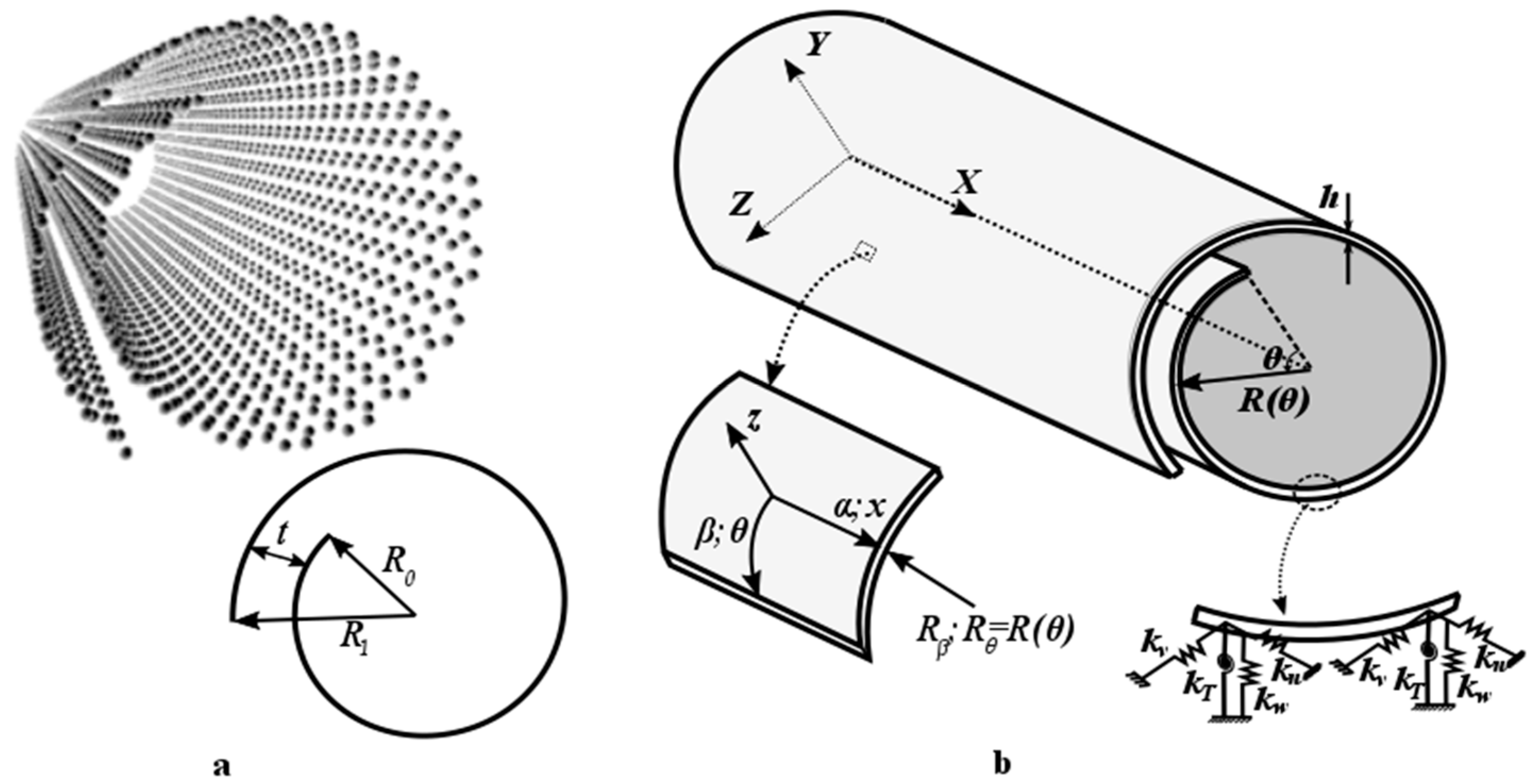
2. Modeling
2.1. Equivalent Parameters
2.2. Continuum Shell Theory
2.3. Van der Waals Interactions
2.4. Boundary Conditions
2.5. Solution Method
3. Results and Discussion
3.1. Verification of the Model
3.1.1. Convergence Study and Comparison between CNS and MWCNT
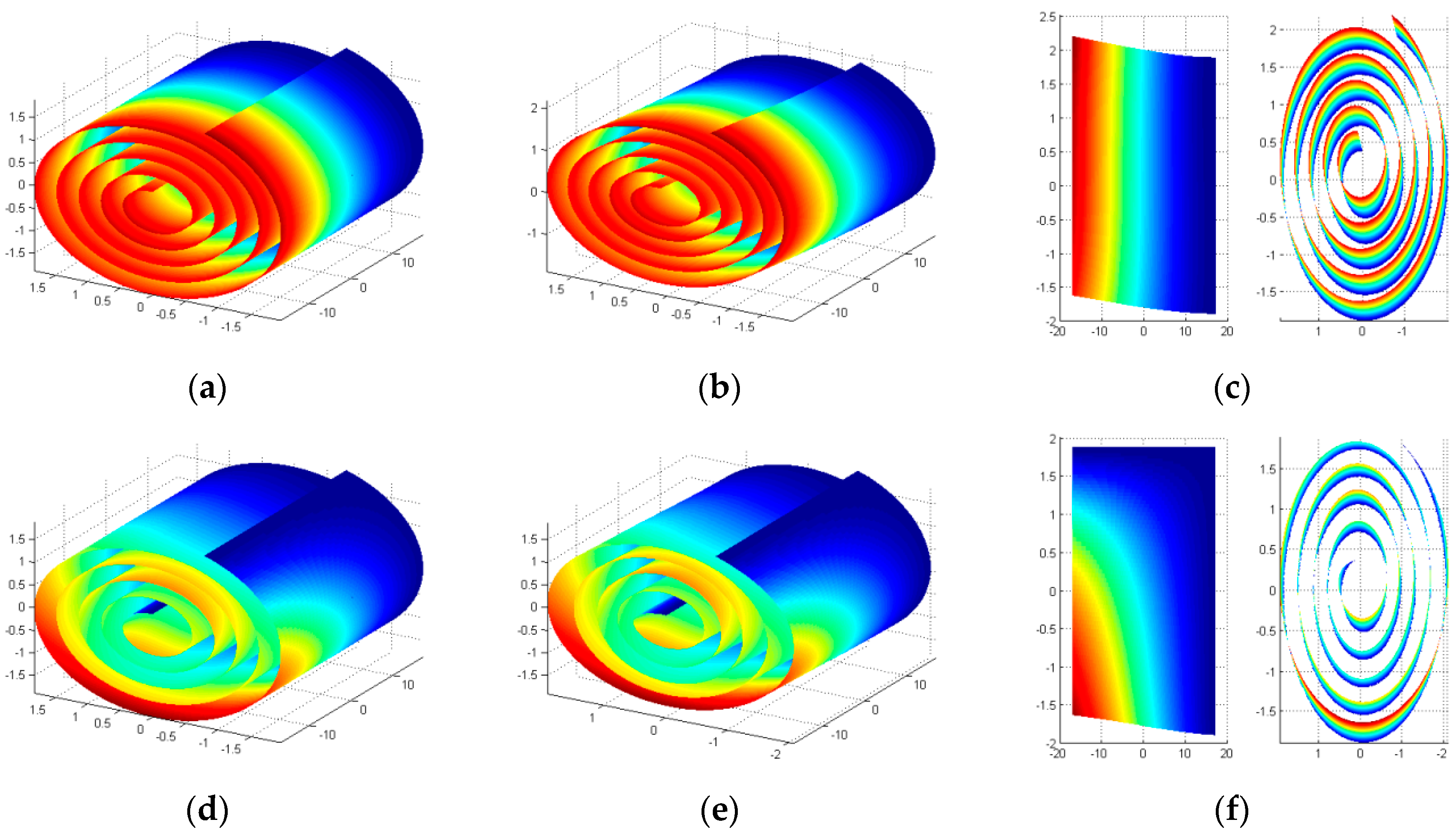
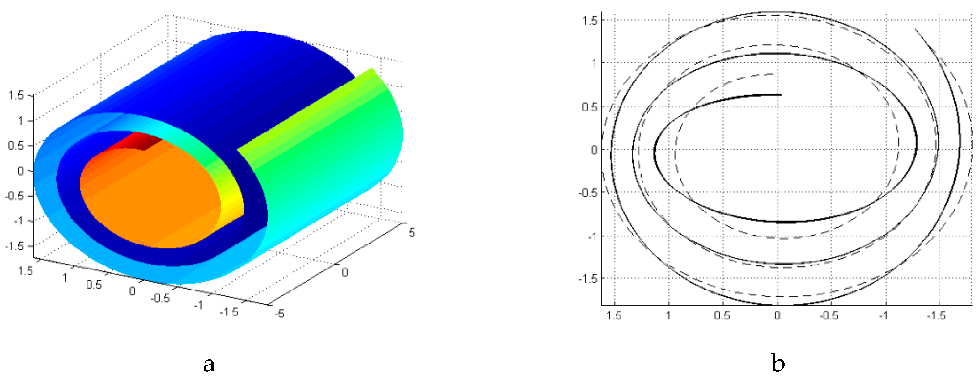
3.1.2. The Breathing like Mode
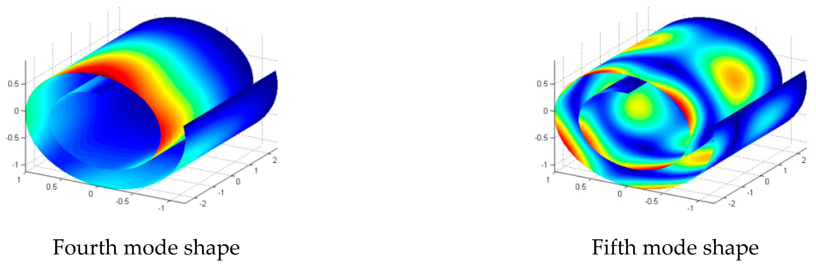
3.2. Vibration of a CNS with Different Boundary Conditions
3.3. Vibration of a CNS with Different Lengths
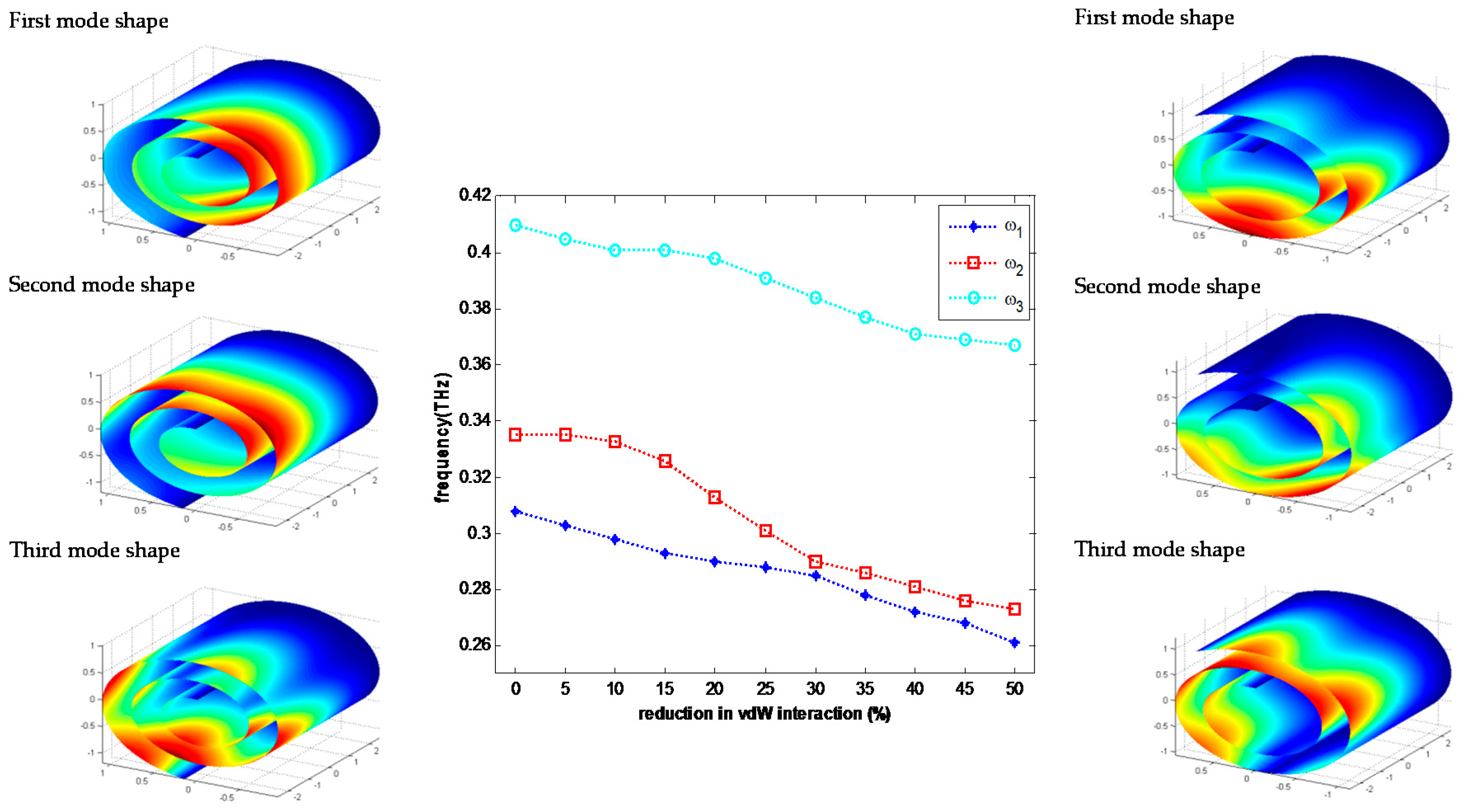
3.4. Effect of Van der Waals Interactions on the Vibration of a CNS
4. Conclusions
Acknowledgments
Author Contributions
Conflicts of Interest
Appendix A
References
- Bacon, R. Growth, structure, and properties of graphite whiskers. J. Appl. Phys. 1960, 31, 283–290. [Google Scholar] [CrossRef]
- Viculis, L.M.; Mack, J.J.; Kaner, R.B. A chemical route to carbon nanoscrolls. Science 2003, 299, 1361. [Google Scholar] [CrossRef] [PubMed]
- Roy, D.; Angeles-Tactay, E.; Brown, R.; Spencer, S.; Fry, T.; Dunton, T.; Young, T.; Milton, M. Synthesis and raman spectroscopic characterisation of carbon nanoscrolls. Chem. Phys. Lett. 2008, 465, 254–257. [Google Scholar] [CrossRef]
- Savoskin, M.V.; Mochalin, V.N.; Yaroshenko, A.P.; Lazareva, N.I.; Konstantinova, T.E.; Barsukov, I.V.; Prokofiev, I.G. Carbon nanoscrolls produced from acceptor-type graphite intercalation compounds. Carbon 2007, 45, 2797–2800. [Google Scholar] [CrossRef]
- Xie, X.; Ju, L.; Feng, X.; Sun, Y.; Zhou, R.; Liu, K.; Fan, S.; Li, Q.; Jiang, K. Controlled fabrication of high-quality carbon nanoscrolls from monolayer graphene. Nano Lett. 2009, 9, 2565–2570. [Google Scholar] [CrossRef] [PubMed]
- Zheng, J.; Liu, H.; Wu, B.; Guo, Y.; Wu, T.; Yu, G.; Liu, Y.; Zhu, D. Production of high-quality carbon nanoscrolls with microwave spark assistance in liquid nitrogen. Adv. Mater. 2011, 23, 2460–2463. [Google Scholar] [CrossRef] [PubMed]
- Karimi, H.; Ahmadi, M.T.; Khosrowabadi, E.; Rahmani, R.; Saeidimanesh, M.; Ismail, R.; Naghib, S.D.; Akbari, E. Analytical prediction of liquid-gated graphene nanoscroll biosensor performance. RSC Adv. 2014, 4, 16153–16162. [Google Scholar] [CrossRef]
- Shi, X.; Cheng, Y.; Pugno, N.M.; Gao, H. Tunable water channels with carbon nanoscrolls. Small 2010, 6, 739–744. [Google Scholar] [CrossRef] [PubMed]
- Zeng, F.; Kuang, Y.; Liu, G.; Liu, R.; Huang, Z.; Fu, C.; Zhou, H. Supercapacitors based on high-quality graphene scrolls. Nanoscale 2012, 4, 3997–4001. [Google Scholar] [CrossRef] [PubMed]
- Huang, Y.; Li, T. Molecular mass transportation via carbon nanoscrolls. J. Appl. Mech. 2013, 80, 040903. [Google Scholar] [CrossRef]
- Mpourmpakis, G.; Tylianakis, E.; Froudakis, G.E. Carbon nanoscrolls: A promising material for hydrogen storage. Nano Lett. 2007, 7, 1893–1897. [Google Scholar] [CrossRef] [PubMed]
- Coluci, V.; Braga, S.; Baughman, R.; Galvao, D. Prediction of the hydrogen storage capacity of carbon nanoscrolls. Phys. Rev. B 2007, 75, 125404. [Google Scholar] [CrossRef]
- Shi, X.; Pugno, N.M.; Gao, H. Tunable core size of carbon nanoscrolls. J. Comput. Theor. Nanosci. 2010, 7, 517–521. [Google Scholar] [CrossRef]
- Shi, X.; Pugno, N.M.; Gao, H. Constitutive behavior of pressurized carbon nanoscrolls. Int. J. Fract. 2011, 171, 163–168. [Google Scholar] [CrossRef]
- Schaper, A.K.; Wang, M.S.; Xu, Z.; Bando, Y.; Golberg, D. Comparative studies on the electrical and mechanical behavior of catalytically grown multiwalled carbon nanotubes and scrolled graphene. Nano Lett. 2011, 11, 3295–3300. [Google Scholar] [CrossRef] [PubMed]
- Zaeri, M.M.; Ziaei-Rad, S. Elastic properties of carbon nanoscrolls. RSC Adv. 2014, 4, 22995–23001. [Google Scholar] [CrossRef]
- Shi, X.; Yin, Q.; Pugno, N.M.; Gao, H. Tunable mechanical behavior of carbon nanoscroll crystals under uniaxial lateral compression. J. Appl. Mech. 2014, 81, 021014. [Google Scholar] [CrossRef]
- Zhang, Z.; Huang, Y.; Li, T. Buckling instability of carbon nanoscrolls. J. Appl. Phys. 2012, 112, 063515. [Google Scholar] [CrossRef]
- Shi, X.; Cheng, Y.; Pugno, N.M.; Gao, H. A translational nanoactuator based on carbon nanoscrolls on substrates. Appl. Phys. Lett. 2010, 96, 053115. [Google Scholar] [CrossRef]
- Shi, X.; Pugno, N.M.; Cheng, Y.; Gao, H. Gigahertz breathing oscillators based on carbon nanoscrolls. Appl. Phys. Lett. 2009, 95, 163113. [Google Scholar] [CrossRef]
- Cheng, Y.; Shi, X.; Pugno, N.M.; Gao, H. Substrate-supported carbon nanoscroll oscillator. Phys. E Low Dimens. Syst. Nanostruct. 2012, 44, 955–959. [Google Scholar] [CrossRef]
- Pishkenari, H.N.; Ghanbari, P.G. Vibrational properties of c 60: A comparison among different inter-atomic potentials. Comput. Mater. Sci. 2016, 122, 38–45. [Google Scholar] [CrossRef]
- Lee, J.; Lee, B. Modal analysis of carbon nanotubes and nanocones using fem. Comput. Mater. Sci. 2012, 51, 30–42. [Google Scholar] [CrossRef]
- Yakobson, B.I.; Brabec, C.; Bernholc, J. Nanomechanics of carbon tubes: Instabilities beyond linear response. Phys. Rev. Lett. 1996, 76, 2511. [Google Scholar] [CrossRef] [PubMed]
- Sánchez-Portal, D.; Artacho, E.; Soler, J.M.; Rubio, A.; Ordejón, P. Ab initio structural, elastic, and vibrational properties of carbon nanotubes. Phys. Rev. B 1999, 59, 12678. [Google Scholar] [CrossRef]
- Mahan, G. Oscillations of a thin hollow cylinder: Carbon nanotubes. Phys. Rev. B 2002, 65, 235402. [Google Scholar] [CrossRef]
- Silvestre, N. Length dependence of critical measures in single-walled carbon nanotubes. Int. J. Solids Struct. 2008, 45, 4902–4920. [Google Scholar] [CrossRef]
- Silvestre, N.; Wang, C.; Zhang, Y.; Xiang, Y. Sanders shell model for buckling of single-walled carbon nanotubes with small aspect ratio. Comp. Struct. 2011, 93, 1683–1691. [Google Scholar] [CrossRef]
- Peng, J.; Wu, J.; Hwang, K.; Song, J.; Huang, Y. Can a single-wall carbon nanotube be modeled as a thin shell? J. Mech. Phys. Solids 2008, 56, 2213–2224. [Google Scholar] [CrossRef]
- Wang, C.; Ru, C.; Mioduchowski, A. Applicability and limitations of simplified elastic shell equations for carbon nanotubes. J. Appl. Mech. 2004, 71, 622–631. [Google Scholar] [CrossRef]
- Silvestre, N. On the accuracy of shell models for torsional buckling of carbon nanotubes. Eur. J. Mech. A/Solids 2012, 32, 103–108. [Google Scholar] [CrossRef]
- Ru, C. Effective bending stiffness of carbon nanotubes. Phys. Rev. B 2000, 62, 9973. [Google Scholar] [CrossRef]
- Vodenitcharova, T.; Zhang, L. Effective wall thickness of a single-walled carbon nanotube. Phys. Rev. B 2003, 68, 165401. [Google Scholar] [CrossRef]
- Odegard, G.M.; Gates, T.S.; Nicholson, L.M.; Wise, K.E. Equivalent-continuum modeling of nano-structured materials. Comp. Sci. Technol. 2002, 62, 1869–1880. [Google Scholar] [CrossRef]
- Zhang, P.; Huang, Y.; Geubelle, P.; Klein, P.; Hwang, K. The elastic modulus of single-wall carbon nanotubes: A continuum analysis incorporating interatomic potentials. Int. J. Solids Struct. 2002, 39, 3893–3906. [Google Scholar] [CrossRef]
- Chang, T. A molecular based anisotropic shell model for single-walled carbon nanotubes. J. Mech. Phys. Solids 2010, 58, 1422–1433. [Google Scholar] [CrossRef]
- Kiani, K. A meshless approach for free transverse vibration of embedded single-walled nanotubes with arbitrary boundary conditions accounting for nonlocal effect. Int. J. Mech. Sci. 2010, 52, 1343–1356. [Google Scholar] [CrossRef]
- Ru, C. Column buckling of multiwalled carbon nanotubes with interlayer radial displacements. Phys. Rev. B 2000, 62, 16962. [Google Scholar] [CrossRef]
- Saito, R.; Matsuo, R.; Kimura, T.; Dresselhaus, G.; Dresselhaus, M. Anomalous potential barrier of double-wall carbon nanotube. Chem. Phys. Lett. 2001, 348, 187–193. [Google Scholar] [CrossRef]
- Sudak, L. Column buckling of multiwalled carbon nanotubes using nonlocal continuum mechanics. J. Appl. Phys. 2003, 94, 7281–7287. [Google Scholar] [CrossRef]
- Zhang, Y.; Liu, G.; Xie, X. Free transverse vibrations of double-walled carbon nanotubes using a theory of nonlocal elasticity. Phys. Rev. B 2005, 71, 195404. [Google Scholar] [CrossRef]
- Strozzi, M.; Manevitch, L.I.; Pellicano, F.; Smirnov, V.V.; Shepelev, D.S. Low-frequency linear vibrations of single-walled carbon nanotubes: Analytical and numerical models. J. Sound Vib. 2014, 333, 2936–2957. [Google Scholar] [CrossRef]
- Arghavan, S.; Singh, A. On the vibrations of single-walled carbon nanotubes. J. Sound Vib. 2011, 330, 3102–3122. [Google Scholar] [CrossRef]
- Natsuki, T.; Ni, Q.-Q.; Endo, M. Analysis of the vibration characteristics of double-walled carbon nanotubes. Carbon 2008, 46, 1570–1573. [Google Scholar] [CrossRef]
- Wang, C.; Ru, C.; Mioduchowski, A. Free vibration of multiwall carbon nanotubes. J. Appl. Phys. 2005, 97, 114323. [Google Scholar] [CrossRef]
- Xu, K.-Y.; Aifantis, E.C.; Yan, Y.-H. Vibrations of double-walled carbon nanotubes with different boundary conditions between inner and outer tubes. J. Appl. Phys. 2008, 75, 021013. [Google Scholar] [CrossRef]
- Chowdhury, R.; Wang, C.; Adhikari, S. Low frequency vibration of multiwall carbon nanotubes with heterogeneous boundaries. J. Phys. D Appl. Phys. 2010, 43, 085405. [Google Scholar] [CrossRef]
- Liu, R.; Wang, L. Coupling between flexural modes in free vibration of single-walled carbon nanotubes. AIP Adv. 2015, 5, 127110. [Google Scholar] [CrossRef]
- Eshraghi, I.; Jalali, S.K.; Pugno, N.M. Imperfection sensitivity of nonlinear vibration of curved single-walled carbon nanotubes based on nonlocal timoshenko beam theory. Materials 2016, 9, 786. [Google Scholar] [CrossRef]
- Smirnov, V.; Manevitch, L.; Strozzi, M.; Pellicano, F. Nonlinear optical vibrations of single-walled carbon nanotubes. 1. Energy exchange and localization of low-frequency oscillations. Phys. D Nonlinear Phenom. 2016, 325, 113–125. [Google Scholar] [CrossRef]
- Strozzi, M.; Smirnov, V.V.; Manevitch, L.I.; Milani, M.; Pellicano, F. Nonlinear vibrations and energy exchange of single-walled carbon nanotubes. Circumferential flexural modes. J. Sound Vib. 2016, 381, 156–178. [Google Scholar] [CrossRef]
- Liew, K.M.; Wang, Q. Analysis of wave propagation in carbon nanotubes via elastic shell theories. Int. J. Eng. Sci. 2007, 45, 227–241. [Google Scholar] [CrossRef]
- Wang, L.; Hu, H. Flexural wave propagation in single-walled carbon nanotubes. Phys. Rev. B 2005, 71, 195412. [Google Scholar] [CrossRef]
- Wu, B.; Guo, X.; Ru, C. Reduced vibrational frequencies of multiwall carbon nanotubes due to interlayer degrees of freedom. Eur. J. Mech. A/Solids 2014, 47, 206–210. [Google Scholar] [CrossRef]


| Boundary Condition | CFFF | CFCC | |||||||
|---|---|---|---|---|---|---|---|---|---|
| M × N | 20 × 20 | 25 × 25 | 27 × 27 | 20 × 20 | 22 × 22 | 25 × 25 | 27 × 27 | 28 × 28 | |
| Mode Shape | 1 | 17 | 10 | 10 | 83 | 79 | 77 | 77 | 77 |
| 2 | 27 | 11 | 11 | 112 | 112 | 111 | 111 | 111 | |
| 3 | 48 | 48 | 48 | 130 | 127 | 123 | 121 | 121 | |
| 4 | 60 | 58 | 58 | 138 | 134 | 127 | 126 | 126 | |
| 5 | 66 | 62 | 62 | 163 | 160 | 150 | 147 | 147 | |
| 6 | 70 | 70 | 70 | 201 | 200 | 197 | 196 | 196 | |
| 7 | 147 | 146 | 146 | 213 | 211 | 208 | 207 | 207 | |
| 8 | 147 | 147 | 147 | 225 | 223 | 217 | 215 | 215 | |
| 9 | 151 | 151 | 151 | 244 | 243 | 241 | 240 | 240 | |
| 10 | 156 | 154 | 154 | 275 | 275 | 274 | 274 | 274 | |
| Mode Shape | Boundary Condition | ||||
|---|---|---|---|---|---|
| CCCC | SSDD | CCFF | DDDD | FCSS | |
| 1 | 0.59 | 0.52 | 0.44 | 0.36 | 0.27 |
| 2 | 0.60 | 0.56 | 0.49 | 0.43 | 0.33 |
| 3 | 0.72 | 0.68 | 0.62 | 0.56 | 0.36 |
| 4 | 0.73 | 0.71 | 0.65 | 0.63 | 0.40 |
| 5 | 0.88 | 0.80 | 0.65 | 0.65 | 0.60 |
© 2017 by the authors. Licensee MDPI, Basel, Switzerland. This article is an open access article distributed under the terms and conditions of the Creative Commons Attribution (CC BY) license (http://creativecommons.org/licenses/by/4.0/).
Share and Cite
Taraghi Osguei, A.; Ahmadian, M.T.; Asghari, M.; Pugno, N.M. A Shell Model for Free Vibration Analysis of Carbon Nanoscroll. Materials 2017, 10, 387. https://doi.org/10.3390/ma10040387
Taraghi Osguei A, Ahmadian MT, Asghari M, Pugno NM. A Shell Model for Free Vibration Analysis of Carbon Nanoscroll. Materials. 2017; 10(4):387. https://doi.org/10.3390/ma10040387
Chicago/Turabian StyleTaraghi Osguei, Amin, Mohamad Taghi Ahmadian, Mohsen Asghari, and Nicola Maria Pugno. 2017. "A Shell Model for Free Vibration Analysis of Carbon Nanoscroll" Materials 10, no. 4: 387. https://doi.org/10.3390/ma10040387
APA StyleTaraghi Osguei, A., Ahmadian, M. T., Asghari, M., & Pugno, N. M. (2017). A Shell Model for Free Vibration Analysis of Carbon Nanoscroll. Materials, 10(4), 387. https://doi.org/10.3390/ma10040387