Electrospun Ceramic Nanofiber Mats Today: Synthesis, Properties, and Applications


Abstract
:1. Introduction
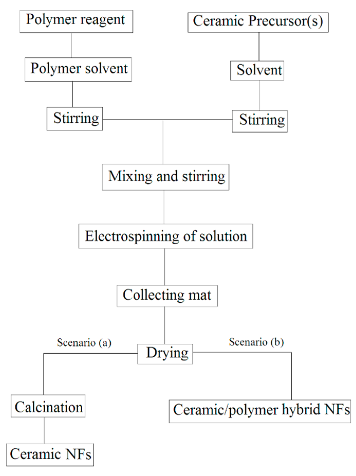
2. Types of Electrospun Ceramic Fibers
- (a)
- Single phase ceramic NFs are obtained by elimination of polymer reagent via a certain heat treatment procedure,
- (b)
- Ceramic/polymer hybrid NFs are synthesized without any more heat treatment.
2.1. Single Phase Ceramic Fibers
2.2. Composite Ceramic/Polymer Fibers
3. Fabrication of Electrospun Ceramic Mats
3.1. Assistant of Polymer
3.2. Electrospinning Parameters and Procedures
3.3. Calcination and Heat Treatment
3.4. Surface Modification of Electrospun Ceramic Mats
4. Characterization of Ceramic Electrospun Mats
4.1. Microstructure
4.2. Mechanical Properties
4.3. Physical Properties
4.3.1. Porosity
4.3.2. Gas Permeability
4.3.3. Water Permeability
4.3.4. Turbidity
4.3.5. Thermal Conductivity
4.3.6. Gas Sensing
4.3.7. Hydrophobicity
4.3.8. Zeta Potential
4.4. Electrical Properties
4.4.1. Dielectric Constant
4.4.2. Electrolyte Uptake
4.4.3. Ionic Conductivity
4.4.4. Battery Efficiency
4.4.5. Permittivity, Magnetic Permeability, and EMI Shielding Efficiency (SE)
4.4.6. Harvest Energy Performance
5. Applications of Ceramic Electrospun Mats
5.1. Catalysts and Photocatalysts
5.2. Filtration and Separation
5.3. Biomedical
5.4. Fuel Cells
5.5. Sensors
5.6. Batteries
5.7. Electronic Devices
5.8. Supercapacitors and Energy Harvesting Systems
5.9. Magnetic Parts
5.10. Dielectrics
5.11. Thermoelectric Materials
5.12. Conductive Wires
5.13. Wearable and Electronic Textiles
5.14. Other Applications
6. Summary and Future Perspectives
- ■
- Catalysts: TiO2, V2O5, ZnO, SnO2, CdTiO3, Bi2MoO6, Nb2O5, Gd2O3
- ■
- Filtration: TiO2, Al2O3, Clay, Fe3O4, SrFe12O19
- ■
- Biomedical: HA, CaO, SiOC, TiO2, ZnO
- ■
- Fuel Cells: Pr0.4Sr0.6Co0.2Fe0.7Nb0.1O3−δ, GdBaCo2O5+δ
- ■
- Sensors: SnO2, ZnO, TiO2, CeO2, NiO, LaMnO3
- ■
- Batteries: SiO2, Al2O3 SnO2, GeO2, BaTiO3, LaCoO3
- ■
- Electromagnetic devices: Cu2ZnSnS4, ZnO, BaO, La0.7Sr0.3MnO3, Ce0.96Fe0.04O2, BaFe12O19, CaCu3Ti4O12, ZrO2, La2CuO4
- ■
- Energy harvesting and capacitors: BaTiO3, MnO2, In2O3
- ■
- Wearable electric textiles: ZnO, Geraphene, CNT, BaTiO3, PZT
- ■
- Other applications: Al2O3, BaZrO3, SiO2, ZrC, CexSm1−xO2
Acknowledgments
Author Contributions
Conflicts of Interest
Abbreviation
| BMSC | Bone marrow mesenchymal stem cells | PDR | Parallel rotary disk |
| BSA | Bovine serum albumin | PE | Polyethylene |
| BJH | Barrett-Joyner-Halenda | PEDOT | Poly(3,4-ethylenedioxythiophene) |
| CA | Cellulose acetate | PEO | Polyethylene oxide |
| CF | Chloroform | PES | Polyethersulfone |
| CNF | Carbon Nano Fiber | PET | Polyethylene terephthalate |
| CNT | Carbon Nano Tube | PHBV | Poly(3-hydroxybutyrate-co-3-hydroxyvalerate) |
| CTFE | Chlorotrifluoroethylene | PLA | Poly(l-lactic) acid |
| DMF | Dimethylformamide | PLEDs | Polymer light-emitting diodes |
| DSC | Differential scanning calorimetry | PLGA | Poly(Lactide-co-Glycolide) |
| EMI | Electromagnetic interface | PMMA | Polymethylmethacrylate |
| FESEM | Field emission scanning electron microscopy | PPy | Polypyrrole |
| HA | Hydroxyapatite | PS | Polystyrene |
| IDEs | Interdigitated electrodes | PU | Polyurethane |
| I-DOPA | Levodopa | PVA | Polyvinylalcohol |
| ITO | Indium tin oxide | PVAc | Polyvinylacetate |
| LEDs | light-emitting diodes | PVB | Polyvinyl butyral |
| LIB | Lithium ion battery | PVC | Polyvinyl chloride |
| MB | Methylene blue | PVDF | Polyvinylidene fluoride |
| MIP | Mercury intrusion porosimetry | PVP | Polyvinylpyrrolidone |
| MO | Methylene orange | PZT | Lead zirconate titanate |
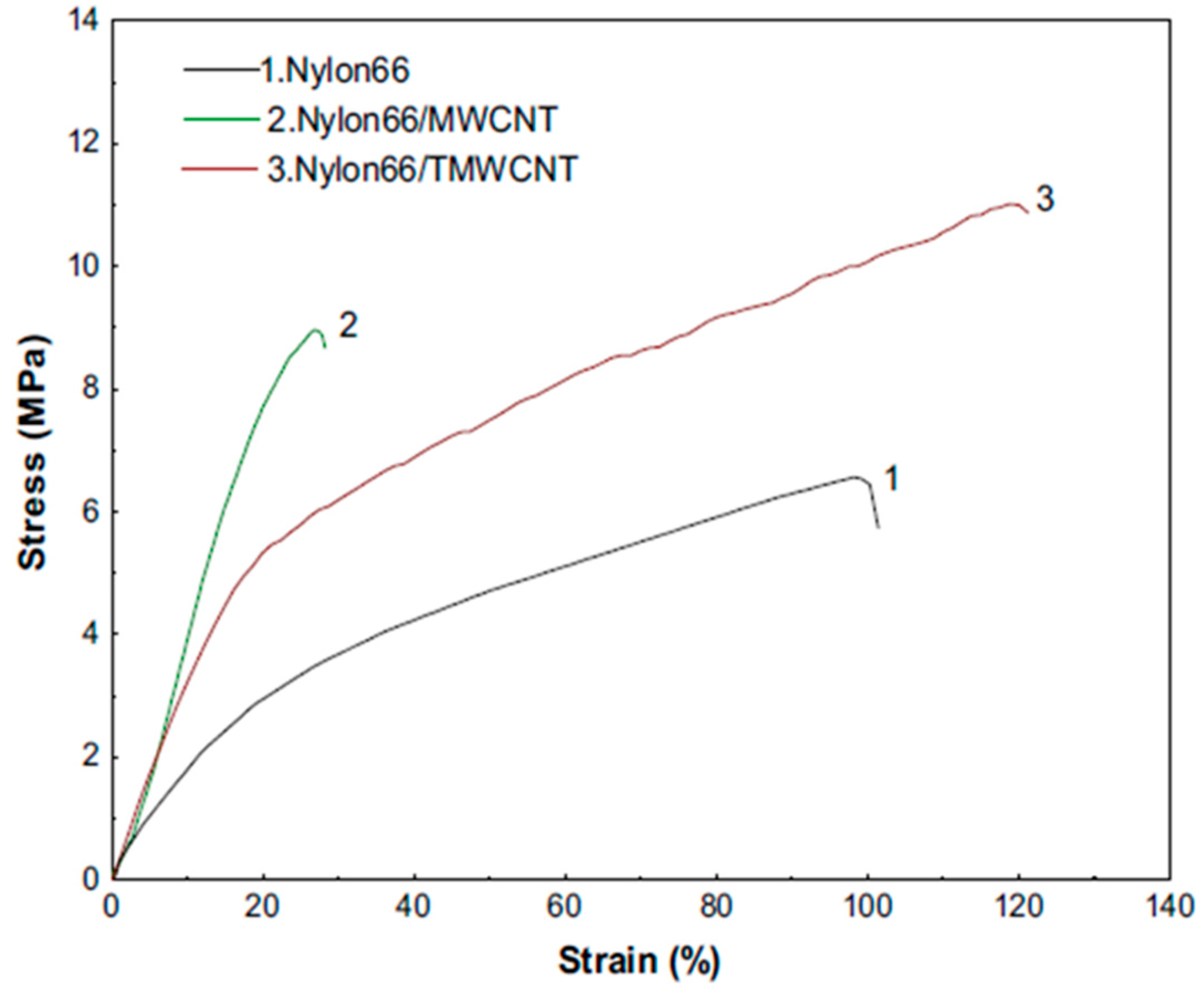
| MWCNT | Multi wall carbon nano tube | RhB | Rhodamine B |
| MX | Meloxicam | SAN | Poly(styrene-co-acrylonitrile) |
| NBs | Nano belts | SE | Shield effect |
| NCs | Nano crystallites | SEM | Scanning electron Microscopy |
| NFs | Nano fibers | SF | Solid fraction |
| NPLs | Nano plates | SOFC | Solid oxide fuel cell |
| NPs | Nano particles | SPEEK | Sulfonated polyether ether ketone |
| NTs | Nano tubes | STA | Simultaneous Thermal Analysis |
| NWs | Nano wires | TEM | Transition electron microscopy |
| P(VDF-HFD) | Poly(vinylidene fluoride-co-hexafluoropropylene) | TEOS | Tetraethoxysilane |
| PA6 | Nylon 6 | TG | Thermogravimetry |
| PA66 | Nylon 66 | TMWCNT | Treated multi wall carbon nano tube |
| PAN | Polyacrylonitrile | WGS | Water gas shift |
| PANI | Polyaniline | X-CT | X-ray computed tomography |
| PC | Polycarbonate | ZT | Thermoelectric properties |
| PCL | Polycaprolactone |
References
- Zhou, W.; Long, L.; Xiao, P.; Li, Y.; Luo, H.; Hu, W.; Rui, Y. Silicon carbide nano-fibers in-situ grown on carbon fibers for enhanced microwave absorption properties. Ceram. Int. 2017, 43, 5628–5634. [Google Scholar] [CrossRef]
- Moradipour, P.; Dabirian, F.; Rajabi, L.; Ashraf Derakhshan, A. Fabrication and characterization of new bulky layer mixed metal oxide ceramic nanofibers through two nozzle electrospinning method. Ceram. Int. 2016, 42, 13449–13458. [Google Scholar] [CrossRef]
- Ramaseshan, R.; Sundarrajan, S.; Jose, R.; Ramakrishna, S. Nanostructured ceramics by electrospinning. J. Appl. Phys. 2007, 102, 111101. [Google Scholar] [CrossRef]
- Brown, T.D.; Dalton, P.D.; Hutmacher, D.W. Melt electrospinning today: An opportune time for an emerging polymer process. Prog. Polym. Sci. 2016, 56, 116–166. [Google Scholar] [CrossRef]
- Hui, W.; Wei, P.; Dan, L.; He, L. Electrospinning of ceramic nanofibers: Fabrication, assembly and applications. J. Adv. Ceram. 2012, 1, 2–23. [Google Scholar] [CrossRef]
- Ikegame, M.; Tajima, K.; Aida, T. Template Synthesis of Polypyrrole Nanofibers Insulated within One-Dimensional Silicate Channels: Hexagonal versus Lamellar for Recombination of Polarons into Bipolarons. Chem. Int. Ed. 2003, 42, 2154–2157. [Google Scholar] [CrossRef] [PubMed]
- Hong, Y.; Legge, R.L.; Zhang, S.; Chen, P. Effect of Amino Acid Sequence and pH on Nanofiber Formation of Self-Assembling Peptides EAK16-II and EAK16-IV. Biomacromolecules 2003, 4, 1433–1442. [Google Scholar] [CrossRef] [PubMed]
- Ma, P.X.; Zhang, R. Synthetic nano-scale fibrous extracellular matrix. J. Biomed. Mater. Res. 1999, 46, 60–72. [Google Scholar] [CrossRef]
- Ellison, C.J.; Phatak, A.; Giles, D.W.; Macosko, C.W.; Bates, F.S. Melt blown nanofibers: Fiber diameter distributions and onset of fiber breakup. Polymer 2007, 48, 6180. [Google Scholar] [CrossRef]
- Ondarçuhu, T.; Joachim, C. Drawing a single nanofibre over hundreds of microns. EPL 1998, 42, 215. [Google Scholar] [CrossRef]
- Ramakrishna, S.; Ramalingam, M.; Sampath Kumar, T.S. Biomaterials: A Nano Approach; CRC Press: Boca Raton, FL, USA, 2010; p. 239. ISBN 9781420047813. [Google Scholar]
- Hong, Q.; Su, W.; Zhan, H. Coaxial electrospun nanostructures and their applications. J. Mater. Chem. A 2013, 1, 11513–11528. [Google Scholar]
- Sigmund, W.; Yuh, J.; Park, H.; Maneeratana, V.; Pyrgiotakis, G.; Daga, A.; Taylor, J.; Nino, J.C. Processing and Structure Relationships in Electrospinning of Ceramic Fiber Systems. J. Am. Ceram. Soc. 2006, 89, 395–407. [Google Scholar] [CrossRef]
- Biswas, A.; Park, H.; Sigmund, W.M. Flexible ceramic nanofibermat electrospun from TiO2–SiO2 aqueous sol. Ceram. Int. 2012, 38, 883–886. [Google Scholar] [CrossRef]
- Musiari, F.; Pirondi, A.; Morini, F.; Giuliese, G.; Zucchelli, A.; Brugo, T.M.; Minak, G.; Ragazzini, C. Feasibility study of adhesive bonding reinforcement by electrospun nanofibers. Procedia Struct. Integr. 2016, 2, 112–119. [Google Scholar] [CrossRef]
- Esfahani, H.; Prabhakaran, M.P.; Salahi, E.; Tayebifard, A.; Rahimipour, M.R.; Keyanpour-Rad, M.; Ramakrishna, S. Electrospun nylon 6/zinc doped hydroxyapatite membrane for protein separation: Mechanism of fouling and blocking model. Mater. Sci. Eng. C 2016, 59, 420–428. [Google Scholar] [CrossRef] [PubMed]
- Chen, Z.; Zhao, Z.; Chen-Chih, T.; Konstantin, K.; Igor, L.; Fang, M.; Peng, F. Electrospun mullite fibers from the sol–gel precursor. J. Sol-Gel Sci. Technol. 2015, 74, 208–219. [Google Scholar] [CrossRef]
- Zhang, H.; Hang, Y.; Qin, Y.; Yang, J.; Wang, B. Synthesis and characterization of sol–gel derived continuous spinning alumina based fibers with silica nano-powders. J. Eur. Ceram. Soc. 2014, 34, 465–473. [Google Scholar] [CrossRef]
- Yaipimai, W.; Pornprasertsuk, R. Fabrication of Pt, Pt–Cu, and Pt–Sn nanofibers for direct ethanol protonic ceramic fuel cell application. J. Mater. Sci. 2013, 48, 4059–4072. [Google Scholar] [CrossRef]
- Ashraf, A.; Awad, K.; Asmari, A. Wet-electrospun CuNP/carbon nanofibril composites: Potential application for micro surface-mounted components. Appl. Nanosci. 2012, 2, 55–56. [Google Scholar] [CrossRef]
- Ghashghaie, S.; Bazargan, A.M.; Esmaeilpour Ganji, M.; Marzbanrad, E.; Zamani, C.; Raissi, B.; Keyanpour-rad, M.; Bahrevar, M.A. An investigation on the behavior of electrospun ZnO nanofibers under the application of low frequency AC electric fields. J. Mater. Sci. Mater. Electron. 2011, 22, 1303–1307. [Google Scholar] [CrossRef]
- Kim, J.H.; Yoo, S.J.; Kwak, D.H.; Jung, H.J.; Kim, T.Y.; Park, K.H.; Lee, J.W. Characterization and application of electrospun alumina nanofibers. Nanoscale Res. Lett. 2014, 9, 44. [Google Scholar] [CrossRef] [PubMed]
- Milanovic, P.; Dimitrijevic, M.; Heinemann, R.; Rogan, J.; Stojanovic, D.; Kojovic, A.; Aleksic, R. Preparation of low cost alumina nanofibers via electrospinning of aluminium chloride hydroxide/poly (vinyl alcohol) solution. Ceram. Int. 2013, 39, 2131–2134. [Google Scholar] [CrossRef]
- Zhang, P.; Jiao, X.; Chen, D. Fabrication of electrospun Al2O3 fibers with CaO–SiO2 additive. Mater. Lett. 2013, 91, 23–26. [Google Scholar] [CrossRef]
- Liu, G.F.; Zhang, Z.D.; Dang, F.; Cheng, C.B.; Hou, C.; Liu, S.D. Formation and characterization of magnetic barium ferrite hollow fibers with low coercivity via co-electrospun. J. Magn. Magn. Mater. 2016, 412, 55–62. [Google Scholar] [CrossRef]
- Calleja, A.; Sort, J.; Ricart, J.; Granados, X.; Palmer, X.; Roxana Vlad, V.; Puig, T.; Obradors, X. Composite films combining electrospun fiber network and epitaxial oxide by chemical solution deposition. J. Sol-Gel Sci. Technol. 2016, 1, 11. [Google Scholar] [CrossRef]
- Wang, W.; Chi, N.; Li, Y.; Yan, W.; Li, X.; Shao, C. Electrospinning of magnetical bismuth ferrite nanofibers with photocatalytic activity. Ceram. Int. 2013, 39, 3511–3518. [Google Scholar] [CrossRef]
- Cinar, E.; Koc, S.; It, S.; Aytimur, A.; Uslu, I.; Akdemir, A. Synthesis, Characterization, and Thermoelectric Properties of Electrospun Boron-Doped Barium-Stabilized Bismuth-Cobalt Oxide Nanoceramics. Metall. Mater. Trans. A 2014, 45, 3929. [Google Scholar] [CrossRef]
- Wang, J.; Yang, Y.; Huang, Z.; Kang, F. Coaxial carbon nanofibers/MnO2 nanocomposites as freestanding electrodes for high-performance electrochemical capacitors. Electrochim. Acta 2011, 56, 9240–9247. [Google Scholar] [CrossRef]
- Qin, D.; Liang, G.; Gu, A. CaCu3Ti4O12 electrospun fibre: A new form of CaCu3Ti4O12 and its dielectric property. J. Alloys Compd. 2013, 549, 11–17. [Google Scholar] [CrossRef]
- Mohammadi, M.; Alizadeh, P.; Clemens, F.J. Effect of using different precursors on electrospinning of CaCu3Ti4O12. Ceram. Int. 2016, 42, 4690–4699. [Google Scholar] [CrossRef]
- Shamshi Hassan, M.; Amna, T.; SeobKhil, M.Y. Synthesis of High aspect ratio CdTiO3 nanofibers via electrospinning: Characterization and photocatalytic activity. Ceram. Int. 2014, 40, 423–427. [Google Scholar] [CrossRef]
- Sonsupap, S.; Kidkhunthod, P.; Chanlek, N.; Pinitsoontorn, S.; Maensiri, S. Fabrication, structure, and magnetic properties of electrospun Ce0.96Fe0.04O2 nanofibers. Appl. Surf. Sci. 2016, 380, 16–22. [Google Scholar] [CrossRef]
- AbiJaoude, M.; Polychronopoulou, K.; Hinder, S.J.; Katsiotis, M.S.; Baker, M.A.; Greish, Y.E.; Alhassan, S.M. Synthesis and properties of 1D Sm-doped CeO2 composite nanofibers fabricated using a coupled electrospinning and sol–gel methodology. Ceram. Int. 2016, 42, 10734–10744. [Google Scholar] [CrossRef]
- Ju, Y.; Park, J.; Jung, H.; Cho, S.; Lee, W. Fabrication and characterization of cobalt ferrite (CoFe2O4) nanofibers by electrospinning. Mater. Sci. Eng. B 2008, 147, 7–12. [Google Scholar] [CrossRef]
- Chiu, T.; Tu, C.; Chen, Y. Fabrication of electrospun CuCr2O4 fibers. Ceram. Int. 2015, 41, S399–S406. [Google Scholar] [CrossRef]
- Schutz, P.; Alves, A.K.; Bergmann, C.P. Effect of the in-air heat treatment in the phase formation and morphology of electrospun Cu2ZnSnS4 fibers. Ceram. Int. 2014, 40, 11551–11557. [Google Scholar] [CrossRef]
- Jiang, X.; Xu, H.; Wang, Q.; Jiang, L.; Li, X.; Xu, Q.; Shi, Y.; Zhang, Q. Fabrication of GdBaCo2O5+d cathode using electrospun composite nanofibers and its improved electrochemical performance. J. Alloys Compd. 2013, 557, 184–189. [Google Scholar] [CrossRef]
- Lei, D.; Qu, B.; Lin, H.T.; Wang, T. Facile approach to prepare porous GeO2/SnO2 nanofibers via a single spinneret electrospinning technique as anodes for Lithium-ion batteries. Ceram. Int. 2015, 41, 10308–10313. [Google Scholar] [CrossRef]
- Franco, P.Q.; Joao, C.F.C.; Silva, J.C.; Borges, J.P. Electrospun hydroxyapatite fibers from a simple sol-gel system. Mater. Lett. 2012, 67, 233–236. [Google Scholar] [CrossRef]
- Gibbons, W.T.; Liu, T.H.; Gaskell, K.J.; Jackson, G.S. Characterization of palladium/copper/ceria electrospun fibers for water-gas shift catalysis. Appl. Catal. B Environ. 2014, 160–161, 465–479. [Google Scholar] [CrossRef]
- Shim, J.; Lopez, K.J.; Sun, H.-J.; Park, G.; An, J.-C.; Eom, S.; Shimpalee, S.; Weidner, J.W. Preparation and characterization of electrospun LaCoO3 fibers for oxygen reduction and evolution in rechargeable Zn-air batteries. Appl. Electrochem. 2015, 45, 1005–1012. [Google Scholar] [CrossRef]
- Hayat, K.; Niaz, F.; Ali, S.; Iqbal, M.; Ajmal, M.; Ali, M.; Iqbal, Y. Thermoelectric performance and humidity sensing characteristics of La2CuO4 nanofibers. Sens. Actuator B 2016, 231, 102–109. [Google Scholar] [CrossRef]
- Xu, D.; Luo, L.; Ding, Y.; Jiang, L.; Zhang, Y.; Ouyang, X.; Liu, B. A novel nonenzymatic fructose sensor based on electrospun LaMnO3 Fibers. J. Electron. Chem. 2014, 727, 21–26. [Google Scholar] [CrossRef]
- Yensano, R.; Pinitsoontorn, S.; Amornkitbamrung, V.; Maensiri, S. Fabrication and Magnetic Properties of Electrospun La0.7Sr0.3MnO3 Nanostructures. J. Supercond. Nov. Magn. 2014, 27, 1553–1560. [Google Scholar] [CrossRef]
- Yuan, K.; Feng, C.; Gan, X.; Yu, Z.; Wang, X.; Zhu, L.; Zhang, G.; Xu, D. Fabrication of La2Zr2O7 ceramic fibers via electrospinning method using different La2O3 precursors. Ceram. Int. 2016, 42. [Google Scholar] [CrossRef]
- Sorour, M.H.; Rafei, A.M.E.L.; Hani, H. Synthesis and characterization of electrospun aluminum doped Li1.6Mn1.6O4 spinel. Ceram. Int. 2016, 42, 4911–4917. [Google Scholar] [CrossRef]
- Lu, Q.; Liu, Q.; Wei, Q.; Liu, G.; Zhuang, J. Preparation and characterization of Lu2SiO5:Ce3+ luminescent ceramic fibers via electrospinning. Ceram. Int. 2013, 39, 8159–8164. [Google Scholar] [CrossRef]
- Mohammad Ali Zadeh, M.; Keyanpour-Rad, M.; Ebadzadeh, T. Synthesis of mullite nanofibres by electrospinning of solutions containing different proportions of polyvinyl butyral. Ceram. Int. 2013, 39, 9079–9084. [Google Scholar] [CrossRef]
- Rafei, A.M.E.L. Optimization of the electrospinning parameters of Mn2O3 and Mn3O4 nanofibers. Ceram. Int. 2015, 4, 12065–12072. [Google Scholar] [CrossRef]
- Leindecker, G.C.; Alves, A.K.; Bergmann, C.P. Synthesis of niobium oxide fibers by electrospinning and characterization of their morphology and optical properties. Ceram. Int. 2014, 40, 16195–16200. [Google Scholar] [CrossRef]
- Ristic, M.; Marcius, M.; Petrovic, Z.; Music, S. Dependence of NiO microstructure on the electrospinning conditions. Ceram. Int. 2014, 40, 10119–10123. [Google Scholar] [CrossRef]
- George, G.; Anandhan, S. Electrospun nickel oxide nanofiber webs for thermistor applications. Int. J. Plast. Technol. 2014, 18, 374–382. [Google Scholar] [CrossRef]
- Wang, Z.; Hu, X.; Dong, D.; Parkinson, G.; Li, C. Effects of calcination temperature of electrospun fibrous Ni/Al2O3 catalysts on the dry reforming of methane. Fuel Proc. Technol. 2017, 155, 246–251. [Google Scholar] [CrossRef]
- Liu, X.; Li, M.; Wang, Z.; Zhang, C.; Xiong, Y. Electro-spinning Pr0.4Sr0.6Co0.2Fe0.7Nb0.1O3-δ nanofibers infiltrated with Gd0.2Ce0.8O1.9 nanoparticles as cathode for intermediate temperature solid oxide fuel cell. Ceram. Int. 2016, 42, 11907–11912. [Google Scholar] [CrossRef]
- Mauro, A.D.; Fragala, M.E. Electrospun SiO2 ‘‘necklaces’’ on unglazed ceramic tiles: A planarizing strategy. Superlattices Microst. 2015, 81, 265–271. [Google Scholar] [CrossRef]
- Guo, A.; Roso, M.; Modesti, M.; Maire, E.; Adrien, J.; Colombo, P. Characterization of porosity, structure, and mechanical properties of electrospun SiOC fiber mats. J. Mater. Sci. 2015, 50, 4221–4231. [Google Scholar] [CrossRef]
- Guo, A.; Roso, M.; Colombo, P.; Liu, J.; Modesti, M. In situ carbon thermal reduction method for the production of electrospun metal/SiOC composite fibers. J. Mater. Sci. 2015, 50, 2735–2746. [Google Scholar] [CrossRef]
- Zhao, J.; Liu, Z.; Lu, Q. Electrospun 1D SiO2 doped Bi2MoO6 microbelts for highly efficient photocatalytic applications. Dyes Pigment. 2016, 134, 553–561. [Google Scholar] [CrossRef]
- Kim, I.; Jeon, E.K.; Choi, S.H.; Choi, D.K.; Tuller, H.L. Electrospun SnO2 nanofiber mats with thermo-compression step for gas sensing applications. Electroceram 2010, 25, 159–167. [Google Scholar] [CrossRef]
- Xu, X.; Sun, J.; Zhang, H.; Wang, X.; Dong, B.; Jiang, T.; Wang, W.; Li, Z.; Wang, C. Effects of Al doping on SnO2 nanofibers in hydrogen sensor. Sens. Actuator B 2011, 160, 858–863. [Google Scholar] [CrossRef]
- Mohanapriya, P.; Segawa, H.; Watanabe, K.; Watanabe, K.; Samitsu, S.; Natarajan, T.S.; Victor Jaya, N.; Ohashi, N. Enhanced ethanol-gas sensing performance of Ce-doped SnO2 hollow nanofibers prepared by electrospinning. Sens. Actuator B 2013, 188, 872–878. [Google Scholar] [CrossRef]
- Jiang, Z.; Zhao, R.; Sun, B.; Nie, G.; Ji, H.; Lei, J.; Wang, C. Highly sensitive acetone sensor based on Eu-doped SnO2 electrospun nanofibers. Ceram. Int. 2016, 42, 15881–15888. [Google Scholar] [CrossRef]
- Panda, P.K. Preparation and characterization of Samaria nanofibers by electrospinning. Ceram. Int. 2013, 39, 4523–4527. [Google Scholar] [CrossRef]
- Li, C.J.; Wang, J.N.; Li, X.Y.; Zhang, L.L. Functionalization of electrospun magnetically separable TiO2-coated SrFe12O19 nanofibers: Strongly effective photocatalyst and magnetic separation. J. Mater. Sci. 2011, 46, 2058–2063. [Google Scholar] [CrossRef]
- Zhao, K.; Teng, L.; Tang, Y.; Chen, X. Branched titanium oxide/vanadium oxide composite nanofibers formed by electrospinning and dipping in vanadium sol. Ceram. Int. 2014, 40, 15335–15340. [Google Scholar] [CrossRef]
- Tikekar, N.M.; Lannutti, J.J. Effects of humidity on titania-based polyvinylpyrolidone (PVP) electrospun fibers. Ceram. Int. 2012, 38, 4057–4064. [Google Scholar] [CrossRef]
- Arvand, M.; Ghodsi, N. Electrospun TiO2 nanofiber/graphite oxide modified electrode for electrochemical detection of l-DOPA in human cerebrospinal fluid. Sens. Actuator B 2014, 204, 393–401. [Google Scholar] [CrossRef]
- Giancaterini, L.; Emamjomeh, S.M.; Marcellis, A.; Palange, E.; Resmini, A.; Anselmi-Tamburini, U.; Cantalini, C. The influence of thermal and visible light activation modes on the NO2 response of WO3 nanofibers prepared by electrospinning. Sens. Actuator B 2016, 229, 387–395. [Google Scholar] [CrossRef]
- Szilagyi, I.M.; Santala, E.; Heikkila, M.; Kemell, M.; Nikitin, T.; Khriachtchev, L.; Rasanen, M.; Ritala, M.; Leskela, M. Thermal study on electrospun polyvinylpyrrolidone/ammonium metatungstate nanofibers: Optimising the annealing conditions for obtaining WO3 nanofibers. J. Therm. Anal. Calorim. 2011, 105, 73–81. [Google Scholar] [CrossRef]
- Henriques, M.S.; Ferreira, A.C.; Cruz, A.; Ferreira, L.M.; Branco, J.B.; Brazda, P.; Jurek, K.; Stora, T.; Goncalves, A.P. Preparation of Yb2O3 submicron- and nano-materials via electrospinning. Ceram. Int. 2015, 41, 10795–10802. [Google Scholar] [CrossRef]
- Stafiniak, A.; Boratynsk, B.; Korczyc, A.B.; Szyszka, A.; Krasowska, M.; Prazmowska, J.; Fronc, K.; Elbaum, D.; Paszkiewicz, R.; Tłaczała, M. A novel electrospun ZnO nanofibers biosensor fabrication. Sens. Actuator B 2011, 160, 1413–1418. [Google Scholar] [CrossRef]
- Cao, Y.; Zou, X.; Wang, X.; Qian, J.; Bai, N.; Li, G.D. Effective detection of trace amount of explosive nitro-compounds by ZnO nanofibers with hollow structure. Sens. Actuator B 2016, 232, 564–570. [Google Scholar] [CrossRef]
- Nixon Samuel Vijayakumar, G.; Rathnakumar, M.; Sureshkumar, P. Electrical and non-linear optical studies on electrospun ZnO/BaO composite nanofibers. Front. Mater. Sci. 2012, 6, 69–78. [Google Scholar] [CrossRef]
- Luo, L.; Xu, W.; Xia, Z.; Fei, Y.; Zhu, J.; Chen, C.; Lu, Y.; Wei, Q.; Qiao, H.; Zhang, X. Electrospun ZnO–SnO2 composite nanofibers with enhanced electrochemical performance as lithium-ion anodes. Ceram. Int. 2016, 42, 10826–10832. [Google Scholar] [CrossRef]
- Sebnem Cetin, S.; Uslu, I.; Aytimur, A.; Ozcelik, S. Characterization of Mg doped ZnO nanocrystallites prepared via Electrospinning. Ceram. Int. 2012, 38, 4201–4208. [Google Scholar] [CrossRef]
- Wu, Y.; Dong, Z.; Jenness, N.J.; Clark, R.L. In-situ formation of Cu metal crystals within nanostructured ZnO electrospun fibers. Mater. Lett. 2011, 65, 2683–2685. [Google Scholar] [CrossRef]
- Li, F.; Kang, Z.; Huang, X.; Zhang, G.J. Fabrication of zirconium carbide nanofibers by electrospinning. Ceram. Int. 2014, 40, 10137–10141. [Google Scholar] [CrossRef]
- Singh, S.; Singh, S.; Vijayakumar, M.; Bhanu Prasad, V.V. Electrospun ZrO2 fibers obtained from polyvinyl alcohol/zirconium n-propoxide composite fibers processed through halide free sol–gel route using acetic acid as a stabilizer. Mater. Lett. 2014, 115, 64–67. [Google Scholar] [CrossRef]
- Chou, C.C.; Huang, C.F.; Yeh, T.H. Characterization and catalytic activity of La0.6Sr0.4Co0.2Fe0.8O3-d–yttria stabilized zirconia electrospun nano-fiber as a cathode catalyst. Ceram. Int. 2013, 39, S549–S553. [Google Scholar] [CrossRef]
- Li, J.Y.; Tan, Y.; Xu, F.M.; Sun, Y.; Cao, X.Q.; Zhang, Y.F. Hollow fibers of yttria-stabilized zirconia (8YSZ) prepared by calcination of electrospun composite fibers. Mater. Lett. 2008, 62, 2396–2399. [Google Scholar] [CrossRef]
- Vivekanandhan, S.; Schreiber, M.; Kumar Mohanty, A.; Misra, M. Advanced Electrospun Nanofibers of Layered Silicate Nano Composites: A Review of Processing, Properties, and Applications. In Handbook of Polymer Nanocomposites, Processing, Performance and Application; Pandey, J.K., Ed.; Springer: Berlin/Heidelberg, Germany, 2014; pp. 361–388. [Google Scholar]
- Balasubramanian, P.; Roether, J.A.; Schubert, D.W.; Beier, J.P.; Boccaccini, A.R. Bi-layered porous constructs of PCL-coated 45S5 bioactive glass and electrospun collagen-PCL fibers. J. Porous Mater. 2015, 22, 1215–1226. [Google Scholar] [CrossRef]
- Promphet, N.; Rattanarat, P.; Rangkupan, R.; Chailapakul, O.; Rodthongkum, N. An electrochemical sensor based ongraphene/polyaniline/polystyrene nanoporous fibers modifiedelectrode for simultaneous determination of lead and cadmium. Sens. Actuator B 2015, 207, 526–534. [Google Scholar] [CrossRef]
- Albetran, H.; Dong, Y.; Low, I.M. Characterization and optimization of electrospun TiO2/PVP nano fibers using Taguchi design of experiment method. J. Asian Ceram. Soc. 2015, 3, 292–300. [Google Scholar] [CrossRef]
- Lee, Y.S.; Jeong, Y.B.; Kim, D.W. Cycling performance of lithium-ion batteries assembled with a hybrid composite membrane prepared by an electrospinning method. J. Power Sources 2010, 195, 6197–6201. [Google Scholar] [CrossRef]
- Kurtycz, P.; Ciach, T.; Olszyna, A.; Kunicki, A.; Radziun, E.; Roslon, M.; Dudkiewicz-Wilczynska, J.; Nowak, K.; Anuszewska, E. Electrospun Poly(l-lactic)Acid/Nanoalumina (PLA/Al2O3) Composite Fiber Mats with Potential Biomedical Application—Investigation of Cytotoxicity. Fiber Polym. 2013, 14, 578–583. [Google Scholar] [CrossRef]
- Sun Im, J.; Gu Kim, J.; Bae, T.S.; Lee, Y.S. Effect of heat treatment on ZrO2-embedded electrospun carbon fibers used for efficient electromagnetic interference shielding. J. Phys. Chem. Sol. 2011, 72, 1175–1179. [Google Scholar] [CrossRef]
- Suslu, A.; Albayrak, A.Z.; Urkmez, A.S.; Bayir, E.; Cocen, U. Effect of surfactant types on the biocompatibility of electrospun HAp/PHBV composite nanofibers. J. Mater. Sci. Mater. Med. 2014, 25, 2677–2689. [Google Scholar] [CrossRef] [PubMed]
- Xu Yan, J.Z.; Li, M.M.; Yu, G.F.; Zhang, H.D.; Pisula, W.; He, X.X.; Duvail, J.; Long, Y.Z. Electrospun Aligned Fibrous Arrays and Twisted Ropes: Fabrication, Mechanical and Electrical Properties, and Application in Strain Sensors. Nanoscale Res. Lett. 2015, 10, 475. [Google Scholar] [CrossRef]
- Raghavan, P.; Zhao, X.; Manuel, J.; Chauhan, G.S.; Ahn, J.H.; Ryu, H.S.; Ahn, H.J.; Kim, K.W.; Nah, C. Electrochemical performance of electrospun poly(vinylidene fluoride-co-exafluoropropylene)-based nanocomposite polymer electrolytes incorporating ceramic fillers and room temperature ionic liquid. Electrochim. Acta 2010, 55, 1347–1354. [Google Scholar] [CrossRef]
- Lee, C.; Wood, D.; Edmondson, D.; Yao, D.; Erickson, A.E.; Tsao, C.T.; Revia, R.A.; Kim, H.; Zhang, M. Electrospun uniaxially-aligned composite nanofibers as highly-efficient piezoelectric material. Ceram. Int. 2016, 42, 2734–2740. [Google Scholar] [CrossRef]
- Nunes-Pereira, J.; Sencadas, V.; Correia, V.; Rocha, J.G.; Lanceros-Mendez, S. Energy harvesting performance of piezoelectric electrospun polymer fibers and polymer/ceramic composites. Sens. Actuator A 2013, 196, 55–62. [Google Scholar] [CrossRef]
- Hota, G.; Kumar, B.R.; Ng, W.G.; Ramakrishna, S. Fabrication and characterization of a boehmite nanoparticle impregnated electrospun fiber membrane for removal of metal ions. J. Mater. Sci. 2008, 43, 212–217. [Google Scholar] [CrossRef]
- Nirmala, R.; Jeon, K.S.; Lim, B.H.; Navamathavan, R.; Kim, H.Y. Preparation and characterization of copper oxide particles incorporated polyurethane composite nanofibers by electrospinning. Ceram. Int. 2013, 39, 9651–9658. [Google Scholar] [CrossRef]
- Ben Hassan, S.A.; Stojanovic, D.B.; Kojovic, A.; Astvan, I.A.; Janackovic, D.; Uskokovic, P.S.; Aleksic, R. Preparation and characterization of poly(vinylbutyral) electrospun nanocomposite fibers reinforced with ultrasonically functionalized sepiolite. Ceram. Int. 2014, 40, 1139–1146. [Google Scholar] [CrossRef]
- Mohammadi, M.; Alizadeh, P.; Clemens, F.J. Synthesis of CaCu3Ti4O12 nanofibers by electrospinning. Ceram. Int. 2015, 41, 13417–13424. [Google Scholar] [CrossRef]
- Sangkhaprom, N.; Supaphol, P.; Pavarajarn, V. Fibrous zinc oxide prepared by combined electrospinning and solvothermal techniques. Ceram. Int. 2010, 36, 357–363. [Google Scholar] [CrossRef]
- Khalil, A.; Kim, J.J.; Tuller, H.L.; Rutledge, G.C.; Hashaikeh, R. Gas sensing behavior of electrospun nickel oxide nanofibers: Effect of morphology and microstructure. Sens. Actuator B 2016, 227, 54–64. [Google Scholar] [CrossRef]
- Saleemi, A.S.; Abdullah, A.; Shah, S.M.H.; Anis-ur-Rehman, M. Electrospun Proficient Polymer Based Nano Fibers with Ceramic Particles. J. Supercond. Nov. Magn. 2013, 26, 1027–1030. [Google Scholar] [CrossRef]
- Starbova, K.; Petrov, D.; Starbov, N.; Lovchinov, V. Synthesis of supported fibrous nanoceramics via electrospinning. Ceram. Int. 2012, 38, 4645–4651. [Google Scholar] [CrossRef]
- Lamastra, F.R.; Nanni, F.; Menchini, F.; Nunziante, P.; Grilli, M.L. Transparent nanostructured electrodes: Electrospun NiO nanofibers/NiO films. Thin Solid Film 2015, 601, 54–58. [Google Scholar] [CrossRef]
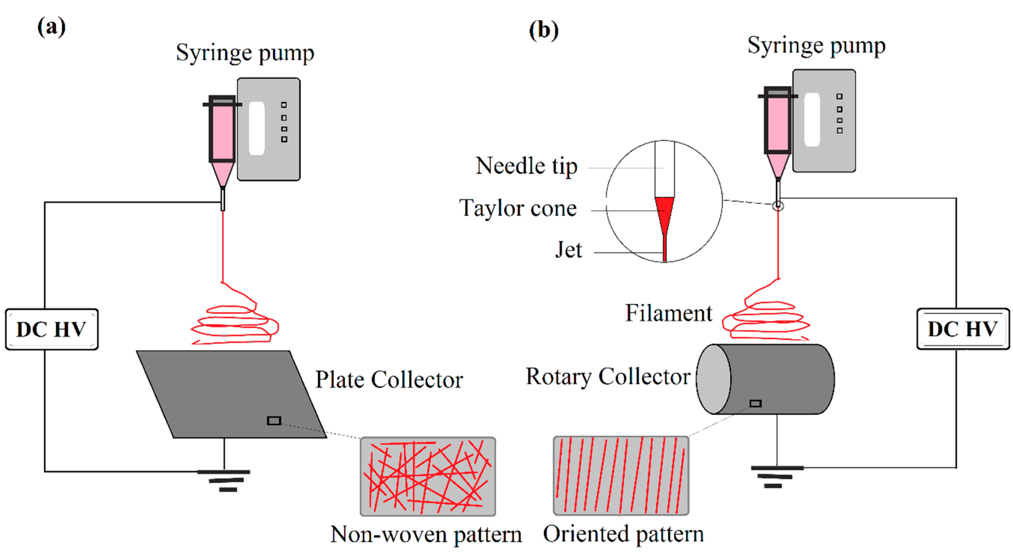
- Laudenslager, M.J.; Sigmund, W.M. A continuous process to align electrospun nanofibers into parallel and crossed arrays. J. Nanopart. Res. 2013, 15, 1487. [Google Scholar] [CrossRef]
- Teo, W.E.; Ramakrishna, S. A review on electrospinning design and nanofibre assemblies. Nanotechnology 2006, 17, R89. [Google Scholar] [CrossRef] [PubMed]
- Shin, H.U.; Ramsier, R.D.; Chase, G.G. Influence of calcination temperature on the surface area of submicron-sized Al2O3 electrospun fibers. Appl. Phys. A 2016, 122, 145. [Google Scholar] [CrossRef]
- Dai, Y.; Liu, W.; Formo, E.; Sun, Y.; Xia, Y. Ceramic nanofibers fabricated by electrospinning and their applications in catalysis, environmental science, and energy technology. Polym. Adv. Technol. 2011, 22, 326–338. [Google Scholar] [CrossRef]
- Min, J.W.; Yim, C.J.; BinIm, W. Preparation and electrochemical characterization of flower-like Li1.2Ni0.17Co0.17Mn0.5O2 microstructure cathode by electrospinning. Ceram. Int. 2014, 40, 2029–2034. [Google Scholar] [CrossRef]
- Eick, B.M.; Youngblood, J.P. SiC nanofibers by pyrolysis of electrospun preceramic polymers. J. Mater. Sci. 2009, 44, 160–165. [Google Scholar] [CrossRef]
- Khalil, K.A.; Sherif, E.M.; Nabawy, A.M.; Abdo, H.S.; Marzouk, W.W.; Alharbi, H.F. Titanium Carbide Nanofibers-Reinforced Aluminum Compacts, a New Strategy to Enhance Mechanical Properties. Materials 2016, 9, 399. [Google Scholar] [CrossRef] [PubMed]
- Guo, A.; Roso, M.; Modesti, M.; Liu, J.; Colombo, P. Hierarchically structured polymer-derived ceramic fibers by electro spinning and catalyst-assisted pyrolysis. J. Eur. Ceram. Soc. 2014, 34, 549–554. [Google Scholar] [CrossRef]
- Petrovic, Z.; Ristic, M.; Marcius, M.; MileIvanda Durina, V.; Music, S. Hydrothermal processing of electrospun fibers in the synthesis of 1D ZnO nanoparticles. Mater. Lett. 2016, 176, 278–281. [Google Scholar] [CrossRef]
- Sun, Y.; Li, J.Y.; Tan, Y.; Zhang, L. Fabrication of aluminum nitride (AlN) hollow fibers by carbothermal reduction and nitridation of electrospun precursor fibers. J. Alloys Compd. 2009, 471, 400–403. [Google Scholar] [CrossRef]
- Li, J.Y.; Sun, Y.; Tan, Y.; Xu, F.M.; Shi, X.L.; Ren, N. Zirconium nitride (ZrN) fibers prepared by carbothermal reduction and nitridation of electrospun PVP/zirconium oxychloride composite fibers. Chem. Eng. J. 2008, 144, 149–152. [Google Scholar] [CrossRef]
- Qin, D.; Liang, G.; Gu, A.; Yuan, L. Facilely preparing various new titania electrospun fibers with controllable nanostructures using a three-step method. Sol-Gel Sci. Technol. 2013, 67, 451–457. [Google Scholar] [CrossRef]
- Huang, Z.; Chen, Y.; Zhou, W.; Nie, H.; Hu, Y. Preparation of silica hollow fibers by surface-initiated atom transfer radical polymerization from electrospun fiber templates. Mater. Lett. 2009, 63, 1803–1806. [Google Scholar] [CrossRef]
- Fan, X.X.; He, X.L.; Li, J.P.; Gao, X.J.; Jia, J. Ethanol sensing properties of hierarchical SnO2 fibers fabricated with electrospun polyvinylpyrrolidone template. Vacuum 2016, 128, 112–117. [Google Scholar] [CrossRef]
- Wang, S.H.; Wan, Y.; Sun, B.; Liu, L.Z.; Xu, W. Mechanical and electrical properties of electrospun PVDF/MWCNT ultrafine fibers using rotating collector. Nanoscale Res. Lett. 2014, 9, 522. [Google Scholar] [CrossRef] [PubMed]
- Chronakis, I.S. Novel nanocomposites and nanoceramics based on polymer nanofibers using electrospinning process—A review. J. Mater. Process. Technol. 2005, 167, 283–293. [Google Scholar] [CrossRef]
- Xiang, C.; Frey, M.W. Increasing Mechanical Properties of 2-d-Structured Electrospun Nylon 6 Non-Woven Fiber Mats. Materials 2016, 9, 270. [Google Scholar] [CrossRef] [PubMed]
- Neppalli, R.; Causin, V.; Benetti, E.M.; Ray, S.S.; Esposito, A.; Wanjale, S.; Birajdar, M.; Saiter, J.M.; Marigo, A. Polystyrene/TiO2 composite electrospun fibers as fillers for poly(butylene succinate-co-adipate): Structure, morphology and properties. Eur. Polym. J. 2014, 50, 78–86. [Google Scholar] [CrossRef]
- Nanni, F.; Lamastra, F.R.; Pisa, F.; Gusmano, G. Synthesis and characterization of poly(e-caprolactone) reinforced with aligned hybrid electrospun PMMA/nano-Al2O3 fibre mats by film stacking. J. Mater. Sci. 2011, 46, 6124–6130. [Google Scholar] [CrossRef]
- Yang, W.; Sousa, A.M.M.; Thomas-Gahring, A.; Fan, X.; Jin, T.; Li, T.; Tomasula, P.M.; Liu, L.S. Electrospun Polymer Nanofibers Reinforced by Tannic Acid/Fe+++ Complexes+. Materials 2016, 9, 757. [Google Scholar] [CrossRef] [PubMed]
- Gopal, R.; Kaur, S.; Ma, Z.; Chan, C.; Ramakrishna, S.; Matsuura, T. Electrospun nano fibrous filtration membrane. J. Membr. Sci. 2006, 281, 581–586. [Google Scholar] [CrossRef]
- Mota, C.; Labardi, M.; Trombi, L.; Astolfi, L.; Acunto, M.; Puppi, D.; Gallone, G.; Chiellini, F.; Berrettini, S.; Bruschini, L.; et al. Design, fabrication and characterization of composite piezoelectric ultrafine fibers for cochlear stimulation. Mater. Des. 2017, 122, 206–219. [Google Scholar] [CrossRef]
- Das, P.P.; Roy, A.; Tathavadekar, M.; Devi, P.S. Photovoltaic and photocatalytic performance of electrospun Zn2SnO4 hollow fibers. Appl. Catal. B Environ. 2017, 203, 692–703. [Google Scholar] [CrossRef]
- Gongda, W.; Kai, W.; Tingxiang, R. Improved analytic methods for coal surface area and pore size distribution determination using 77 K nitrogen adsorption experiment. Int. J. Min. Sci. Technol. 2014, 24, 329–334. [Google Scholar] [CrossRef]
- Bae, J.; Baek, I.; Choi, H. Efficacy of piezoelectric electrospun nanofiber membrane for water Treatment. Chem. Eng. J. 2017, 307, 670–678. [Google Scholar] [CrossRef]
- Mary, A.W. Physical Properties of Materials, 1st ed.; China Machine Press: Beijing, China, 2006; p. 469. ISBN 9781439866511. [Google Scholar]
- Cho, D.; Chen, S.; Jeong, Y.; Joo, Y.L. Surface Hydro-properties of Electrospun Fiber Mats. Fiber Polym. 2015, 16, 1578–1586. [Google Scholar] [CrossRef]
- Esfahani, H.; Prabhakaran, M.P.; Salahi, E.; Tayebifard, A.; Keyanpour-Rad, M.; Rahimipour, M.R.; Ramakrishna, S. Protein adsorption on electrospun zinc doped hydroxyapatite containing nylon 6 membrane: Kinetics and isotherm. J. Colloid Interface Sci. 2015, 443, 143–152. [Google Scholar] [CrossRef] [PubMed]
- Cho, D.; Lee, S.G.; Frey, M.W. Characterizing zeta potential of functional nanofibers in a microfluidic device. J. Colloid Interface Sci. 2012, 372, 252–260. [Google Scholar] [CrossRef] [PubMed]
- Raghavan, P.; Zhao, X.; Kim, J.K.; Manuel, J.; Chauhan, G.S.; Ahn, J.H.; Nah, C. Ionic conductivity and electrochemical properties of nanocomposite polymer electrolytes based on electrospun poly(vinylidene fluoride-co-hexafluoropropylene) with nano-sized ceramic fillers. Electrochim. Acta 2008, 54, 228–234. [Google Scholar] [CrossRef]
- ASTM International Voluntary Organization. Standard Test Method for Measuring the Electromagnetic Shielding Effectiveness of Planar Materials; ASTAM Designation: D4935-10; ASTAM: West Conshohocken, PA, USA, 2010. [Google Scholar]
- Choi, W.; Choi, L.S.; Lee, J.K.; Yoon, K.R. Preparation of fluorescein-functionalized electrospun fibers coated with TiO2 and gold nanoparticles for visible-light-induced photocatalysis. Mater. Chem. Phys. 2015, 163, 213–218. [Google Scholar] [CrossRef]
- Xu, Z.; Li, X.; Wang, W.; Shi, J.; Teng, K.; Qian, X.; Shan, M.; Li, C.; Yang, C.; Liu, L. Microstructure and photocatalytic activity of electrospun carbon nanofibers decorated by TiO2 nanoparticles from hydrothermal reaction/blended spinning. Ceram. Int. 2016, 42, 15012–15022. [Google Scholar] [CrossRef]
- Dong, X.; Yang, P.; Liu, Y.; Jia, C.; Wang, D.; Wang, J.; Chen, L.; Che, Q. Morphology evolution of one-dimensional ZnO nanostructures towards enhanced photocatalysis performance. Ceram. Int. 2016, 42, 518–526. [Google Scholar] [CrossRef]
- Pascariu, P.; Airinei, A.; Olaru, N.; Olaru, L.; Nica, V. Photocatalytic degradation of Rhodamine B dye using ZnO–SnO2 electrospun ceramic nanofibers. Ceram. Int. 2016, 42, 6775–6781. [Google Scholar] [CrossRef]
- Yu, H.; Li, Y.; Song, Y.; Wu, Y.; Chen, B.; Li, P. Preparation and luminescent properties of Gd2O3: Eu3+ nanofibres made by electrospinning. Ceram. Int. 2016, 42, 1307–1313. [Google Scholar] [CrossRef]
- Liu, B.; Yan, X.; Yan, H.; Yao, Y.; Cai, Y.; Wei, J.; Chen, S.; Xu, X.; Li, L. Preparation and Characterization of Mo Doped in BiVO4 with Enhanced Photocatalytic Properties. Materials 2017, 10, 976. [Google Scholar] [CrossRef] [PubMed]
- Malwal, D.; Gopinath, P. Fabrication and Applications of Ceramic nanofibers in Water Remediation: A review. Environ. Sci. Technol. 2016, 46, 500–534. [Google Scholar] [CrossRef]
- Roque-Ruiz, J.H.; Cabrera-Ontiveros, E.A.; Torres-Perez, J.; Reyes-Lopez, S.Y. Preparation of PCL/Clay and PVA/Clay Electrospun Fibers for Cadmium (Cd+2), Chromium (Cr+3), Copper (Cu+2) and Lead (Pb+2) Removal from Water. Water Air Soil Pollut. 2016, 227, 286. [Google Scholar] [CrossRef]
- Kim, H.J.; Pant, H.R.; Kim, J.H.; Choi, N.J.; Kim, C.S. Fabrication of multifunctional TiO2–fly ash/polyurethane nanocomposite membrane via electrospinning. Ceram. Int. 2014, 40, 3023–3029. [Google Scholar] [CrossRef]
- Zhe, J.; Leonard, D.; Altangerel Amarjargal, T.; Chan, H.P.; Kyoung-Jin, A.; Shon, H.K.; Cheol, S.K. Removal of oil from water using magnetic bicomponent composite nanofibers fabricated by electrospinning. Compos. Part B 2015, 77, 311–318. [Google Scholar] [CrossRef]
- Brijesh, K.S.; Pradip, K.D.; Chitin, C.; Silk, F. Electrospun Nanofibrous Scaffolds: A Prospective Approach for Regenerative Medicine. Polym. Compos. Mater. 2015, 151–189. [Google Scholar] [CrossRef]
- Meidanis, H.; Baciu, D.E.; Papavassiliou, G.; Fardis, M.P. Electrospun ceramic and ceramic-polymer composite nanofibers for bone tissue engineering applications. J. Optoelectron. Adv. Mater. 2014, 16, 414–442. [Google Scholar]
- Li, L.; Li, G.; Jiang, J.; Liu, X.; Luo, L.; Nan, K. Electrospun fibrous scaffold of hydroxyapatite/poly (e-caprolactone) for bone regeneration. Mater. Sci. Mater. Med. 2012, 23, 547–554. [Google Scholar] [CrossRef] [PubMed]
- Zhang, M.; Liu, Y.; Jia, Y.; Han, H.; Sun, D. Preparation and Evaluation of Electrospun Zein/HA Fibers Based on Two Methods of Adding HA Nanoparticles. J. Bionic Eng. 2014, 11, 115–124. [Google Scholar] [CrossRef]
- Su, C.J.; Tu, M.G.; Wei, L.J.; Hsu, T.T.; Kao, C.T.; Chen, T.H.; Huang, T.H. Calcium Silicate/Chitosan-Coated Electrospun Poly (Lactic Acid) Fibers for Bone Tissue Engineering. Materials 2017, 10, 501. [Google Scholar] [CrossRef] [PubMed]
- Liu, H.; Peng, H.; Wu, Y.; Zhang, C.; Cai, Y.; Xu, G.; Li, Q.; Chen, X.; Ji, J.; Zhang, Y.; et al. The promotion of bone regeneration by nanofibrous hydroxyapatite/chitosan scaffolds by effects on integrin-BMP/Smad signaling pathway in BMSCs. Biomaterials 2013, 34, 4404–4417. [Google Scholar] [CrossRef] [PubMed]
- Falde, E.J.; Yohe, S.T.; Colson, Y.L.; Grinstaff, M.W. Superhydrophobic materials for biomedical applications. Biomaterials 2016, 104, e103. [Google Scholar] [CrossRef] [PubMed]
- Yar, M.; Farooq, A.; Shahzadi, L.; Khan, A.S.; Mahmood, N.; Rauf, A.; Chaudhry, A.A.; Rehman, I. Novel meloxicam releasing electrospun polymer/ceramic reinforced biodegradable membranes for periodontal regeneration applications. Mater. Sci. Eng. C Mater. Biol. Appl. 2016, 64, 148–156. [Google Scholar] [CrossRef] [PubMed]
- Boakye, M.A.D.; Rijal, N.P.; Adhikari, U.; Bhattarai, N. Fabrication and Characterization of Electrospun PCL-MgO-Keratin-Based Composite Nanofibers for Biomedical Applications. Materials 2015, 8, 4080–4095. [Google Scholar] [CrossRef] [PubMed]
- Münchow, E.A.; Pankajakshan, D.; Albuquerque, M.T.P.; Kamocki, K.; Piva, E.; Gregory, R.L.; Bottino, M.C. Synthesis and characterization of CaO-loaded electrospun matrices for bone tissue engineering. Clin. Oral. Investig. 2016, 20, 1921–1933. [Google Scholar] [CrossRef] [PubMed]
- Padmavathi, R.; Sangeetha, D. Synthesis and characterization of electrospun carbon nano fiber supported Pt catalyst for fuel cells. Electrochim. Acta 2013, 112, 1–13. [Google Scholar] [CrossRef]
- Pradipta, S.; Sudeshna, B.; Sunita, M. Synthesis and Sensing characterization of ZnO nanofibers prepared by Electrospinning. Mater. Today Proc. 2015, 2, 4499–4502. [Google Scholar] [CrossRef]
- Wei, S.; Zhao, J.; Du, W. Synthesis, characterization and acetone-sensing properties of bristlegrass-like ZnO nanostructure. Ceram. Int. 2015, 41, 769–776. [Google Scholar] [CrossRef]
- Petronela, P.; Anton, A.; Niculae, O.; Iulian, P.; Valentin, N.; Liviu, S.; Florin, T. Microstructure, electrical and humidity sensor properties of electrospun NiO–SnO2 nanofibers. Sens. Actuators B 2016, 222, 1024–1031. [Google Scholar] [CrossRef]
- Yin, M.; Yang, F.; Wang, Z.; Zhu, M.; Liu, M.; Xu, X.; Li, Z. A Fast Humidity Sensor Based on Li+-Doped SnO2 One-Dimensional Porous Nanofibers. Materials 2017, 10, 535. [Google Scholar] [CrossRef] [PubMed]
- Arafat, M.M.; Haseeb, A.S.M.A.; Akbar, S.A.; Quadir, M.Z. In-situ fabricated gas sensors based on one dimensional core-shell TiO2-Al2O3 nanostructures. Sens. Actuators B 2017, 238, 972–984. [Google Scholar] [CrossRef]
- Yongjin, J.; Kyuhong, L.; Kinam, K.; Sunghwan, K. Pore-Structure-Optimized CNT-Carbon Nanofibers from Starch for Rechargeable Lithium Batteries. Materials 2016, 9, 995. [Google Scholar]
- Gao, T.; Le, T.; Yang, Y.; Yu, Z.; Huang, Z.; Kang, F. Effects of Electrospun Carbon Nanofibers’ Interlayers on High-Performance Lithium–Sulfur Batteries. Materials 2017, 10, 376. [Google Scholar] [CrossRef] [PubMed]
- Kimura, K.; Matsumoto, H.; Hassoun, J.; Panero, S.; Scrosati, B.; Tominaga, Y. A Quaternary Poly(ethylene carbonate)-Lithium Bis (trifluoromethanesulfonyl)imide-Ionic Liquid-Silica Fiber Composite Polymer Electrolyte for Lithium Batteries. Electrochim. Acta 2015, 175, 134–140. [Google Scholar] [CrossRef]
- Prasanth, R.; Jae-Won, C.; Jou-Hyeon, A.; Gouri, C.; Ghanshyam, S.; Chauhan, H.-J.A.; Changwoon, N. Novel electrospun poly(vinylidene fluoride-co-hexafluoropropylene)—In situ SiO2 composite membrane-based polymer electrolyte for lithium batteries. J. Power Sources 2008, 184, 437–443. [Google Scholar] [CrossRef]
- Jeong, H.S.; Kim, D.W.; Jeong, Y.U.; Lee, S.Y. Effect of phase inversion on microporous structure development of Al2O3/poly(vinylidene fluoride-hexafluoropropylene)-based ceramic composite separators for lithium-ion batteries. J. Power Sources 2010, 195, 6116–6121. [Google Scholar] [CrossRef]
- Wu, N.; Cao, Q.; Wang, X.; Li, S.; Li, X.; Deng, H. In situ ceramic fillers of electrospun thermoplastic polyurethane/poly(vinylidene fluoride) based gel polymer electrolytes for Li-ion batteries. J. Power Sources 2011, 196, 9751–9756. [Google Scholar] [CrossRef]
- Li, X.; Chen, Y.; Huang, H.; Mai, Y.W.; Zhou, L. Electrospun carbon-based nano structured electrodes for advanced energy storage, A review. Energy Storage Mater. 2016, 5, 58–92. [Google Scholar] [CrossRef]
- Baji, A.; Mai, Y.W.; Li, Q.; Liu, Y. Nanoscale investigation of ferroelectric properties in electrospun barium titanate/polyvinylidene fluoride composite fibers using piezoresponse force microscopy. Compos. Sci. Technol. 2011, 71, 1435–1440. [Google Scholar] [CrossRef]
- Huang, Y.; Wang, Y.; Gao, L.; He, X.; Liu, P.; Liu, C. Characterization of stretchable SWCNTs/Lycra fabric electrode with dyeing process. J. Mater. Sci. Mater. Electron. 2017, 28, 4279–4287. [Google Scholar] [CrossRef]
- Gajendiran, M.; Choi, J.; Kim, S.J.; Kim, K.; Shin, H.; Koo, H.J.; Kyobum, K. Conductive Biomaterials for Tissue Engineering Applications. J. Ind. Eng. Chem. 2017, 51, 12–26. [Google Scholar] [CrossRef]
- Li, C.; Li, Q.; Ni, X.; Liu, G.; Cheng, W.; Han, G. Coaxial Electrospinning and Characterization of Core-Shell Structured Cellulose Nanocrystal Reinforced PMMA/PAN Composite Fibers. Materials 2017, 10, 572. [Google Scholar] [CrossRef]
- Gaminian, H.; Montazer, M. Decorating silver nanoparticles on electrospun cellulose nanofibers through a facile method by dopamine and ultraviolet irradiation. Cellulose 2017, 24, 3179–3190. [Google Scholar] [CrossRef]
- Liu, L.; Li, S.; Guo, X.; Wang, L.; Liu, L.; Wang, X. The fabrication of In2O3 nanowire and nanotube by single nozzle electrospinning and their gas sensing property. J. Mater. Sci. Mater. Electron. 2016, 27, 5153–5157. [Google Scholar] [CrossRef]
- Chiu, T.W.; Chen, Y.T. Preparation of CuCrO2 nanowires by electrospinning. Ceram. Int. 2015, 4, S407–S413. [Google Scholar] [CrossRef]
- Swallow, M.; Luo, J.K.; Siores, E.; Patel, I.; Dodds, D. A piezoelectric fibre composite based energy harvesting device for potential wearable applications. Smart Mater. Struct. 2008, 17. [Google Scholar] [CrossRef]
- Wu, W.; Bai, S.; Yuan, M.; Qin, Y.; Wang, Z.L.; Jing, T. Lead Zirconate Titanate Nanowire Textile Nanogenerator for Wearable Energy-Harvesting and Self-Powered Devices. Am. Chem. Soc. 2012, 6, 6231–6235. [Google Scholar] [CrossRef] [PubMed]
- Stoppa, M.; Chiolerio, A. Wearable Electronics and Smart Textiles: A Critical Review. Sensors 2014, 14, 11957–11992. [Google Scholar] [CrossRef] [PubMed]
- Hu, W.P.; Zhang, B.; Zhang, J.; Luo, W.L.; Guo, Y.; Chen, S.J.; Yun, M.J.; Ramakrishna, S.; Long, Y.Z. Ag/alginate nanofiber membrane for flexible electronic skin, accepted Manuscript. Nanotechnology 2017. [Google Scholar] [CrossRef] [PubMed]
- Lee, K.S.; Shim, J.; Park, M.; Kim, H.Y.; Son, D.I. Transparent nanofiber textiles with intercalated ZnO@graphene QD LEDs for wearable electronics. Compos. Part B 2017, 130, 70–75. [Google Scholar] [CrossRef]
- Park, M.; Lee, K.S.; Shim, J.; Liu, Y.; Lee, C.; Cho, H.; Kim, M.J.; Park, S.J.; Yun, Y.J.; Kim, H.Y.; et al. Environment friendly, transparent nanofiber textiles consolidated with high efficiency PLEDs for wearable electronics. Org. Electron. 2016, 36, 89–96. [Google Scholar] [CrossRef]
- Dong, L.; Liang, G.; Xu, C.; Liu, W.; Pan, Z.Z.; Zhou, E.; Kang, F.; Yang, Q.H. Multi Hierarchical Construction-induced Superior Capacitive Performances of Flexible Electrodes for Wearable Energy Storage, accepted Manuscript. Nano Energy 2017, 34, 242–248. [Google Scholar] [CrossRef]
- Li, Z.; Shen, J.; Abdalla, I.; Yu, J.; Ding, B. Nanofibrous Membrane Constructed Wearable Triboelectric Nanogenerator for High Performance Biomechanical Energy Harvesting. Nano Energy 2017, 36, 341–348. [Google Scholar] [CrossRef]
- Yao, Y.; Li, J.; Lu, H.; Gou, J.; Hui, D. Investigation into hybrid configuration in electrospun nafion/silica Nanofiber. Compos. Part B 2015, 69, 478–483. [Google Scholar] [CrossRef]
- Gao, B.; Zuo, L.; Zuo, B. Sound Absorption Properties of Spiral Vane Electrospun PVA/nano Particle Nanofiber Membrane and Non-woven Composite Material. Fiber Polym. 2016, 17, 1090–1096. [Google Scholar] [CrossRef]


| Ceramic Fiber | Ceramic Precursor(s) | Polymer Reagent(s) | Calcination Condition(s) | Morphology of Fiber | Application | Ref. |
|---|---|---|---|---|---|---|
| Al2O3 | aluminum isopropoxide | PVP | 500–1100 °C | Straight | Surface adsorption | [22] |
| Al2O3 | Al2Cl(OH)5·2.5H2O, | PVA | 1100 °C–1 h | Straight | Reinforcement | [23] |
| Al2O3 with CaO–SiO2 | AlCl3·6H2O, Ca(NO3)2·4H2O, Si(OC2H5)4 | PVP | 600, 800, 1300 °C–1 h | Straight | Insulation area | [24] |
| BaFe12O19 | Ba(NO3)2, Fe(NO3)3·9H2O | PVP | 800 °C–2 h | Hollow fiber | Switching and sensing applications, Electro-magnetic materials, microwave absorber | [25] |
| BaZrO3 | Barium acetate, zirconium 2,4-pentadionate | PVP | 800 °C–2 h | Straight | Superconductor magnets, motors and generators | [26] |
| BiFeO3 | Bi(NO3)3·5H2O, Fe(NO3)3·H2O | PVP | 350 °C–0.5 h (Argon atmosphere) | Composed of NPs together | Photocatalytic activity | [27] |
| Ba-stabilized Bi-Co oxide | cobalt (II) acetate, barium acetate, bismuth (III) acetate | PVA | 850 °C–2 h | Straight | Thermoelectric application | [28] |
| MnO2 | KMnO4 | PAN | 1000 °C–2 h | Diversified texture | Electrochemical Capacitors | [29] |
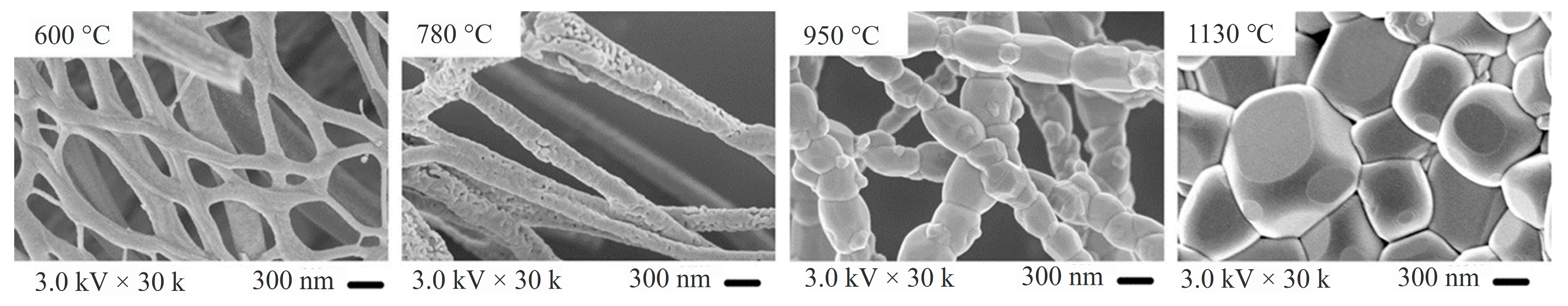
| CaCu3Ti4O12 | Cupric acetate, calcium nitrate, tetrabutyl Titanate, 2,2-bis(4-cyanatophenyl) isopropylidene | PVP | 600–1130 °C | Straight with beads | Dielectric | [30] |
| CaCu3Ti4O12 | Ti(C4H9O)4, Cu(NO3)2·3H2O, CuCl2, Ca(NO3)2·4H2O, CaCl2 | PVP | 900 °C–4 h | Straight | Fillers in dielectric | [31] |
| CdTiO3 | Cd(CH3COO)2·2H2O, TIP | PVA | 800 °C | Smooth and uniform surface | Removal of industrial pollutants and noxious wastes | [32] |
| Ce0.96Fe0.04O2 | Ce(NO3)3·6H2O, Fe(NO3)3·9H2O | PVP | 500, 600, 700, and 800 °C for 2 h | Straight | Magnetic applications | [33] |
| CexSm1−xO2 | Ce(NO3)3·6H2O, Sm(NO3)3·6H2O | PVP | 500 °C–2 h | Short fiber | Energy industrial applications | [34] |
| CoFe2O4 | Co(NO3)2·6H2O, Fe(NO3)3·9H2O | PVA | 300, 500 and 800·°C for 4 h | Straight | Magnetic recording device | [35] |
| CuCr2O4 | Cupric nitrate and Chromium acetate | PVP | 500–800 °C–2 h | Particles sintered after heat treatment | Catalysts | [36] |
| Cu2ZnSnS4 | Cu(CH3COO)2, Zn(CH3COO)2, SnCl2, thiourea | PVB | 150–550 °C, 1–48 h | Sintered after heat treatment, Laminated, Sintered particles | Photovoltaic cell | [37] |
| GdBaCo2O5+δ | Gd(NO3)3·6H2O, Ba(NO3)2, Co(NO3)2·6H2O | PVP | 600, 900 and 1000 °C for 5 h | Sintered particles | Solid oxide fuel cell | [38] |
| GeO2/SnO2 | Tin(II) chloride, germanium oxid | PVP | 500 °C–2 h | Straight | Lithium-ion batteries | [39] |
| HA | Ca(NO3)2·4H2O, P2O5 | PVP | 500–700 °C–0.5 h | Straight | Biomedical | [40] |
| Pd/Cu doped in CeO2 | Ce(NO3)3·6H2O, Pd(NO3)2·2H2O, Cu(NO3)2·2H2O | PVP | 550 °C | Straight and smooth | Water-Gas Shift (WGS) catalysis | [41] |
| LaCoO3 | La(NO3)3 6H2O, Co(NO3)2·6H2O | PVP | 200, 400, and 700 °C–2 h | Short fiber | Rechargeable Zn–air batteries | [42] |
| La2CuO4 | La(NO3)3·6H2O, Cu(NO3)2·2.5H2O | PVP | 600 °C for 5 h | Straight | Humidity sensor | [43] |
| LaMnO3 | La(NO3)3·6H2O, Mn(Ac)2·4H2O | PVP | 600 °C–3 h | Bend fibers after heat treatment | Sensors | [44] |
| La0.7Sr0.3MnO3 | LaN3O9·6H2O, Sr (NO3)2, Mn(NO3)2·4H2O | PVP | 500, 700, and 900 °C for 7 h | Continuous structures, packed particles | Magnetic properties | [45] |
| La2Zr2O7 | Basic zirconium carbonate, La(NO3)3·6H2O, LaCl3·6H2O, La(CH3COO)3·4H2O | PVA | 600 °C–2 h | Sintered particles to form a fiber | High temperature insulation applications | [46] |
| Li1.6Al0.6MnO4 doped Al | Lithium acetate, manganese nitrate and aluminum nitrate | PVA and PVP | 500,700,900 °C–2 h | Short and Straight fiber, relatively parallel | Lithium adsorption from polluted effluents | [47] |
| Ce doped Lu2SiO5 | Lu(NO3)3, Ce(NO3)3, Si(OC2H5)4, | PVB | 1000–1200 °C–4 h | Long straight fiber | Luminescent | [48] |
| Mullite | Al(C3H7O)3, Al(NO3)3·9H2O, Si(OC2H5)4 | Sol-Gel | 1000–1400 °C–2 h | Uniform-with beads | Reinforcement in ceramic matrix | [17] |
| Mullite | C9H21O3Al, (Al(NO3) 9H2O, SiC8H20O4 | PVB | 800–1400 °C–2 h | Straight | High temperature application, | [49] |
| Mn2O3 and Mn3O4 | Manganese nitrate 4-hydrat | PVA | 500, 700 and 1000 °C–1 h | Straight 3D porous random | Catalysis, ion exchange, molecular adsorption, biosensors, wastewater treatment and supercapacitors | [50] |
| Nb2O5 | Metallic niobium powder | PVP | 600–700 °C | Non-woven mat | Photocatalysis applications | [51] |
| NiO | Ni(NO3)2 | PVP | 400, 500 °C–1 h | Sintered particles, or lamellar after sintering | Gas sensor, Catalyst | [52] |
| NiO | Nickel (II) acetate tetrahydrate | SAN | 500–700 °C–2 h | Straight | Thermistor | [53] |
| Ni/Al2O3 | Ni(NO3)2·6H2O, Al(NO3)3·9H2O | PVP | 700 to 1000 °C | Straight and smooth after calcination | Catalyst | [54] |
| Pr0.4Sr0.6Co0.2Fe0.7Nb0.1O3−δ | Pr(NO3)3·6H2O, Sr(NO3)2, Fe(NO3)3. 9H2O, Co(NO3)3·6H2O, H3[NbO(C2O4)3] | PVP | 700 to 1000 °C–2 h | Short fibers | Solid oxide fuel cells | [55] |
| SiO2 | Accuglass | PVP | 400 °C several times | Bead shape fibers after heat treatment | Surface planarization | [56] |
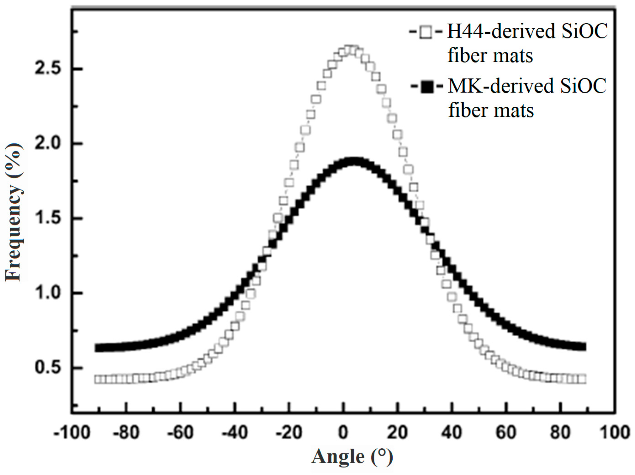
| Silicon oxycarbide (SiOC) | Silicone resins (MK and H44 resin) | PVP | 1000 °C–2 h | Straight and smooth | Mechanical application | [57] |
| Silicon oxycarbide (SiOC) doped Ag | Silver oxide or silver acetate, MK (polymethyl-silsesquioxane preceramic polymer) | PVP | 1000 °C–2 h | Straight, Ag inside the fibers | Antibacterial activity, Gas permeability | [58] |
| SiO2 doped Bi2MoO6 | (NH4)6Mo7O24·4H2O, Bi(NO3)3·5H2O | PVP | 500–750 °C–2 h | Broken short fibers | Photocatalytic | [59] |
| SnO2 | Tin acetate | PVAc | 450 °C, 0.5 h | Regular fibrillar structure | Gas sensing | [60] |
| SnO2 doped Al | SnCl2·2H2O, Al(NO3)3·9H2O | PVP | 600 °C–5 h | Bead shape fibers sintered after heat treatment | Hydrogen sensor | [61] |
| SnO2 doped Ce | SnCl2·2H2O, Ce(NO3)3·6H2O | PVP | 600 °C–5 h | Hollow fibers | Ethanol gas sensor | [62] |
| SnO2 doped Eu | SnCl2·2H2O, Eu(NO3)3·6H2O | PVP | 600 °C–5 h | Straight and smooth after calcination | Acetone sensor | [63] |
| Sm2O3 | Samarium carbonate | PVA | 1000 °C–2 h | Sintered particles forming a fiber | Optical film, insulator | [64] |
| SrFe12O19 | Sr(NO3)2, Fe(NO3)3·9H2O | PVP | 750 °C–1.5 h | Short and relatively dense after heat treatment | Photocatalytic adsorption | [65] |
| TiO2 | Butyl titanate | PVP | 550 °C–2 h | Smooth | Photocatalyst | [66] |
| TiO2 | Titanium (IV) n-butoxide (TNBT) | PVP | 500 °C–6 h | Depend on humidity varied from short to long fibers | Photocatalyst | [67] |
| TiO2 | Ti(OiPr)4 | Sol-Gel | 500 °C–3 h | Short fibers | Electrochemical detection | [68] |
| WO3 | WCl6, PVP | 300–500 °C–1 h | Short fiber | NO2 gas responses | [69] | |
| WO3 | (NH4)6[H2W12O40] nH2O | PVP | 500, 550, 600 °C–1 h | Short fiber with sintered NPs | N.A. | [70] |
| Yb2O3 | Ytterbium chloride | CA | 550 °C to 850 °C–2 h | Particle and agglomerate before and after calcination | fiber amplifiers, fiber optic technologies and lasers | [71] |
| ZnO | Zinc acetate dehydrate | PVA | 500 and 700 °C–4 h | Straight, Fluffy surface | Biosensors | [72] |
| ZnO | Zinc acetate dehydrate | PVA | 500 °C–2 h | Straight, Random | Low frequency AC electric fields | [21] |
| ZnO | Zinc nitrate hexahydrate | PVP | 500 °C–3 h | Straight | Explosive nitro-compounds sensor | [73] |
| ZnO/BaO | Zinc acetate dehydrate barium acetate extra pure | PVA | 850 °C–8 h | Straight | Electrical and non-linear optical | [74] |
| ZnO/SnO2 | Zn(NO3)2·6H2O, SnCl4·5H2O | PAN | 700–900 °C–3 h | Rough surface | Lithium-ion anode | [75] |
| ZnO doped Mg | Zinc acetate, magnesium acetate | PVA | 300–600 °C–3 h | Sintered particles | Semiconductor | [76] |
| ZnO doped Cu | Zinc acetate, copper acetate | PVP | 450 °C–3 h | Straight | Thermal and electrical conductivity, and optical properties | [77] |
| ZrC | Polyzirconoxane (PZO) | PAN | 1400 °C–2 h | Core–shell, homogeneous | Ultra high temperature ceramics | [78] |
| ZrO2 | Zirconium n-propoxide | PVA | 600 to 1050 °C–4 h | Non-woven fibers | Thermal barrier coatings | [79] |
| ZrO2 (YSZ) | Zirconium oxychloride, Yttrium trinitrate hexahydrate | PVP | 500–1500 °C | Bead shape fibers after heat treatment | Catalytic activity | [80] |
| ZrO2 (8YSZ) | ZrOCl2·8H2O, Y2O3 | PVP | 600–1400 °C–12 h | Hollow fibers | Catalytic combustion | [81] |
| Ceramic | Polymer Type | Application | Ref |
|---|---|---|---|
| Graphene (G) | PANI, PS, DMF | Electrochemical sensor | [84] |
| TiO2 | PVP | Photo catalyst | [85] |
| Al2O3 | PVDF-CTFE | Lithium-ion batteries | [86] |
| Al2O3 | PLA | Biomedical Application | [87] |
| ZrO2/Y2O3 | PAN | Shielding in electronic device | [88] |
| HAp | PHBV | Tissue engineering | [89] |
| CNT | PVDF | Strain sensors | [90] |
| SiO2, Al2O3 or BaTiO3 | P(VdF-HFP) | Lithium-ion batteries | [91] |
| BaTiO3 | PVDF | Piezoelectric materials Energy harvesting | [92,93] |
| Boehmite (AlOOH) | PA6, PCL | Removal of heavy metal ions | [94] |
| CuO | PU | Electrical application | [95] |
| Sepiolite (Si12O30Mg8(OH)4–(H2O)4.8H2O) | PVB | Mechanical integrity in real applications | [96] |
© 2017 by the authors. Licensee MDPI, Basel, Switzerland. This article is an open access article distributed under the terms and conditions of the Creative Commons Attribution (CC BY) license (http://creativecommons.org/licenses/by/4.0/).
Share and Cite
Esfahani, H.; Jose, R.; Ramakrishna, S. Electrospun Ceramic Nanofiber Mats Today: Synthesis, Properties, and Applications. Materials 2017, 10, 1238. https://doi.org/10.3390/ma10111238
Esfahani H, Jose R, Ramakrishna S. Electrospun Ceramic Nanofiber Mats Today: Synthesis, Properties, and Applications. Materials. 2017; 10(11):1238. https://doi.org/10.3390/ma10111238
Chicago/Turabian StyleEsfahani, Hamid, Rajan Jose, and Seeram Ramakrishna. 2017. "Electrospun Ceramic Nanofiber Mats Today: Synthesis, Properties, and Applications" Materials 10, no. 11: 1238. https://doi.org/10.3390/ma10111238
APA StyleEsfahani, H., Jose, R., & Ramakrishna, S. (2017). Electrospun Ceramic Nanofiber Mats Today: Synthesis, Properties, and Applications. Materials, 10(11), 1238. https://doi.org/10.3390/ma10111238