1. Introduction
One of the main recurring problems within wind turbine blades is fatigue of the blade, especially as the magnitude of the blade size is increasing. The blades are subjected to a highly irregular loading condition caused by turbulent wind flow, gravity, and inertial loading during accelerating or decelerating of the turbine. A wind turbine blade is predominantly loaded in the flapwise and edgewise directions. During operation, the source of flapwise loads are mainly aerodynamic, while the edgewise loads are mainly caused by gravity. The aerodynamic loading is at maximum when the blade position is at 12 O’clock due to higher wind velocity from wind shear, and a minimum when the blade is at 6 O’clock when the blade passes through stagnant air in front of the turbine tower. A modern wind turbine is designed to last 20–30 years almost unattended; hence, a comprehensive testing of the blade is mandatory. Details of the blade testing, inspecting and monitoring procedures can be found in [
1,
2].
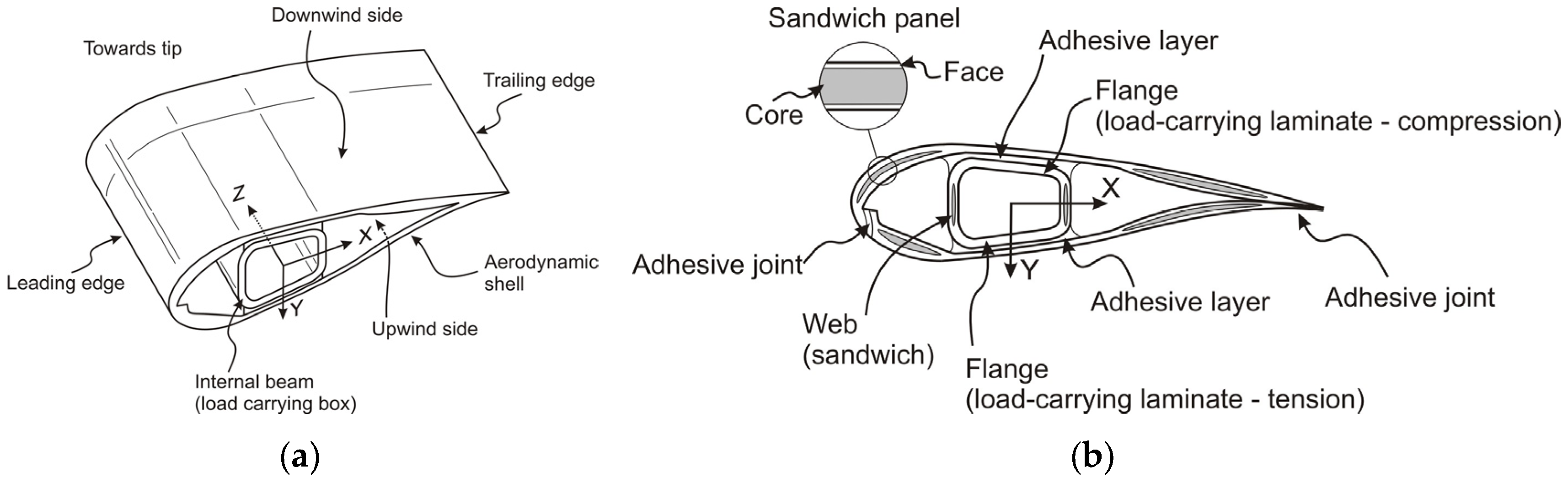
The flapwise loads are carried by the main spar (or girders) while edgewise loads are taken partially by spar and partially, if present, by reinforcement in the leading and trailing edges. Shear webs are located between the two spar caps and provide shear strength to the blade. They are usually made from sandwich structure with bi-axial fibre laminate skins and a central core. The rest of the blade is usually constructed from multi-axial skin material and sandwich structure from glass fibre reinforced polymer (GFRP) composite layers, with a core from foam or balsa wood, ensuring low mass, resistance to torsion and buckling. Characterisation of GFRP materials prior to using in the blade is necessary and the procedure for determining delamination toughness and fatigue performance of GFRP have been reported elsewhere [
3,
4,
5].
As part of the certification procedure, all wind turbine blades are subjected to static, fatigue and failure tests in order to ensure that the produced wind turbine blade fulfill the actual design requirements. Blade manufactures are required to carry out static and fatigue tests of full-scale blades prior to their deployment for commercial use according to international standards [
6,
7,
8,
9] and guidelines [
10,
11]. The static test applies the appropriate extreme load in all directions, i.e. leading edge, trailing edge, suction side and pressure side. The whole static test is then repeated after the fatigue test to ensure that the blade can handle extreme loads after it has been subjected to high cyclic loading. For application of new materials, or other significant changes in the structural design of the blade, a failure test (also called crash test) may be necessary in addition to the static and fatigue tests. After a crash test the blade is cut open at the point of fracture, and the fracture surfaces are examined in detail to find out the root cause of failure. The design may be revised after the forensic analysis of the fracture surfaces.
Yang et al. [
12] have done blade crash testing under flapwise loading on a 40 m long blade made from E-glass/epoxy composite materials. They evaluated the structural response of the blade during loading and after crash they correlated experimental data with numerical modelling. They showed the blade sections subjected to bending moments can suffer a non-linearity in their bending response and may crush from the rotated compressive or tensile forces due to the curvature that arises from bending. Kühlmeier [
13] showed an interlaminar shear failure originated from local bending in the shell due to an initial geometric imperfection could trigger a progressive collapse of the wind turbine blade section.
Lee and Park [
14] tested a 48.3 m wind turbine blade to find the residual strength of the blade subjected to initial static and then fatigue tests. In the positive flapwise direction (from the pressure-side shell to the suction-side shell), the blade was able to sustain the most severe load, but when a static load was applied in the opposite direction the blade collapsed when subjected to 70% of the maximum target load, equivalent to 50% of the most severe load in the positive flapwise direction. Based on the test results and the fracture patterns at the blade’s broken section, they suggested a modified laminate lay-up from (±45/0/core/±45/0) to (±45/0/core/0/±45). Of course this modification makes the laminate symmetric and as a result the coupling stiffness matrix of the laminate,
B matrix, becomes zero and extension and bending becomes decoupled.
Jensen et al. [
15] tested a 34 m wind turbine blade until its structural collapse. The reported failure mechanism was debonding of the outer shell skin followed by delamination buckling. It was noted that the non-linear distortion was caused by the crushing pressure derived from the Brazier effect. The Brazier pressure, where the flexural starts to decrease due to ovalisation of the blade structure, has a significant impact on the design of new blades. They optimized a box girder and showed the importance of including Brazier pressure in the design process for wind turbine blades.
For very long blades, it has been found that buckling failure becomes more important than tip deflection and even fatigue [
13]. In blades for safety against buckling a 1.634 safety factor is recommended, meaning that the structure must be capable of withstanding 1.634 times the worst case buckling condition. Cox and Echtermeyer [
16] studied the effect of changing the fibre orientations of the less stiff, off-axis glass fibre plies on increasing the critical buckling load of a 70 m carbon/glass hybrid wind turbine blade from nonlinear finite element analysis. They showed the orientation of the stability plies influences the onset of the Brazier effect, which in turn affected blade stability and buckling failure location. They achieved a maximum increase of 8% in critical buckling load by changing the orientation of the stability plies from ±45° as specified in the reference blade to ±70° while both blade weight and laminate thickness remained constant.
Blade root failure can result in the blade being pulled out from its hub during operation. Lee et al. [
17] reported delamination failure at the blade root during full-scale fatigue testing of a 3 MW wind turbine blade with length and weight of 56 m and 14.5 ton, respectively. They noticed that the bumping motions of the blade shell redistribute the load at the blade root, resulting in the alleviation of stresses in some locations and the increase of stresses in other locations. They carried out finite element analysis, and showed that in a slender and large wind turbine blade, the actual load distribution at the root is very different from that calculated using assumptions that the blade root has enough stiffness to be modelled as a bending of a hollow circular cylinder.
The fatigue life of the blade can be improved by embedding secondary nanoreinforcements in the polymer matrix. Mishnaevsky and Dai [
18] used computational modelling and showed that secondary nanoreinforcement can drastically increase the fatigue lifetime of composites. Many other researchers have shown experimentally that the toughness of the resin can be substantially improved by adding nanoparticles to the polymer matrix [
19]. Recently by addition of 0.25 wt % of plasma functionalised graphene nanoparticles to epoxy, the fracture toughness has been increased by more than 50% [
20]. Using these new advanced resins will improve a broad range of other physical and mechanical properties of the fibre reinforced composite as well at relatively low cost, a promising material for improving the fatigue damage tolerance of wind turbine blades.
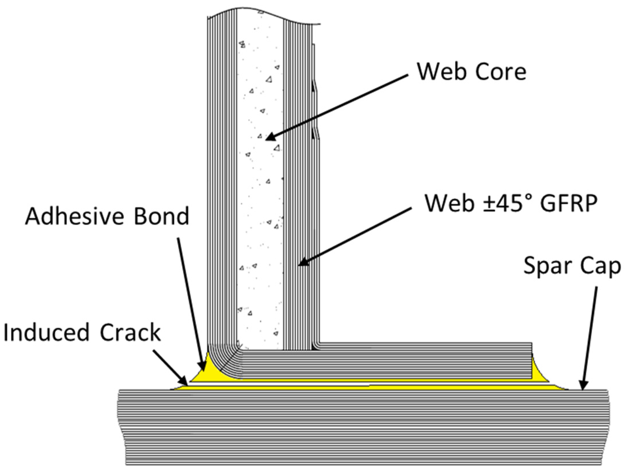
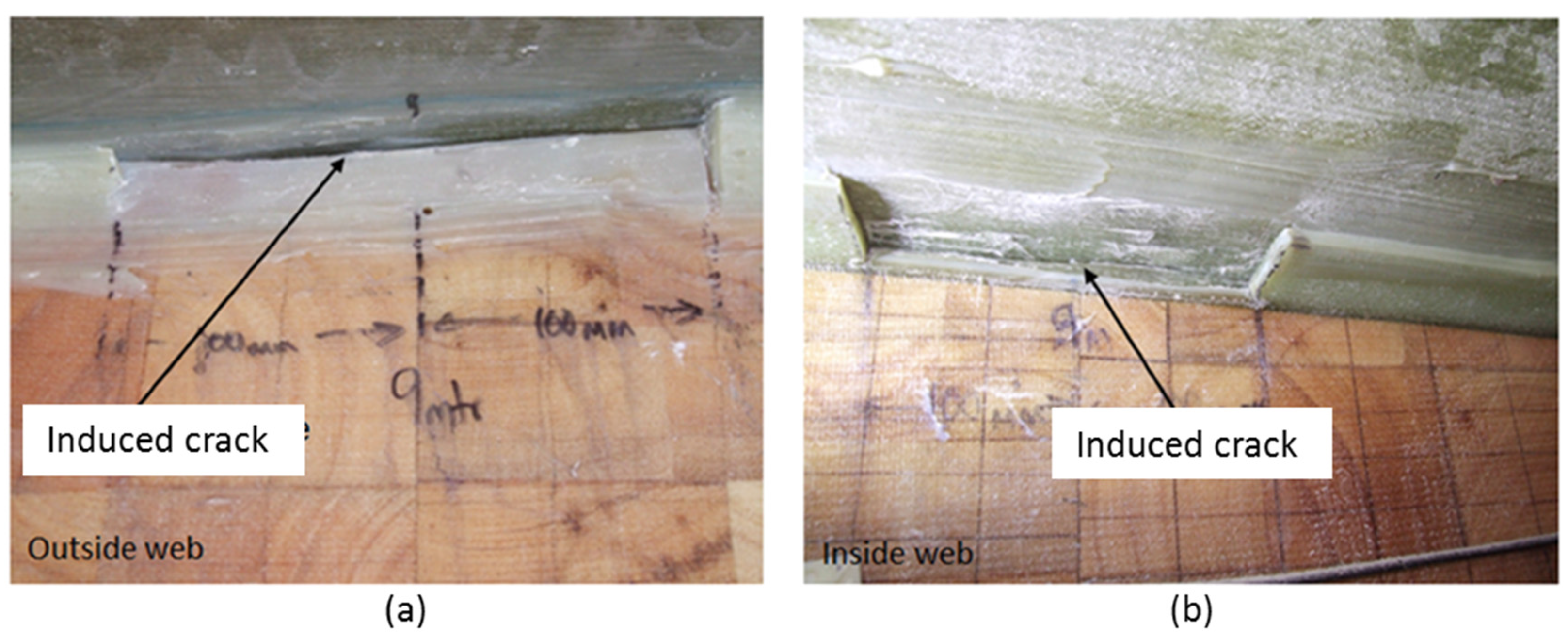
In this paper, a step-by-step full-scale fatigue test of a wind turbine blade is discussed. After the fatigue testing of as received wind turbine blade, the sensitivity of the blade to damage, by manually debonding the shear web from spar cap as shown in
Figure 1, has been investigated. The steps of the testing included modal analysis, static, and fatigue testing of a 45.7 m blade in three states of the blade: (i) as received blade (ii) when a crack of 200 mm was introduced between the web and the spar cap and (iii) when the crack was extended to 1000 mm length. As no design data for the blade was available, the location of the crack was chosen to be at a point on the blade which is usually structurally challenging (around max chord) and where the bond line was relatively easy to access.
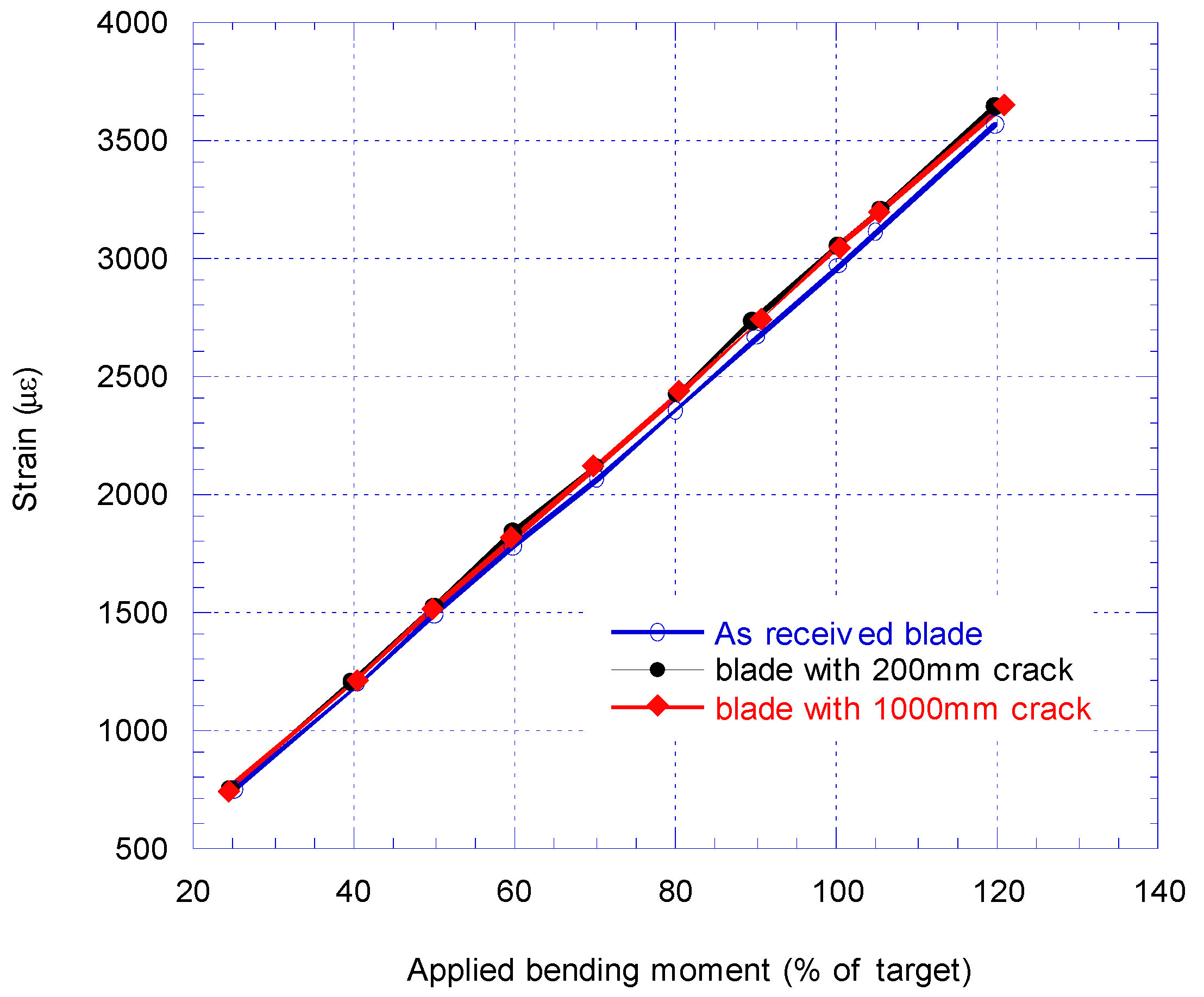
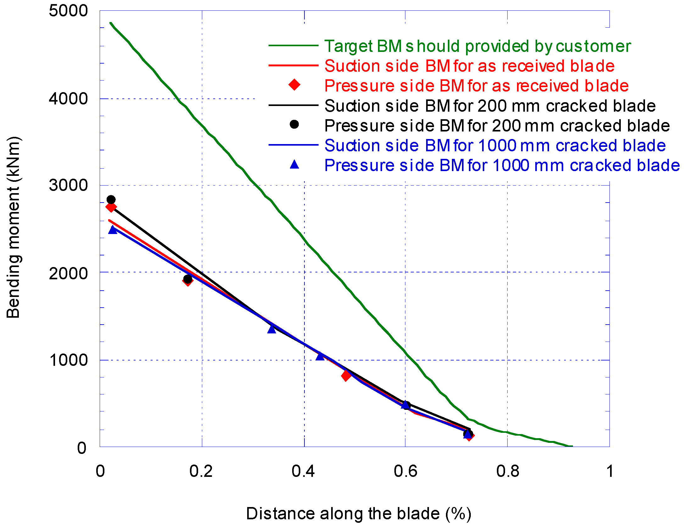
The calibration pull-tests for all three states of the blade were performed to obtain the strain-bending moment (BM) relationship of the blade according to the target BM which the blade is expected to experience in its service life. The data was used for applying appropriate loads in the fatigue tests. Then the blade natural frequencies in both the flapwise and edgewise directions over a frequency domain range were found by modal testing using hammer impact for all three states of the blade. The IEC 61400-23 standard [
6] has then been followed for full-scale blade fatigue testing. Finally, the states of the crack and accompanying damage for all states of the blade have been identified.
5. Fatigue Tests
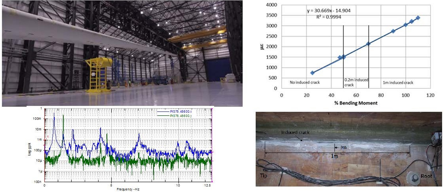
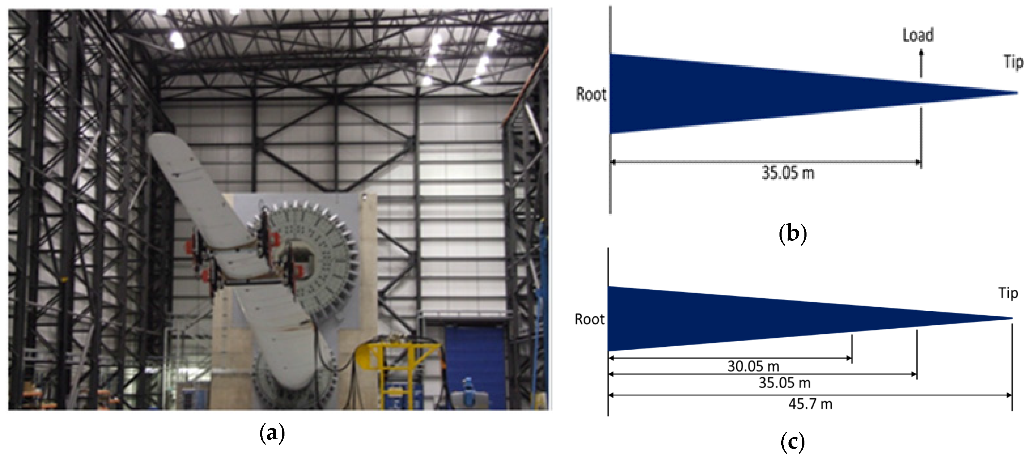
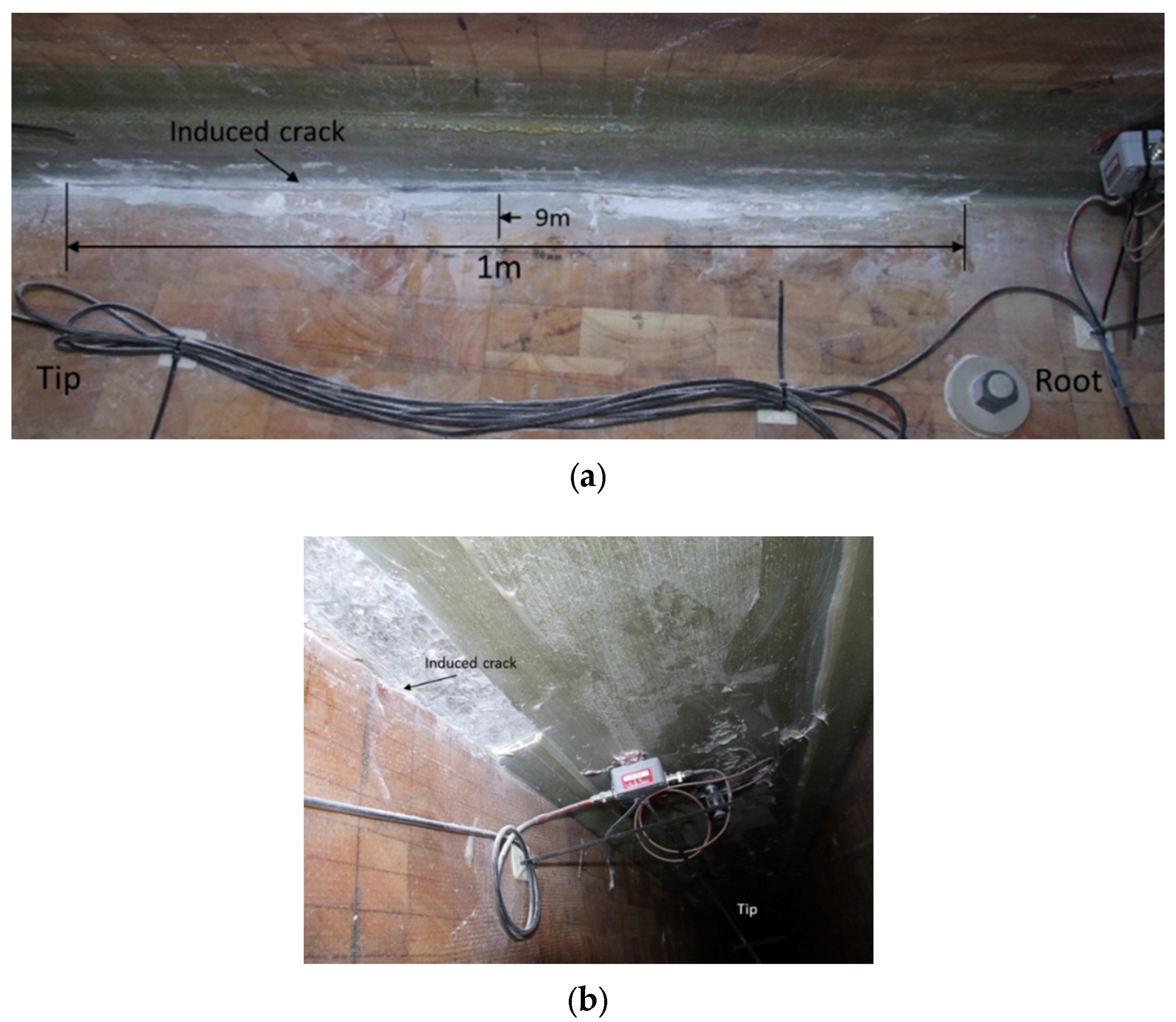
The blade was excited by two saddles sitting at 30.05 m and 35.05 m from the root of the blade as shown in
Figure 3. The saddles masses oscillated at just below the determined first natural frequency of the blade to excite the blade to reach to the specific strain at a preselected strain gauge SG2 located at 8 m from the root on pressure side in longitudinal direction.
5.1. Fatigue Test Results before Crack Insertion
The test conditions and fatigue test results for as received blade are summarised in
Table 3 where the target strain at SG2 is set at 1478 με, reaching 2500 kNm, 50% of target BM at the root as predicted from the calibration pull-test described in
Section 4.1. After 5241 cycles a visual inspection of the blade was performed and three new cracks were detected. The first cracks appeared at 34 m in the TE where a 450 mm adhesive joint failure occurred. The second crack of a length of 300 mm occurred at the adhesive joint in the TE at 31 m from the root. The third crack formed at the adhesive joint in the LE at 28.36 m.
In the test, the acoustic emission (AE) sensors recognised damage around the same regions as they were found by visual inspection. After 58,665 cycles the blade has been inspected visually and no new crack was found, nor did the existing crack propagate. The fatigue test on as received blade was stopped after 65,217 cycles and at the end of the test, the original cracks had not propagated further. It is likely that an edgewise test rather than a flapwise test would have been more effective at growing the crack because the spar cap adhesive bond would experience greater shear stresses during an edgewise test.
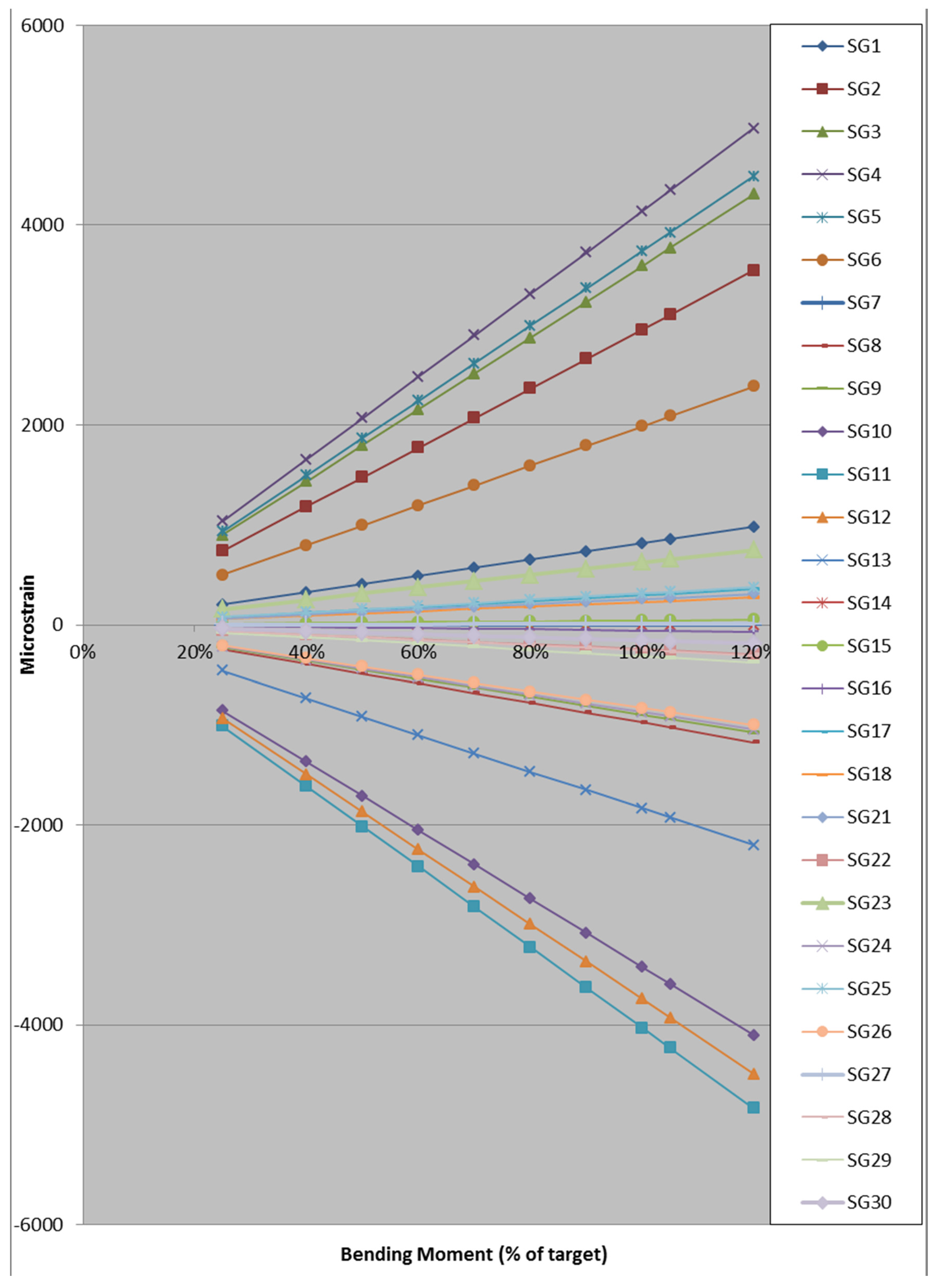
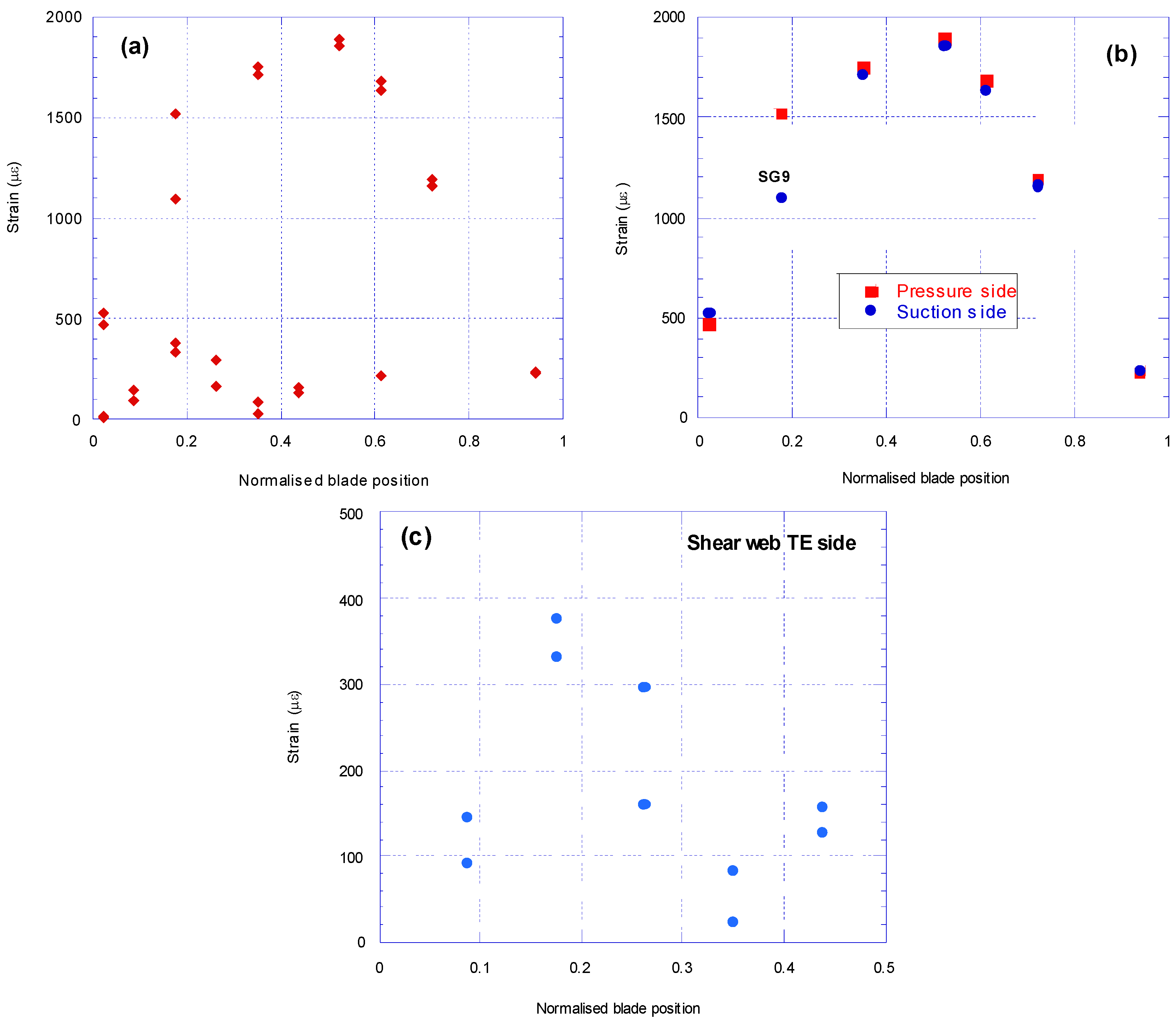
The strains at the first cycle along the as received blade from 30 strain gauges are shown in
Figure 12a. The highest strains are experienced between 35% and 65% of the blade length from the blade root.
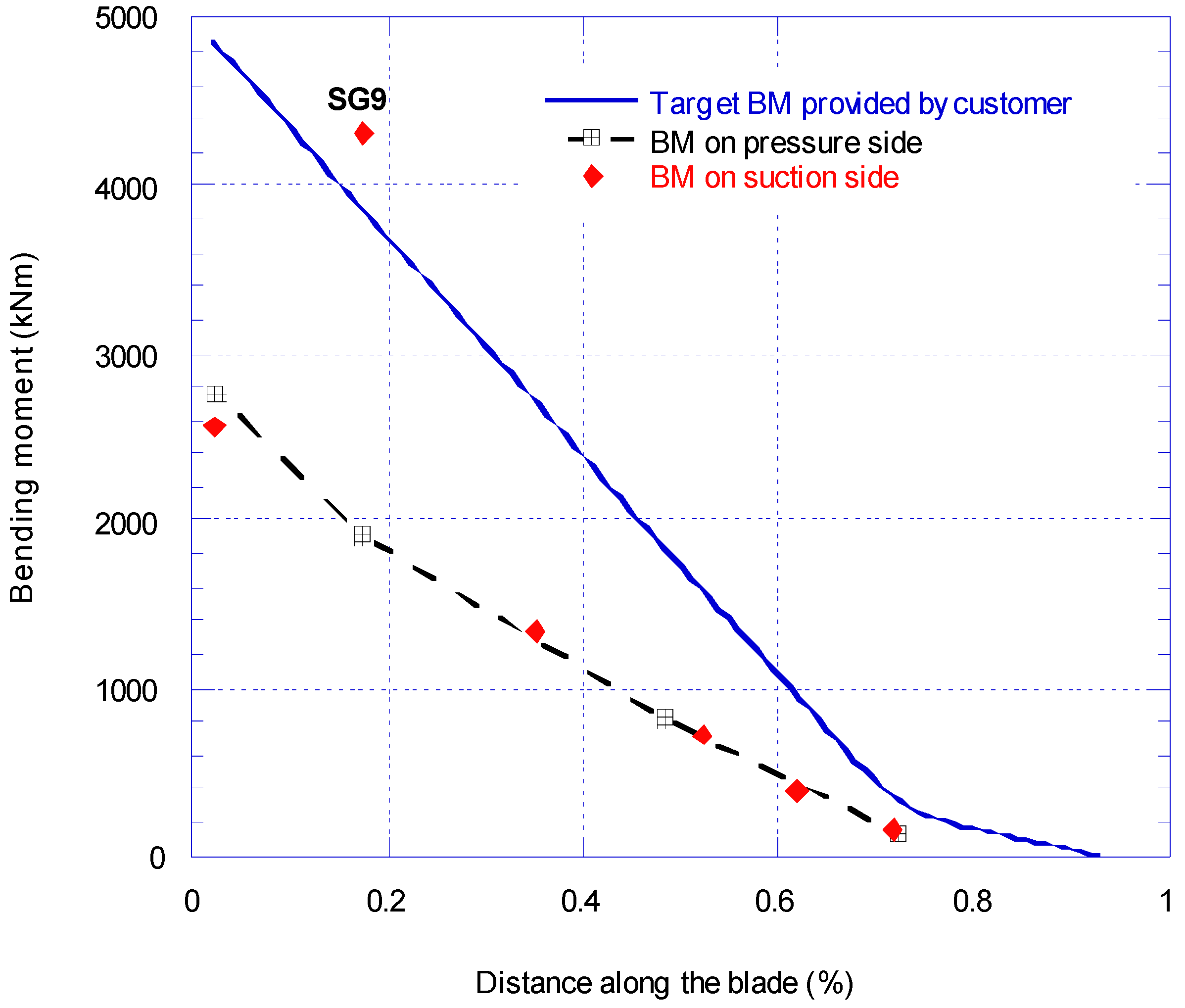
Strain gauge results on the skin of the pressure and suction sides at the first cycle are shown in
Figure 12(b), where the strain along the blade varies between 236 με and 1891 με. The highest strain on shell skin is at 52% of the overall length. The results are almost identical on the pressure side and suction side, apart at the 17% blade location where the pressure side shows a reading of 423 με more than the suction side. This indicated that the strain gauge SG9 on the pressure side was faulty and therefore its reading was discarded.
Strain gauges SG21 to SG30 are attached to the shear web on TE side at ±45° and located from 4 m to 20 m from the root. The readings from these gauges at the first cycle are shown in
Figure 12c. The strain along the first half of the blade length from the root varies between 24.5 με and 378 με. In flapwise fatigue, the maximum strain readings in the shear web occurred at SG23 and SG24 attached to the shear web, located at 17.5% of the blade length from the root.
5.2. Fatigue Test Results for Blade with 200 mm Crack
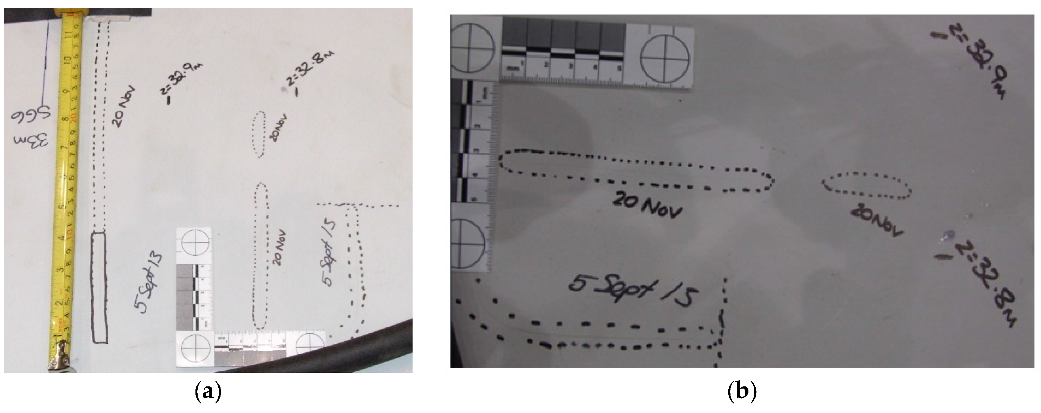
The test conditions and results for the blade with a 200 mm crack are shown in A pre-existing crack at around 32.96 m had extended by 190 mm in the middle of the blade as shown in
Figure 13a with the overview image of the two cracks found.
Figure 13b shows a close inspection of the new cracks found at about 32.83 m from the blade root which propagated for 110 mm and 40 mm on the middle cross section at this point. The next visual inspection was carried out after 39,934 cycles, where the applied BM value had been increased to 70% of the maximum target BM. The visual inspection showed an existing crack at about 32.96 m propagated 15 mm along the blade longitudinal direction at the TE midpoint. Finally, a visual inspection was made after 62,110 cycles and no further crack formation or propagation was observed and the induced crack stayed unchanged at its original length.
Table 4. Initially, a 2500 kNm bending moment at the root was applied which resulted in 1523 με at SG2. The strain at this location had increased from 1478 με before the insertion of crack, showing a 3% increase. A visual inspection was performed after 8063 cycles to check if any existing cracks had propagated or new ones formed. No changes to the existing cracks or to the 200 mm crack at 9 m distance were observed. Later on the visual inspection was repeated after 26,851 cycles. A pre-existing crack at around 32.96 m had extended by 190 mm in the middle of the blade as shown in
Figure 13a with the overview image of the two cracks found.
Figure 13b shows a close inspection of the new cracks found at about 32.83 m from the blade root which propagated for 110 mm and 40 mm on the middle cross section at this point. The next visual inspection was carried out after 39,934 cycles, where the applied BM value had been increased to 70% of the maximum target BM. The visual inspection showed an existing crack at about 32.96 m propagated 15 mm along the blade longitudinal direction at the TE midpoint. Finally, a visual inspection was made after 62,110 cycles and no further crack formation or propagation was observed and the induced crack stayed unchanged at its original length.
5.3. Fatigue Test Results for Blade after Extending the Crack to 1000 mm
The test conditions and results for the blade after extending the inserted crack to 1000 mm are shown in
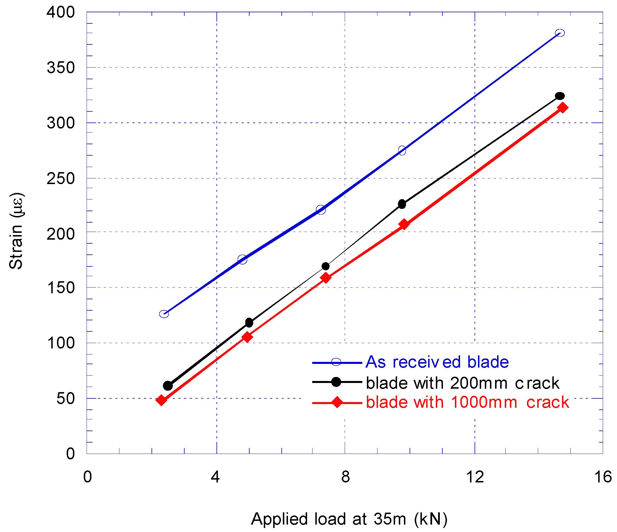
Table 5. Initially 3500 kNm bending moment equivalent to 70% of target BM were applied at the root which resulted in 2135 με at SG2. The strain at this location remained nearly unchanged close to 2132 με before the crack extended from 200 mm to 1000 mm. Visual inspections of the blade were performed after 3967; 16,781 and 18,764 cycles to check the state of the cracks in the blade. No changes to the existing cracks or to the induced crack at 9 m were detected.
The load was then increased to 90%, 100%, 105% and 110% of the blades estimated target BM value. For these tests the blade first mode natural frequency was obtained using ORE software rather than doing modal tests to save time.
As mentioned earlier, for this state of the blade mass has been added to the saddles to reduce the saddle stroke amplitude. The mass on the saddle at 30.05 m was increased from 150 kg to 200 kg and at 35.05 m was increased from 75 kg to 100 kg on both sides of the saddle, to achieve 70% of the nominal target BM. At 90% of the nominal BM loading, the mass at 30.05 m was increased to 325 kg and at 35.05 m increased to 150 kg on both sides of the saddle. Finally, at 100% and 110% of the nominal BM loading, the mass at 30.05 m was increased to 400 kg and at 35.05 m increased to 200 kg on both sides of the saddle.
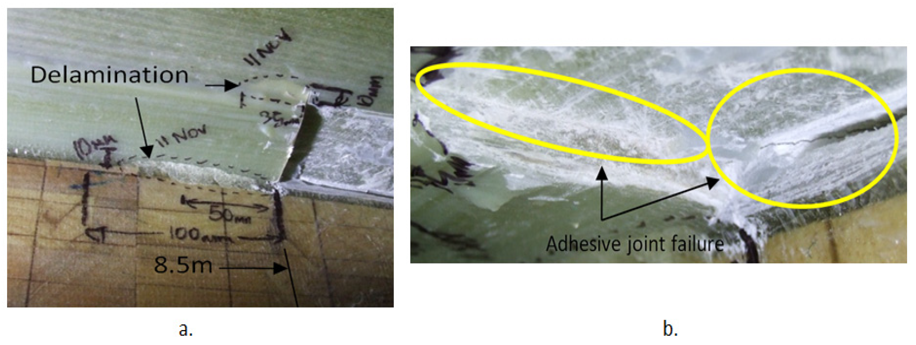
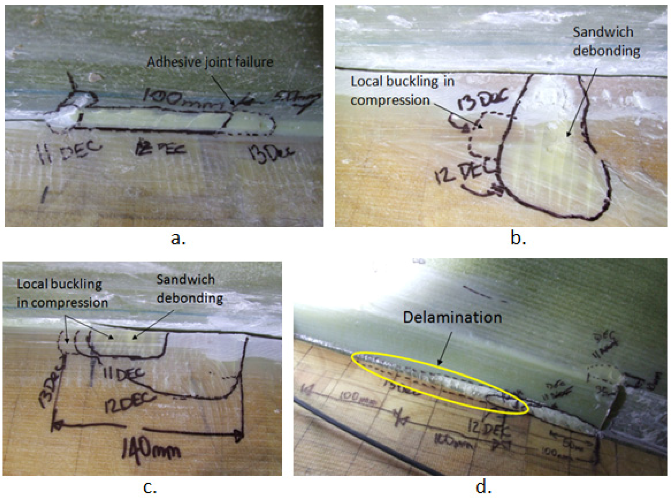
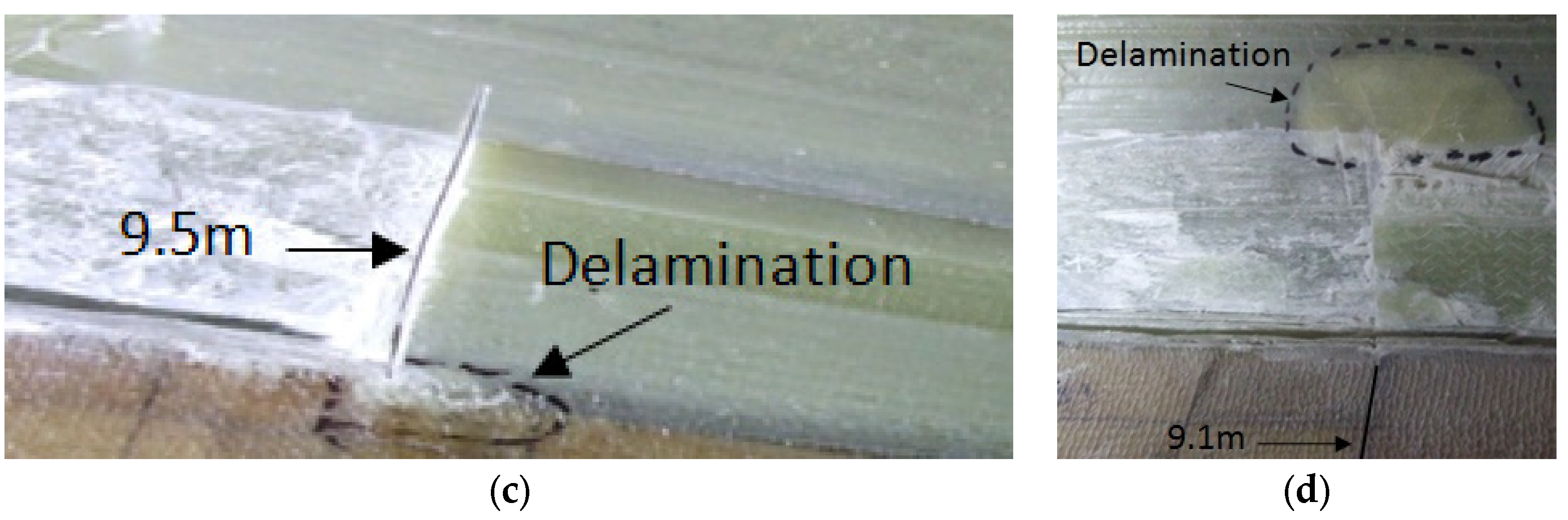
A visual inspection of the blade after 34,776 cycles showed a number of cracks was formed around the 1000 mm extended crack. Inside the web box at 8.5 m from the root, two delaminated areas each at 10 mm in width were detected. The delamination connected to the web had a delamination length of 83 mm and the delamination furthest away from the web had a length of 35 mm as shown in
Figure 14a. At 8.5 m, the induced crack through the adhesive joint had propagated from its corner and extended through the plies causing delamination on the web lip, indicating that the crack plane has been deviated from its original path; see
Figure 14b. At 9.5 m from the blade root delamination had occurred at the corner of the 1000 mm crack as shown in
Figure 14c.
Figure 14d shows delamination at 9.1 m at the location of the corner of the 200 mm crack. The fact that the crack bridged across from the unreinforced adhesive to shear web laminate is interesting, and is probably a result of the complex mode II loading that would be induced by a flapwise test in this region. It is also possible that when cutting the crack the blade had travelled into reinforced material as well as through the adhesive, which would make the bridging more likely to occur.
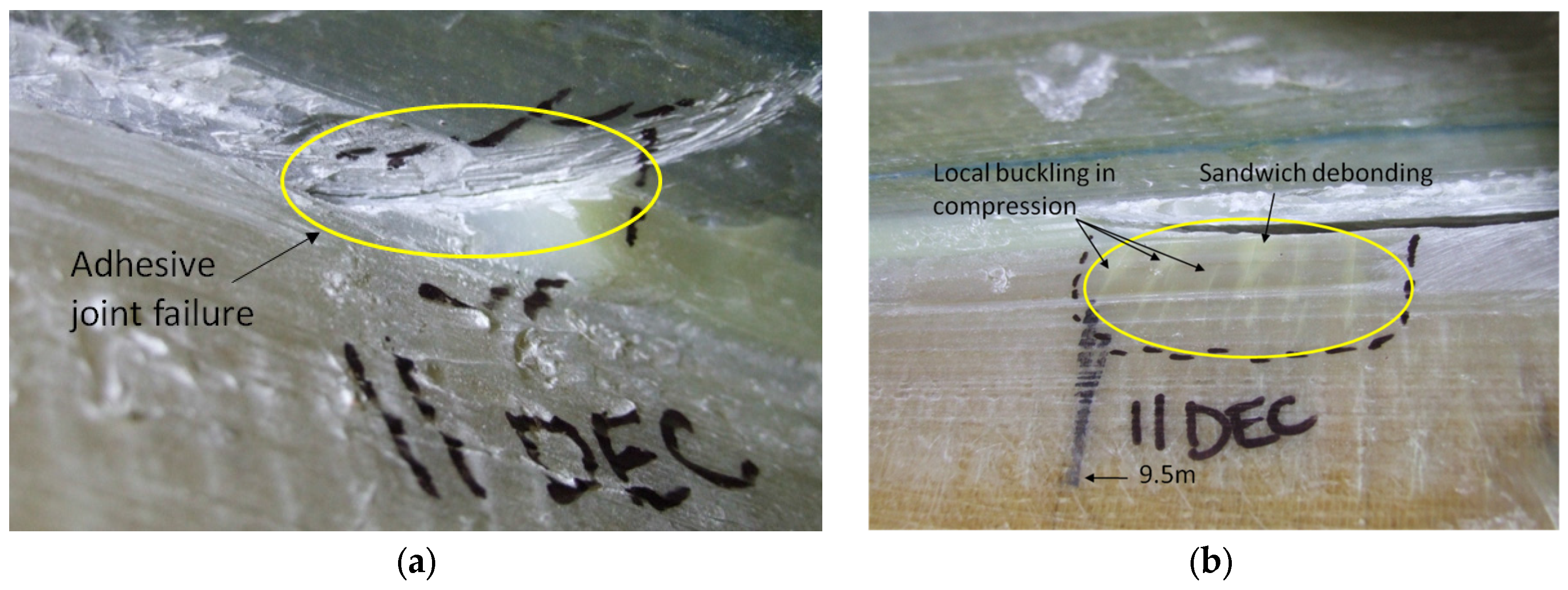
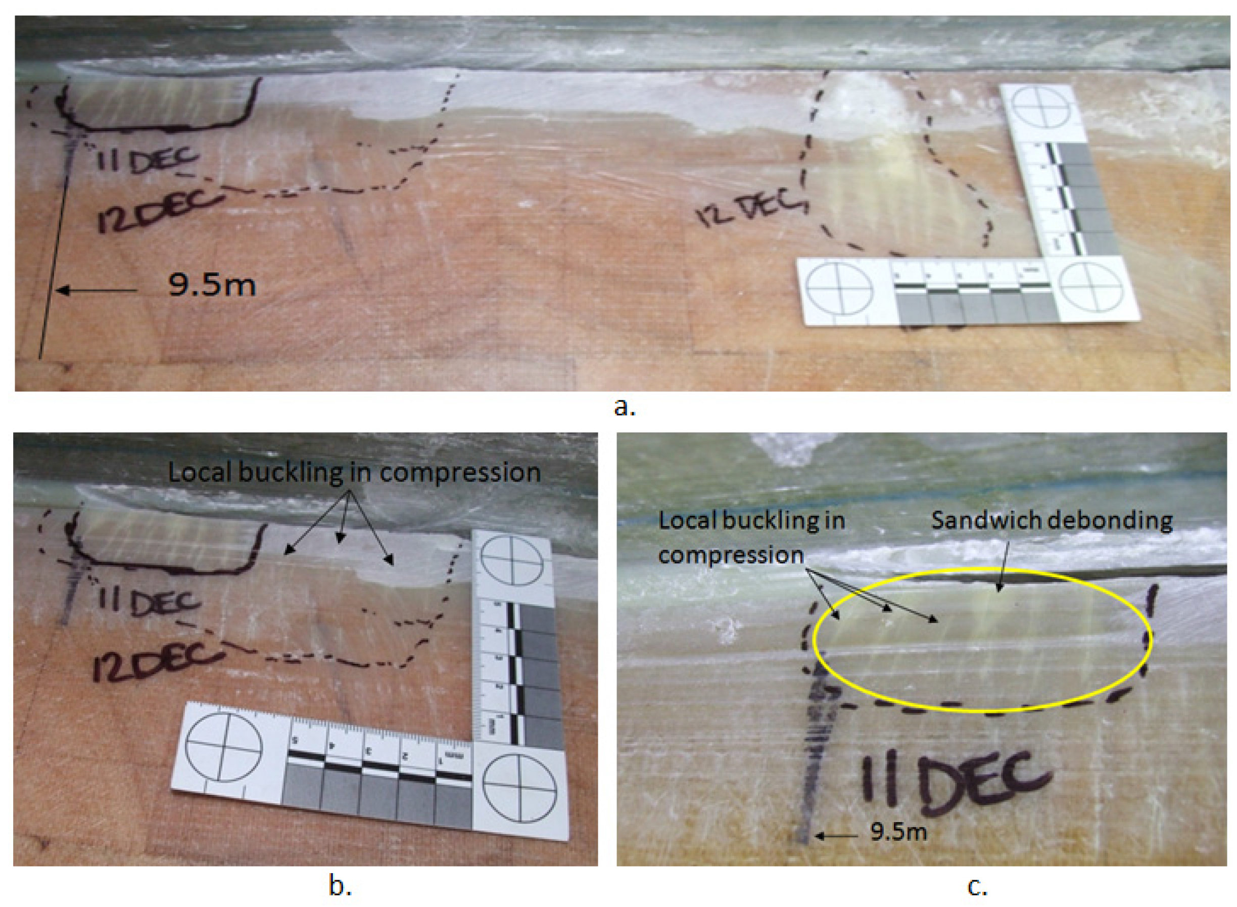
The adhesive joint had debonded outside the web box at 8.5 m as shown in
Figure 15a indicating that the crack had propagated all the way through the web. At 9.5 m the blade experienced multiple local buckling under compression, and debonding in the sandwich propagated into the web, as shown in
Figure 15b.
A visual inspection of the blade after 47,206 cycles showed a number of further damages around the 1000 mm extended crack. At 8.5 m inside the web box, there were two areas of delamination each 10 mm in width. The delamination connected to the web, where the delamination length had extended by 25 mm. At 8.9 m inside the web box, delamination had occurred at the corner of the original 200 mm induced crack. Inside the web box at 9.5 m, delamination had extended from the corner of the 1000 crack to the lip of the web.
Figure 16a shows outside the web box at 9.5 m with an overview of the damaged areas. The blade experienced multiple local buckling under compression, and sandwich debonding going into the web.
Figure 16b is the magnified view of the damaged area at 9.5 m and
Figure 16c shows the magnified view of the damaged area at 9.3 m. The crack had also propagated 100 mm in the adhesive joint at 8.5 m.
A visual inspection of the blade after 56,762 cycles showed that many of the cracks had extended along the web within the 1000 mm crack area as illustrated in
Figure 17. At 9.5 m inside the web some delamination had also begun to occur.
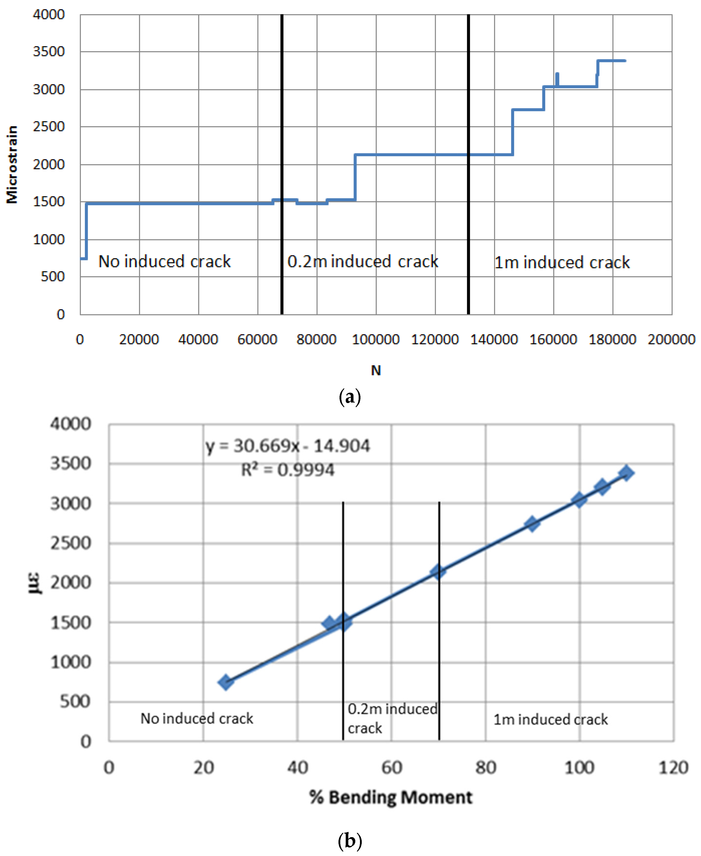
The variation of SG2 strain versus number of cycles and percentage of applied BM experienced by the blade at all stages of the fatigue testing for three states of the blade are shown in
Figure 18. The figure shows that no nonlinearity occurred during the entire testing cycles, and that the various damages created during the fatigue tests had not yet caused any noticeable deterioration to the structural stiffness of the blade.
6. Conclusions
The blades are one of the most critical components of the wind turbine. The structural integrity of the whole wind turbine depends on the blade, and therefore they have to be tested in order to ensure that the blade can withstand both the ultimate loads and the fatigue loads to which the blade will be subjected during its entire service life. Testing of the wind turbine blades in static and fatigue loading reveal any possible weakness in the design, materials and the manufacturing processes. Removing the weakness will save both the expensive cost of maintenance or replacement.
In this paper, all required steps for full-scale fatigue testing of a 47.5 m blade have been discussed. The starting point was acquiring the required information for fatigue from the calibration pull-tests. From this test the magnitude of strain for monitoring the target BM at the root of the blade in fatigue testing has been identified. These tests were performed in three stages of blade: (i) as received blade; (ii) when a 200 mm crack was introduced and (iii) when the crack extended to 1000 mm. From the calibration pull-tests the strain-bending moment relationship of the blade has been identified according to the target BM which the blade expected to experience in its service life. These data were used for monitoring the applied bending moment in the fatigue tests.
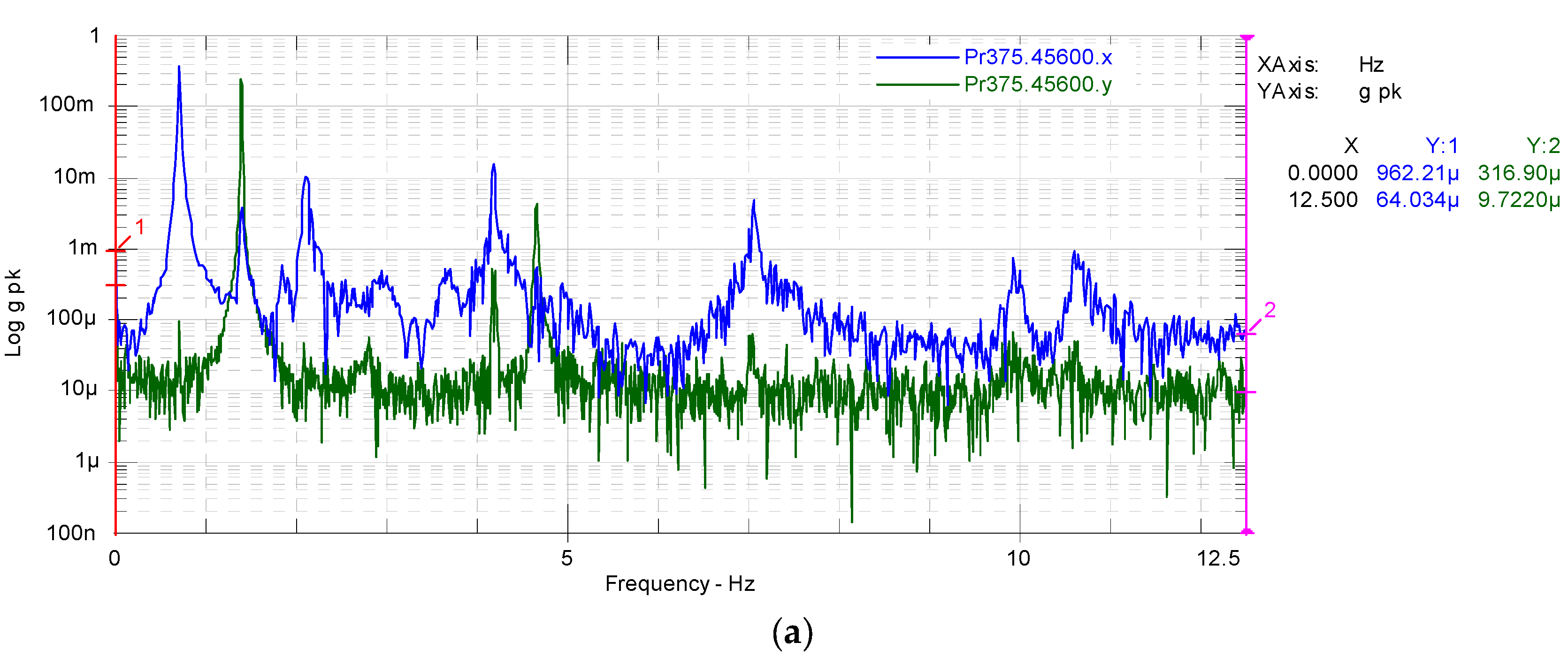
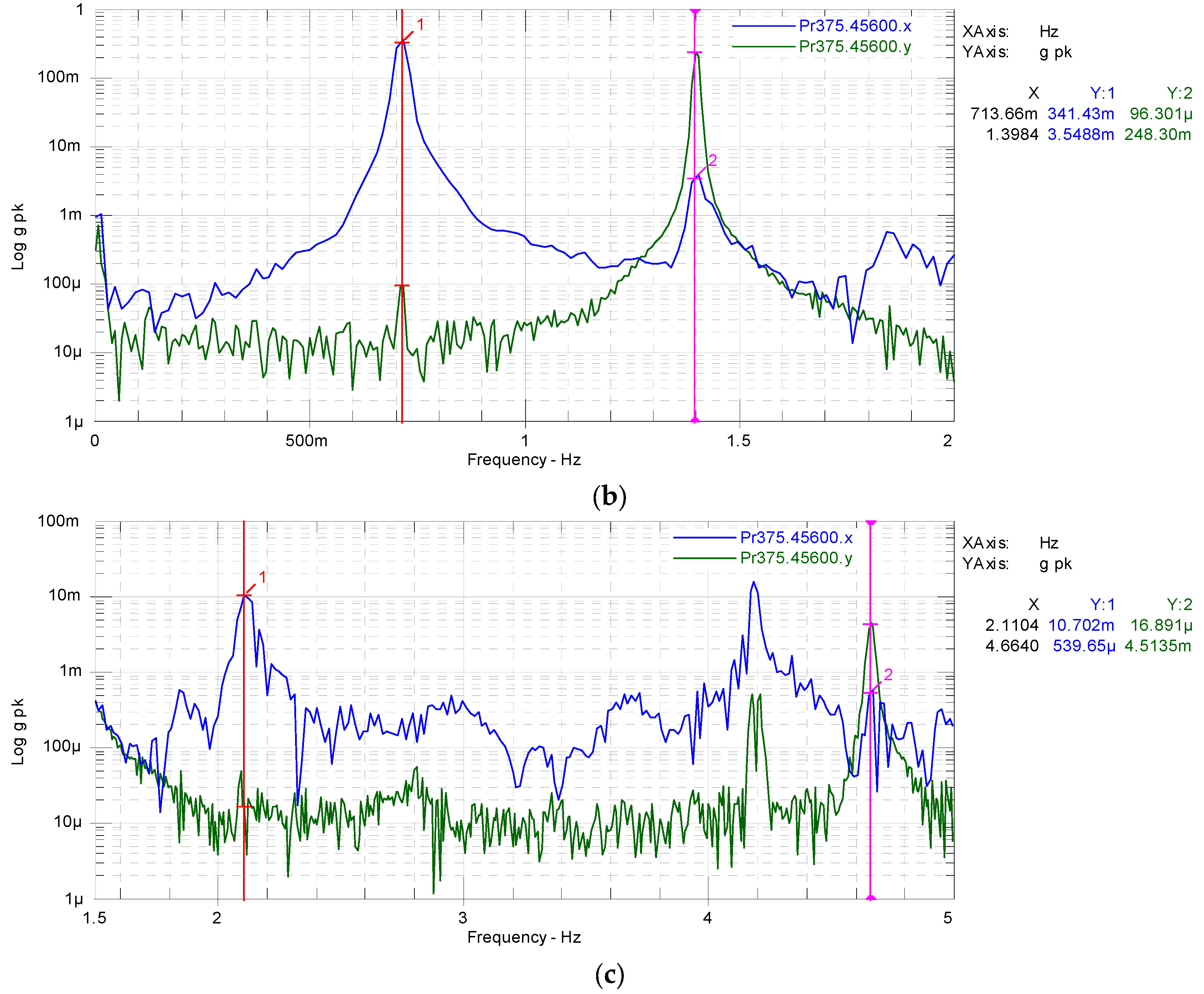
For fatigue testing the first natural frequency of the blade is required. The blade natural frequencies over a range of frequency domain were found by modal testing using hammer impact. The modal testing has been done in both flapwise and edgewise directions for all three states of the blade while the masses were attached to the saddles. The measured natural frequency of the first mode of as received blade was 0.562 Hz. This frequency has not changed when the 200 mm crack was introduced in the blade and when the crack further extended to 1000 mm. However, the first natural frequency had changed slightly by 0.006 Hz for 1000 mm crack when extra mass was added to the saddles.
Before start of calibration and fatigue testing, the blade had two areas of defects at 4% and 71% of blade length. After 184,089 cyclic loading of the blade, the areas that experienced most damage and fracture were between 62% and 74% of the blade length from the root, but no damage was found within the shear web.
The sensitivity of the blade structure to damage under cyclic loading was investigated by introducing a 200 mm crack at 9 m from the root. The crack was created by debonding the web from the spar cap. The crack did not propagate in fatigue loading up to 50% of the estimated target BM. When the load increased to 70% of target BM, some damages have been detected on the pressure side of the blade. However, the 200 mm crack did not propagate under these conditions up to 62,110 cycles.
Finally, the 200 mm crack at 9 m from the root has been extended to 1000 mm. The crack began to propagate when the applied load exceeded 100% estimated target BM. The blade experienced delamination around the crack tip of the 1000 mm crack at the web, adhesive joint failure occurred on the outside of the web, compression failure and sandwich debonding occurred on the inside of the web, and delaminations were visible on the web just below the 1000 mm crack. The test was being conducted with only flapwise loading being applied—it would have been interesting to investigate the rate of crack propagation under edgewise loading as well.
As the blade design was not available, it was impossible to model which crack size would be likely to grow. Therefore, it is not possible to draw any conclusions about whether it is safe to continue operating with a crack of less than 200 mm length in the spar cap—shear web bond. Also, because the loads were not at 100% until the blade had a 1000 mm crack, the load magnitude will of course have been a factor in the increased rate of crack propagation of the larger crack.

 ,
, 


