
A Riding-through Technique for Seamless Transition between Islanded and Grid-Connected Modes of Droop-Controlled Inverters


Abstract
:
1. Introduction
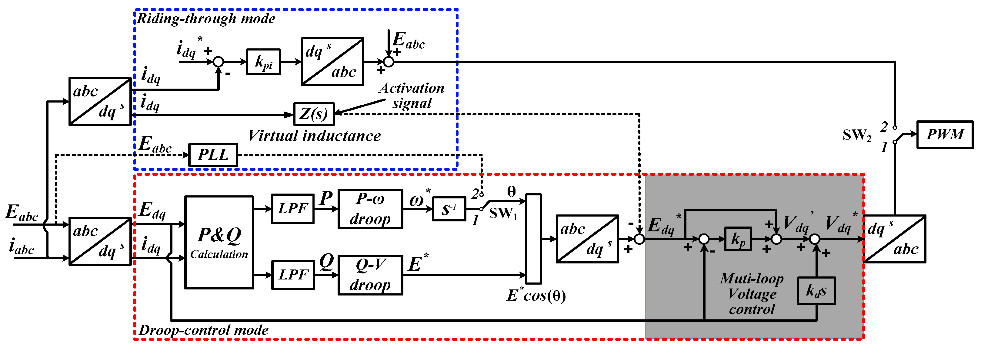
2. Operation Principle
2.1. Droop Control
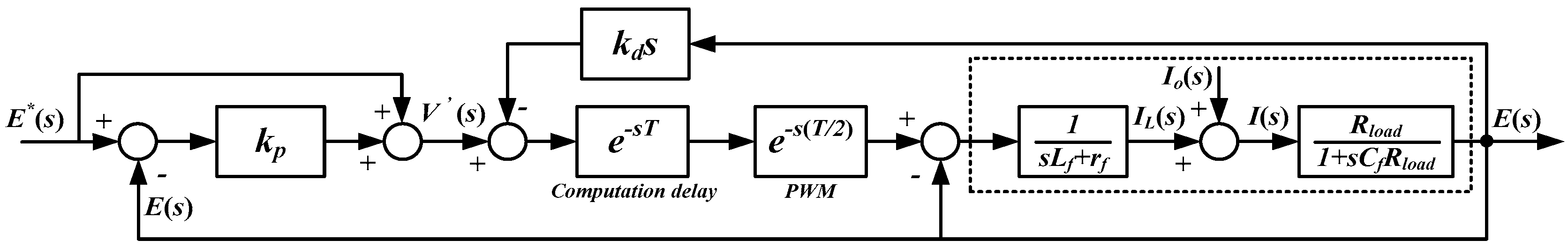
2.2. Multi-Loop Voltage Control
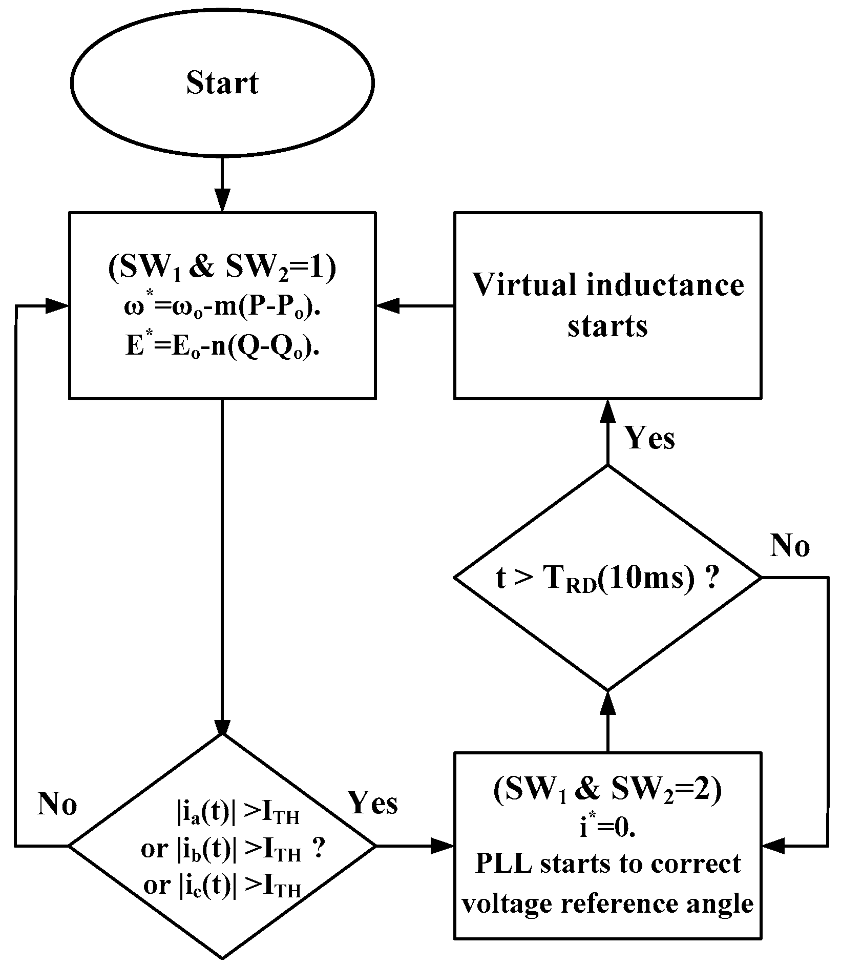
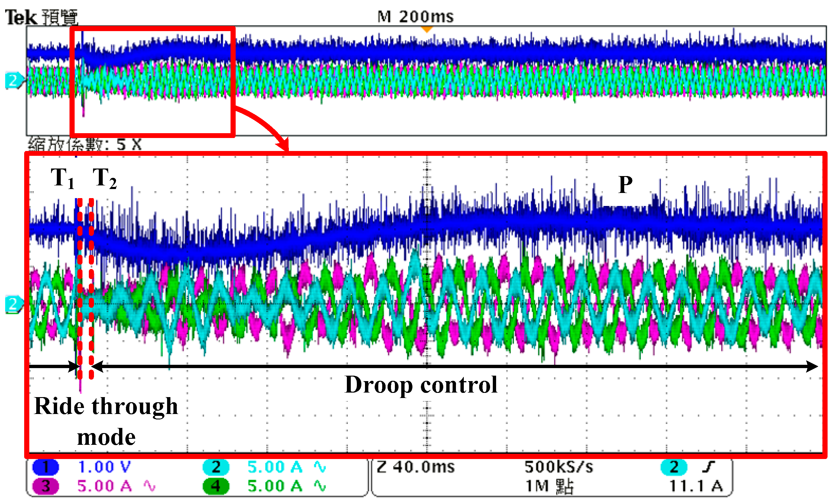
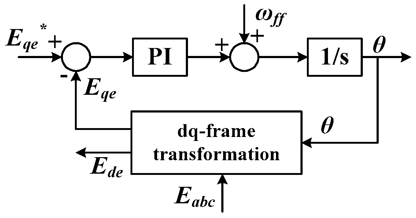
2.3. Riding-through Algorithm
3. Main Control Parameter Design
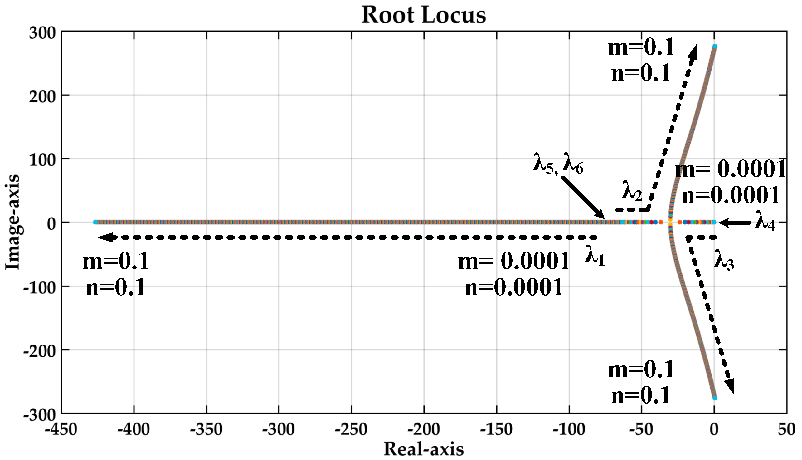
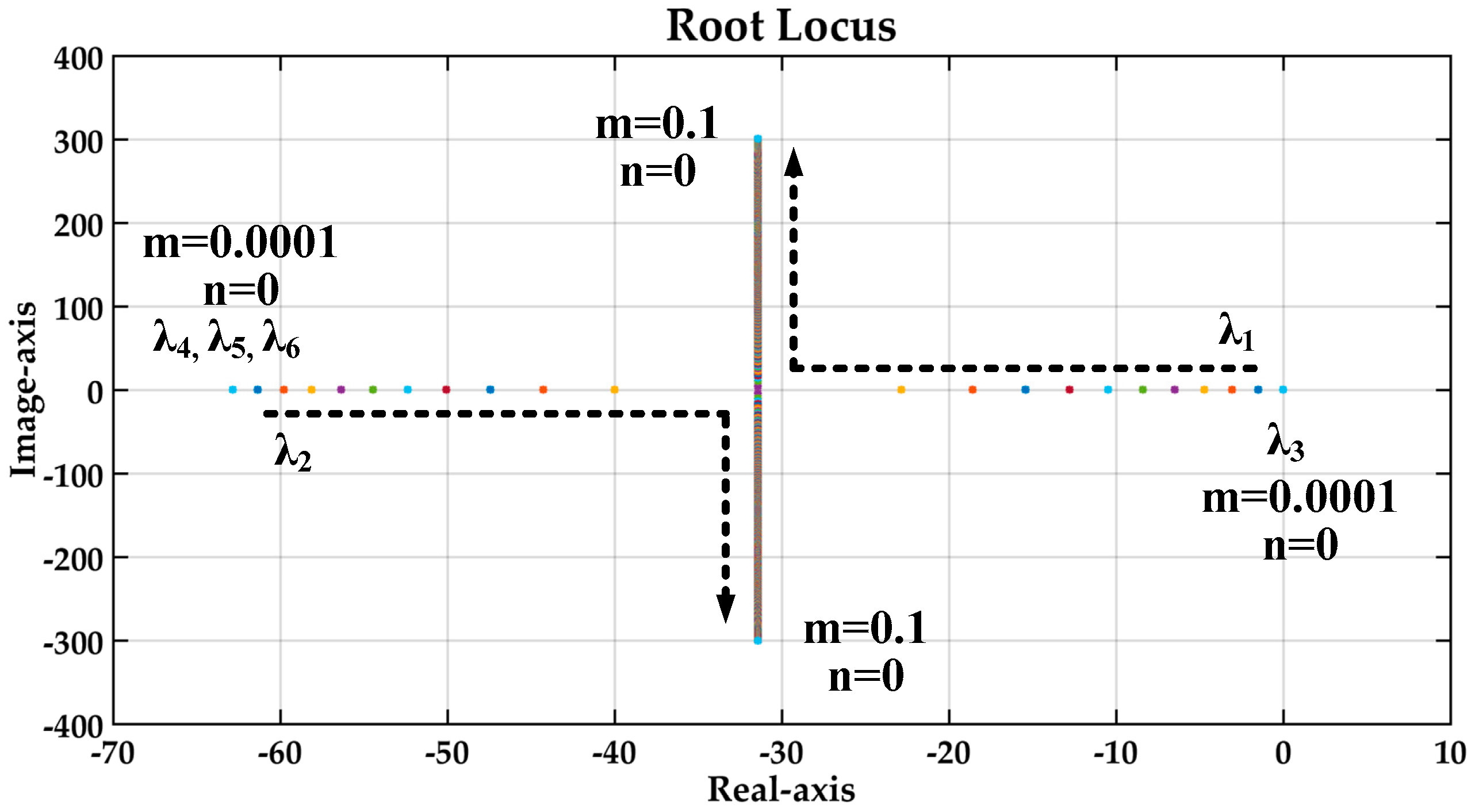
3.1. Droop Coefficients
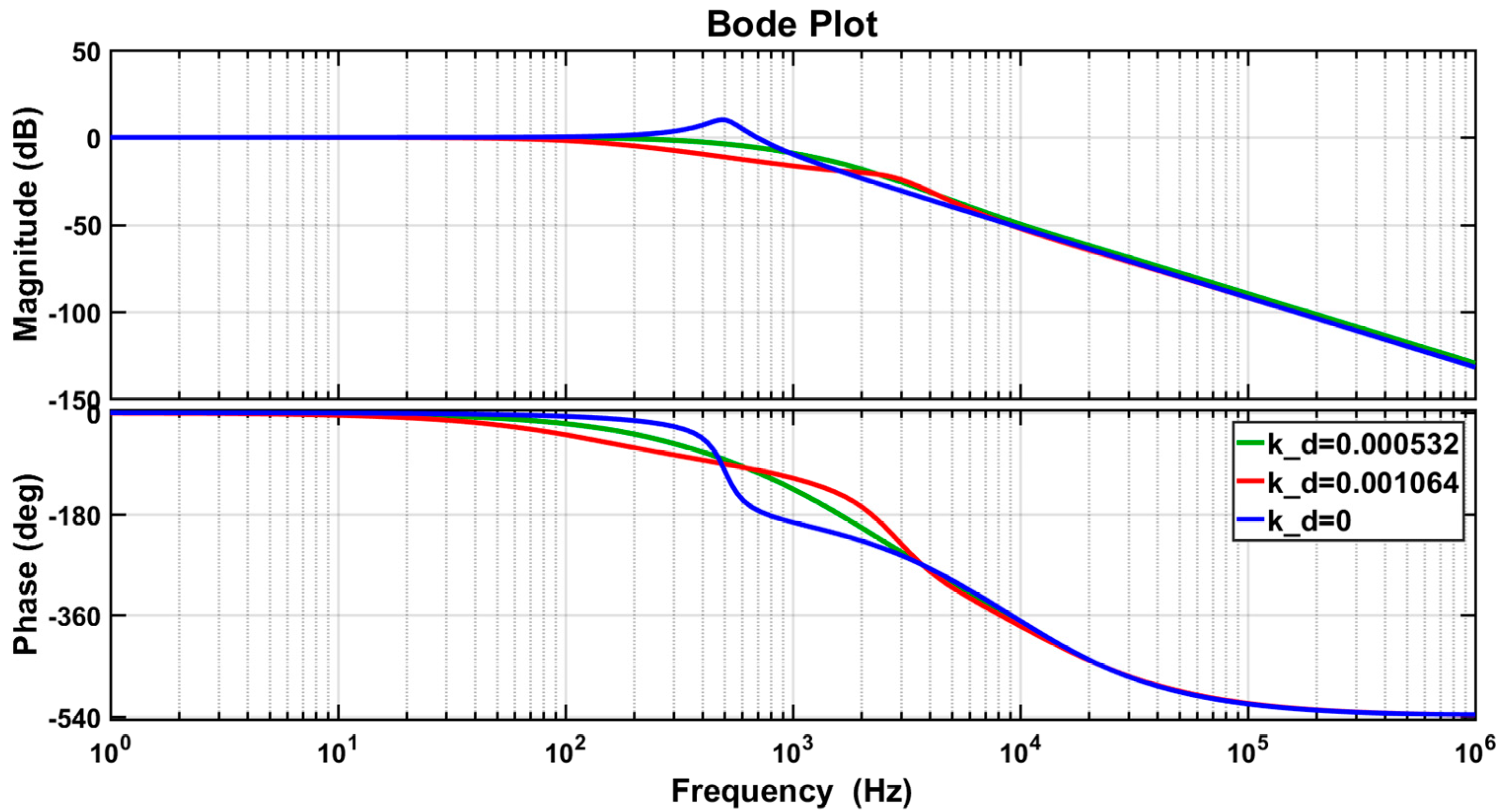
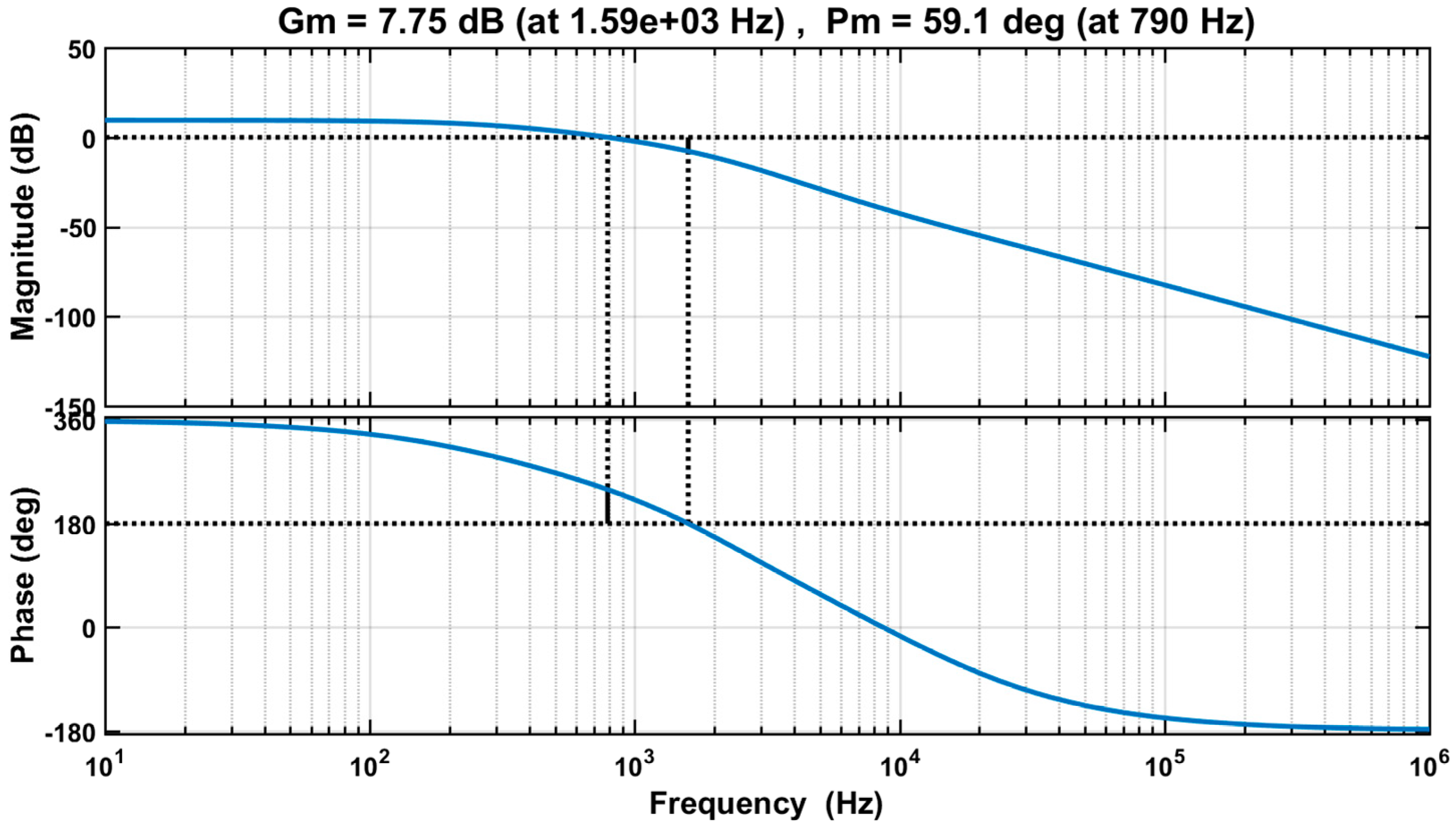
3.2. Multi-Loop Voltage Control
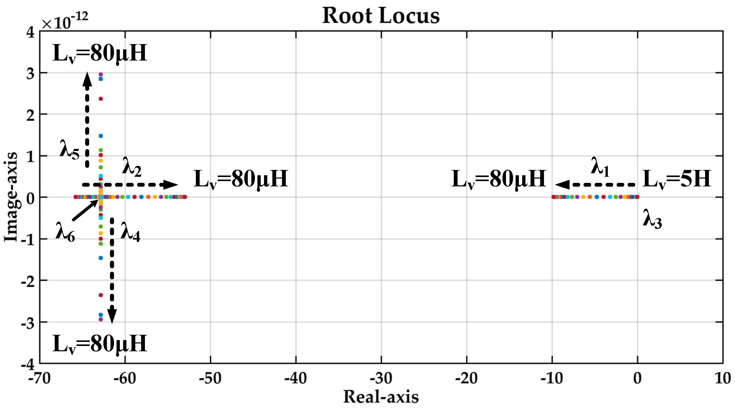
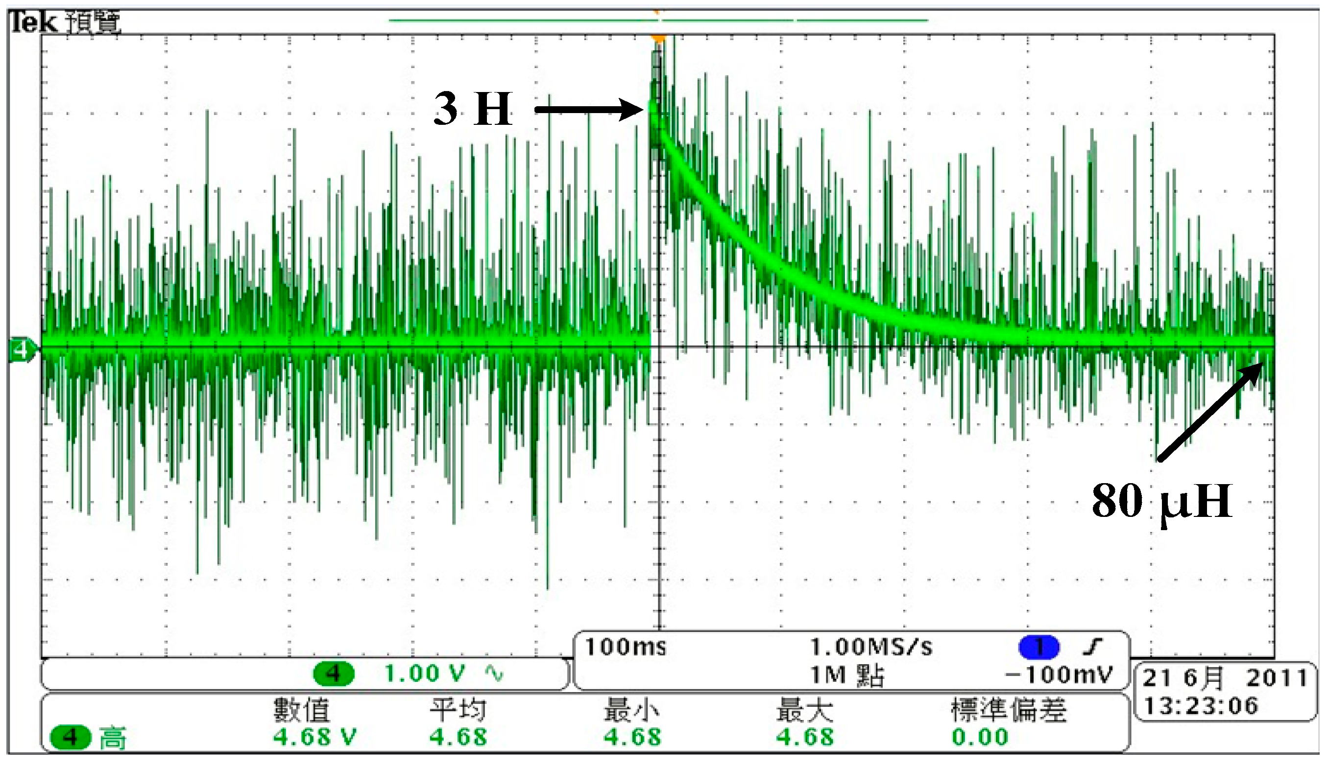
3.3. Virtual Inductance Loop
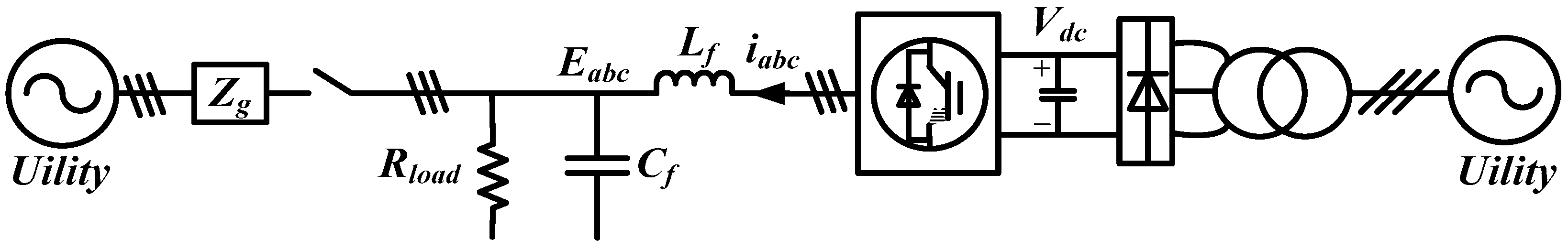
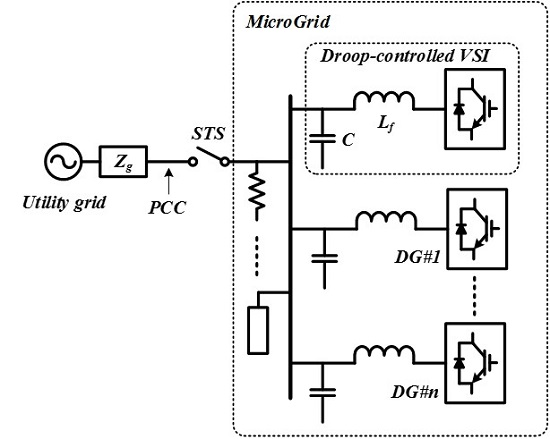
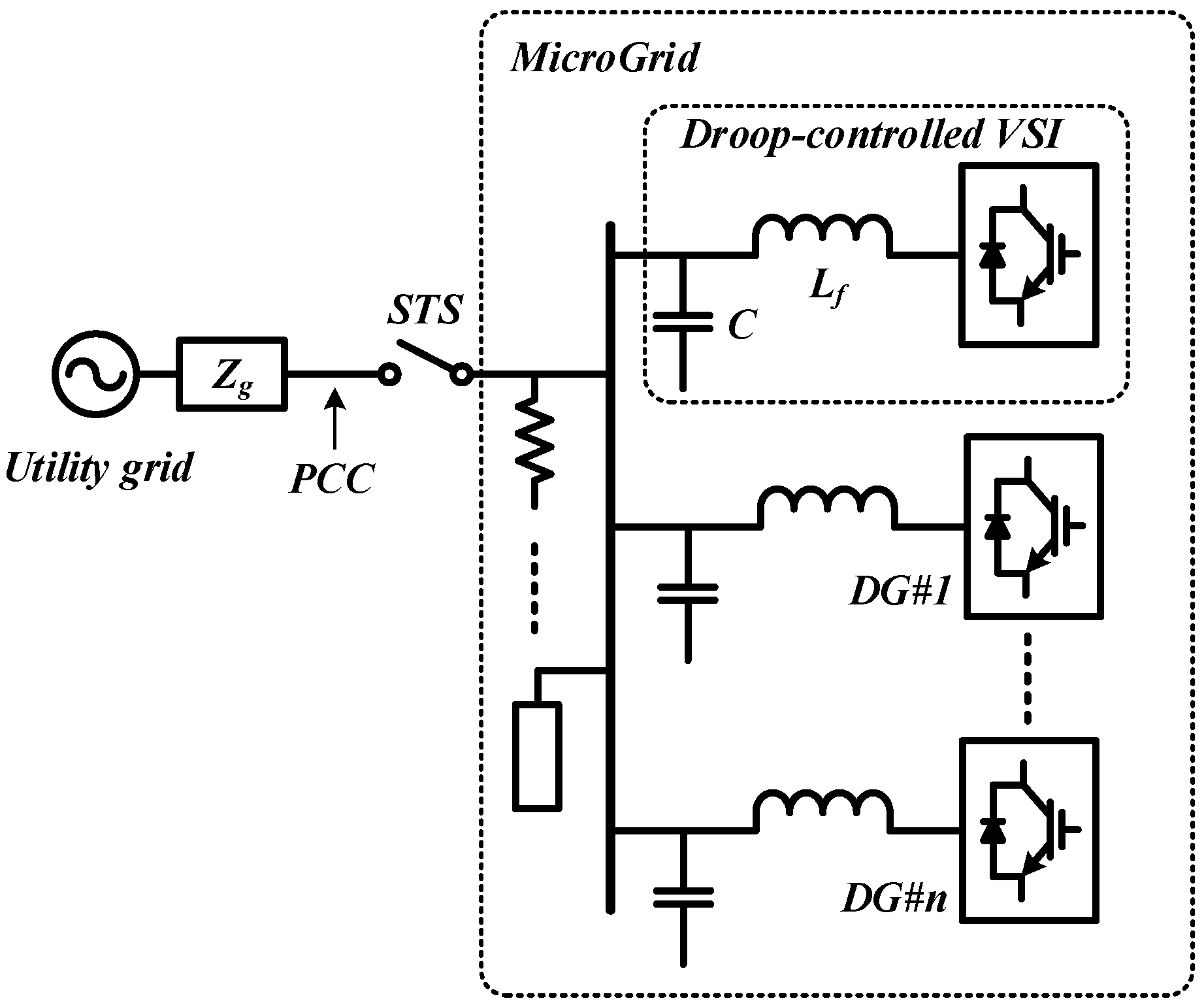
3.4. Impact on an Inverter-Dominated System
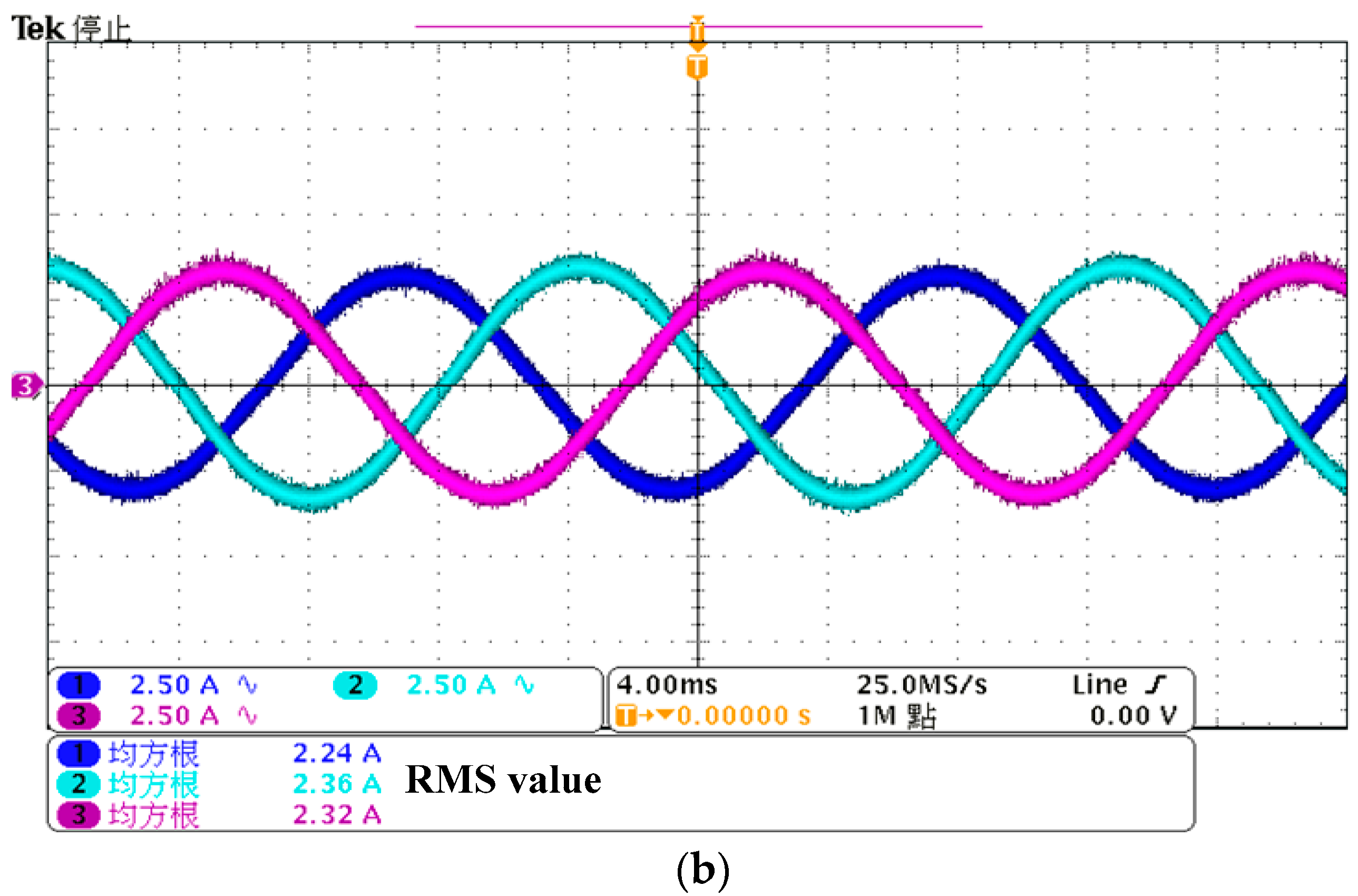
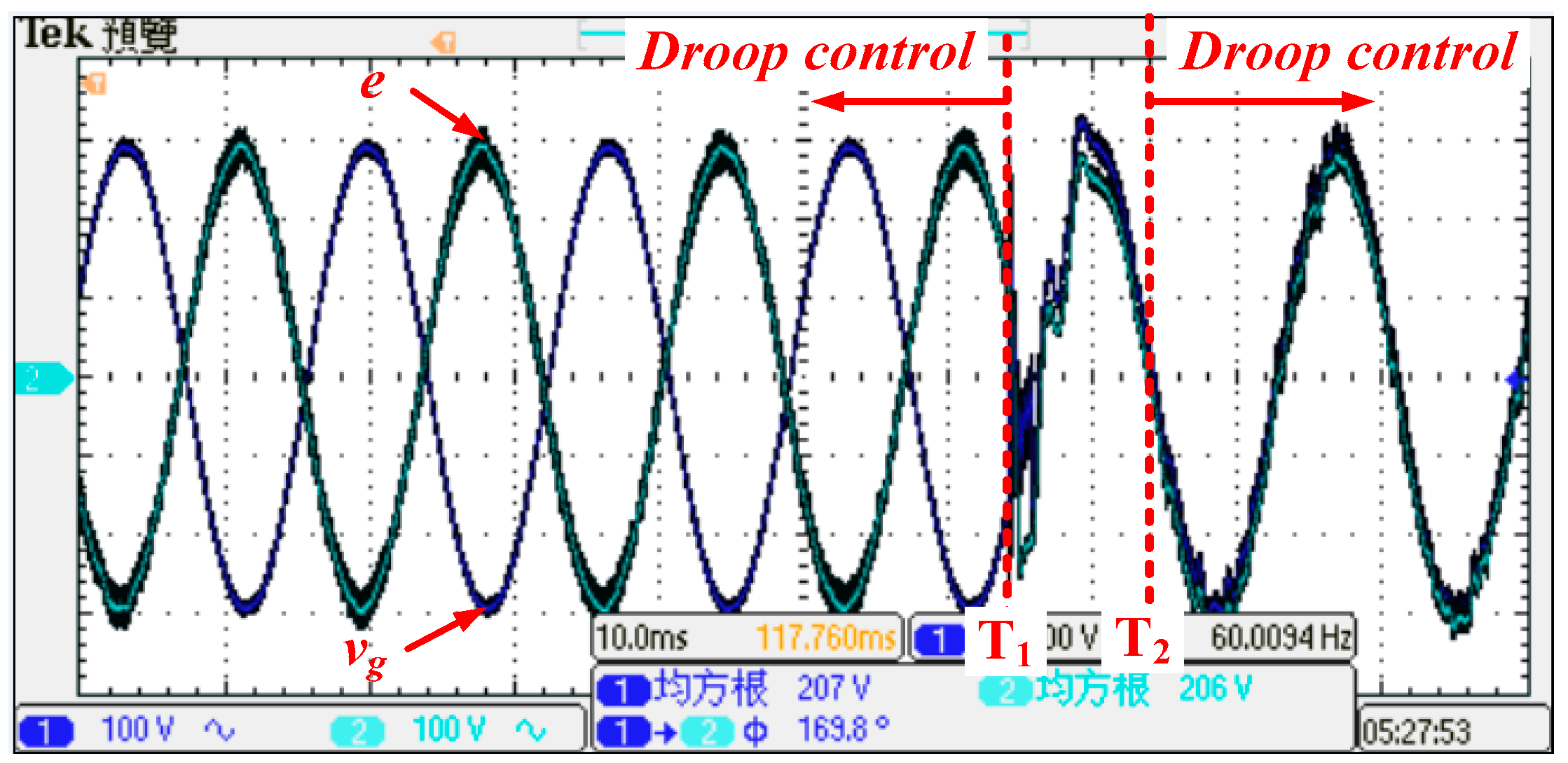
4. Experimental Results
5. Conclusions
Acknowledgments
Author Contributions
Conflicts of Interest
References
- Blaabjerg, F.; Teodorescu, R.; Liserre, M.; Timbus, A.V. Overview of Control and Grid Synchronization for Distributed Power Generation Systems. IEEE Trans. Ind. Electron. 2006, 53, 1398–1409. [Google Scholar] [CrossRef]
- Pahlevani, M.; Eren, S.; Guerrero, J.M.; Jain, P. A Hybrid Estimator for Active/Reactive Power Control of Single-Phase Distributed Generation Systems with Energy Storage. IEEE Trans. Power Electron. 2015, 31, 2919–2936. [Google Scholar] [CrossRef]
- IEEE Std 1547.2TM-2008: IEEE Standard for Interconnecting Distributed Resources with Electric Power Systems. Available online: http://ieeexplore.ieee.org/document/4816078/ (accessed on 6 September 2016).
- IEEE Std 1547.4TM-2011: IEEE Standard for Design, Operation, and Integration of Distributed Resource Island Systems with Electric Power Systems. Available online: http://grouper.ieee.org/groups/scc21/1547.4/1547.4_index.html (accessed on 6 September 2016).
- Lasseter, R. Microgrids. In Proceedings of the IEEE Power Engineering Society Winter Meeting, 27–31 January 2002; pp. 305–308.
- Katiraei, F.; Iravani, R.; Hatziargyriou, N.; Dimeas, A. Microgrids Management. IEEE Power Energy Mag. 2008, 6, 54–65. [Google Scholar] [CrossRef]
- Villeneuve, P.L. Concerns generated by islanding. IEEE Power Energy Mag. 2004, 2, 49–53. [Google Scholar] [CrossRef]
- Bergen, A.R. Power Systems Analysis; Prentice-Hall: Englewood Cliffs, NJ, USA, 1986. [Google Scholar]
- Han, H.; Liu, Y.; Sun, Y.; Su, M.; Guerrero, J.M. An Improved Droop Control Strategy for Reactive Power Sharing in Islanded Microgrid. IEEE Trans. Power Electron. 2014, 30, 3133–3141. [Google Scholar] [CrossRef]
- Yao, W.; Chen, M.; Matas, J.; Guerrero, J.M.; Qian, Z.-M. Design and Analysis of the Droop Control Method for Parallel Inverters Considering the Impact of the Complex Impedance on the Power Sharing. IEEE Trans. Ind. Electron. 2010, 58, 576–588. [Google Scholar] [CrossRef]
- Chandorkar, M.C.; Divan, D.M. Control of parallel connected inverters in standalone AC supply system. IEEE Trans. Ind. Appl. 1993, 29, 136–143. [Google Scholar] [CrossRef]
- Guerrero, J.M.; Vasquez, J.C.; Matas, J.; Castilla, M.; De Vicuna, L.G. Control strategy for flexible microgrid based on parallel line-interactive UPS systems. IEEE Trans. Ind. Electron. 2009, 56, 726–736. [Google Scholar] [CrossRef]
- Chandrokar, M.C.; Divan, D.M.; Banerjee, B. Control of Distributed UPS Systems. IEEE Power Eng. Soc. Gen. Meet. 1994, 1, 197–204. [Google Scholar]
- Guerrero, J.M.; Hang, L.; Uceda, J. Control of Distributed Uninterruptible Power Supply Systems. IEEE Trans. Ind. Electron. 2008, 55, 2845–2859. [Google Scholar] [CrossRef]
- Teodorescu, R.; Blaabjerg, F. Flexible control of small wind turbines with grid failure detection operating in stand-alone and grid-connected mode. IEEE Trans. Power Electron. 2004, 19, 1323–1332. [Google Scholar] [CrossRef]
- Yao, Z.; Xiao, L.; Yan, Y. Seamless Transfer of Single-Phase Grid-Interactive Inverters between Grid-Connected and Stand-Alone Modes. IEEE Trans. Power Electron. 2010, 25, 1597–1603. [Google Scholar]
- Gu, H.; Yang, Z.; Wang, D.; Wu, W. Research on Control Method of Double-Mode Inverter with Grid-Connection and Stand-Alone. In Proceedings of the IEEE 5th International Power Electronics and Motion Control Conference, Shanghai, China, 13–16 August 2006; Volume 1, pp. 1–5.
- Tirumala, R.; Mohan, N.; Henze, C. Seamless transfer of grid-connected PWM inverters between utility-interactive and stand-alone modes. In Proceedings of the Seventeenth Annual IEEE Applied Power Electronics Conference and Exposition, Dallas, TX, USA, 10–14 March 2002; Volume 2, pp. 1081–1086.
- Huang, H.; Kong, L.; Xu, H. Control algorithm research on seamless transfer for distributed resource with a LCL filter. In Proceedings of the Third International Conference on Electric Utility Deregulation and Restructuring and Power Technologies, Nanjing, China, 6–9 April 2008; pp. 2810–2814.
- Vasquez, J.C.; Mastromauro, R.A.; Guerrero, J.M.; Liserre, M. Voltage Support Provided by a Droop-Controlled Multifunctional Inverter. IEEE Trans. Ind. Electron. 2009, 56, 4510–4519. [Google Scholar] [CrossRef]
- Lei, Q.; Yang, S.; Peng, F.Z. Multi-loop control algorithms for seamless transition of grid-connected inverter. In Proceedings of the IEEE 25th Applied Power Electronics Conference and Exposition, Plam Springs, CA, USA, 21–25 February 2010; pp. 844–848.
- Guerrero, J.M.; Matas, J.; De Vicuna, L.G.; Castilla, M.; Miret, J. Wireless-Control Strategy for Parallel Operation of Distributed Generation Inverters. IEEE Trans. Ind. Electron. 2006, 53, 1461–1470. [Google Scholar] [CrossRef]
- Guerrero, J.M.; GarciadeVicuna, L.; Matas, J.; Castilla, M.; Miret, J. Output Impedance Design of Parallel-Connected UPS Inverters with Wireless Load-Sharing Control. IEEE Trans. Ind. Electron. 2005, 52, 1126–1135. [Google Scholar] [CrossRef]
- Hu, S.-H.; Kuo, C.-Y.; Lee, T.-L.; Guerrero, J.M. Droop-Controlled Inverters with Seamless Transition between Islanding and Grid-Connected Operations. In Proceedings of the IEEE Energy Conversion Congress and Exposition, Phoenix, AZ, USA, 17–22 September 2011; pp. 2196–2201.
- Hu, S.-H.; Kuo, C.-Y.; Lee, T.-L. Design of virtual inductance for droop-controlled inverter with seamless transition between islanded and grid-connected operations. In Proceedings of the IEEE Energy Conversion Congress and Exposition, Raleigh, NC, USA, 15–20 September 2012; pp. 4383–4387.
- Liang, J.; Green, T.C.; Weiss, G.; Zhong, Q.C. Hybrid Control of Multiple Inverters in an Island-Mode Distribution System. In Proceedings of the 2003 IEEE 34th Annual Power Electronics Specialist Conference, Acapulco, Mexico, 15–19 June 2003; pp. 61–66.
- Kaura, V.; Blasko, V. Operation of a phase locked loop system under distorted utility conditions. IEEE Trans. Ind. Electron. 1997, 33, 58–63. [Google Scholar] [CrossRef]
- Coelho, E.A.A.; Cortizo, P.C.; Garcia, P.F.D. Small-signal stability for parallel-connected inverters in stand-alone AC supply systems. IEEE Trans. Ind. Appl. 2002, 38, 533–542. [Google Scholar] [CrossRef]


| Description | Symbol | Value | Unit |
|---|---|---|---|
| Local Load (per phase) | Rload | 50 | Ω |
| Filter Inductor | Lf | 5 | mH |
| Filter Capacitance | Cf | 20 | μF |
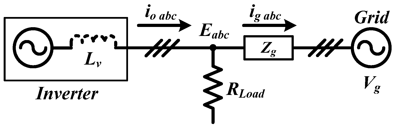
| Grid impedance | Zg | 0.2 + j1.885 | Ω |
| Description | Symbol | Value | Unit |
|---|---|---|---|
| Grid voltage (line-line) | Vg | 220 | V |
| Grid frequency | fg | 60 | Hz |
| Nominal voltage | E0 | 174.7 | V |
| Inverter output power | Po | 1000 | W |
| Nominal Frequency | ω0 | 377 | rad/s |
| P-ω droop | m | −0.0005 | rad/W |
| Q-V droop | n | 0 | V/Var |
| Filter cut-off frequency | ωc | 62.8 | rad/s |
| Nominal virtual inductor | Lvf | 80 | μH |
| Initial virtual inductor | Lvi | 3 | H |
| Time constant | τ | 0.3 | s |
| Proportional gain | kp | 3 | --- |
| Differential coefficient | kd | 0.000532 | --- |
| Riding-through period | TRD | 10 | ms |
| Current threshold | ITH | 10 | A |
© 2016 by the authors; licensee MDPI, Basel, Switzerland. This article is an open access article distributed under the terms and conditions of the Creative Commons Attribution (CC-BY) license (http://creativecommons.org/licenses/by/4.0/).
Share and Cite
Hu, S.-H.; Lee, T.-L.; Kuo, C.-Y.; Guerrero, J.M. A Riding-through Technique for Seamless Transition between Islanded and Grid-Connected Modes of Droop-Controlled Inverters. Energies 2016, 9, 732. https://doi.org/10.3390/en9090732
Hu S-H, Lee T-L, Kuo C-Y, Guerrero JM. A Riding-through Technique for Seamless Transition between Islanded and Grid-Connected Modes of Droop-Controlled Inverters. Energies. 2016; 9(9):732. https://doi.org/10.3390/en9090732
Chicago/Turabian StyleHu, Shang-Hung, Tzung-Lin Lee, Chun-Yi Kuo, and Josep M. Guerrero. 2016. "A Riding-through Technique for Seamless Transition between Islanded and Grid-Connected Modes of Droop-Controlled Inverters" Energies 9, no. 9: 732. https://doi.org/10.3390/en9090732
APA StyleHu, S.-H., Lee, T.-L., Kuo, C.-Y., & Guerrero, J. M. (2016). A Riding-through Technique for Seamless Transition between Islanded and Grid-Connected Modes of Droop-Controlled Inverters. Energies, 9(9), 732. https://doi.org/10.3390/en9090732