1. Introduction
A thermophotovoltaic (TPV) system is capable of directly transducing radiant energy into electrical power [
1,
2]. As such, TPV systems can be applied around high temperature radiant surfaces such as the wall of an exhaust pipe or a furnace, making them a potential candidate for energy harvesters which are becoming an important component in the automatization of micro electromechanical systems [
3]. Although the concept of TPV emerged more than half a century ago, it was only this recent decade that saw its rapid development. Some recent reviews of the technology can be found in the literature [
4,
5,
6,
7].
Typical TPV systems include components such as emitters, filters, mirrors, insulation, heat shields, PV cells, etc., any one of which is, in practice, imperfect and can result in energy losses during operation [
7]. In addition to the material research, an efficient TPV device requires also cleverly designed cavity structures [
4]. While the majority of the previous studies focused on the PV cells [
8], emitters [
9,
10], filters [
11], and other components [
12,
13,
14,
15,
16], we have not found studies on the cavity configuration, which is just as important an aspect of the system as the others [
17,
18]. In the TPV system, components are placed in and around the cavity, whose configuration should be designed appropriately for optimized performance of the system.
In this study we explore the configuration of the TPV system cavity, comprising the emitter, the PV cells, and the mirrors. The energy transduction efficiency from the heat source, house-keeping efficiency for cooling, etc. are beyond the scope of this study. Furthermore, the PV cell efficiency can be divided into sub-components including but not limited to the multiple cell connection efficiency, the ultimate efficiency, the voltage factor, the collection efficiency, and the fill factor [
1]. In this study, only the ultimate efficiency will be considered, since it depends on the spectral characteristics of the cell and is strongly affected by the spectral distribution of radiation within the cavity. The other aspects of cell efficiency are the intrinsic characteristics of the cell and pertain more closely to material science rather than thermal engineering. To summarize, the objective of this study is to design the TPV system cavity, consisting of the emitter, PV cells, and mirrors, altering the spectral and spatial radiation distributions, so that the TPV cavity efficiency can be optimized and the application range extended. Thus, this manuscript focuses solely on the design of the TPV cavity configuration, taking into consideration the aspects that are directly affected by the cavity design while making assumptions to simplify or omit the aspects that are not.
2. Numerical Model
The concentric tubular design, with its simple robustness which makes this geometry a popular choice in many thermal systems [
19], is the most common TPV cavity configuration [
20], as shown in
Figure 1. The emitter constitutes the inner tube, while the PV cells are located on the outer tube. Although geometrically simple, the concentric tubular design can find applications in many combustion and exhaust systems, where tubular structures with high temperature surfaces are readily available. The outer tube can either be fully covered with PV cells (
Figure 1a), or partially covered (
Figure 1b). In the latter configuration, mirrors are utilized to redirect radiation for optimal spatial radiation distribution. For example, in
Figure 1b, eight PV cells are located on the outer tube, and intermittently arranged among them are eight mirrors, that altogether form the entirety of the outer tube. The mirrors reflect the radiation not used by the PV cells back to the emitter to maintain the emitter’s high temperature while conserving energy. This arrangement demands only half the amount of the costly PV cell material compared to that in
Figure 1a, while the efficiency might be sacrificed to some extent.
Rather than forming a loop with the PV cells, the mirrors can take on other shapes to enhance cavity efficiency. In this study, we first investigate the common concentric tubular design. Then, we put forward and optimize two alternative cavity configurations, which we term as the mirror ridge design and the detached mirror design.
The following assumptions are made, taking into consideration both calculation convenience and common engineering practices.
The axial length of the tubular design is long enough so that only the cross-section needs consideration; the physical model can be assumed to be two-dimensional. Also, we assume a steady state heat transfer process.
The cavity is assumed to be in a vacuum. There is no radiation attenuation, radiation scattering, or convective heat transfer in the cavity.
All components have high heat conductivity, so all connected components have uniform temperature, resulting in no conductive heat transfer.
The outer tube (PV cells and mirrors) and emitter temperatures are kept constant at
T0 and 4
T0, respectively, where
T0 = 350 K. This is because it is common engineering practice to control the temperatures of the emitter and the PV cells to maintain a steady power output [
21].
The angle of radiation does not affect the optical properties of the system components. All emission is assumed to be diffusive and Lambertian. Reflection may consist of specular or diffusive fractions, the latter of which is assumed as Lambertian. Reflection of the emitter and the PV cells are fully diffusive. Reflection of the mirrors is 95% specular and 5% diffusive.
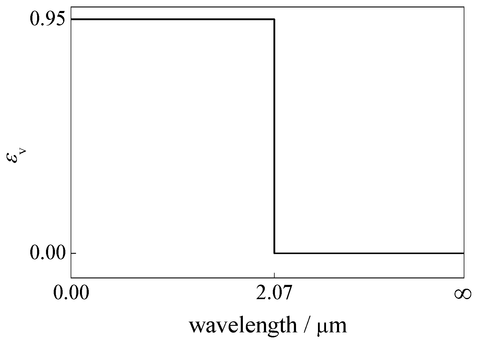
The PV cells are assumed to be coated with a layer of a band-pass frequency-selective surface filter, which reflects, in a fully diffusive manner, all radiation except photons with energy in a band above the PV cell bandgap energy, corresponding to photons with wavelengths longer than
λ0 = 2.07 μm, whereas 95% of the in-band photons are absorbed, as shown in
Figure 2.
λ0 and
T0 satisfies 4
λ0T0 = 2898 μm·K, so the fractional emissive power [
22] contained between 0 and 4
λ0T0 is
f(4
λ0T0) = 0.25. Also,
f(
λ0T0) is very small and can be neglected. Such choices of
λ0 and
T0 are within the range of typical applications [
1].
Table 1 summarizes the optical properties of the TPV system components.
The resulting model involves only surface to surface radiation. For the radiative surfaces, a general boundary condition that defines diffusive emission, diffusive reflection, and specular reflection can be written as:
where:
Iv(r,s) = surface spectral radiation intensity which depends on position r and direction s
εv = spectral emissivity
Ib = blackbody emission intensity
v = frequency
T = local absolute temperature
= diffuse spectral reflectivity = (1 − εv) × diffuse fraction
= specular spectral reflectivity = (1 − εv) × (1 − diffuse fraction)
n = surface normal vector
Ω = solid angle
ss = specular direction
Because Equation (1) involves three spatial coordinates, two directional coordinates and frequency, the calculation of the formal solution for the equation is very time consuming. Thus, the Monte Carlo method and the multiband method are used for the approximation of the directional and spectral dependencies, respectively. For the Monte Carlo method, ten thousand histories of the photons are tracked within the domain.
A commercially available CFD package CFX was used to obtain the numerical results. A validation and mesh independence study was conducted initially. For this process, first, we ran numerical studies for the concentric tubular design with full PV cell coverage, as in
Figure 1a. The boundary condition for the emitter surface remained unchanged, being a blackbody at temperature 4
T0. For the outer tube, the temperature remained at
T0, but the optical property in three cases was set as fully diffuse graybody, fully specular graybody, and spectrally selective diffuse (whose definition conforms to assumption (6) surfaces, respectively. For each of the three cases, four mesh sizes were used to simultaneously conduct a mesh-independence study. The mesh sizes were non-dimensionalized by dividing them by the emitter diameter
d. The ratio of the outer cover inner tube diameter is fixed to two. Then, the net radiative heat exchange rate of two infinite concentric tubes corresponding to the above numerical studies can be calculated analytically [
22]:
where
A1 is the area of the emitter,
A2 is the area of the outer tube,
σ is the Stefan-Boltzmann constant,
ε1 is the emissivity of the emitter, and
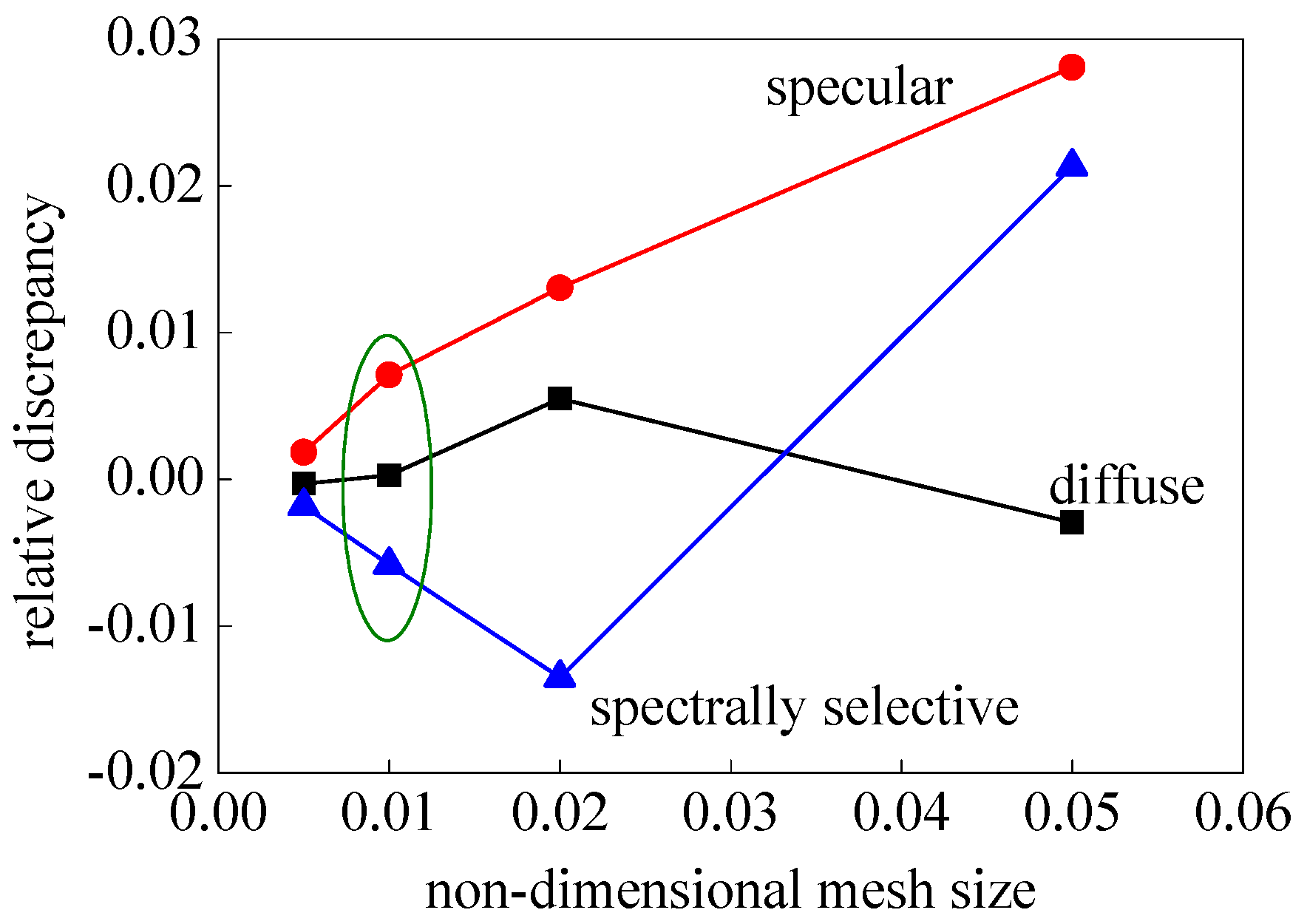
ε2 is the emissivity of the outer tube, which varies for the three cases. Finally, we compare the numerical solutions with the analytical solutions of the net radiative energy exchange between the two tubes for the three cases. This way, the capability of the code to calculate diffuse, specular, and spectrally selective diffuse surface radiation can be tested out separately and the appropriate mesh size identified. The relative discrepancies between the numerical and analytical solutions versus the four non-dimensional mesh sizes are given in
Figure 3. It can be seen that as the mesh sizes decrease, the relative discrepancies between the numerical and analytical solutions converge towards zero. Moreover, with non-dimensional mesh size 0.01 (circled in
Figure 3), the relative discrepancies fall below 0.01, which is acceptably small. Thus, the non-dimensional mesh size 0.01 was chosen for the simulations.
3. Thermophotovoltaic (TPV) Cavity Configuration 1
Generally, the efficiency of a given finite-sized system is the ratio of useful output to total input. For the current model, the total input is the total blackbody emissive power of the emitter:
where
σ is the Stefan-Boltzmann constant.
For a TPV system producing only power, the useful output is the power generated at the PV cells by transducing a proportion of the incoming radiation into electric charge. The modeling of the transduction is an intricate subject for debate [
1], and not the main focus of this paper. Here, we assume a band-pass frequency selective surface filter for the PV cell surface. The total net radiative energy transfer rate of the PV cell surfaces,
QPV, is considered here as the useful output. That is, we assume the ratio of the absorbed radiation over the power rate to be 100%. Thus, we define the power generation efficiency
ηP, which is the ratio of
QPV over
Ebe. This efficiency is essentially the efficiency given by the detailed balance proposed by Shockley and Queisser [
23], neglecting the efficiency decrease resulting from recombination. The reason to neglect recombination is because it contributes little to the efficiency loss of the TPV system, in comparison to the spectrum losses, which contribute towards the vast majority of lost power, and are greatly affected by the cavity design, and thus a focal point of the study. Also, the effect of redistribution is dependent on the cell voltage, which pertains to the electronic aspect of the system, an aspect beyond the scope of this study. When the TPV system is used for combined heat and power (CHP) applications, the total output is the sum of the generated power and heat. So in addition to
ηP, there is also the heating efficiency
ηH, which is the ratio of the radiant energy reflected back to the emitter over
Ebe. We will consider and optimize both efficiencies.
Moreover, since it is sometimes desirable to maintain the ratio of power to heat generation at a required value, the ratio between the two efficiencies r = ηP/ηH is also of interest. For a robust configuration, the value of r should cover a wide range, which enables the TPV system to satisfy an extended range of demand with little adjustment.
When the outer tube is fully covered with PV cells, ηP tends towards the theoretical maximum with increasing outer tube diameter, as predicted by Equation (2). However, this is not very economical or practical, since it requires much PV cell material and space. We aim to achieve high efficiency and robustness with a limited amount of material and decreased size. Rather than having almost no design (only two concentric tubes), we introduce configuration to the cavity by adding relatively more available mirrors whose shape and placement are free to change within defined constraints.
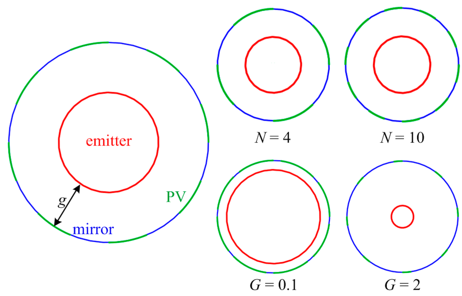
First we consider the configuration in
Figure 1b, where mirrors are placed intermittently between the PV cells. The variables that we will change are the number of mirrors
N and the non-dimensional gap between inner and outer tubes
G =
g/
d, as shown in
Figure 4, where
g is the gap of the cavity. Three additional constraints are provided:
The diameter of the emitter d remains constant, and will be used to non-dimensionalize other length variables.
The total area of the PV cells equals that of the emitter, i.e., in all the schematics, the total length of the green arcs is equal to the circumference of the red circle.
The PV cells have the same area as one another, and are uniformly spaced.
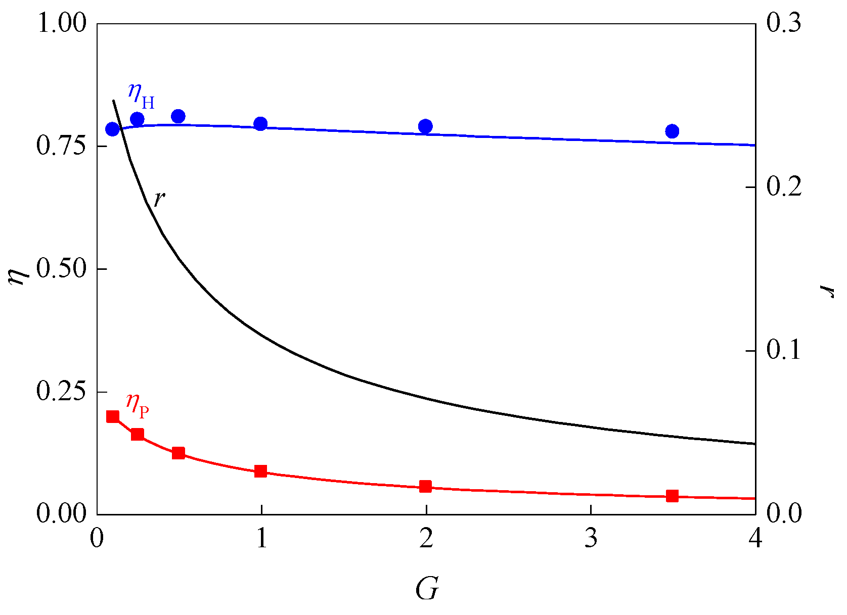
We denote this design as configuration 1, i.e., the concentric tubular design with looped mirrors. Numerical simulations were run for different combinations of design parameters
N and
G. The results are given in
Figure 5. It was observed that the number of mirrors
N has almost no effect on the efficiencies, so only the change in
G is plotted. Six values of
G are considered, and the results are fitted to third order polynomial curves, based on which the curve
r is calculated. It can be seen that
ηH reaches an inconspicuous maximum around
G = 0.5, otherwise the range of
ηH remains quite stable at around 0.75–0.78. As expected,
ηP tends toward the maximum 0.2375 when
G tends toward zero, since then fewer mirrors are employed and less radiation is reflected back to the emitter. However,
ηP decreases with increased
G, down to about 0.033 at
G = 4. As a result, a decreasing
r curve can also be observed, ranging from about 0.26 to 0.04.
Due to the lack of freedom to change, configuration 1 may not be the most efficient in terms of the two efficiencies and the range of r. So two alternative designs are proposed which can provide high efficiency as well as a wider range of the power to heat ratio.
4. Thermophotovoltaic (TPV) Cavity Configuration 2
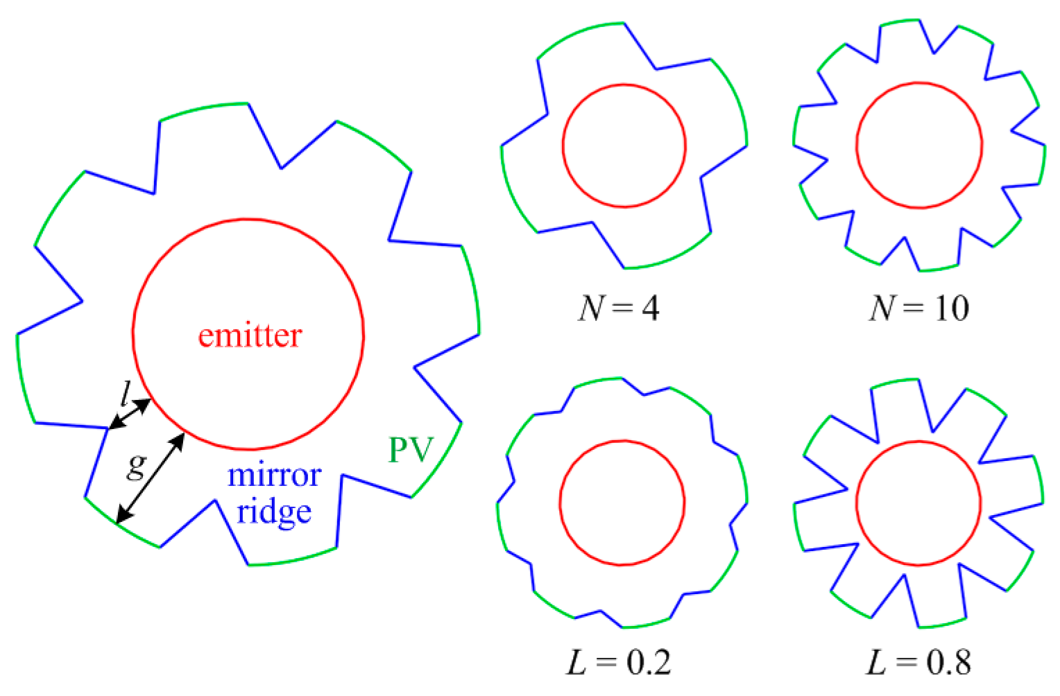
Now consider configuration 2, the mirror ridge configuration, shown in
Figure 6. Instead of forming a loop with the PV cells, the mirrors take on a ridge shape. The mirrors connect to the PV cells, but extend into the cavity. The gap between the PV cells and the emitter
g is fixed at
g/
d =
G = 0.5. The other constraints are the same as those in
Section 3. The varied parameters are the number of mirrors
N, and the gap between the tip of the ridge to the emitter, written in non-dimensional form as
L =
l/
g, which tends to zero as the ridges come close to the emitter but tends to unity as the ridges move further away.
Numerical results of the TPV system adopting configuration 2 are fitted and plotted in
Figure 7. With more mirrors added, the variation in terms of the efficiencies with varying
L increases. That is, the addition of mirrors introduces more freedom to change, in accordance to the Constructal theory [
18], leading to more robust systems. For
N = 2,
ηH decreases from about 0.77 to 0.74 with increasing
L. For
N = 10,
ηH decreases from about 0.78 to 0.58 with increasing
L. As such, all the
ηH curves decrease with increasing
L. The slope of this decrease becomes steeper with increasing
N. The effect of
N is less pronounced but still present for
ηP, which increases with increasing
L. The range of
ηP is about 0.12–0.2 for
N = 4–10. This range shrinks to about 0.15–0.18 for
N = 2.
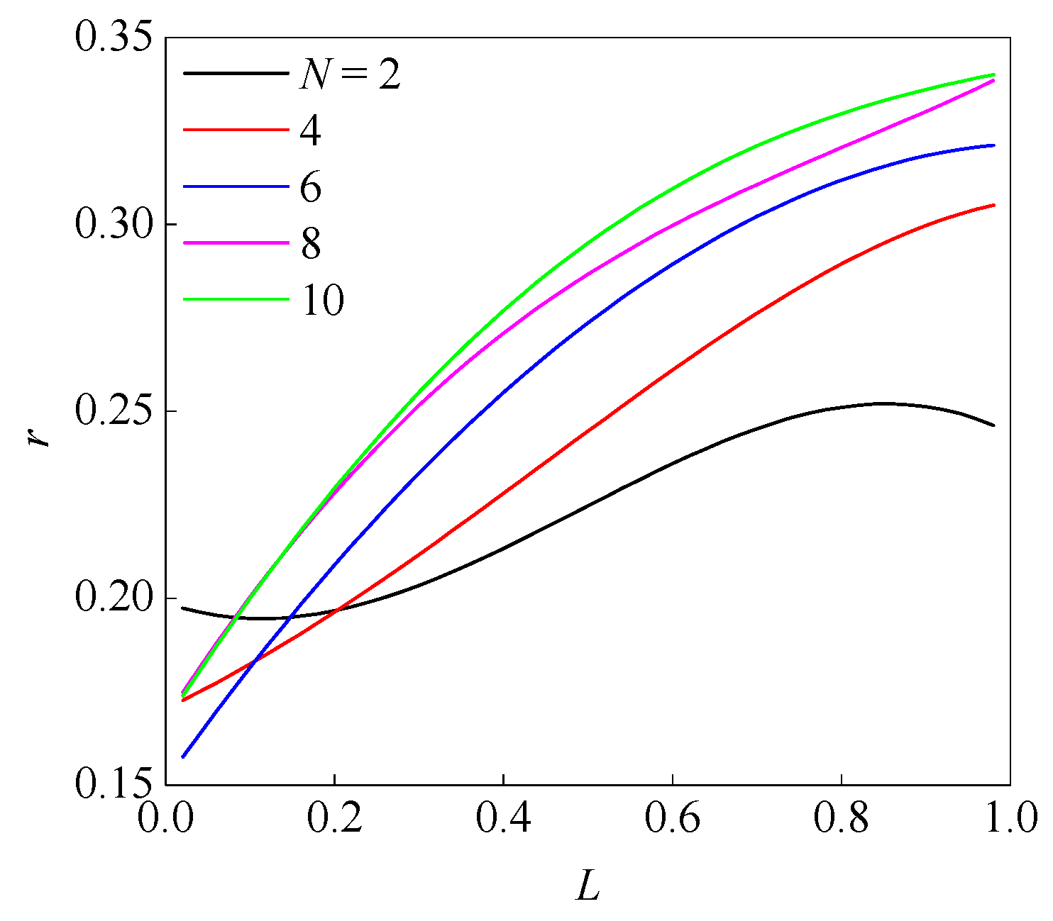
Figure 8 shows the results of the power to heat ratio
r for configuration 2. The
r-
L curves for
N = 4–8 are monotonously positive. The value of
r ranges from about 0.15 to 0.33. The
r-
L curve for
N = 2, however, shows an S shape, with the minimum 0.19 and maximum 0.25 occurring at about
L = 0.2 and 0.8, respectively.
Compared to design point G = 0.5 in configuration 1, where ηP = 0.12 and ηH = 0.81, configuration 2 achieved higher ηP = 0.21, but a slightly lower ηH = 0.79. The power to heat ratio r in configuration 2 ranged from 0.16–0.34. Therefore, the application range of the TPV system was extended.
5. Thermophotovoltaic (TPV) Cavity Configuration 3
Now consider configuration 3, the detached mirror configuration, shown in
Figure 9. In addition to the concentric geometry, detached mirrors are placed inside the cavity space, in such a manner that they align with the outer tube mirrors, but expose the PV cells to the emitter. Changing from a flat mirror, for which the parameter
Θ = 180°, the mirrors can bend at the center into smaller angles
Θ. Also, the mirrors can move along the radial direction of the cavity, which is defined by
L =
l/
g. Wherever the mirrors are placed, they cover the same angular span as the corresponding outer tube mirror, as shown by the dashed lines in the left of
Figure 9. The constraints given in
Section 3 still hold. Thus the degrees of freedom of configuration 3 are
N,
Θ, and
L.
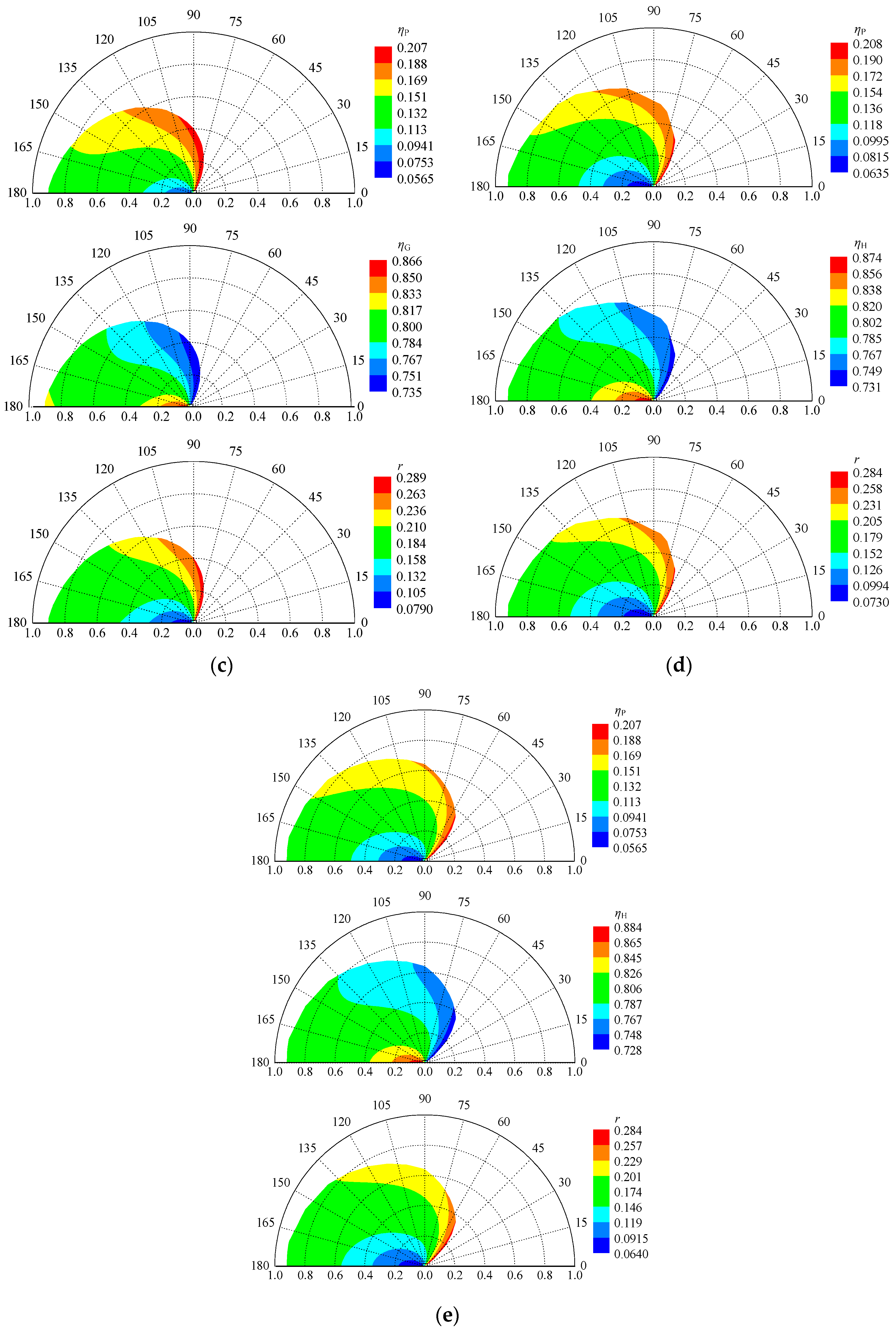
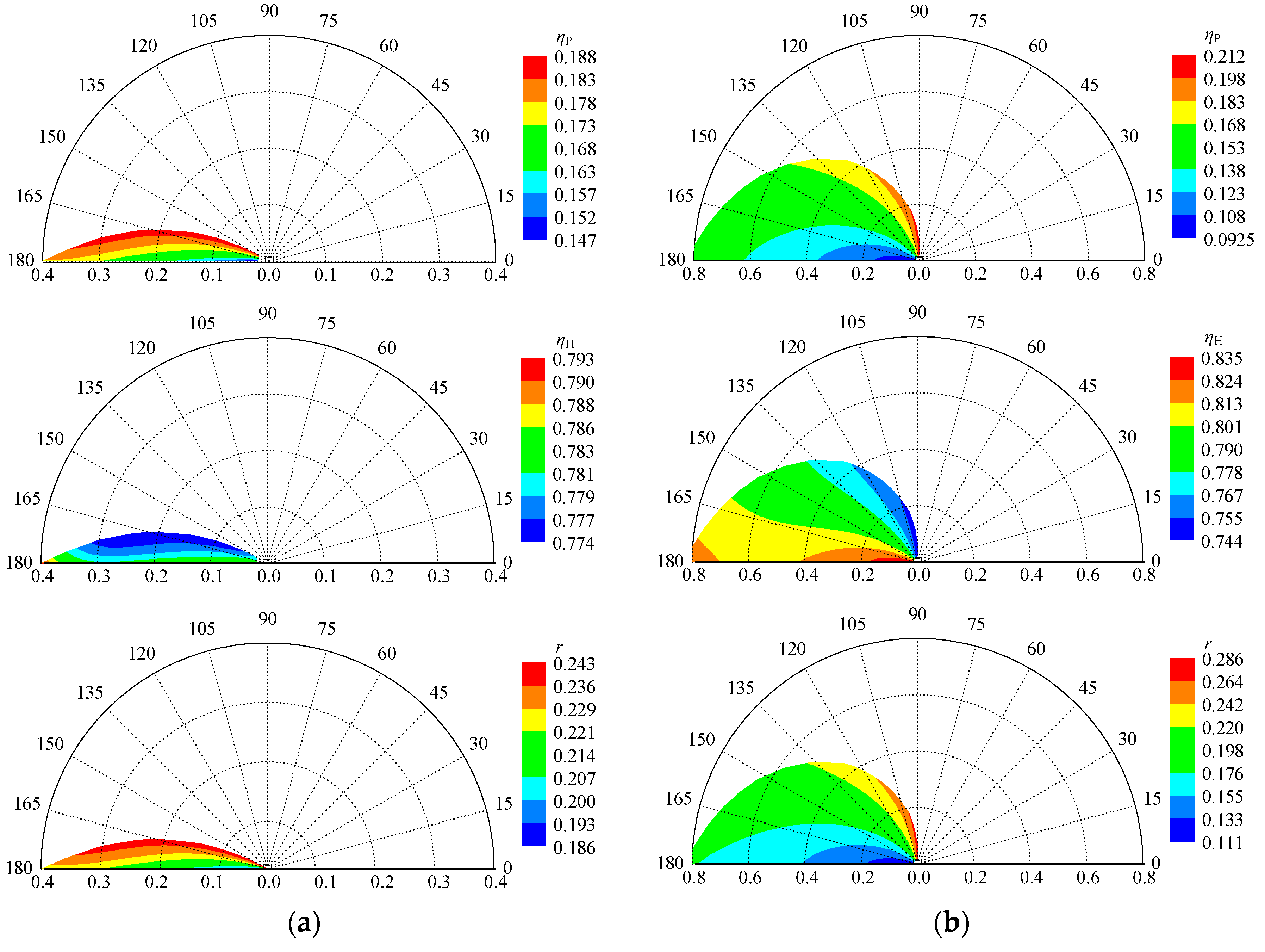
The numerical results are shown in
Figure 10. Since there are three variables, we used color contours for their presentation. From
Figure 10a–e,
N increases from 2–10. Each sub-figure contains three graphs, corresponding to the depiction of the two efficiencies
η and the power to heat ratio
r. The graphs are given in polar form, with the radial axis, circumferential axis, and color contours representing
L,
Θ, and the value of the results, respectively. The color red represents the maxima, while blue represents the minima.
From N = 2 to 10, a gradual increase in the area of the colored plot can be observed. This is because, with smaller N, the design space is much smaller than that of larger N. When there are fewer mirrors, they can only change so much before reaching the boundary of the cavity. However, with more but smaller detached mirrors, more radial distance L can be covered with larger angle Θ.
Generally, for ηP, the maxima occur at the smallest Θ and L. The minima appear when Θ = 180°, at the smallest L. This trend is also true for r. The trend for ηH is the opposite.
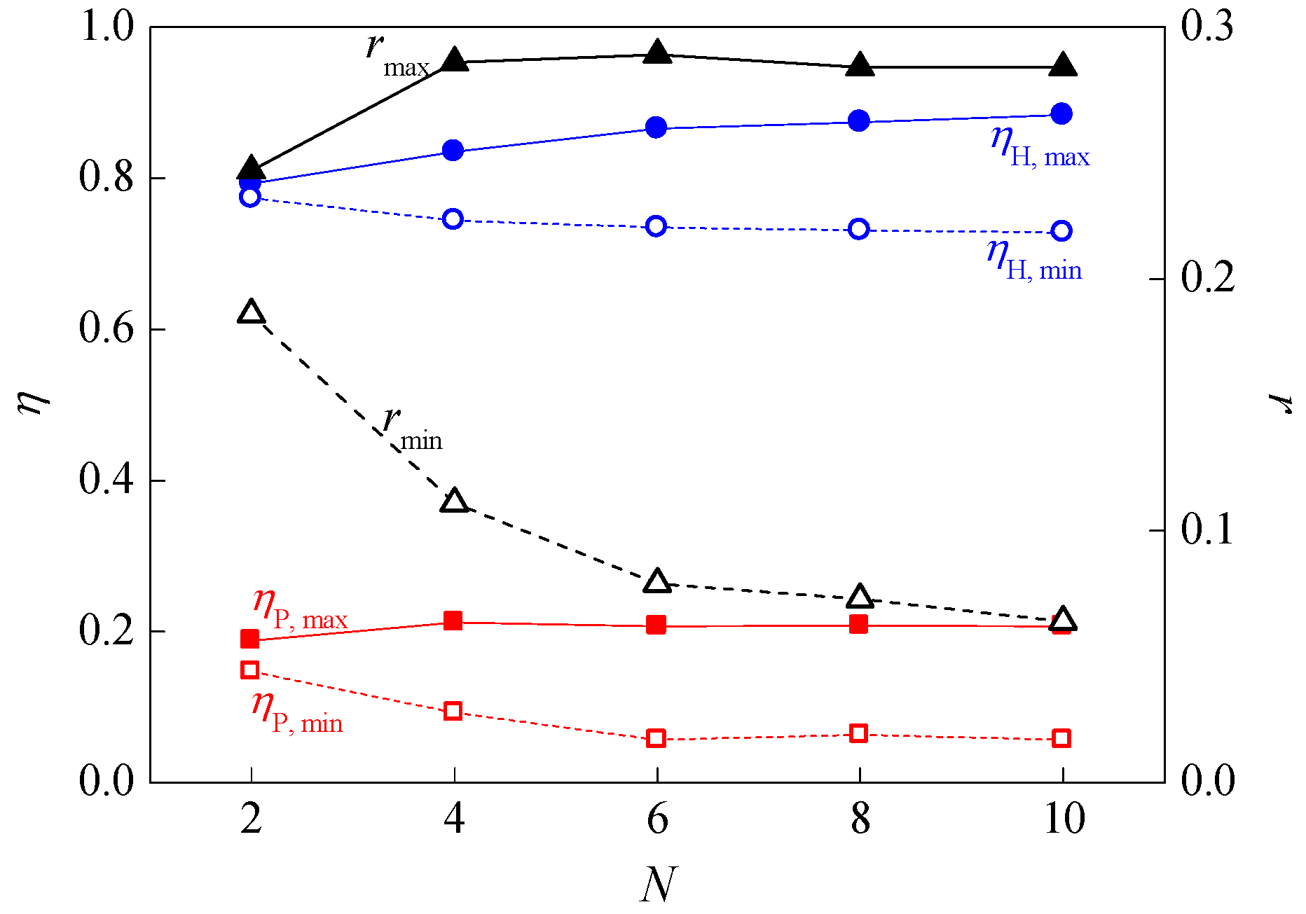
The maxima and minima of
ηP,
ηH, and
r for varying
N are summarized in
Figure 11. The maxima of both efficiencies increase with increasing
N, and vice versa for the minima. The highest value of
ηH can reach 0.88, and 0.21 for
ηH, the former larger than that achieved in configuration 2.
For r, the maxima increase from N = 2 to 4, at which point they decrease again with increasing N. The minima of r decrease monotonously with N. In the range N = 4–10, the decrease rate of the minima of r is much faster than that of the maxima of r. To conclude, with the use of more mirrors, a wider range of r can be achieved.
6. Conclusions
In this study, the TPV system cavity, which consists of the emitter, the PV cells, and the mirrors, was optimized in terms of the power and heat efficiencies. This was done through varying the shape of the mirrors in the TPV system cavity. In addition to the common concentric tubular geometry, two cavity configurations were proposed, which were the ridge design and the detached mirror design. Various design parameters, such as the number of mirrors, the ridge to emitter gap, the mirror angles, etc., were altered for optimal performance. The results show that more mirrors add more freedom to change the configuration, increasing its design space, and can provide better efficiencies and a wider range of system applications. Thus, the configuration of the cavity is an important aspect of TPV system design and should not be neglected.


