Article

Simultaneous Optimization of Topology and Component Sizes for Double Planetary Gear Hybrid Powertrains

1
Department of Mechanical Engineering, School of Mechanical Engineering, Nanjing University of Science and Technology, 200 Xiaolingwei Street, Nanjing 210094, China
2
Department of Mechanical Engineering, University of Michigan, G041, Walter E. Lay Autolab, 1231 Beal Ave, Ann Arbor, MI 48109, USA
*
Author to whom correspondence should be addressed.
Energies 2016, 9(6), 411; https://doi.org/10.3390/en9060411
Submission received: 28 February 2016 / Revised: 10 May 2016 / Accepted: 20 May 2016 / Published: 26 May 2016

Abstract

:
Hybrid powertrain technologies are successful in the passenger car market and have been actively developed in recent years. Optimal topology selection, component sizing, and controls are required for competitive hybrid vehicles, as multiple goals must be considered simultaneously: fuel efficiency, emissions, performance, and cost. Most of the previous studies explored these three design dimensions separately. In this paper, two novel frameworks combining these three design dimensions together are presented and compared. One approach is nested optimization which searches through the whole design space exhaustively. The second approach is called enhanced iterative optimization, which executes the topology optimization and component sizing alternately. A case study shows that the later method can converge to the global optimal design generated from the nested optimization, and is much more computationally efficient. In addition, we also address a known issue of optimal designs: their sensitivity to parameters, such as varying vehicle weight, which is a concern especially for the design of hybrid buses. Therefore, the iterative optimization process is applied to design a robust multi-mode hybrid electric bus under different loading scenarios as the final design challenge of this paper.

1. Introduction

Tightening emissions and fuel economy standards are strong driving forces behind vehicle electrification. The future Corporate Average Fleet Average (CAFÉ) standard requires fuel economy at 54.5 miles per gallon (unadjusted) for passenger cars by 2025 [1], a significant increase from today’s fleet average of about 31 miles per gallon. This fuel economy target is difficult to achieve through improving traditional powertrains using internal combustion engines. However, it can be met quite easily by hybrid electric vehicles (HEVs) and plug-in hybrid electric vehicles (PHEV).
From the perspective of power flow between the engine, the motor/generators (MGs) and the vehicle driveshaft, HEVs are generally divided into three types: series, parallel, and power-split. Among all three types, the power-split type, which uses planetary gear (PG) sets, has dominant market share [2]. This is mainly because the engine in the power-split HEV is decoupled from the vehicle speeds and can operate efficiently while much of the power flows in the mechanical path and is, thus, efficient. Therefore, about 85% of HEV and PHEV market share in the US is occupied by power-split HEVs [2].
It should be noted that the power-split powertrains are more complex than series and parallel hybrids and the control is far more complex [3]. In addition, multiple operating modes can be achieved when clutches are augmented to a power-split configuration [4]. With the introduction of clutches, the complexity of hybrid powertrains becomes unprecedented. The high system complexity provides more freedom for achieving better fuel economy, performance, cost, and comfort [5]. The multiple objectives and system complexity result in a nonlinear constrained optimization problem that is not straightforward to solve.
Researchers and engineers typically optimize the powertrain designs from three perspectives: control strategy, component sizes, and system topologies. The latter two aspects, component sizing and topology optimization, are usually integrating with control optimization problems to minimize fuel consumption. A rule-based control strategy is easy to design, but is highly dependent on the experience of engineers and cannot guarantee optimality [6]. An equivalent consumption minimization strategy (ECMS) optimizes the engine power instantaneously, but the equivalent fuel consumption factor requires tuning if the design or driving conditions are changed [7,8]. Dynamics programming (DP) guarantees global optimality, but its computation burden grows exponentially with the number of state and input variables [9], which makes it unsuitable for high-dimension systems. Some literature tries to reduce the computational burden by using a local approximation of the gridded cost-to-go [10,11]. However, it still requires long computation time that makes it unsuitable for large-scale system control or design studies. The convex optimization method computes quickly, but are not appropriate for power-split or multi-mode HEVs due to the lack of convexity [12,13]. Up to today, power-weighted efficiency analysis for rapid sizing (PEARS) is the only known method that can be used to solve multi-mode HEV control problems with demonstrated optimality and can be computed orders of magnitude faster than DP [14].
In terms of component sizing, most literature tried to identify the most fuel-efficient design in the bi-level frameworks [15,16,17], where the energy management strategy needs to be optimized for each component size candidate. Due to the iterations, the bi-level frameworks is time-consuming. To reduce computational load, people sometimes search the optimal designs with heuristic optimization methods to avoid looping through all designs, like using genetic algorithms (GA) [16], particle swarm optimization (PSO) [17], and self-adaptive differential evolution algorithms [18], under the constraints of performance, emissions, and cost [19]. Other studies tried to address this problem more efficiently. One method that optimizes the component sizes and control strategy simultaneously is convex optimization [20]. One study proposes a rule-based design method based on the defined hybridization ratio after analyzing the results from DP [21].
Recently, researchers have been shifting their focus to the configuration optimization that received less attention in the past, but shows great potential to improve the energy efficiency. It is known that the number of possible topologies for the parallel hybrid is very limited and can be evaluated one by one easily [22]. The power-split HEVs, however, especially when extended to multi-mode HEVs, has exponentially increasing number of designs with the number of components (PGs and clutches) and their exhaustive analysis is not easy.
The optimal topology studies started from single-PG HEVs [4]. Different modeling methods, i.e., automatic modeling [23,24] and bond graphs [25], have been applied to study all possible single-PG designs. Since the design space for a single-PG hybrid is not large, the final drive and PG ratios are considered as design variables. The best single-PG design with an optimized gear ratio is identified through a systematic search [26]. In addition, Zhang et al. [27] develop an automated modeling technique to optimize the double-PG hybrid considering both fuel economy and launching performance. Component sizing, however, is not considered. Silvas et al. [28] propose a general framework to generate all possible powertrain structures by solving a constrained logic programming problem. Such frameworks can be used for HEVs with any number of PGs and even non-power-split designs, but the computation time can be a challenge.
Most of the above-mentioned studies optimize the topology without considering the component sizes and powertrain parameters that may have a significant impact on the optimization results. However, as component sizes are also optimized, the design space grows exponentially. Therefore, it is not practical to optimize the component sizes for each topology individually. In this paper, we propose a novel optimization method, called iterative optimization, which combines the topology optimization and component sizing together. Instead of optimizing the component sizes individually (named nested optimization), the topology optimization and component sizing are executed alternately. With each iteration, the solution approaches the optimal design rapidly compared with the benchmark method, nested optimization.
The remainder of this paper is organized as follows: Section 2 describes the process for the exhaustive search of double-PG hybrid powertrains; in Section 3, the proposed iterative optimization method is introduced and the comparison between its results with the nested optimization is presented; an enhanced version of the proposed iterative optimization is also proposed. Section 4 demonstrates the performance of the proposed method using a case study that considers a set of loading scenarios. Finally, conclusions are presented in Section 5.

2. Topology Optimization via Exhaustive Search

2.1. Problem Definition

In recent years, a large number of power-split HEV powertrains were patented by original equipment manufacturers and engineers [29,30]; however, many more remain unexplored. There are two ways to generate new multi-mode power-split HEV powertrain designs: by changing the locations of the four powertrain components (engine, two MGs, and the driveline), which results in P 6 4 different combinations. In this paper, P n k represents k-permutations of n. The second approach adds clutches between two PG nodes, or between a PG node and the ground. The total number of possible clutches is [27]:
N clutch = C 3 N p 2 + 3 N p 2 N p 1
where C n k calculates the number of k-combinations from a given set of n elements, and Np is the number of PGs. The first term represents the number of clutches that connect any two nodes; the second term reflects the number of clutches that can ground PG nodes; the third term stands for the redundant clutches because locking any two of the three nodes in a PG produce identical dynamics. It should be noted that the output node connected with vehicle should not be grounded, which results in the last term. Therefore, 16 clutch locations are available when composing a new design with a double-PG powertrain system, as shown in Figure 1, and the redundant clutches are marked in red.
Each possible clutch location can be replaced by a permanent connection. A permanent connection refers to a direct mechanical connection between two nodes. Compared to a clutch, a permanent connection incurs much less cost and operation complexity. Therefore, if having a clutch does not add useful modes, it will be replaced by a permanent connection.
We define two terms below. A “design” stands for a multi-mode hybrid topology with decided clutches and permanent connections. By switching states of the clutches, multiple modes can be realized in a powertrain. A “mode” refers to a specific state of the powertrain once all clutch states are selected. It is sometimes referred as an “operating mode” in the literature.
The number of double-PG hybrid designs is enormous in theory. In reality, however, the number of clutches and permanent connections is limited because of cost and packaging. Therefore, we limit the number of clutches to no more than three in this paper. The Chevrolet Volt uses the same number of clutches [31]. Once the number of clutches is given, the number of permanent connections is only decided by degree of freedom (DoF) of the system.
A power-split HEV has three controllable components: an engine and two MGs. Since the DoF of a single PG system is two [24], the DoF of the double-PG powertrain starts from four and each effective clutch engagement reduces the DoF by one. With three controllable powertrain components, the maximum DoF of a mode is three. However, since the engine speed and torque cannot both be manipulated in modes with three DoF, only modes with two or one DoF are considered in this research.
For designs with three clutches and one permanent connection, up to six modes can be achieved for each design, even though not necessarily all of them are used. The number of possible designs with one permanent connection and three clutches is:
N design = C N clutch 3 × C N clutch 3 1 × P 6 4 = 2 , 620 , 800
where C N clutch 3 is the number of possible clutches pairs, C N clutch 3 1 is the number of possible selected permanent connection and P 6 4 is the number of possible powertrain locations.

2.2. System Modeling

The model of power-split HEV is generally composed by vehicle dynamics, engine model, MGs model, battery model, and power-split device model (PG system). We only optimize the powertrain of HEVs in this paper, and only longitudinal vehicle dynamics is considered. Engine and MGs are both modeled as quasi-static models because other model types, like thermodynamics-based models require extensive computation and unsuitable for large-scale design studies. In this way, the fuel consumption of the engine, the efficiency of MGs and the maximum torque under different rotational speed for both engine and MGs are calculated by employing several look-up tables. The battery model is developed by using a simple equivalent circuit where the open circuit voltage and the internal resistance are both functions of the state of charge of the battery. It should be noted that only gear ratios of PGs and final drive are optimized in component sizing, and the sizes of engine, MGs, and battery remain unchanged in this study.
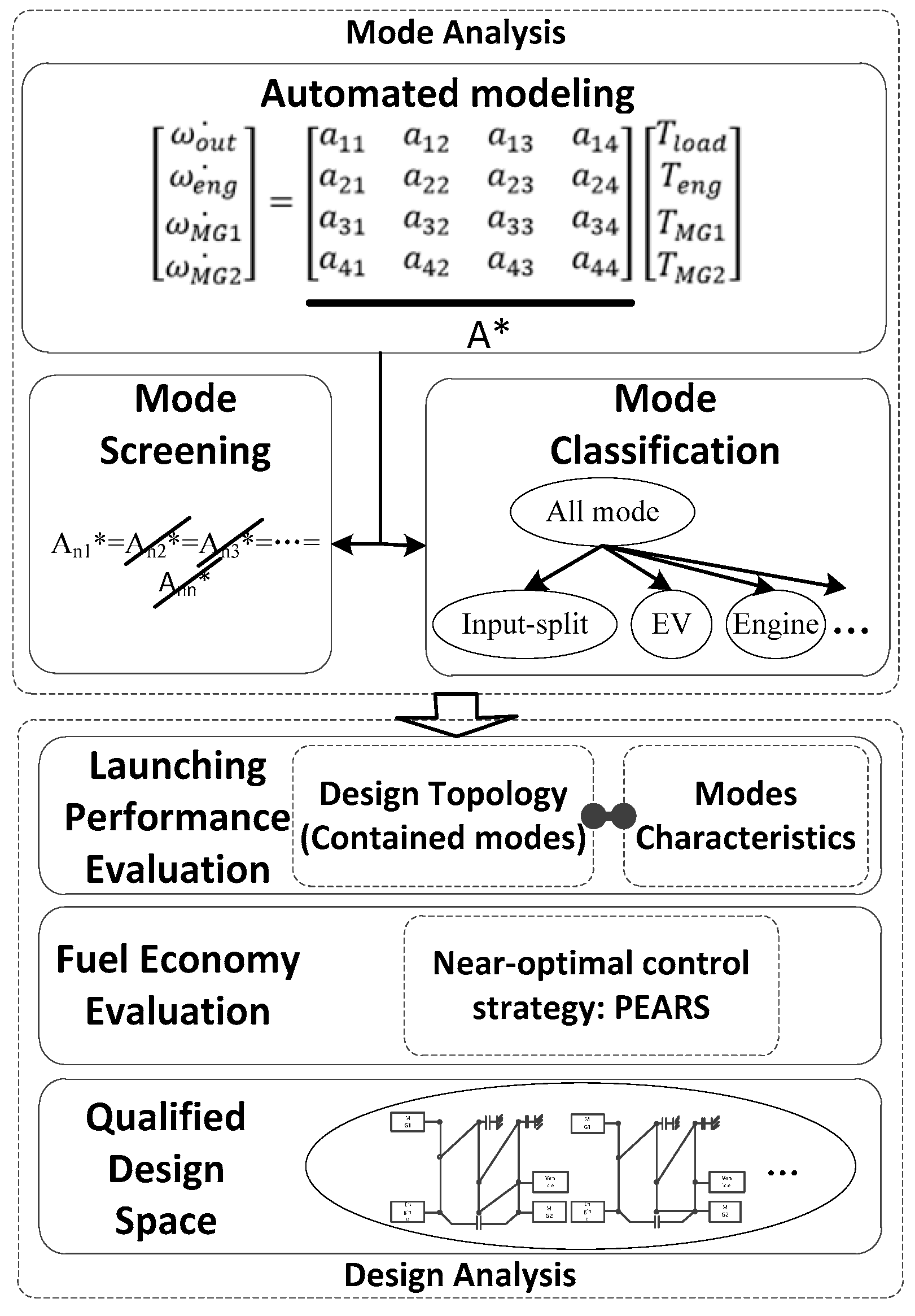
In addition to the vehicle dynamics and components’ models described above, we use a methodology, called automated modeling, to build up the power-split device models of different operating modes for the multi-mode HEV discussed in this paper [27]. In general, the dynamics of any specific mode is described by the characteristic matrix A*, as shown in Equation (3). This 4 × 4 characteristic matrix A* governs the relationship between the angular acceleration of powertrain devices and their corresponding torques. The detailed derivation can be found in [27].
[ ω out . ω eng . ω MG 1 . ω MG 2 . ] = A * [ T load T eng T MG 1 T MG 2 ] = [ a 11 a 12 a 13 a 14 a 21 a 22 a 23 a 24 a 31 a 32 a 31 a 34 a 41 a 42 a 43 a 44 ] [ T load T eng T MG 1 T MG 2 ]

2.3. Exhaustive Search

The exhaustive search approach has been used to explore all possible designs for optimal fuel economy and launching performance [27]. The flowchart of the exhaustive search is shown in Figure 2. With the automated modeling technology, the characteristic matrix A* which fully describes the dynamics of the system could be generated rapidly. Then, the modes that share the same characteristic matrix (i.e., identical modes) are identified, and only one of them is retained for subsequent analysis. In addition, all modes are classified into 14 different mode types based on their characteristics and functionalities. The criteria for the mode classification was proposed in [27]. After the mode analysis, winning designs are selected through a launching performance and fuel economy evaluation. Finally, a small pool of winning designs is obtained.

2.4. Case Study

In this paper, we apply the exhaustive search method introduced above to design a plug-in hybrid bus. The benchmark is a low floor hybrid bus by Gillig that uses the GM Allison Hybrid System (AHS) as the transmission. The parameters of this bus are shown in Table 1 [32,33].
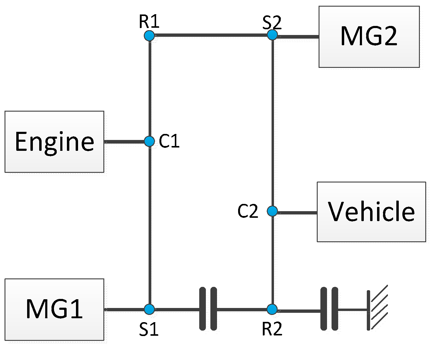
The AHS is a hybrid powertrain with two PGs and two clutches, and its lever diagram is depicted in Figure 3. By switching the states of these two clutches, an input-split mode and a compound split mode can be realized [3]. It should be noted that AHS does not contain a pure electric mode that may have a considerable effect on fuel economy, especially under a city driving cycle based on our previous study [14]. In this paper, we will also see the role of the electric mode for a hybrid electric bus.
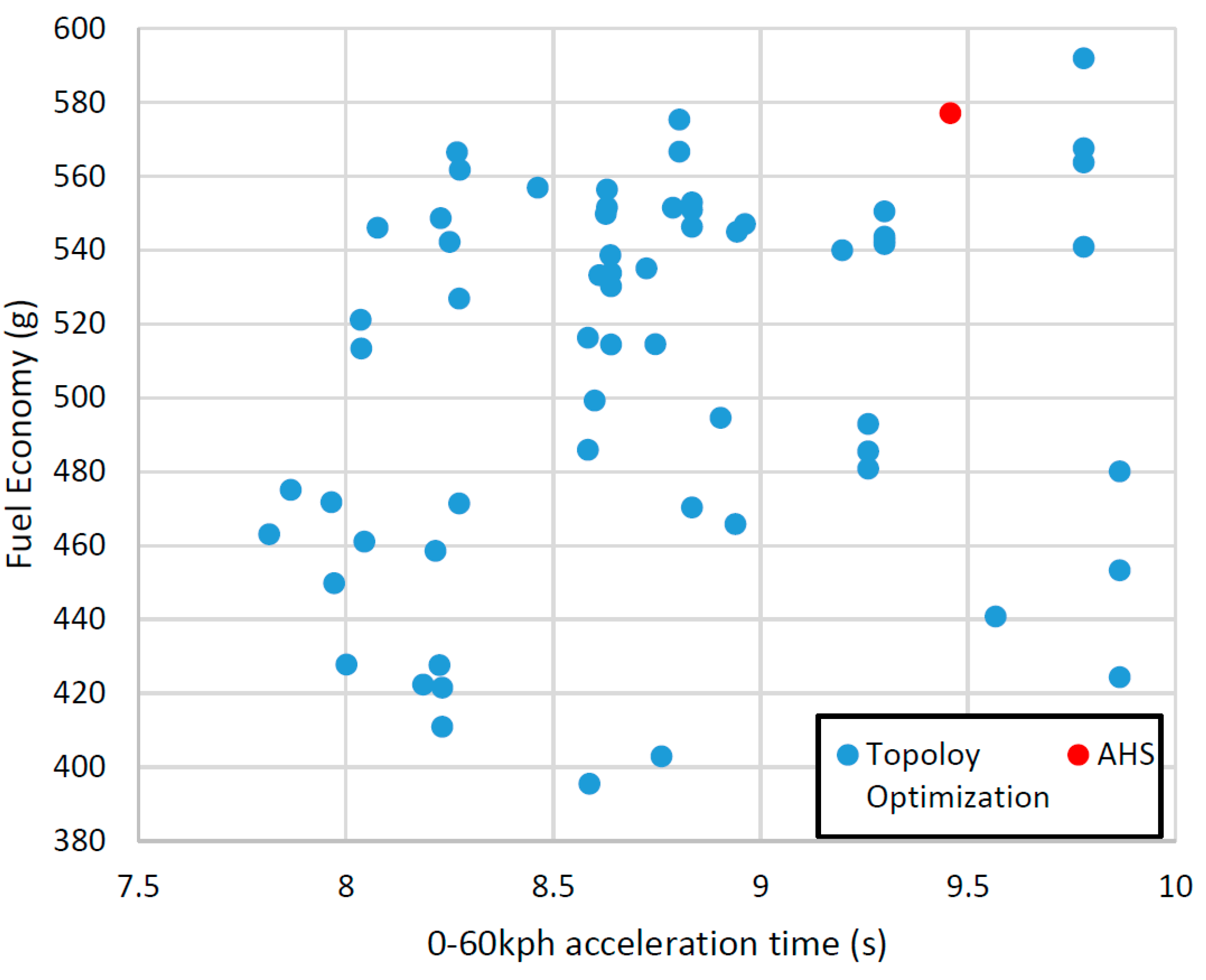
Figure 4 shows the topology optimization results of this plug-in hybrid bus, in which the red point shows the performance of the original benchmark plug-in hybrid bus and blue points are survived designs whose 0–60 kph acceleration is less than 10 s. The fuel consumption in the figure refers to the total fuel consumption calculated through a near-optimal control strategy, called PEARS, under the Manhattan driving cycle. A number of designs show significant improvement on both fuel economy and launching performance. The design with the best fuel economy consumes 395 g diesel for the cycle, nearly 31.5% better than the original AHS design. Up to this point, we only explored topology optimization. Component sizes can be manipulated for even better results but this design DoF has not been explored.

3. Optimal Design

The method introduced in Section II solved the optimal design problem without considering the component sizes, i.e., all powertrain parameters and component sizes are assumed to be given. In this section, we will introduce a methodology that combines the topology optimization and component sizing together to fully explore the fuel saving potential of hybrid electric bus.

3.1. Component Sizing

Powertrain component sizing consists of two groups: powertrain parameters, e.g., ring gear/sun gear ratio of the PGs, final drive ratio, etc.; and the component sizes, such as the motor power, engine power, and the energy storage capacity. In this paper, the engine is fixed. Only MG power and battery size are optimized.
The coupling between the energy management strategy and the component sizing, if fully considered, requires significant computational effort. Some researchers optimized the system with different hybridization ratios [21]. Others solved this problem heuristically, such as through GA and PSO [16,17]. In this paper, we adopt a two-loop optimization framework to solve this problem: the energy management strategy is optimized in the inner loop, while the outer loop solves optimal component sizes.
In the inner loop, the goal of the optimal energy management strategy is to minimize the cost function while avoiding frequent mode shift. The optimal control problem is defined in Equation (4) and is referred as Problem I:
Minimize:
J C ( u ( i ) | w ) = i = 0 t f f fuel ( i ) + i = 0 t f M o d e ( i ) + α ( S O C final S O C desired ) 2
Subject to:
{ S O C min S O C S O C max T e _ min T e T e _ max T MG 1 _ min T MG 1 T MG 1 _ max T MG 2 _ min T MG 2 T MG 2 _ max ω e _ min ω e ω e _ max ω MG 1 _ min ω MG 1 ω MG 1 _ max ω MG 2 _ min ω MG 2 ω MG 2 _ max M o d e M o d e available
where u(i) is the control variables for the multi-mode HEVs, w is the driving cycle characterized by slope, velocity and time. In the cost function, ffuel(i) is the fuel consumption, which is determined by the engine speed ωe, and engine torque Te. Mode(i) is the mode shift penalty:
M o d e ( i ) = β 1 [ ω e ( i + 1 ) ω e ( i ) ] 2 + β 2 [ ω MG 1 ( i + 1 ) ω MG 1 ( i ) ] 2 + β 3 [ ω MG 2 ( i + 1 ) ω MG 2 ( i ) ] 2
where ω * ( i ) and ω * ( i + 1 ) are the rotational speeds of the powertrain components at current time step and next step. β1, β2, β3 are the weighting factors to be tuned; the third term in the cost function is used to force the final battery state of charge SOCfinal back to its initial value SOCdesired; α is a large penalty factor to form an equality constraint of the final SOC. In addition, the torque and speed of the powertrain components are restricted by their operating constraints. The available modes Modeavailable for each specific design are different and dependent on the dynamics.
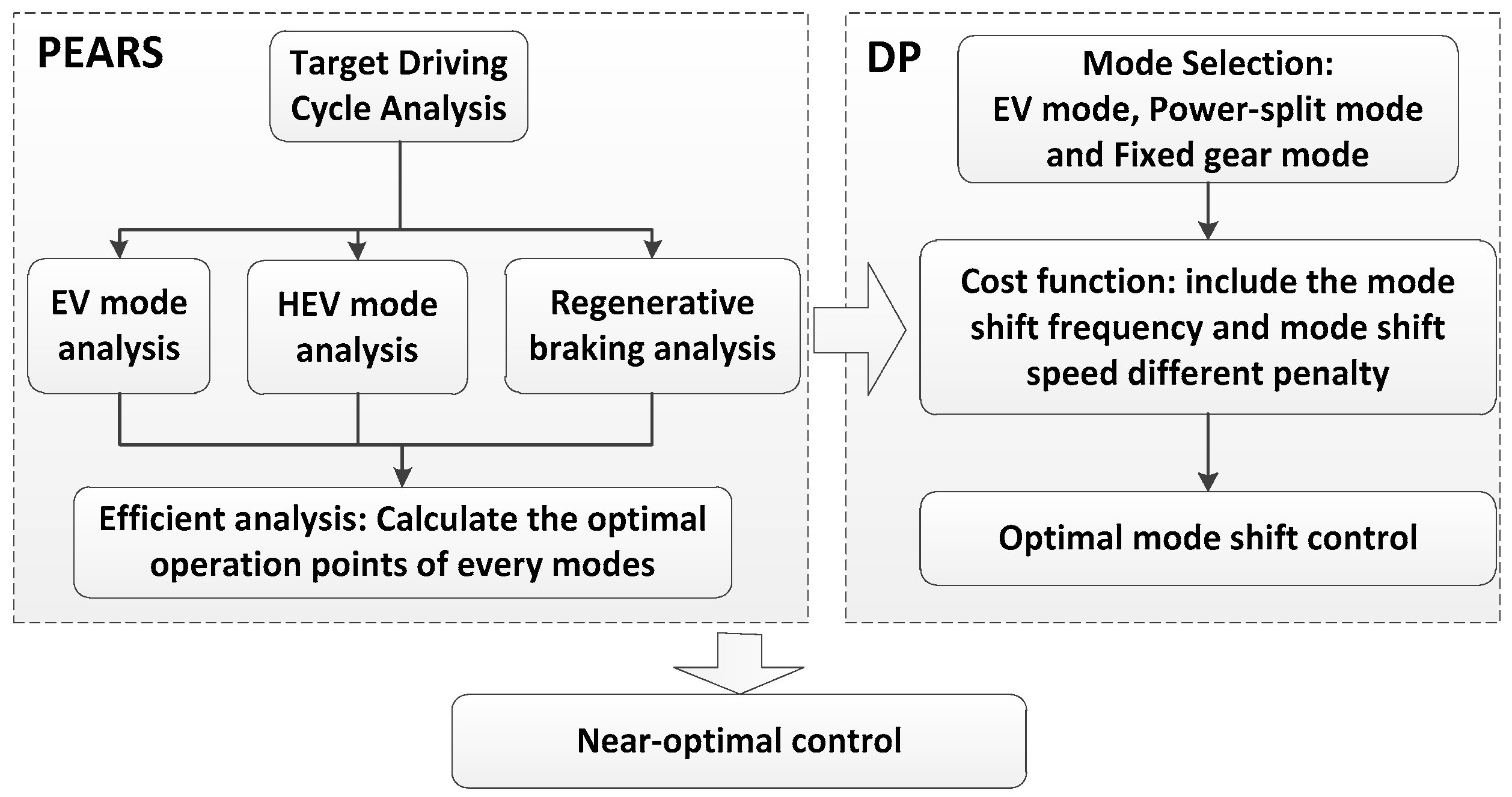
In this paper, this non-linear constrained optimization problem is solved recursively, and the limitation of popular energy management strategies are discussed in Section I. Therefore, we adopt the near-optimal control algorithm, called PEARS+, whose generated results are close DP, yet computationally more efficient [14]. The procedure of the PEARS+ is shown in Figure 5 [27,34].
In the outer-loop, the optimization of the component sizing, i.e., Problem II in Equation (6), is solved. The target in this step is to find the best powertrain parameters and sizes with minimum fuel consumption under the required vehicle performance constraints.
Minimize:
F ( x size = [ G PG 1 , G PG 2 , G FR , P MG 1 , P MG 2 , C Batt ] )
Subject to:
{ T acc ( x size ) T acc _ des θ max ( x size ) θ max _ des u max ( x size ) u max _ des
where the vector of the design variables xsize contains R/S ratio of two PGs GPG1, GPG2, the final drive ratio GFR, power of two MGs PMG1, PMG2 and the capacity of the battery CBatt. In addition, three constraints must be met: the minimum 0–60 kph acceleration time limit Tacc_des, the maximum gradeability limit θmax_des, which refers to the maximum road slope a vehicle can ascend while maintaining a particular speed and maximum vehicle speed limit umax_des. The solution of this problem will be explained in the next section.

3.2. Combined Optimization

In this section, two approaches are introduced to solve the combined problem of topology optimization and component sizing.

3.2.1. Nested Optimization (Approach I)

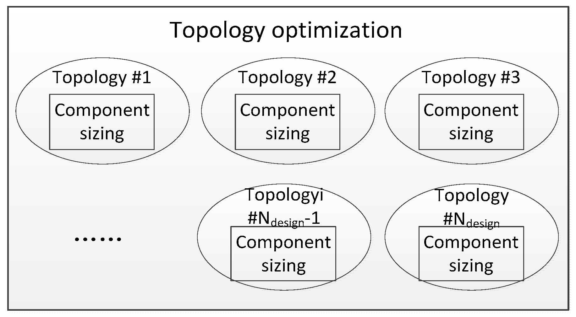
The first approach is called nested optimization where the component sizing is embedded within the topology optimization as shown in Figure 6.
Optimal component sizing is calculated in the lower level for each multi-mode hybrid powertrain design obtained at the upper level, and the design with best fuel economy is identified at the upper level. This approach is brute-force by nature. The formulation of this nested optimization problem is written below and referred to as Approach I:
Minimize:
G ( x top ,   x size ) ,   x top X top ,   x size X size
Subject to:
{ T acc ( x top , x size ) T acc _ des θ max ( x top , x size ) θ max _ des u max ( x top , x size ) u max _ des x size arg min { F ( x top , y size ) : h ( x top , y size ) 0 , y size X size , j { 1 , 2 , , J } }
where G represents the objective function of the upper level (topology optimization), F represents the objective function of the lower level (component sizing) and h is the set of inequality constraints at the lower level. xcon is the parameters that contains the powertrain locations L pow ¯ , clutch locations L clu ¯ , and permanent connection locations L per ¯ . In addition, vehicles should meet three vehicle performance requirements in launching, climbing, and top speed.

3.2.2. Iterative Optimization (Approach II)

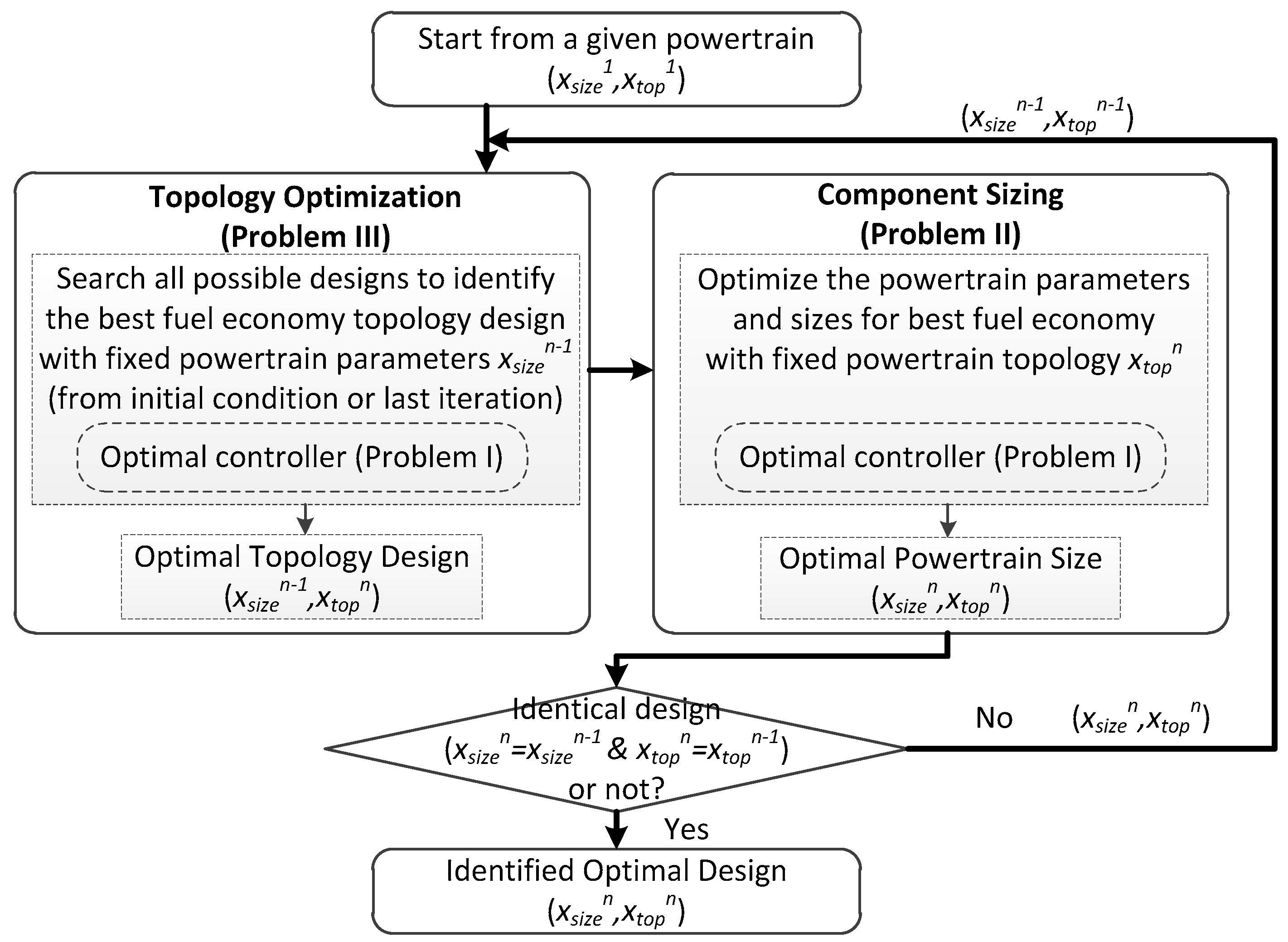
The second approach is called iterative optimization, where the topology optimization and component sizing is executed sequentially and iteratively until convergence. Its process is described in Figure 7.
The topology optimization problem is formulated in Equation (8) and referred to as Problem III, in which the goal is to identify the best fuel economy design under the same performance constraints as in Problem II:
Minimize:
G ( x top = [ L pow ¯ , L clu ¯ , L per ¯ ] )
Subject to:
{ T acc ( x top ) T acc _ des θ max ( x top ) θ max _ des u max ( x top ) u max _ des
where xtop is a vector to represent each possible hybrid design with assigned powertrain locations L pow ¯ , clutch locations L clu ¯ , and permanent connection locations L per ¯ .
As shown in Figure 7, the loop starts from any given powertrain (xsize, xtop) that the powertrain parameters, component sizes and powertrain topology are all known, e.g., the hybrid bus as shown in Table 1, and the powertrain design from the last iteration (xsizen−1, xtopn−1). In the first step of each iteration, the powertrain topology is optimized with powertrain parameters xsizen−1. In the second step, the optimal powertrain parameters of the optimal topology design derived in the first step are identified by solving Problem II. Afterwards in the third step, the identified powertrain topology with optimal parameters in the second step (xsizen−1, xtopn−1) is compared with the powertrain at the beginning of this iteration (xsizen, xtopn). If the powertrains are the same, referring to identical powertrain topology and parameters, we denote it as the optimal topology and the optimal sizing parameters. If not, the identified powertrain (xsizen, xtopn) requires the topology optimization and component sizing to sequentially check its optimality by comparing the powertrains at the beginning and end of each iteration. The iteration stops when the solution converges. At the end, a new hybrid design with both optimized topology and component sizes is identified.

3.3. Results

The two approaches proposed in Section 3.2 are applied to find optimal designs for a hybrid bus. The parameters described in Table 1 are used as the initial values. The nested optimization solution is taken as the benchmark to check the optimality of the iterative optimization approach. Note that some of the vehicle parameters (i.e., mass, frontal area, aero drag coefficient, rolling resistance, and tire radius) are fixed. As introduced in Section II, the number of possible powertrain designs with three clutches is 2,620,800. If all powertrain parameters (R/S ratios, final drive ratio, motor sizes, and battery size) are divided into ten grids equally, we need to solve the optimal energy management problem 2.6 × 10¹² times for the nested optimization platform, which takes a very long time to solve. For simplicity, several assumptions are made to define a simpler problem that can be solved in a reasonable amount of time.
(1)
We fixed the powertrain component locations the same as what was shown in Figure 3.
(2)
We only optimize the powertrain parameters (i.e., R/S ratio of PGs and final drive) in this study.
The grids and range for the ratio of PGs and final drive is listed as follows:
{ G PG 1 = G PG 2 = [ 1.2 : 0.2 : 3 ] G FR = [ 3 : 0.5 : 9 ]
With the above assumptions and definitions, the number of designs is three orders of magnitude smaller:
N design ' = N design × 10 × 10 × 13 = 3.4 × 10 9
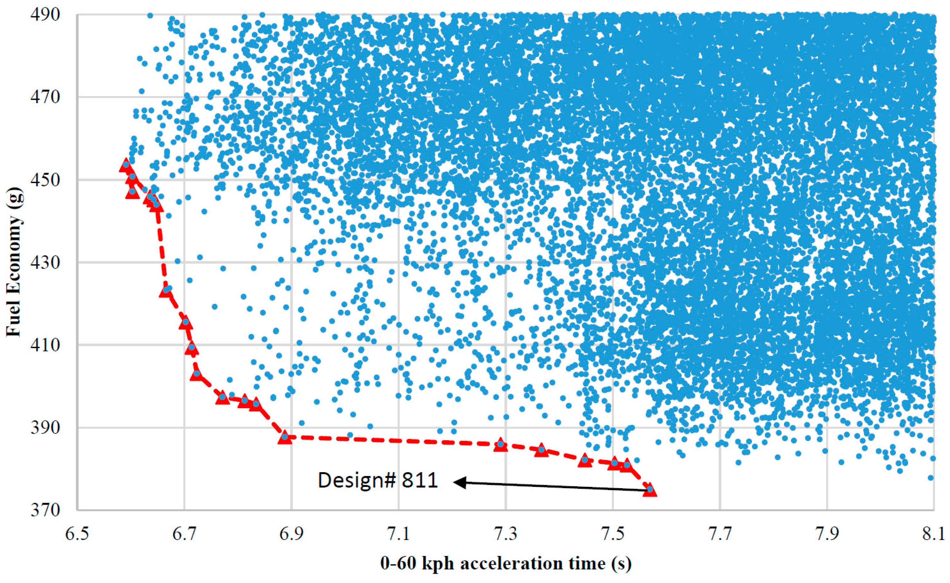
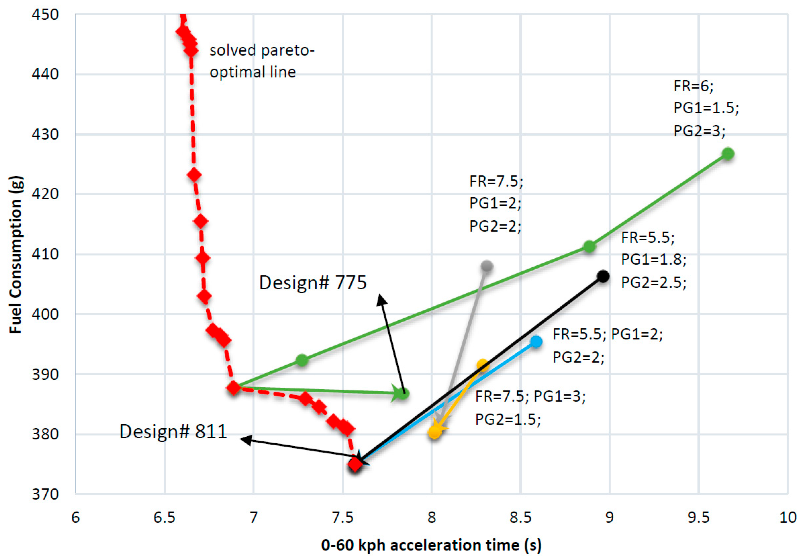
Figure 8 shows the results of nested optimization, where the red triangles form the Pareto front and the X and Y axes stand for the acceleration and fuel economy performance, respectively. Design number refers to a specific design labeled before the optimization. Compared with the original AHS hybrid powertrain, Design 811 has 35.0% and 19.7% improvement on fuel economy and acceleration performance. In addition, we listed the results with only component sizing optimization and topology optimization in Table 2. It can be seen that the design with both component sizing and topology optimized achieves greater improvement than designs when only the topology or component sizing is optimized. Meanwhile, designs obtained with topology optimization perform better than the designs with only component sizing optimization. In other words, topology optimization is a more effective design exploration than tuning component sizes.
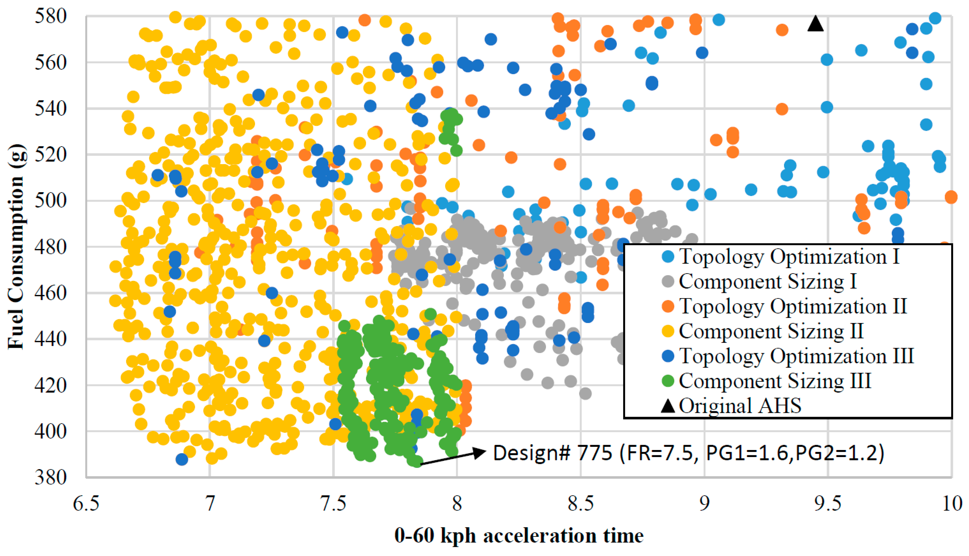
Table 3 and Figure 9 show the optimization results of each iteration for the case study whose initial powertrain parameters, final drive, R/S ratios of two PGs equal to 6, 1.5 and 3, respectively. In Figure 9, colors indicate the performance of all possible designs for different iterations. As shown, a better design with different topologies or powertrain parameters is identified for each step until the end of the third component sizing (component sizing of Iteration III). One more iteration (Iteration IV) is executed to check the optimality of the resulted design at the end of Iteration III.
The optimal designs of each iteration are extracted and plotted in Figure 10 to demonstrate the trend of the optimization. Four other cases with different initial conditions are also plotted in Figure 10, where the red dashed line is the fitted Pareto front from nested optimization. They all converge toward the bottom left corner. It can be seen that black and blue lines are converging to the global optimal design, Design 811, after only two iterations. Gray and yellow lines are also converging within only two iterations, but they do not converge to the global optimal design.
In summary, the iterative optimization process successfully converges to the global optimal design that is obtained from nested optimization in last case study. In the meantime, instead of calculating the fuel economy of all 3.4 × 10⁹ designs, as discussed in Equation (8), the iterative optimization only takes a few iterations (examining about 2500 designs in each iteration) to converge to an optimized design. Thus, the computation time is much shorter than exhaustive search. However, the iterative optimization approach is sensitive to the initial conditions (i.e., powertrain parameters). In the next section, we will propose a method to enhance the iterative optimization approach and reduce of its reliance to initial conditions.

3.4. Enhanced Iterative Optimization

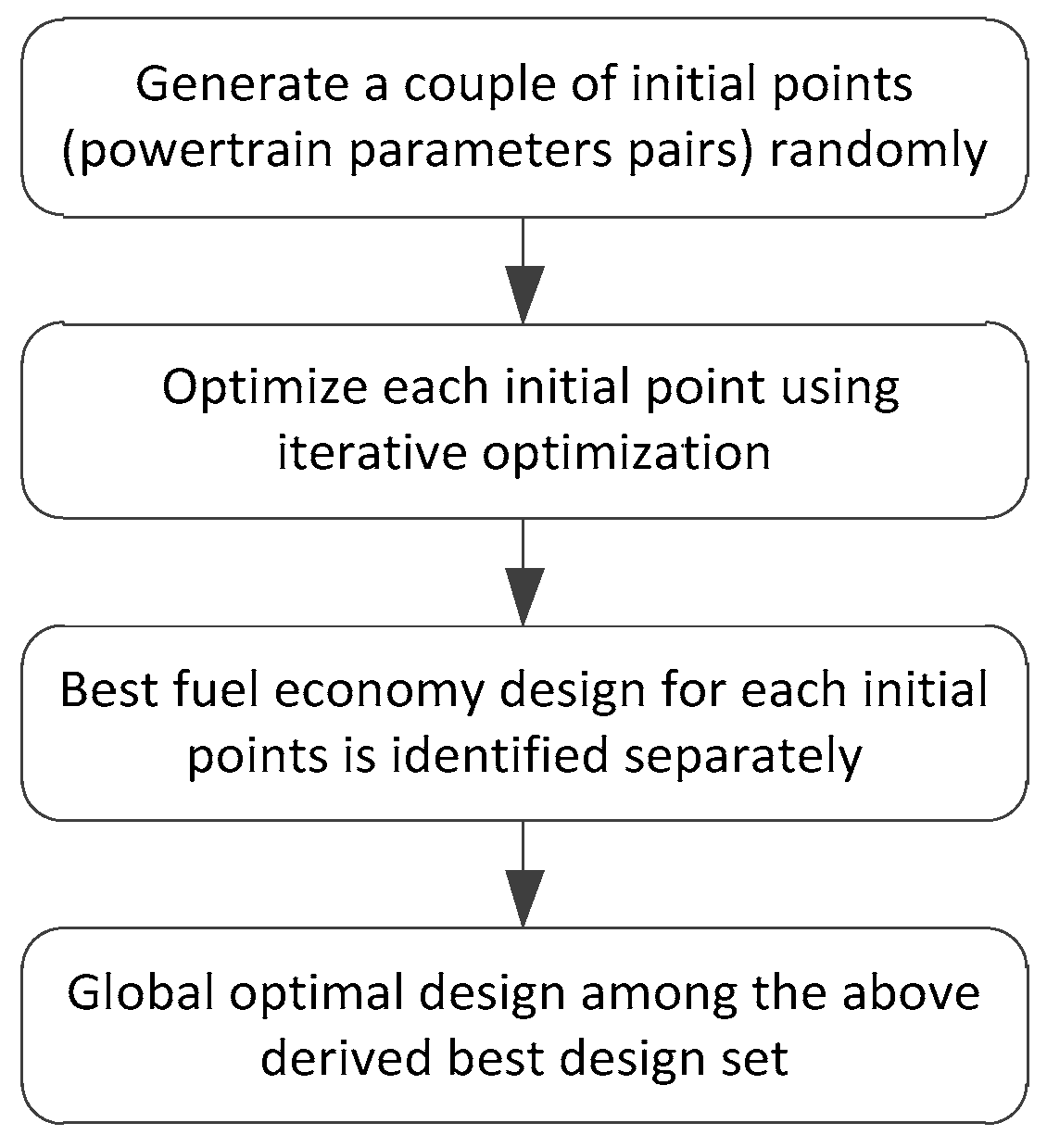
To overcome the sensitivity problem of the iterative optimization, a method, called enhanced iterative optimization is proposed in this part. The process of this method is presented in Figure 11. The optimization starts from a couple of random initial points. For each point, we can identify the best fuel economy design using the iterative optimization. Then, we search the design with minimum fuel consumption among the group of identified designs. In this way, the impact of the initial conditions on the final results can be reduced, while the computational efficiency is still much better than the nested optimization. In summary, Table 4 shows the performance comparison between the three approaches proposed in this paper, where mi represents the number of initial conditions used for computation. Enhanced iterative optimization indicates better convergence performance than iterative optimization and is more efficient than nested optimization.

4. Payload Sensitivity Study

Many optimal sizing studies identify optimal designs for given driving cycles and some of the vehicle parameters are fixed [35]. The resulting design may be sensitive to vehicle parameter variations, such as the vehicle weight, a parameter that changes significantly (and even more for heavy trucks). A topology optimized for a specific weight may not work well when the vehicle weight changes. In this section, we apply the enhanced iterative optimization method to optimize the topology and powertrain parameters of a vehicle for fuel economy with frequently changed weight.
We assume the average passenger weight is 80 kg and the capacity of the bus is 50 persons [36], so the mass of the fully loaded bus is 13,380 + 4000 kg. In this section, we evaluate six different cases with the payload increasing in steps of 800 kg. All six cases are assumed to be equally important in the final cost function calculation. The performance requirement is defined as following: the bus needs to achieve a top speed of 100 kph and can climb a 25% slope. In addition, the minimum acceleration time of 0–60 kph should be less than 10 s at all loading conditions.
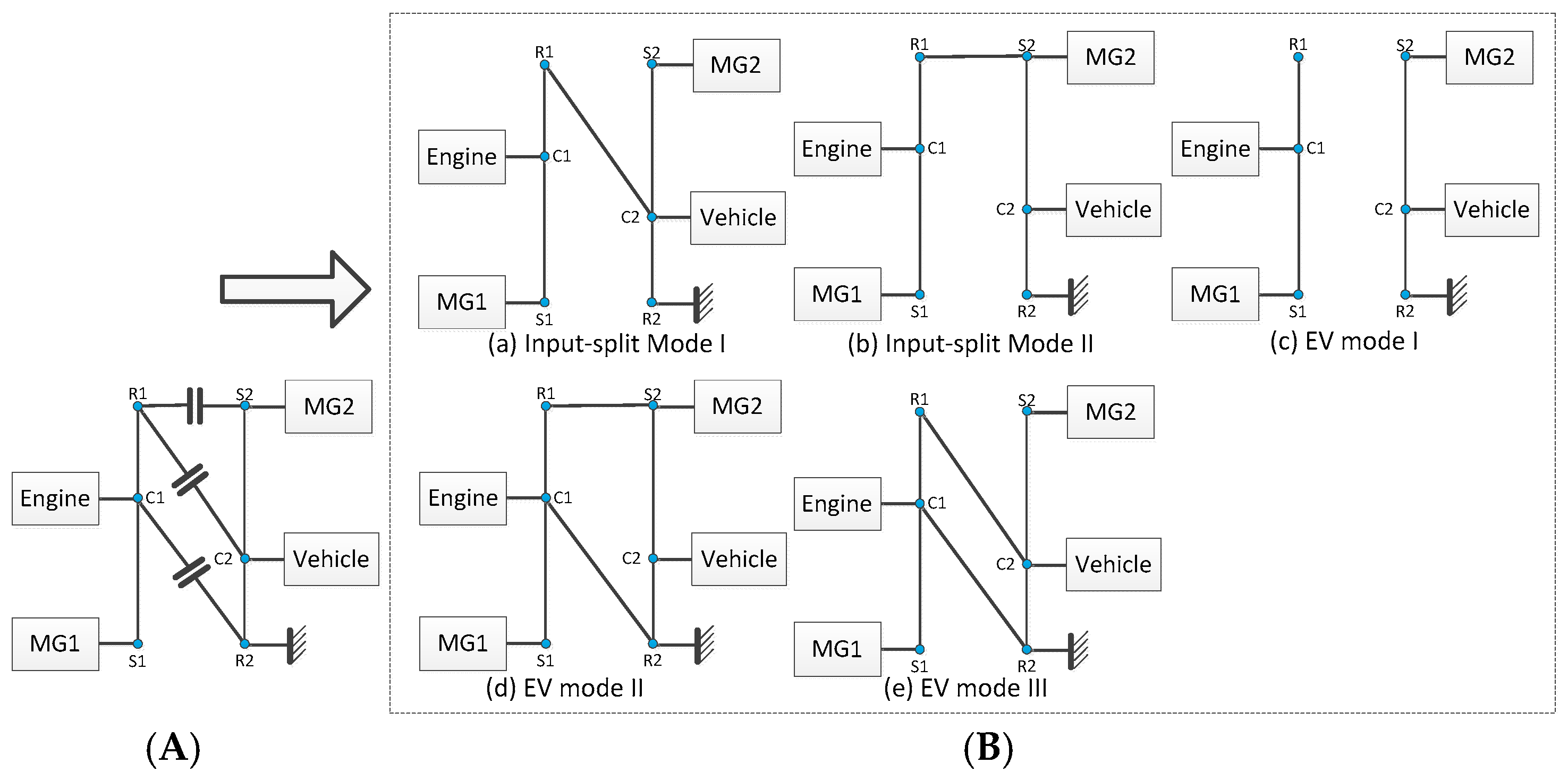
Under these conditions, we optimize the topologies and powertrain parameters of the bus for the Manhattan driving cycle using the iterative optimization method. The optimal topology and powertrain parameters are listed in Table 5 where Design 811 is the best design topology for all six scenarios as shown in Figure 12A. As we can see, all loading conditions have the same optimal power-split configuration but the optimal parameters are different.
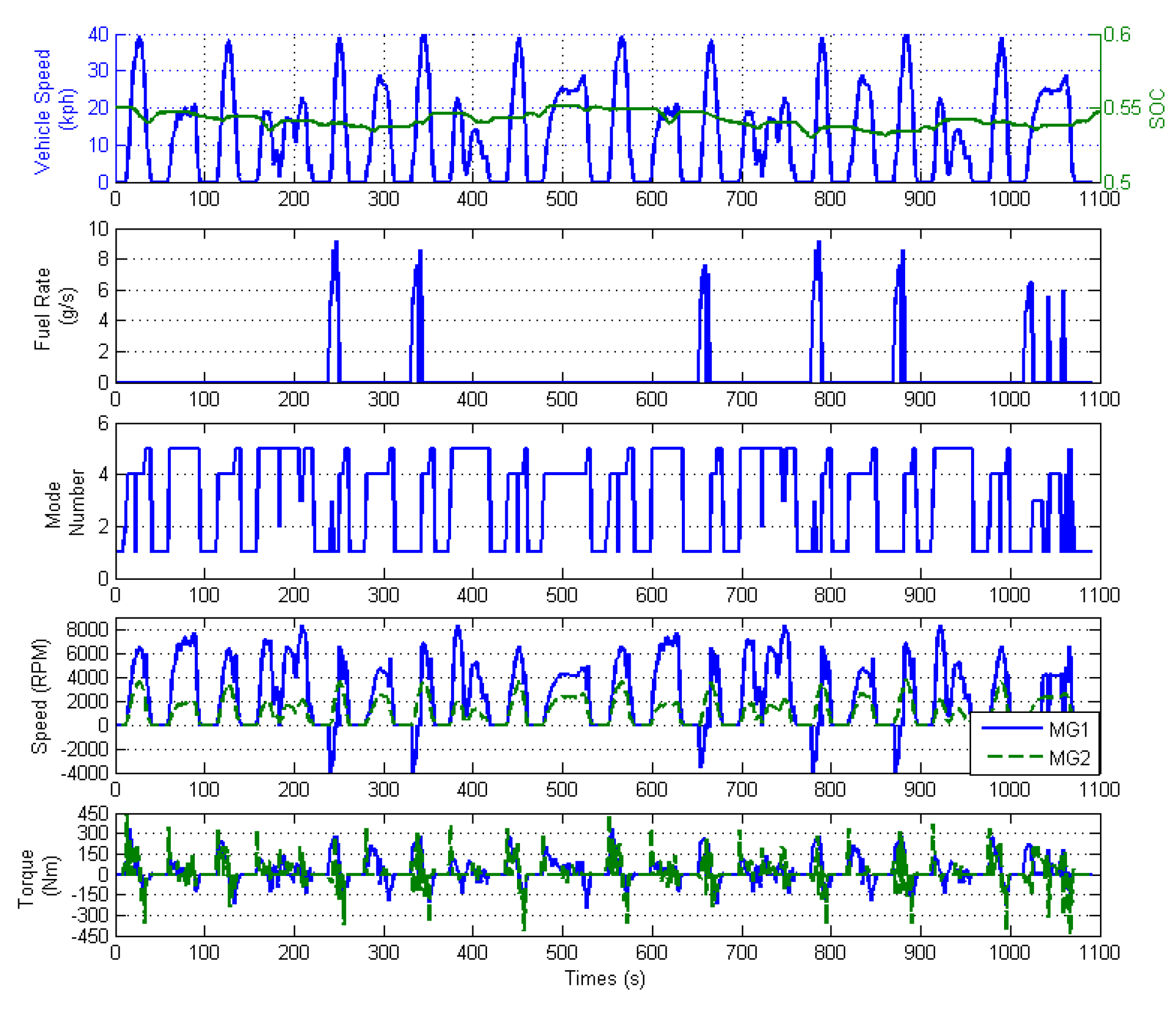
In order to obtain the best design under all conditions, we use the overall fuel consumption under the six payload scenarios as the cost function. The topology of the optimal design, Design 811, is shown in Figure 12. It has five operating modes—two input-split modes and three electric drive modes, also shown in Figure 12. The optimal parameters for the R/S ratios of PG1, PG2, and final drive are 2.8, 1.2, and 8, respectively. The state and control trajectories of this optimal powertrain is shown in Figure 13 where mode number 1–5 stands for input-split mode I, EV mode I, input-split mode II, EV mode II, and EV mode III. As we can see, EV modes are widely used for low-speed range and regenerative braking. That is the reason Design 811 shows better fuel economy than the original AHS. It indicates that pure electric driving modes are also essential for hybrid buses more than plug-in HEVs.
It should be noted that the battery capacity for a hybrid bus is also important but is largely dependent on the trade-off between electric range and cost. Therefore, it is not included in this large-scale design study. We will consider this factor in the future.

5. Conclusions

The contribution of this paper is three-fold. Firstly, we optimize the multi-mode hybrid powertrain from three dimensions, i.e., exploring the topologies of a power-split hybrid powertrain with double PGs and clutches, optimizing powertrain parameters, and realizing optimal control of the power split between the fuel and electricity. These three aspects are coupled together by developing an optimization framework, called iterative optimization. Instead of searching the whole design space (referred as nested optimization), iterative optimization executes topology optimization and component sizing alternately. A case study shows that iterative optimization converges to the global optimal design efficiently. Secondly, we present an enhanced iterative optimization framework to alleviate the sensitivity problem of the initial conditions. Thirdly, we develop a robust multi-mode hybrid electric bus considering a variety of loading scenarios by using the proposed enhanced iterative optimization. The resulting hybrid bus achieves better fuel economy by introducing EV modes under the Manhattan driving cycle.
In this paper, we search the optimal component size through an exhaustive search, which may be impractical if more parameters are taken into consideration in the future due to the computational burden. Instead, other heuristic methods, like GA and PSO, can be adopted to optimize the component sizes to accelerate the calculation.

Acknowledgments

This work was supported by Jiangsu Science and Technology Agency under Joint Innovation Funding (BY2014004-04 and BY2015004-02).

Author Contributions

Weichao Zhuang proposed the optimization framework and adopted it to optimize a hybrid electric bus, Xiaowu Zhang, Huei Peng and Liangmo Wang provided guidance and key suggestions.

Conflicts of Interest

The authors declare no conflict of interest.

References

  1. National Highway Traffic Safety Administration (NHTSA). Obama Administration Finalizes Historic 54.5 mpg Fuel Efficiency Standards. Available online: http://www.nhtsa.gov/About+NHTSA/Press+Releases/2012/Obama+Administration+Finalizes+Historic+54.5+mpg+Fuel+Efficiency+Standards (accessed on 25 December 2015).
  2. Alternative Fuels Data Center: Maps and Data. U.S. HEV Sales by Model. 2014. Available online: http://www.afdc.energy.gov/data/10301 (accessed on 25 December 2015). [Google Scholar]
  3. Miller, J.M. Hybrid electric vehicle propulsion system architectures of the e-CVT type. IEEE Trans. Power Electron. 2006, 21, 756–767. [Google Scholar] [CrossRef]
  4. Zhang, X.W.; Li, C.T.; Kum, D.; Peng, H. Prius+ and Volt: Configuration analysis of power-split hybrid vehicles with a single planetary gear. IEEE Trans. Veh. Technol. 2012, 61, 3544–3552. [Google Scholar] [CrossRef]
  5. Xu, L.F.; Ouyang, M.G.; Li, J.Q.; Yang, F.Y.; Lu, L.G.; Hua, J.F. Optimal sizing of plug-in fuel cell electric vehicles using models of vehicle performance and system cost. Appl. Energy 2013, 103, 477–487. [Google Scholar] [CrossRef]
  6. Jalil, N.; Kheir, N.; Salman, M. A Rule-Based Energy Management Strategy for a Series Hybrid Vehicle. In Proceedings of the 1997 American Control Conference, Albuquerque, NM, USA, 4–6 June 1997; pp. 689–693.
  7. Musardo, C.; Rizzoni, G.; Guezennec, Y.; Staccia, B. A-ECMS: An adaptive algorithm for hybrid electric vehicle energy management. Eur. J. Control 2005, 11, 509–524. [Google Scholar] [CrossRef]
  8. Sciarretta, A.; Back, M.; Guzzella, L. Optimal control of parallel hybrid electric vehicles. IEEE Trans. Control Syst. Technol. 2004, 12, 352–363. [Google Scholar] [CrossRef]
  9. Lin, C.C.; Peng, H.; Grizzle, J.W.; Kang, J.-M. Power management strategy for a parallel hybrid electric truck. IEEE Trans. Control Syst. Technol. 2003, 11, 839–849. [Google Scholar]
  10. Larsson, V.; Lars, J.; Egardt, B. Analytic solutions to the dynamic programming subproblem in hybrid vehicle energy management. IEEE Trans. Veh. Technol. 2015, 64, 1458–1467. [Google Scholar] [CrossRef]
  11. Vinot, E. Time Reduction of the Dynamic Programming Computation in the Case of Hybrid Vehicle. In Proceedings of the 13th International Workshop on OIPE 2014—Optimization and Inverse Problems in Electromagnetism, Delft, The Netherlands, 10–12 September 2014.
  12. Hu, X.; Murgovski, N.; Johannesson, L.M.; Egardt, B. Optimal dimensioning and power management of a fuel cell/battery hybrid bus via convex programming. IEEE/ASME Trans. Mechatron. 2015, 20, 457–468. [Google Scholar] [CrossRef]
  13. Nüesch, T.; Elbert, P.; Flankl, M.; Onder, C.; Guzzella, L. Convex optimization for the energy management of hybrid electric vehicles considering engine start and gearshift costs. Energies 2014, 7, 834–856. [Google Scholar] [CrossRef]
  14. Zhang, X.; Peng, H.; Sun, J. A near-optimal power management strategy for rapid component sizing of multimode power split hybrid vehicles. IEEE Trans. Control Syst. Technol. 2015, 23, 609–618. [Google Scholar] [CrossRef]
  15. Zou, Y.; Li, D.G.; Hu, X.S. Optimal sizing and control strategy design for heavy hybrid electric truck. Math. Probl. Eng. 2012, 2012. [Google Scholar] [CrossRef]
  16. Fang, L.C.; Qin, S.Y.; Xu, G.; Li, T.L.; Zhu, K.M. Simultaneous optimization for hybrid electric vehicle parameters based on multi-objective genetic algorithms. Energies 2011, 4, 532–544. [Google Scholar] [CrossRef]
  17. Ebbesen, S.; Doenitz, C.; Guzzella, L. Particle swarm optimisation for hybrid electric drive-train sizing. Int. J. Veh. Des. 2012, 58, 181–199. [Google Scholar] [CrossRef]
  18. Wu, L.H.; Wang, Y.N.; Yuan, X.F.; Chen, Z.L. Multiobjective optimization of HEV fuel economy and emissions using the self-adaptive differential evolution algorithm. IEEE Trans. Veh. Technol. 2011, 60, 2458–2470. [Google Scholar] [CrossRef]
  19. Shankar, R.; Marco, J.; Assadian, F. The novel application of optimization and charge blended energy management control for component downsizing within a plug-in hybrid electric vehicle. Energies 2012, 5, 4892–4923. [Google Scholar] [CrossRef]
  20. Murgovski, N.; Johannesson, L.; Sjoberg, J.; Egardt, B. Component sizing of a plug-in hybrid electric powertrain via convex optimization. Mechatronics 2012, 22, 106–120. [Google Scholar] [CrossRef]
  21. Sundström, O.; Guzzella, L.; Soltic, P. Torque-assist hybrid electric powertrain sizing: From optimal control towards a sizing law. IEEE Trans. Control Syst. Technol. 2010, 18, 837–849. [Google Scholar] [CrossRef]
  22. Nuesch, T.; Ott, T.; Ebbesen, S.; Guzzella, L. Cost and Fuel-Optimal Selection of HEV Topologies Using Particle Swarm Optimization and Dynamic Programming. In Proceedings of the 2012 American Control Conference (ACC), Montreal, QC, Canada, 27–29 June 2012; pp. 1302–1307.
  23. Zhang, X.W.; Peng, H.; Sun, J. A Near-Optimal Power Management Strategy for Rapid Component Sizing of Power Split Hybrid Vehicles with Multiple Operating Modes. In Proceedings of the 2013 American Control Conference (ACC), Washington, DC, USA, 17–19 June 2013; pp. 5972–5977.
  24. Liu, J.M.; Peng, H. A systematic design approach for two planetary gear split hybrid vehicles. Veh. Syst. Dyn. 2010, 48, 1395–1412. [Google Scholar] [CrossRef]
  25. Bayrak, A.E.; Ren, Y.; Papalambros, P.Y. Design of Hybrid-Electric Vehicle Architectures Using Auto-Generation of Feasible Driving Modes. In Proceedings of the ASME 2013 International Design Engineering Technical Conferences and Computers and Information in Engineering Conference: American Society of Mechanical Engineers, Portland, OR, USA, 4–7 August 2013; p. V001T01A005.
  26. Kang, M.; Kim, H.; Kum, D. Systematic Configuration Selection Methodology of Power-Split Hybrid Electric Vehicles with a Single Planetary Gear. In Proceedings of the ASME 2014 Dynamic Systems and Control Conference: American Society of Mechanical Engineers, San Antonio, TX, USA, 22–24 October 2014; p. V001T15A001.
  27. Zhang, X.; Li, S.; Peng, H.; Sun, J. Efficient exhaustive search of power split hybrid powertrains with multiple planetary gears and clutches. J. Dyn. Sys. Meas. Control 2015, 137. [Google Scholar] [CrossRef]
  28. Silvas, E.; Hofman, T.; Serebrenik, A.; Steinbuch, M. Functional and cost-based automatic generator for hybrid vehicles topologies. IEEE/ASME Trans. Mechatron. 2015, 20, 1561–1572. [Google Scholar] [CrossRef]
  29. Klemen, D.; Schmidt, M.R. Two-Mode, Compound-Split, Electro-Mechanical Vehicular Transmission Having Significantly Reduced Vibrations. U.S. Patent 6,358,173, 19 March 2002. [Google Scholar]
  30. Holmes, A.G.; Schmidt, M.R. Hybrid Electric Powertrain Including a Two-Mode Electrically Variable Transmission. U.S. Patent 6,478,705, 12 November 2002. [Google Scholar]
  31. Conlon, B.M.; Blohm, T.; Harpster, M.; Holmes, A.; Palardy, M.; Tarnowsky, S. The next generation “Voltec” extended range EV propulsion system. SAE Int. J. Altern. Powertrains 2015, 4, 248–259. [Google Scholar] [CrossRef]
  32. Hallmark, S.; Wang, B.; Qiu, Y.; Sperry, R. Evaluation of In-Use Fuel Economy for Hybrid and Regular Transit Buses. J. Transp. Technol. 2013, 3, 52–57. [Google Scholar] [CrossRef]
  33. Allison Hybrid H40 EP/H50 EP. Available online: http://www.allisontransmission.com/docs/default-source/marketing-materials/sa5983en-h40-50-ep1BCB31AC06C2F2B94ACCEED0.pdf?sfvrsn=4 (accessed on 25 December 2015).
  34. Zhuang, W.; Zhang, X.; Zhao, D.; Peng, H.; Wang, L. Optimal design of three-planetary-gear power-split hybrid powertrains. Int. J. Automot. Technol. 2016, 17, 299–309. [Google Scholar] [CrossRef]
  35. Bayrak, A.E.; Ren, Y.; Papalambros, P.Y. Optimal Dual-Mode Hybrid Electric Vehicle Powertrain Architecture Design for a Variety of Loading Scenarios. In Proceedings of the ASME 2014 International Design Engineering Technical Conferences and Computers and Information in Engineering Conference: American Society of Mechanical Engineers, Buffalo, NY, USA, 17–20 August 2014; p. V003T01A005.
  36. Mendes, E. In U.S., Self-Reported Weight Up Nearly 20 Pounds Since 1990. Available online: http://www.gallup.com/poll/150947/self-reported-weight-nearly-pounds-1990.aspx (accessed on 25 December 2015).
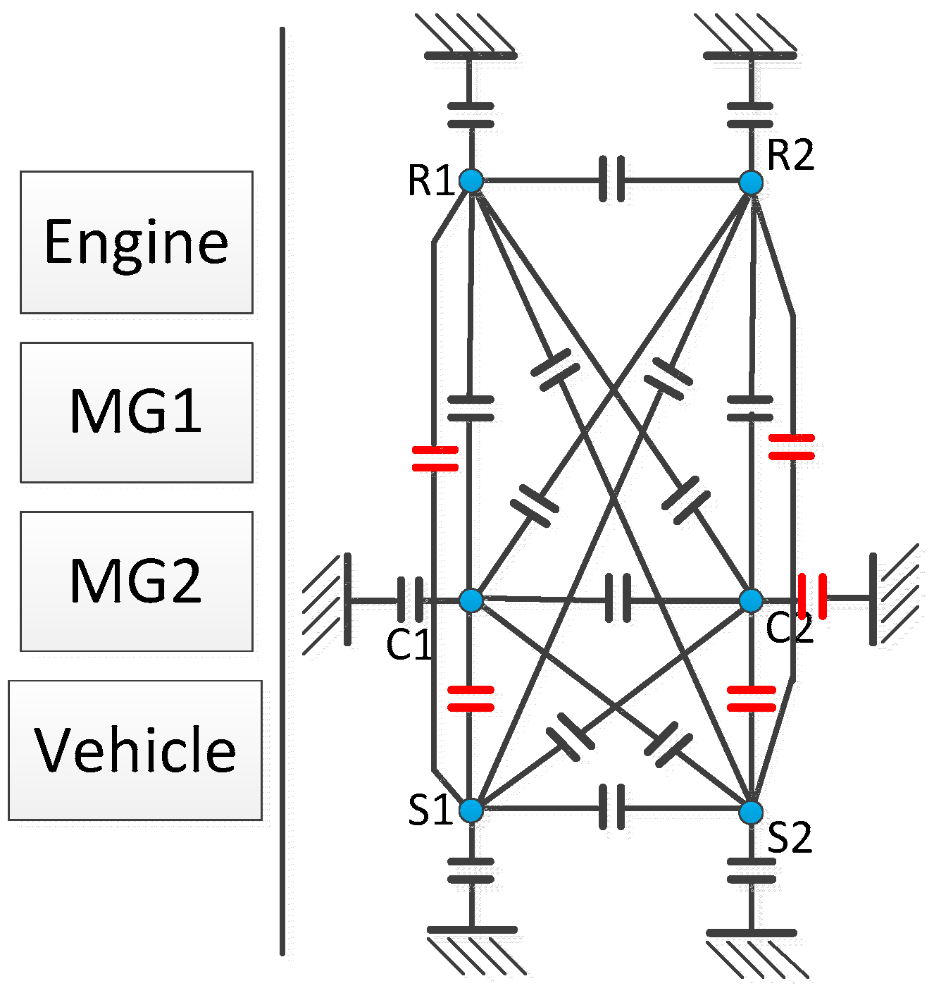
Figure 1. Powertrain components of power-split hybrid electric vehicle (HEV) and all possible clutch locations for a double planetary gear (PG) hybrid.
Energies 09 00411 g001
Figure 2. The proposed process for exhaustive topology search. PEARS: power-weighted efficiency analysis for rapid sizing.
Energies 09 00411 g002
Figure 3. Lever diagram of the AHS.
Energies 09 00411 g003
Figure 4. Fuel consumption and launching performance of survived designs and AHS hybrid.
Energies 09 00411 g004
Figure 5. Procedure of the near-optimal control PEARS+.
Energies 09 00411 g005
Figure 6. Schematic diagram of the nested optimization.
Energies 09 00411 g006
Figure 7. Flow chart of the iterative optimization.
Energies 09 00411 g007
Figure 8. Results of nested optimization where red line is the Pareto-optimal.
Energies 09 00411 g008
Figure 9. Results of each optimization for initial point (FR = 6, PG1 = 1.5, PG2 = 3).
Energies 09 00411 g009
Figure 10. Sample results from iterative optimization.
Energies 09 00411 g010
Figure 11. Process of the proposed enhanced iterative optimization.
Energies 09 00411 g011
Figure 12. Identified optimal powertrain design for the target bus application and its operating modes (A) lever diagram of the Design 811; and (B) operating modes of the optimal powertrain Design 811.
Energies 09 00411 g012
Figure 13. State and control trajectories of the simulated optimal powertrain design under the Manhattan cycle by near-optimal control strategy PEARS+.
Energies 09 00411 g013
Table 1. Parameters of a Gillig plug-in hybrid electric bus with the Allison Hybrid System (AHS) powertrain [30]. PG: planetary gear.
ComponentParameterValue
EngineDisplacementCummins ISB 280 6.7 L
Maximum Power209 kW @ 1600 RPM
Maximum Torque895 Nm @ 1600 RPM
Inertia0.82 kg·m2
MG1, MG2Maximum Power80 kW
Maximum Torque450 Nm
Maximum Speed9600 RPM
LiFePO4 batteryMaximum Power60 Ah
Voltage900 V
All PGRing/Sun ratio2
Final DriveGear Ratio5.38
VehicleMass13,380 kg
Frontal area9.5 m2
Aero drag coefficient0.62
Rolling Resistance0.015
Tire radius0.51 m
Table 2. Performance improvement of the hybrid bus before and after nested optimization.
Optimization MethodFuel ConsumptionAcceleration Time
Value (g)Improvement (%)Value (s)Improvement (%)
Original AHS577N/A9.45N/A
Component sizing optimization only471.3418.4%8.767.3%
Topology optimization only395.4531.5%8.589.2%
Both component sizing and topology optimization375.035.0%7.5719.7%
Table 3. Optimal results of each iteration for initial point (FR = 6, PG1 = 1.5, PG2 = 3).
IterationOptimizationOptimal TopologyPG1 R/S RatioPG2 R/S RatioFinal Drive RatioAcceleration Time (s)Fuel Consumption (g)
Original ParametersAHS61.539.45577
ITopology OptimizationDesign# 77661.539.664426.79
Component SizingDesign# 77681.21.68.886411.32
IITopology OptimizationDesign# 76881.21.67.272392.36
Component SizingDesign# 7688.51.61.26.887387.75
IIITopology OptimizationDesign# 7758.51.61.27.838386.81
Component SizingDesign# 7758.51.61.27.838386.81
IVTopology OptimizationDesign# 7758.51.61.27.838386.81
Component SizingDesign# 7758.51.61.27.838386.81
Table 4. Comparison between three approaches proposed in this paper.
Method NameNumber of Designs EvaluatedComputational SpeedGained Results
Nested Optimization3.4 × 109Very slowOptimal design
Iterative OptimizationUp to four iterationsFastestCan converge to optimal design but sensitive to initial conditions
Enhanced Iterative OptimizationUp to 4mi iterationsmi times slower than iterative optimizationBetter than iterative optimization
Table 5. Optimal topology and powertrain parameters under a range of loading scenarios.
Vehicle ParametersPayload (kg)Optimal TopologyPG1 RatioPG2 RatioFinal Drive Ratio
10Design 81131.28
2800Design 81131.47.5
31600Design 81131.28
42400Design 81131.67
53200Design 8112.61.47.5
64000Design 8112.41.28